

Craftsman 580326010 Owner’s Manual
Sears
owners
manual
MODEL NO.
580.326010
CAUTION: READ
INSTRUCTIONS AND
RULES FOR SAFE
OPERATIONS CAR EFULLY
TO PREVENT ACCIDENTS,
GENERAL INFORMATION
INSTALLATION
OPERATING INSTRUCTIONS
MAINTENANCE
REPAIR PARTS
Sears, Roebuck and Co., Ct-deago, 1]1.60684 U.S.A.
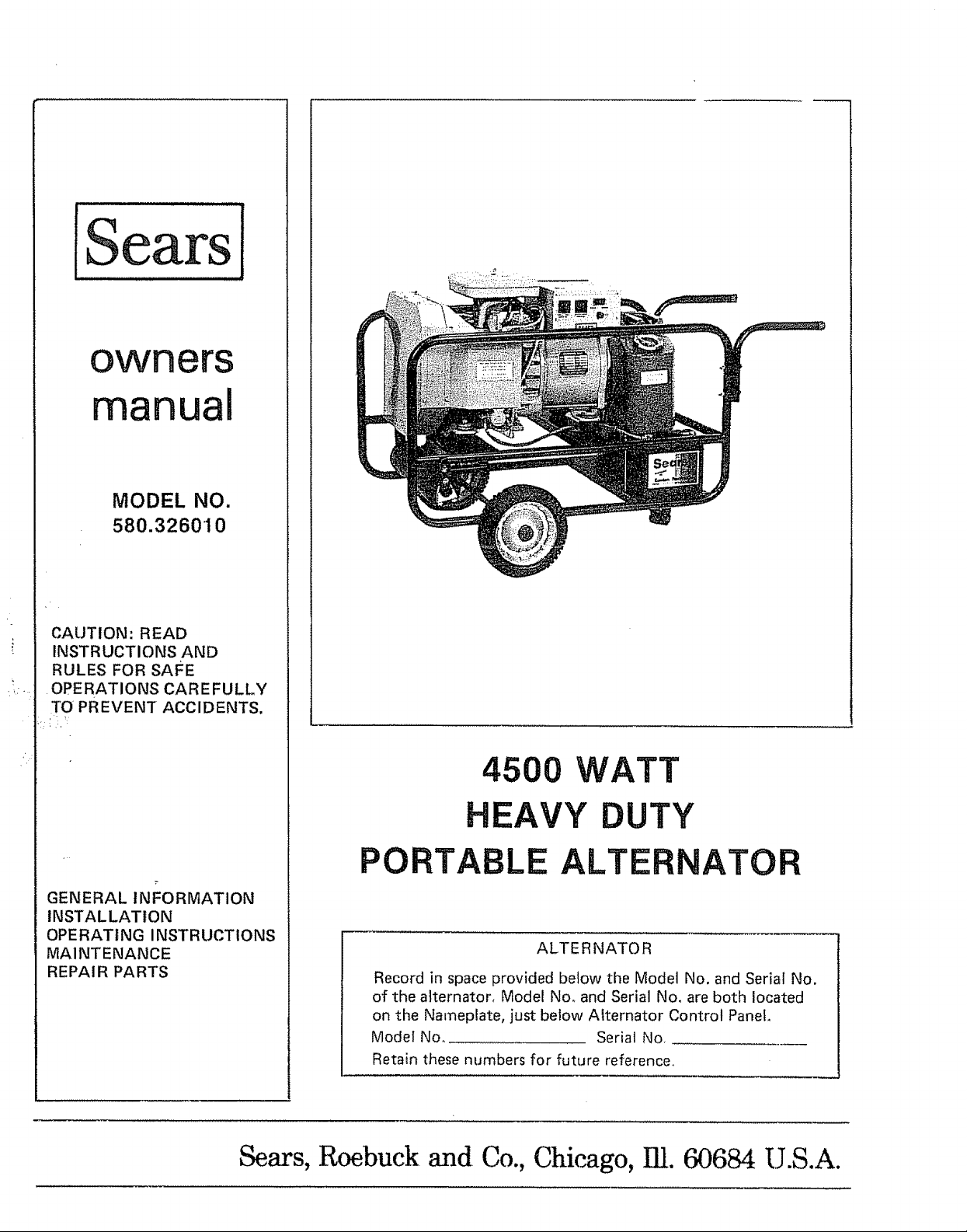
4500 WATT
HEAVY DUTY
PORTABLE ALTERNATOR
ALTERNATOR
Record in space provided below the Model No. and Serial No.
of the alternator, Model No, and Serial No. are both located
on the Nameplate, just below Alternator Control Panel.
Model Noo Serial No,
Retain these numbers for future reference,,
FULL ONE YEAR WARRANTY
For one year from the date of purchase, Sears will repair any defect in
material or workmanship in this alternator at no charge°
If the alternator is used for commercial or rental purposes, this warranty
applies for only thirty days from the date of purchase.
Warranty service is available by contacting the nearest Sears Store or Service
Center throughout the United States.
This warranty gives you specific legal rights, and you may also have other
rights which vary from state to state.
Sears, Roebuck and Co.
Sears Tower
BSC 41-3
Chicago, I L 60684
INTRODUCTION
Your Owner's Manual is meant to provide you with instructions for safe and proper operation of
the 4500 watt portable alternator, Read its contents carefully and comply with all instructions
and rules for' safe operation. With proper care, your alternator will give years of dependable elec-
tric power.
_IL CAUTION
Engines are shipped without oil. Any attempt to start your alternator before the recom =
mended oil has been properly added will result in an engine failure.
RULES FOR SAFE OPERATION
_ Your portable alternator' produces
dangerously high voltages,, Never permit un-
qualified people especially children to
operate the unit.
_Never handle electrical equipment
while standing in water, while barefoot, or
while hands are wet, This carl result in
dangerous electrical shock_
Maintain electrical power' cords in
good condition. Worn, bare or frayed elec-
trical cords are dangerous.
Make sure the wire gauge sizes of
electrical power cords are large enough to
handle the largest anticipated amperage of
electrical equipment. Using wires that are too
small to handle the amperage load is
dangerous.
enclosure or compartment that might
obstruct the free flow of cooling air. Severe
heat damage to the unit will occur.
_ Gasoline is highly flammable and ex-
plosive. Comply with local laws governing the
storage and handling of gasoline,
_1_ Use care when using your' alternator.
Keep clear of moving parts. Never work on the
unit while it is running. Keep equipment clean
and check frequently for loose, missing,
rusted or damaged nuts, bolts, and other
fasteners,.
_ Never try to adjust governed eng]ne
speed. High engine speed is dangerous, The
alternator will produce the required voltage
and frequency only at 3600 rpm.
Never install the alternator in any
Never run the alternator in any enclos-
ed area. Gasoline engines consume oxygen
and give off DEADLY carbon monoxide gas.
TABI.E OF CONTENTS
WARRANTY ....................... inside Front Cover
RULES FOR SAFE OPERATION
inside Front Cover
SPECIFICATIONS ............................... 1
NOMENCLATURE ........................................... 2
WIRING DIAGRAM ............................................... 3
INSTALLATION OF STAND-BY
POWER SYSTEMS ............................... 4
REPAIR PARTS ........................................ 25-28
Section 1 -- Preparation For Use
Alternator Unpacking and Removal
From Shipping Skid .............................. 5
Parts Shipped With Alternator ......................... 5
Wheel Kit Installation ..................................... 7
Lubrication ........................................... 8
Battery Installation ................................ 9
Battery Connections .................................. 9
Fill Fuel Tank ..................................... 10
Install Fuel Tank ................................ 10
Cord Sets for 120 Volt, 15 Amp Outlets ......... 10
Optional Wiring Connections - 240 Volt
Connector Plug .......................... 11
Optional Wiring Connections - 120 Volt,
30 Amp Connector Plug ....................... 11
Grounding The Alternator .......................... 12
Section 2 -- Operating Instructions
Do and Don't Chart ...................................... 13
Before Starting the Engine ................................ 14
Starting the Engine .................................. 15
Stopping the Engine ................................ 16
Wattage and Power .................................... 16
Using the 120 Volt, 15 Amp Outlets ................. 16
Using the 120 Volt, 30 Amp Outlet ............... 16
Using the 240 Volt, 20 Amp Outlet ................. 17
Don't Overload the Alternator ....................... 17
Motor Starting Requirements ........................ 17
Charging a Battery ......................................... 18
Section 3 -- Preventive Maintenance
Maintenance Chart ....................................... 19
General Inspection ................................... 19
Change Oil ............................................. 20
Service Air Cleaner ............................... 21
Inspect 30 Amp Fuse ............................... 21
Spark Plugs ......................................... 22
Clean Fuel Tank ....................................... 22
Inspect Cooling Fins ........................... 22
De-Carbonize Muffler .................................. 23
Replace Fuel Filter .................................. 23
De-Carbonize Engine Cylinder Heads ............ 23
Storage ............................................... 23
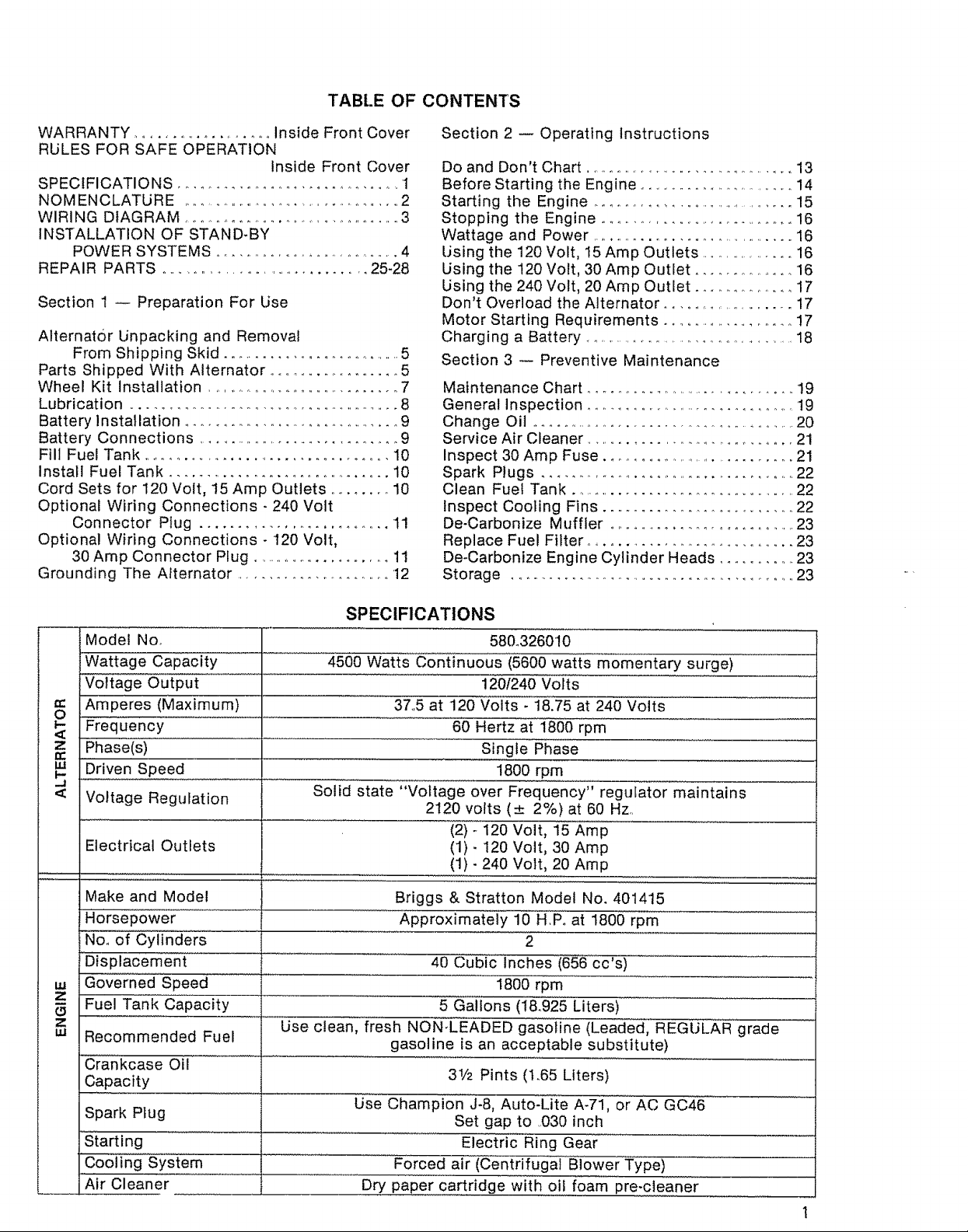
SPECIFICATIONS
Model Noo 58&326010
IWattage Capacity 4500 Watts Continuous (5600 watts m'omentary surgei .............
Voltage Output 120f240 Volts
Amperes (Maximum) ....................................37.,5 at 120 Voi"ts _18175at 240"Volts .......
Frequency ...... i ......................60 Hertz a{ 1800 rpm ...................
==
.....Phase(s) Single Phase
Driven Speed
Voltage Regulation
Electrical Outlets
Make and Model
Horsepower
No. of Cylinders
....Displacemen{ ........
Governed Speed
z
Fuel Tank Capacity
c3
Z
w
Recommended Fuel
Crankcase Oil
Capacity
Solid state "Voltage over Frequency" regulator maintains
2120 volts (_+ 2%) at 60 Hz.
...................... (2io' 120 Volt, 15 Amp
..... ,,, "",::',','L,,,, ......... ,,,
Briggs & Stratton Model No. 401415
Approximatei'y iO HIP. at 1800 rpm
40 Cubic Inches (656 cc's)
5 Gallons (1&925 Liters)
........Use clean, fresh NON:LEADED gasot'ine (Leaded, REGULAR grade
gasoline is an acceptable substitute)
31/2 Pints (I.65 Liters)
1800 rpm
(1) - 120 Volt, 30 Amp
(1) - 240 Volt, 20 Amp
2
1800 rpm
Spark Plug use' Champion J-8, Auto-Lite A-71i"or AC G046 ......
Starting Electric Ring Gear
Cooling System .................... Forced airiCentrifugal' Blower Type) ............................
...... Air Cleaner ......................... ...............Dry paper cartridge w"it'lqoil f0ampre-cieaner '
Set gap to .030 inch
1
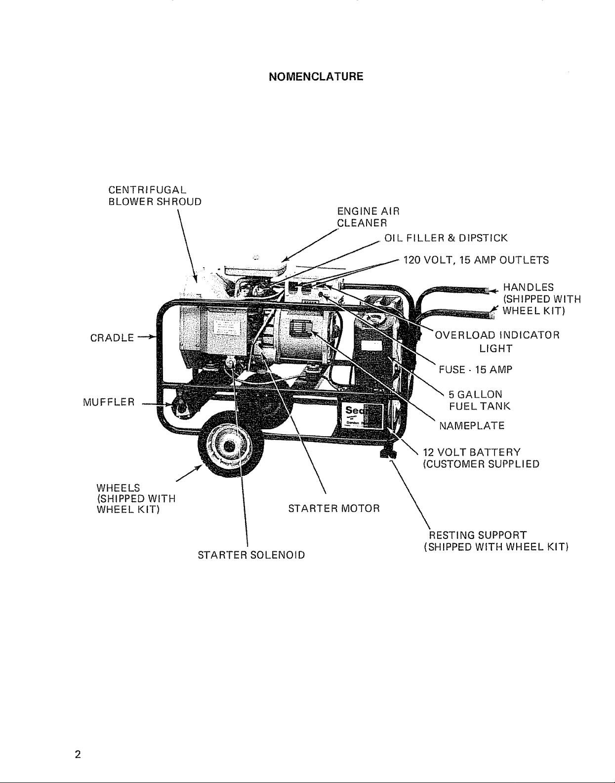
CENTRIFUGAL
BLOWER SHROUD
NOMENCLATURE
ENGINE AIR
CLEANER
OIL FILLER & DIPSTICK
120 VOLT, 15 AMP OUTLETS
HANDLES
(SHIPPED WITH
WHEEL KIT)
CRADLE
MUFFLER
WHEELS
(SHIPPED WITH
WHEEL KIT)
STARTER MOTOR
STARTER SOLENOID
INDICATOR
LIGHT
FUSE - 15 AMP
5 GALLON
FUEL TANK
NAMEPLATE
12 VOLT BATTERY
_IIUSTOME R SUPPLI ED
RESTING SUPPORT
(SHIPPED WITH WHEEL KIT)
2
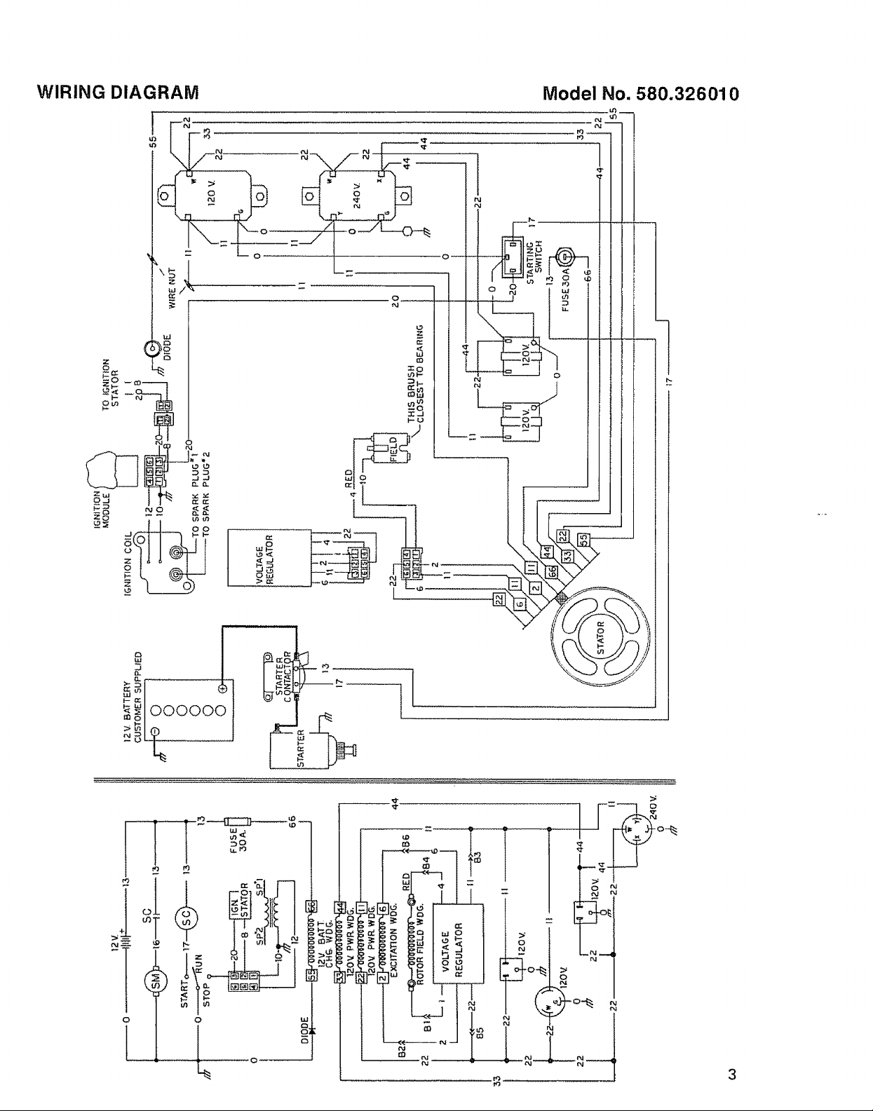
WIRING DIAGRAM
Model No. 580.326010
o !ci
_ oooooo
V)
DO
0 0
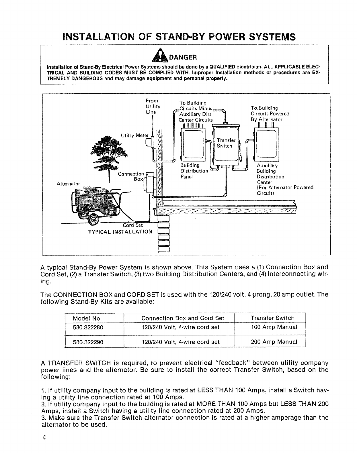
INSTALLATION OF STAND-BY POWER SYSTEMS
_I_DANGER
installation of Stand-By Electrical Power Systems should be done by a QUALIFIED electrtctam ALL APPLICABLE ELEC-
TRICAL AND BUILDING CODES MUST BE COMPLIED WITH. improper installation methods or procedures are EX-
TREMELY DANGEROUS add may damage equipment and personal property°
Alternator
Meter _
Box _
Cord Set
TYPICAL INSTALLATION
F! om
Utility
Line
To Building
Circuits To.Bu liding
Auxiliary Dist Circuits Powered
enter Circuits By Alternator
Building
Distribution I AuxiliaryBuilding
1\
Panel _ DistributionCenter
.... Circuit)
(For-Alternator Powered
A typical Stand-By Power System is shown above° This System uses a (1) Connection Box and
Cord Set, (2) a Transfer Switch, (3) two Building Distribution Centers, and (4) interconnecting wir-
ing.
The CONNECTION BOX and CORD SET is used with the 120/240 volt, 4-prong, 20 amp outlet. The
following Stand-By Kits are available:
Model No. Connection Box and Cord Set Transfer Switch
580.322280 120/240 Volt, 4-wire cord set 100 Amp Manual
580.322290 !201240 Volt, 4-wire cord set 200 Amp Manual
A TRANSFER SWITCH is required, to prevent electrical "feedback" between utility company
power lines and the alternator. Be sure to install the correct Transfer Switch, based on the
following:
1. if utility company input to the building is rated at LESS THAN 100 Amps, install a Switch hav-
ing a utility line connection rated at 100 Amps.
2. If utility company input to the building is rated at MORE THAN 100 Amps but LESS THAN 200
Amps, install a Switch having a utility line connection rated at 200 Amps.
3. Make sure the Transfer Switch alternator connection is rated at a higher amperage than the
alternator to be used.
4
SECTION 1
PREPARATION FOR USE
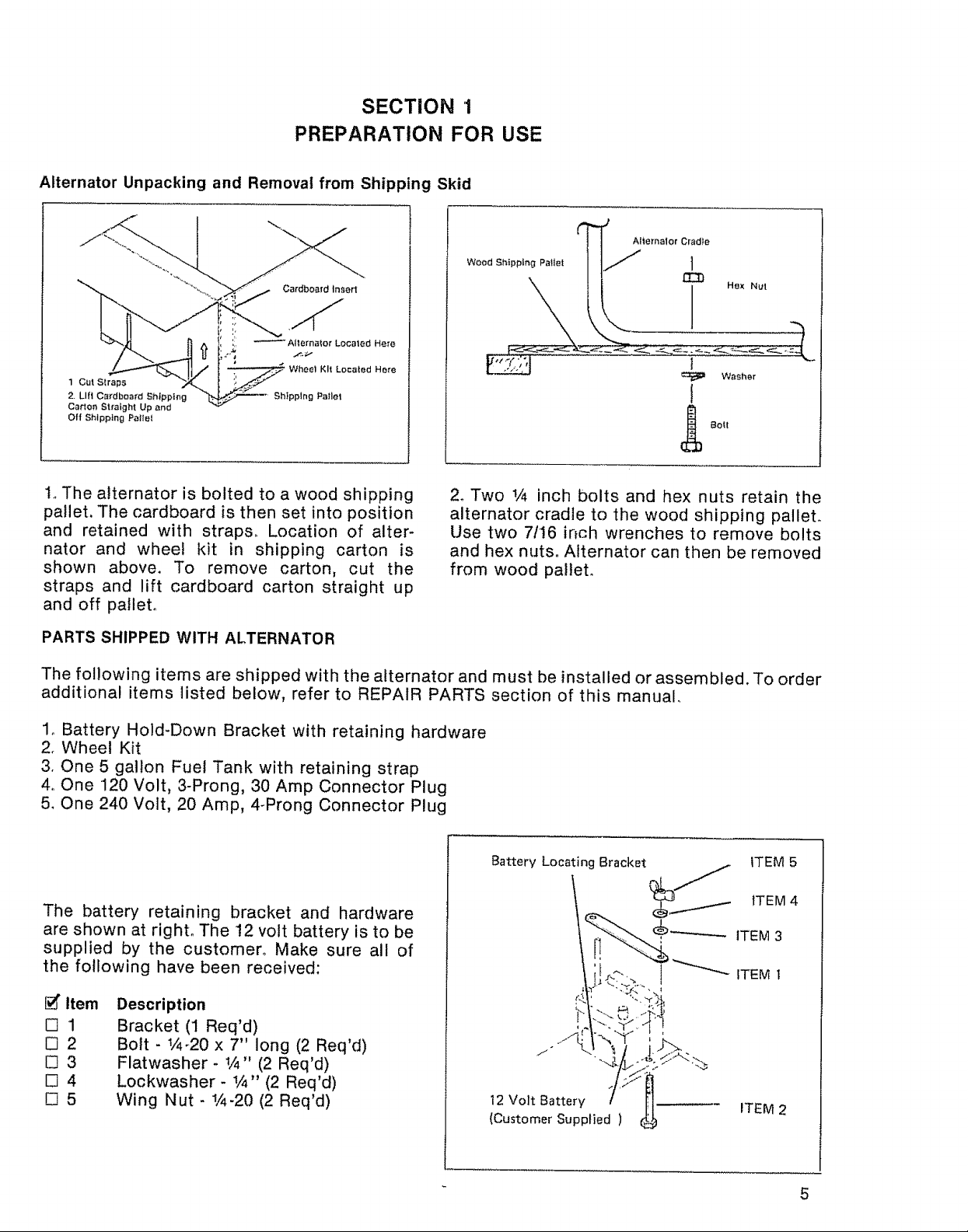
Alternator Unpacking and Removal from Shipping Skid
Cardboard Insert
Alternator Localed Here
1 Cut Straps
2. Lift Cardboard Shtpplng
Carton Straight Up and
Off Shipping Pallet
Kit Located Here
Shipping Pallet
¢ "4
| Alternator Cradle
Wood Sh,pping PatIet " !.j ]
?
Washer
!
_b Bolt
1oThe alternator is bolted to a wood shipping
pallet, The cardboard is then set into position
and retained with straps., Location of alter-
nator and wheel kit in shipping carton is
shown above. To remove carton, cut the
2. Two 1/4 inch bolts and hex nuts retain the
alternator cradle to the wood shipping palleL
Use two 7/16 inch wrenches to remove bolts
and hex nuts° Alternator can then be removed
from wood pallet°
straps and lift cardboard carton straight up
and off pallet°
PARTS SHIPPED WITH ALTERNATOR
The following items are shipped with the alternator and must be installed or assembled. To order
additional items listed below, refer to REPAIR PARTS section of this manual.
1_ Battery Hold-Down Bracket with retaining hardware
2. Wheel Kit
3. One 5 gallon Fuel Tank with retaining strap
4o One 120 Volt, 3-Prong, 30 Amp Connector Plug
5. One 240 Volt, 20 Amp, 4-Prong Connector Plug
Battery Locating Bracket ITEM 5
__ ITEM 4
The battery retaining bracket and hardware
are shown at right° The 12 volt battery is to be
@_.--.f
ITEM 3
supplied by the customer° Make sure all of
the following have been received:
_ ITEM I
[_ Item
D1
N2
_3
E34
D5
Description
Bracket (1 Req'd)
Bolt - V4-20 x 7" long (2 Req'd)
Flatwasher- %" (2 Req'd)
Lockwasher - 1/4" (2 Req'd)
Wing Nut - _/4-20 (2 Req'd)
t2 Volt Battery ITEM 2
(Customer Supplied )
5
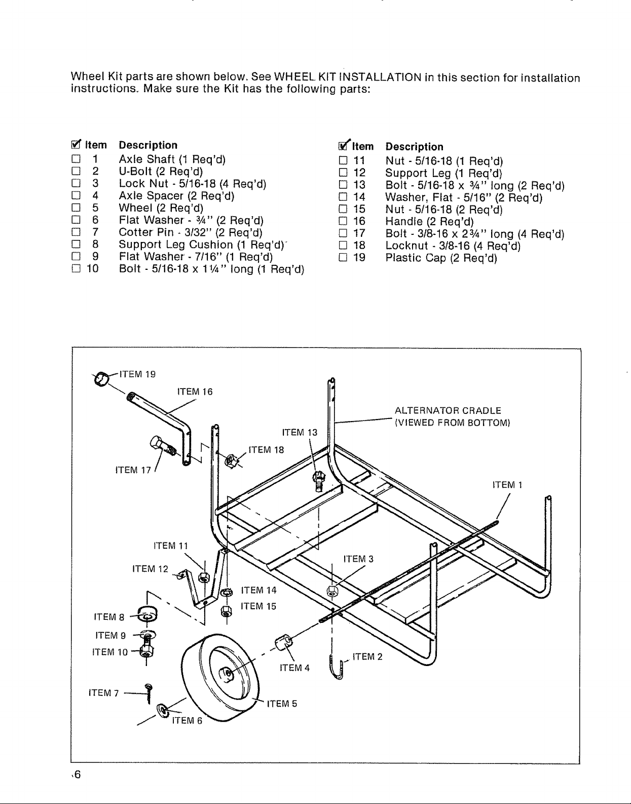
Wheel Kit parts areshownbelow,SeeWHEELKITINSTALLATIONinthis section for installation
instructions. Make sure the Kit hasthe following parts:
_" Item
[] 1
[] 2
[] 3
[] 4
[] 5
[] 6
[] 7
[] 8
[] 9
[]10
Description [_ltem
Axle Shaft (1 Req'd) [] 11
U-Bolt (2 Req'd) [] 12
Lock Nut - 5/16-18(4Req'd) [] 13
Axle Spacer (2Req'd) [] 14
Wheel (2 Req'd) C] 15
Flat Washer- a/4"(2 Req'd) [] 16
Cotter Pin - 3/32" (2 Req'd) [] 17
Support Leg Cushion (1 Req'd)" [] 18
Flat Washer'- 7116" (1 Req'd) [] 19
Bolt - 5/16-18 x 11/4" long (1 Req'd)
19
ITEM 16
ITEM 13
ITEM 18
Description
Nut - 5/16-18 (1 Req'd)
Support Leg (1 Req'd)
Bolt - 5/16-18 x 3/4" tong (2 Req'd)
Washer, Flat - 5/16" (2 Req'd)
Nut - 5116-t8 (2 Req'd)
Handle (2 Req'd)
Bolt - 318-16 x 2s,4" long (4 Req'd)
Locknut -3/8-16 (4 Req'd)
Plastic Cap (2 Req'd)
ALTERNATOR CRADLE
(VIEWED FROM BOTTOM)
ITEM 17
ITEM 12
ITEM 8 __._!
T-
ITEM 11
" ITEM 15
ITEM t
/
ITEM 3
ITEM 14
1
1
ITEM 2
ITEM 4
ITEM 5
,6
Strap Bracket
Fuel Tanl<
/
,i, Rubber Strap
120 Volt, 30 Amp,
4-Prong Connector Plug
240 Volt, 20 Amp, 4-Prong
Connector Plug
!
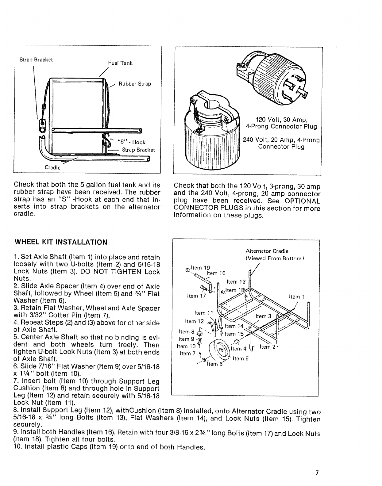
Check that both the 5 gallon fuel tank and its
rubber strap have been received. The rubber
strap has an "S" -Hook at each end that in-
serts into strap brackets on the alternator
cradle°
Check that both the 120 Volt, 3-prong, 30 amp
and the 240 Volt, 4-prong, 20 amp connector
plug have been received. See OPTIONAL
CONNECTOR PLUGS in this section for more
information on these plugs.
WHEEL KIT INSTALLATION
Alternator Cradle
1. Set Axle Shaft (Item 1) into place and retain
loosely with two U-bolts (Item 2) and 5/16-18
Lock Nuts (item 3). DO NOT TIGHTEN Lock
Nuts.
2. Slide Axle Spacer (Item 4) over end of Axle
._Item 19 /
_'-_em 16
"_'3 f Item t 3
(Viewed From Bottom)
Shaft, followed by Wheel (item 5) and 3/4" Fiat
Washer (Item 6).
3_ Retain Flat Washer, Wheel and Axle Spacer
with 3/32" Cotter Pin (Item 7).
4. Repeat Steps (2) and (3) above for other side
of Axle Shaft.
te 11 __ Item3
Item 12 ._j_ it_--em__
5. Center Axle Shaft so that no binding is evi-
dent and both wheels turn freely. Then
tighten U-bolt Lock Nuts (Item 3) at both ends
of Axle Shaft.
Item 10 'I" ( !t _Xitem 4 [,.1" item 2
Item 7 _m_j item 5
6o Slide 7116" Fiat Washer (Item 9) over 5116-18
x ! 1/4" bolt (Item t0)o
7_ Insert bolt (Item 10) through Support Leg
Cushion (Item 8) and through hole in Support
Leg (Item 12) and retain securely with 5116-i8
Lock Nut (Item 11).
8o Install Support Leg (Item 12), withCushion (Item 8) installed, onto Alternator Cradle using two
5/16-18 x 3/4" long Bolts (Item 13), Flat Washers (Item 14), and Lock Nuts (Item 15). Tighten
securely.
9. install both Handles (Item 16)o Retain with four 3/8-16 x 23/4'' long Bolts (Item 17) and Lock Nuts
(Item 18). Tighten all four bolts.
10. Install plastic Caps (Item 19) onto end of both Handles.
7
LUBRICATION
CAUTION
Engines are shipped without oil. Any attempt to start the engine before the recommended
oil has been properly added may result in an engine failure.
Service the engine crankcase with a high quality detergent oil having a classification which in-
cludes"For Service MS, SC, SD or SE", and as recommended in the following CHART. Oil recom-
mendations are the result of extensive testing° use no special additives with the recommended
oilo
Recommended Oil
l t !,
oFT20 o 29 49 _ ................8o mo
°C- 30 - 20..............!0 ........... 0 10 20 30 40
"TEMPERATURE RANGE ANTICIPATED BEFORE NEXT OIL CHANGE
*if not available, a synthetic oil may be used having- 5W-30 or 5W-40 viscosity.
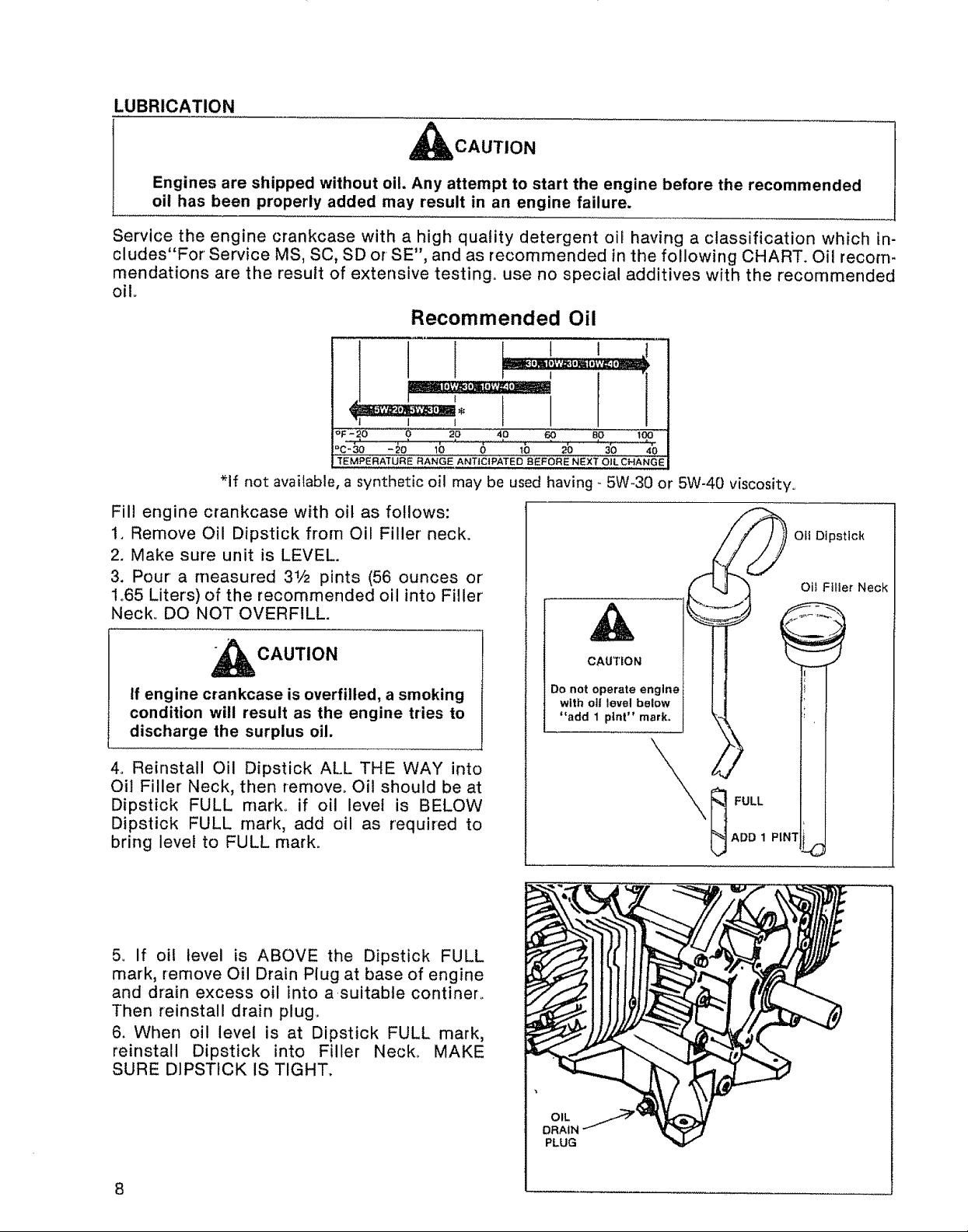
Fill engine crankcase with oil as follows:
1. Remove Oil Dipstick from Oil Filler neck.
2. Make sure unit is LEVEL.
3. Pour a measured 31/2 pints (56 ounces or'
1o65 Liters) of the recommended oil into Filler'
Neck_ DO NOT OVERFILL.
CAUTION
If engine crankcase is overfilled, a smoking
condition will result as the engine tries to
discharge the surplus oil.
4. Reinstall Oil Dipstick ALL THE WAY into
Oil Filler Neck, then remove° Oil should be at
Dipstick FULL mark° if oil level is BELOW
Dipstick FULL mark, add oil as required to
bring level to FULL mark°
t
A
CAUTION
Do not operate engine
with oll level below
"add 1 pint" mark.
FULL
ADD 1 PINTt_
Oii FIHer Neck
Oft Dipstick
5o if oil level is ABOVE the Dipstick FULL
mark, remove Oil Drain Plug at base of engine
and drain excess oil into asuitable continer_
Then reinstall drain plug.
6. When oil level is at Dipstick FULL mark,
reinstall Dipstick into Filler Neck° MAKE
SURE DIPSTICK IS TIGHT.
8
OIL _'
DRAIN
PLUG
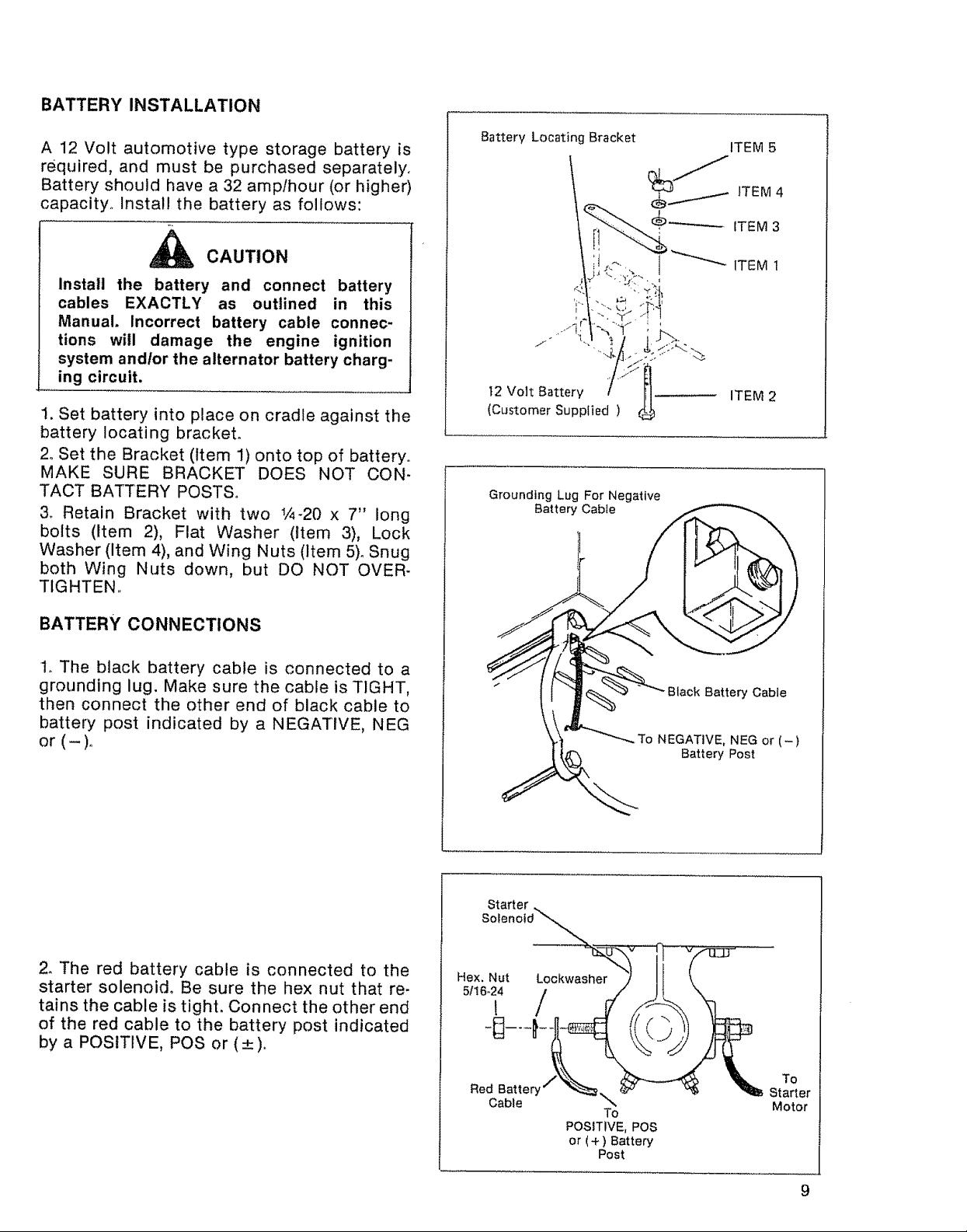
BATTERY INSTALLATION
A 12 Volt automotive type storage battery is
required, and must be purchased separately.
Battery should have a 32 amplhour (or higher)
capacity° Install the battery as follows:
_ CAUTION
install the battery and connect battery
cables EXACTLY as outlined in this
Manual. Incorrect battery cable connec-
tions will damage the engine ignition
system andlor the alternator battery charg-
ing circuit,
1. Set battery into place on cradle against the
battery locating bracket.
2. Set the Bracket (Item 1) onto top of battery.
MAKE SURE BRACKET DOES NOT CON*
TACT BATTERY POSTS.
3o Retain Bracket with two t/4-20 x 7" long
bolts (Item 2), Flat Washer (Item 3), Lock
Washer (item 4), and Wing Nuts (Item 5). Snug
both Wing Nuts down, but DO NOT OVER-
TIGHTEN..
Battery Locating Bracket
t2 Volt Battery fl
(Customer Supplied )
Grounding Lug For Negative
Battery Cable
ITEM 5
h
ITEM 2
BATTERY CONNECTIONS
1o The black battery cable is connected to a
grounding lug. Make sure the cable is TIGHT,
then connect the other end of black cable to
battery post indicated by a NEGATIVE, NEG
or (-)o
2. The red battery cable is connected to the
starter solenoid° Be sure the hex nut that re-
tains the cable is tight. Connect the other end
of the red cable to the battery post indicated
by a POSITIVE, POS or (4-).
Red BatteQ
Cable
..To NEGATIVE, NEG or (-)
To
POSITIVE, POS
or (+ ) Battery
Post
Black Battery Cable
Battery Post
To
Starter
Motor
9
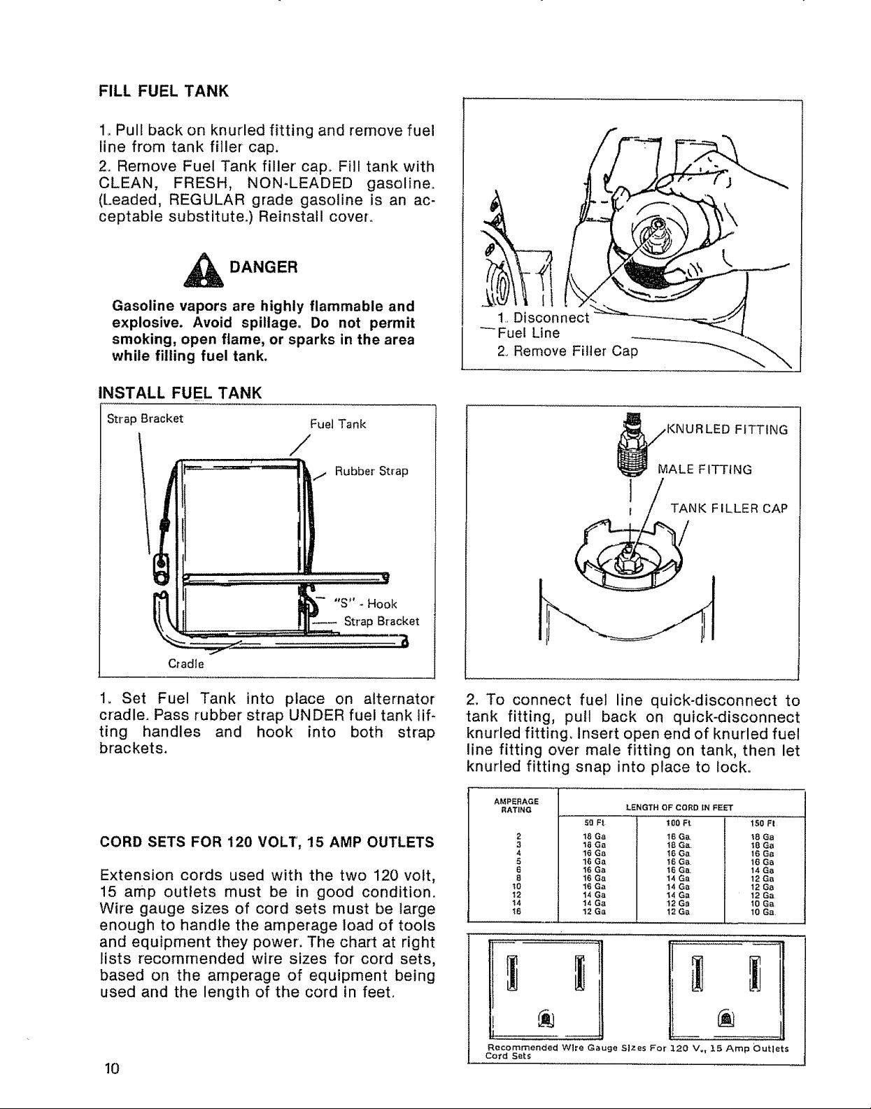
FILL FUEL TANK
1_ Pull back on knurled fitting and remove fuel
line from tank filler cap.
2. Remove Fuel Tank filler cap° Fill tank with
CLEAN, FRESH, NON-LEADED gasoline.
(Leaded, REGULAR grade gasoline is an ac-
ceptable substitute.) Reinstall cover.
_ DANGER
Gasoline vapors are highly flammable and
explosive. Avoid spillage. Do not permit
smoking, open flame, or sparks in the area
while filling fuel tank.
INSTALL FUEL TANK
2. Remove Filler Cap
Strap Bracket
Fuel Tank
/
/ Rubber Strap
"S" - Hook
Strap Bracket
Cradle
1. Set Fuel Tank into place on alternator
cradle. Pass rubber strap UNDER fuel tank lif-
ting handles and hook into both strap
brackets.
CORD SETS FOR 120 VOLT, 15 AMP OUTLETS
Extension cords used with the two 120 volt,
15 amp outlets must be in good condition.
Wire gauge sizes of cord sets must be large
enough to handle the amperage load of tools
and equipment they power. The chart at right
lists recommended wire sizes for cord sets,
based on the amperage of equipment being
used and the length of the cord in feet.
1 T_NK FILLER CAP
2. To connect fuel line quick-disconnect to
tank fitting, pull back on quick-disconnect
knurled fitting. Insert open end of knurled fuel
line fitting over male fitting on tank, then let
knurled fitting snap into place to locko
AMPERAGE
RATING
2
3
4
5
6
8
!0
t2
14
t6
18 Ga
18 Ga
16 Ga
16 Ga
16 Ga
16 Ga
16 Ga
14 Ga
14 Ga
12 Ga
LENGTH OF CORD IN FEET
50 Ft j
100 Ft 150 F!
18 Ga, t8 Ga
18 Ga, t8 Ga
16 Ga 16 Ga
16 Ga 16 Ga
16 Ga. 14 Ga
14 Ga 12 Ga
14 Ga 12 Ga
14 Ga 12 Ga
12 Ga 10 Ga
12 Ga 10 Ga
10
Outlets
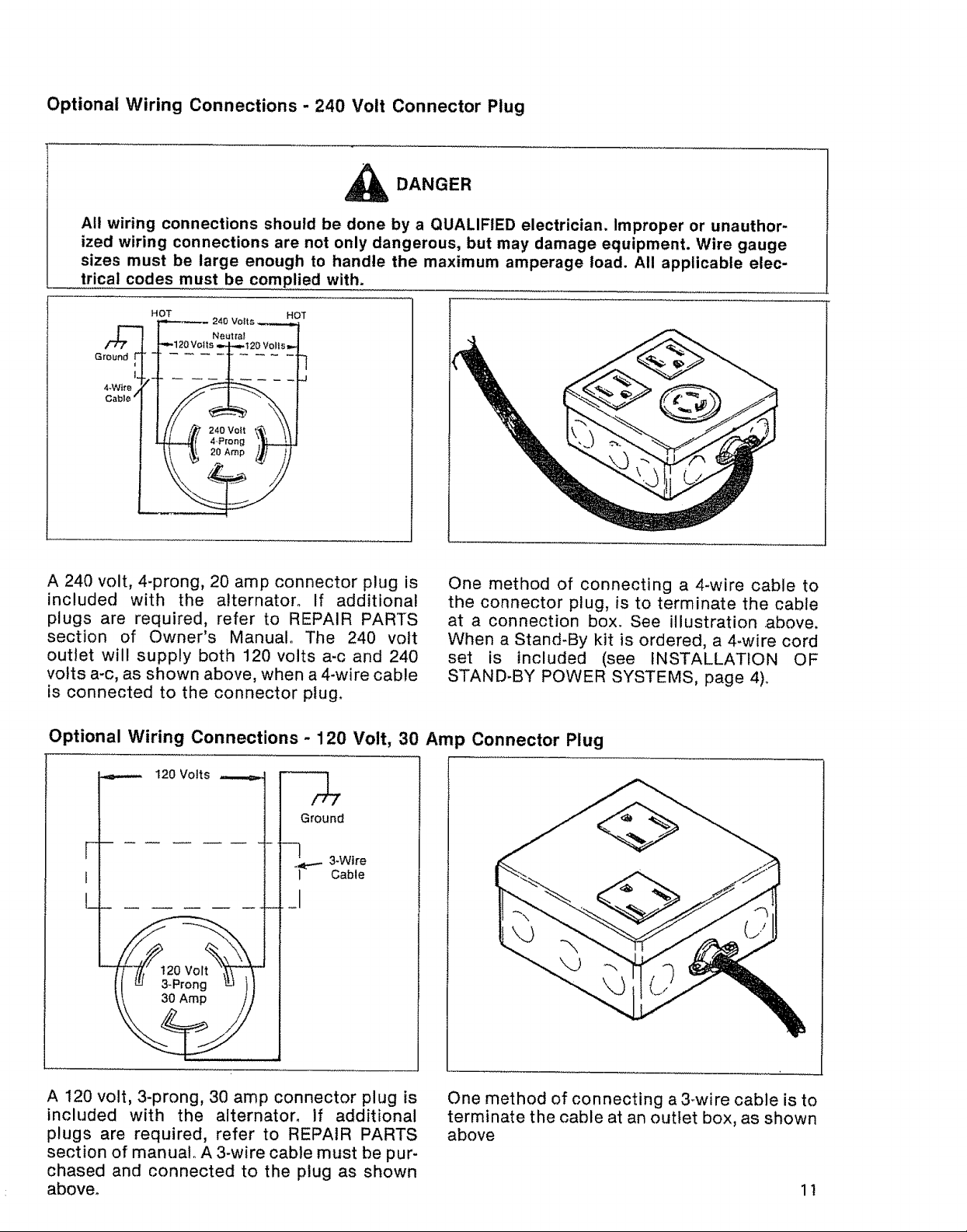
Optional Wiring Connections - 240 Volt Connector Plug
_1_ DANGER
All wiring connections should be done by a QUALIFIED electrician. Improper or unauthor-
ized wiring connections are not only dangerous, but may damage equipment. Wire gauge
sizes must be large enough to handle the maximum amperage load. All applicable elec-
trical codes must be complied with.
HOT HOT
Ground
A 240 volt, 4-prong, 20 amp connector plug is
included with the alternatoro If additional
plugs are required, refer to REPAIR PARTS
section of Owner's Manual. The 240 volt
outlet will supply both 120 volts a-c and 240
volts a-c, as shown above, when a 4-wire cable
is connected to the connector plug.
Optional Wiring Connections - 120 Volt, 30 Amp Connector Plug
240 Volts
One method of connecting a 4-wire cable to
the connector plug, is to terminate the cable
at a connection box. See illustration above.
When a Stand-By kit is ordered, a 4-wire cord
set is included (see INSTALLATION OF
STAND-BY POWER SYSTEMS, page 4)_
,==,.,...- I20 Volts ,,,....,.,,_,
F" 3-Wlre
! Cable
/#i"
Ground
-2--
L __1
A 120 volt, 3-prong, 30 amp connector plug is
included with the alternatoro if additional
plugs are required, refer to REPAIR PARTS
section of manual° A 3-wire cable must be pur-
chased and connected to the plug as shown
above.
One method of connecting a 3-wire cable is to
terminate the cable at an outlet box, as shown
above
11
 Loading...