

Craftsman 57211629 Owner’s Manual
Owner's Manual
ERRFTSMRN,
CONTOUR SANDER
Model No. 572.11629
Caution:
Before using this product,
read this manual and follow
all its Safety Rules and
Operating Instructions.
Sears, Roebuck and Co., Hoffman Estates, IL 60179
Safety
Operation
Maintenance
Parts
Espa5ol
Table of Contents Page
Warranty ..................................................... 2
Power Tool Safety Rules ...................................... 3-4
Symbols ..................................................... 5
Functional Description and Specifications .......................... 6
Operating Instructions ........................................ 7-8
Accessory Tips ................................................ 8
Tool Tips ................................................... 8-9
Maintenance ............................................... 9-10
Service Parts .............................................. 11-12
Sears Warranty
Full One Year Warranty on Craftsman Contour Sander
If this Craftsman Contour Sander fails to give complete satisfaction within one
year from the date of purchase, Sears will replace it free of charge.
If this Contour Sander is used for commercial or rental purposes, this warranty
applies for only one year from the date of purchase.
Warranty Service
Warranty service is available by returning this Craftsman Contour Sander to
your nearest Sears Store in the United States.
This warranty applies only while this Contour Sander is used in the United
States.
This warranty gives you specific legal rights, and you may also have other
rights which vary from state to state.
Sears, Roebuck and Co., Dept. 817WA, Hoffman Estates, IL 60179
2

Read and understand all instructions. Failure to follow all instructions
listed below, may result in electric shock, fire and/or serious personal injury.
SAVE THESE INSTRUCTIONS
Work Area
Keep your work area clean and well lit.
Cluttered benches and dark areas invite
accidents.
Do not operate power tools in explosive
atmospheres, such as in the presence of
flammable liquids, gases, or dust. Power
tools create sparks which may ignite the
dust or fumes.
Keep by-standers, children, and visitors
away while operating a power tool.
Distractions can cause you to lose control.
Electrical Safety
Double Insulated tools are equipped with
a polarized plug (one blade is wider than
the other.) This plug will fit in a polarized
outlet only one way. If the plug does not
fit fully in the outlet, reverse the plug. If it
still does not fit, contact a qualified
electrician to install a polarized outlet. Do
not change the plug in any way. Double
Insulation [] eliminates the need for the
three wire grounded power cord and
grounded power supply system. Before
plugging in the tool, be certain the outlet
voltage supplied is within the voltage
marked on the nameplate. Do not use "AC
only" rated tools with a DC power supply.
Avoid body contact with grounded
surfaces such as pipes, radiators, ranges
and refrigerators. There is an increased
risk of electric shock if your body is
grounded. If operating the power tool in
damp locations is unavoidable, a Ground
Fault Circuit Interrupter must be used to
supply the power to your tool. Electrician's
rubber gloves and footwear will further
enhance your persona] safety.
Don't expose power tools to rain or wet
conditions. Water entering a power tool
will increase the risk of electric shock.
Do not abuse the cord. Never use the
cord to carry the tools or pull the plug
from an outlet. Keep cord away from
heat, oil, sharp edges or moving parts.
Replace damaged cords immediately.
Damaged cords increase the risk of electric
shock.
When operating a power tool outside,
use an outdoor extension cord marked
"W-A" or "W." These cords are rated for
outaoor use and reduce the risk of electric
shock. Refer to "Recommended sizes of
Extension Cords" in the Accessory section
of this manual.
Personal Safety
Stay alert, watch what you are doing and
use common sense when operating a
power tool. Do not use tool while tired or
under the influence of drugs, alcohol, or
medication. A moment of inattention while
operating power tools may result in serious
personal injury.
Dress properly. Do not wear loose
clothing or jewelry. Contain long hair.
Keep your hair, clothing, and gloves
away from moving parts. Loose clothes,
jewelry, or long hair can be caught in
moving parts. Keep handles dry, clean and
free from oil and grease.
Avoid accidental starting. Be sure switch
is "OFF" before plugging in. Carrying
tools with your finger on the switch or
plugging in tools that have the switch "ON"
invites accidents.
Remove adjusting keys or wrenches
before turning the tool "ON". A wrench or
a key that is left attached to a rotating part
of the tool may result in personal injury.
Do not overreach. Keep proper footing
and balance at all times. Proper footing
and balance enables better control of the
tool in unexpected situations.
Use safety equipment. Always wear eye
protection. Dust mask, non-skid safety
shoes, hard hat, or hearing protection must
be used for appropriate conditions.
Tool Use and Care
Use clamps or other practical way to
secure and support the workpiece to a
stable platform. Holding the work by hand
or against your body is unstable and may
1end to toss of control.
Do not force tool. Use the correct tool for
your application. The correct tool will do
the job better and safer at the rate for which
it is designed.
Do not use tool if switch does not turn it
"ON" or "OFF". Any tool that cannot be

controlled with the switch is dangerous and
must be repaired.
Disconnect the plug from the power
source before making any adjustments,
changing accessories, or storing the
tool. Such preventive safety measures
reduce the risk of starting the tool
accidentally. Store idle tools out of reach
of children and other untrained persons,
Tools are dangerous in the hands of
untrained users.
Maintain tools with care. Keep cutting
tools sharp and clean. Properly
maintained tools, with sharp cutting edges
are less likely to bind and are easier to
control. Any alteration or modification is a
misuse and may result in a dangerous
condition.
Check for misalignment or binding of
moving parts, breakage of parts, and any
other condition that may affect the tools
operation. If damaged, have the tool
serviced before using. Many accidents are
caused by poorly maintained tools. Develop
a periodic maintenance schedule for your
tool.
Use only accessories that are
recommended by the manufacturer for
your model. Accessories that may be
suitable for one tool, may become
hazardous when used on another toot.
Service
Tool service must be performed only by
qualified repair personnel. Service or
maintenance performed by unqualified
personnel could result in a risk of injury. F_
example: internal wires may be misplaced
or pinched, safety guard return springs ma
be improperly mounted.
When servicing a tool, use only identical
replacement parts. Follow instructions il
the Maintenance section of this manual.
Use of unauthorized parts or failure to
follow Maintenance Instructions may creab
a risk of electric shock or injury. Certain
cleaning agents such as gasoline, carbon
tetrachloride, ammonia, etc. may damage
plastic parts.
Unplug the sander before changing
accessories. Accidental start-ups may
occur if sander is plugged in while changing
an accessory.
Always wear eye protection and a dust
mask for dusty applications and when
sanding overhead. Sanding particles can
be absorbed by your eyes and inhaled
easily and may cause health complications.
Use special precautions when sanding
chemically pressure treated lumber,
paint that may be lead based, or any
other materials that may contain
carcinogens. A suitable breathing
respirator and protective clothing must be
worn by all persons entering the work area.
Work area should be sealed by plastic
sheeting and persons not protected should
be kept out until work area is thoroughly
cleaned.
Do not wet sand with this sander. Liquid:
entering the motor housing are an electric_
shock hazard.
Clamp or secure workpiece when
sanding. Clamping the workpiece prevent
it from being ejected from under the sancle
and leaves both hands free to control the
tool,
Keep the cord away from the accessory
The cord can become entangled with the
pad or contour.
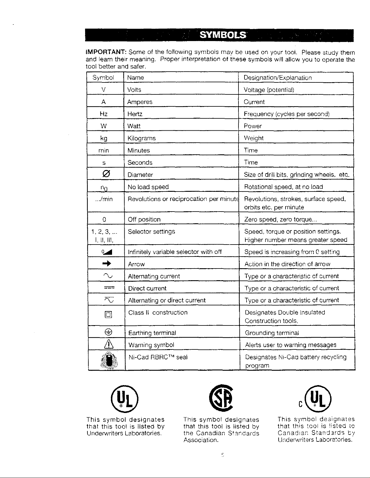
IMPORTANT:Someof thefollowingsymbolsmaybeusedon yourtooi. Pleasestudythem
andlearntheirmeaning.Properinterpretationof thesesymbolswillallowyouto operatethe
tool betterandsafer.
Symbol Name
V Volts
A Amperes
Hz Hertz
W Watt
kg Kilograms
min Minutes
S
O
no
..Jmin
0
1,2,3 ....
I, II, III,
Seconds
Diameter
No load speed
Revolutions or reciprocation per minute
Off position
Selector settings
Designation/Explanation
Voltage (potential)
Current
Frequency (cycles per second)
Power
Weight
Time
Time
Size of drill bits, grinding wheels, etc.
Rotational speed, at no load
Revolutions, strokes, surface speed,
orbits etc. per minute
Zero speed, zero torque...
Speed, torque or position settings.
Higher number means greater speed
Infinitely variable selector with off
Arrow
Alternating current
Direct current
Alternating or direct current
[]
@
Class II construction
Earthing terminal
Warning symbol
Ni-Cad RBRC TM seal
®
This symbol designates
that this tool is listed by
Underwriters Laboratories.
Speed is increasing from 0 setting
Action in the direction of arrow
Type or a characteristic of current
Type or a characteristic of current
Type or a characteristic of current
Designates Double Insulated
Construction tools.
Grounding terminal
Alerts user to warning messages
Designates Ni-Cad battery recycling
program
This symbol designates
that this tool is listed by
the Canadian Standards
Association,
This symbol designates
that this tool is !isted [c
Canadian Standards b'!
UndenNriters Laboratories.
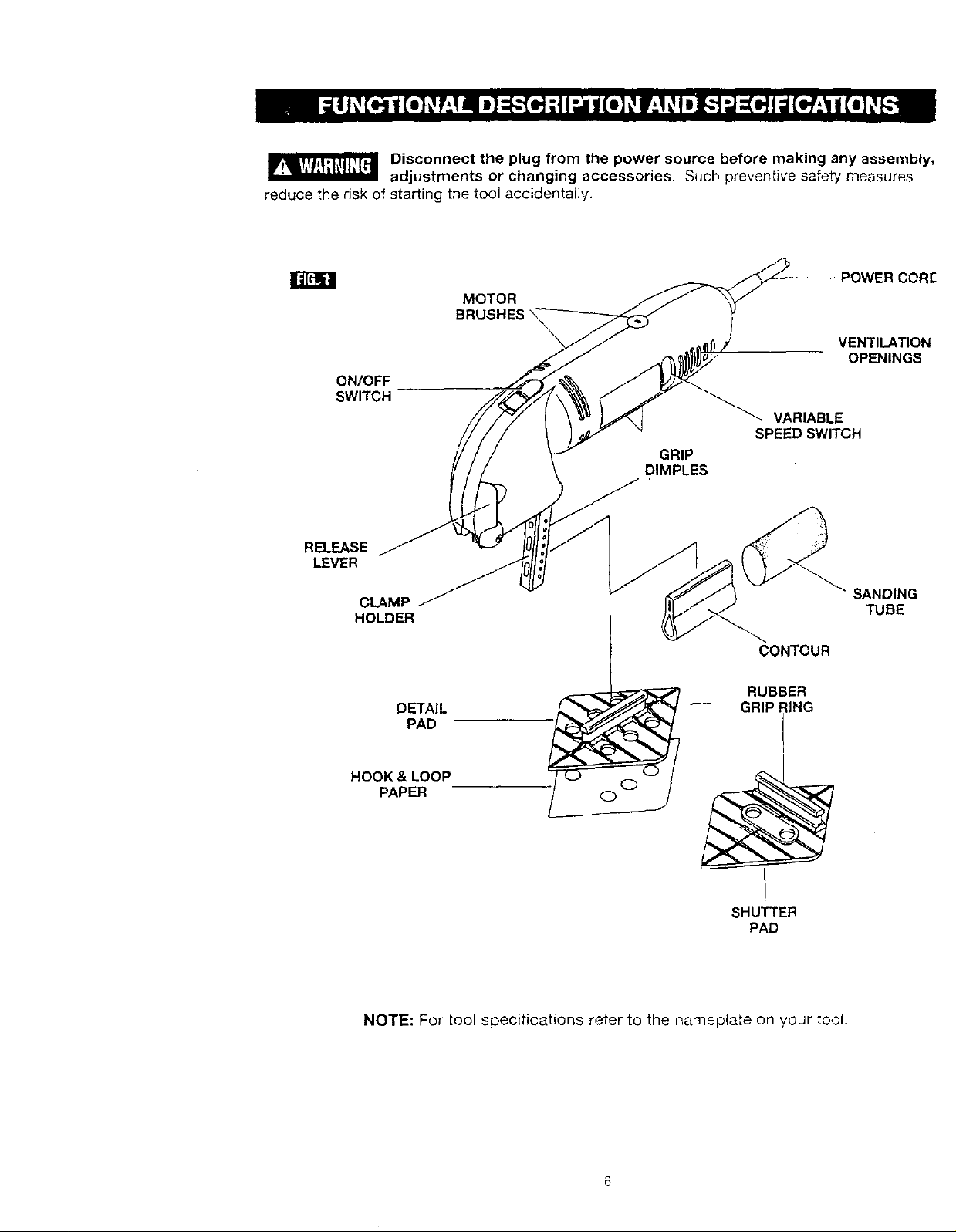
Disconnect the plug from the power source before making any assembly,
adjustments or changing accessories. Such preventive safety measures
reduce the risk of starting the tool accidentally.
I;AtM!
SWITCH
RELEASE
LEVER
ON/OFF
CLAMP
HOLDER
DETAIL
PAD
MOTOR
BRUSHES
--POWER CORE
\
VARIABLE
SPEED SWITCH
GRIP
DIMPLES
CONTOUR
RUBBER
GRIP lING
I
VENTILATION
OPENINGS
SANDING
TUBE
HOOK & LOOP
PAPER
y
SHUTTER
PAD
NOTE: For tool specifications refer to the nameplate on your tool.
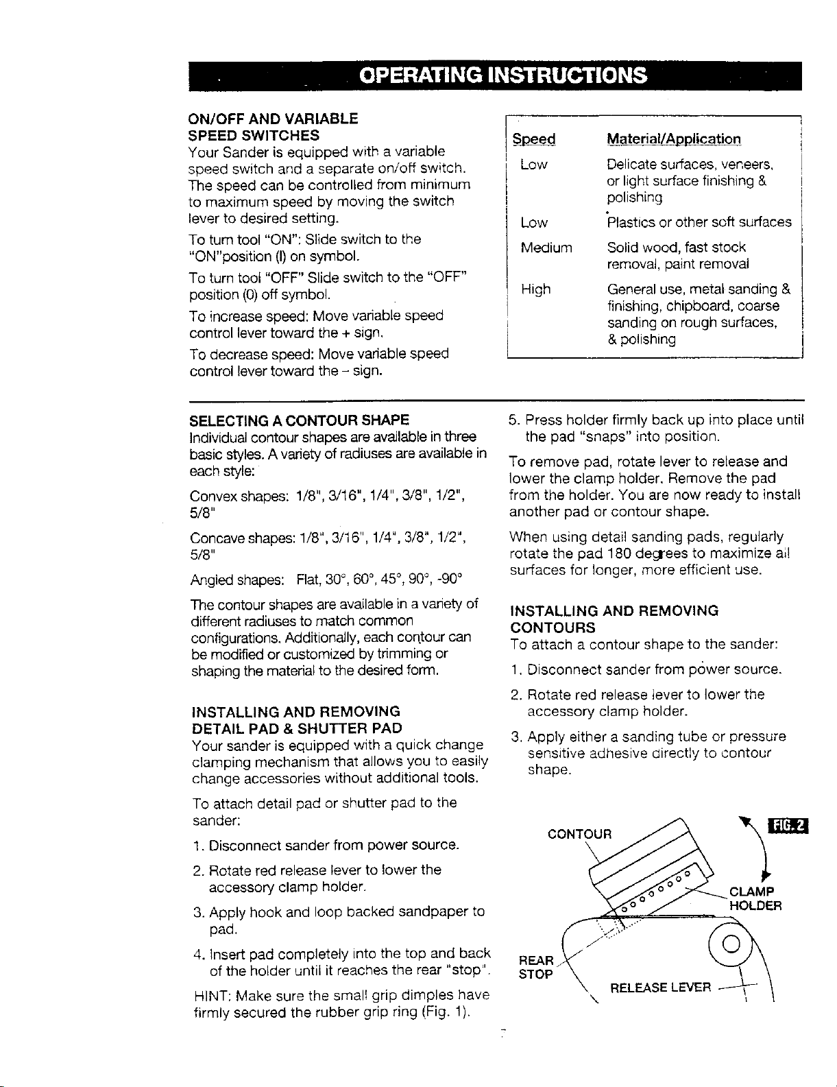
ON/OFF AND VARIABLE
SPEED SWITCHES
Your Sander is equipped with a variable
speed switch and a separate on/off switch.
The speed can be controlled from minimum
to maximum speed by moving the switch
lever to desired setting.
To turn tool "ON": Slide switch to the
"ON'position (I)on symbol.
To turn tool "OFF" Slide switch to the "OFF"
position (0) off symbol.
To increase speed: Move variable speed
control lever toward the + sign.
To decrease speed: Move variable speed
control Fevertoward the - sign.
Speed
Low
Low
Medium
High
Material/Application
Delicate surfaces, veneers,
or light surface finishing &
polishing
"Plasticsor other soft surfaces
Solid wood, fast stock
removal, paint removal
General use, metal sanding &
finishing, chipboard, coarse
sanding on rough surfaces,
& polishing
SELECTING A CONTOUR SHAPE
Individual contour shapes are available in three
basic styles. A variety of radiuses are available in
each style:
Convex shapes: 1/8", 3/16", 1/4", 3/8", 1/2",
5/8"
Concave shapes: 1/8", 3/16", 1/4", 3/8", 1/2",
5/8"
Angled shapes: Flat, 30°, 60°, 45 °, g0°, -90 °
The contour shapes are available in a variety of
different radiuses to match common
configurations. Additionally, each contour can
be modified or customized by trimming or
shaping the material to the desired form.
INSTALLING AND REMOVING
DETAIL PAD & SHUTTER PAD
Your sander is equipped with a quick change
clamping mechanism that allows you to easily
change accessories without additional tools.
To attach detail pad or shutter pad to the
sander:
1. Disconnect sander from power source.
2. Rotate red release lever to lower the
accessory clamp holder.
3. Apply hook and loop backed sandpaper to
pad.
5. Press holder firmly back up into place until
the pad "snaps" into position.
To remove pad, rotate lever to release and
lower the clamp holder. Remove the pad
from the holder. You are now ready to install
another pad or contour shape.
When using detail sanding pads, regularly
rotate the pad 180 degrees to maximize ai!
surfaces for longer, more efficient use.
INSTALLING AND REMOVING
CONTOURS
To attach a contour shape to the sander:
1. Disconnect sander from power source.
2. Rotate red release lever to lower the
accessory clamp holder.
3. Apply either a sanding tube or pressure
sensitive adhesive directly to contour
shape.
CONTOUR
CLAMP
HOLDER
4. Insert pad completely into the top and back
of the holder until it reaches the rear "stop".
HINT: Make sure the small grip dimples have
firmly secured the rubber grip ring (Fig. 1).
REAR
STOP
RELEASE LEVER
\
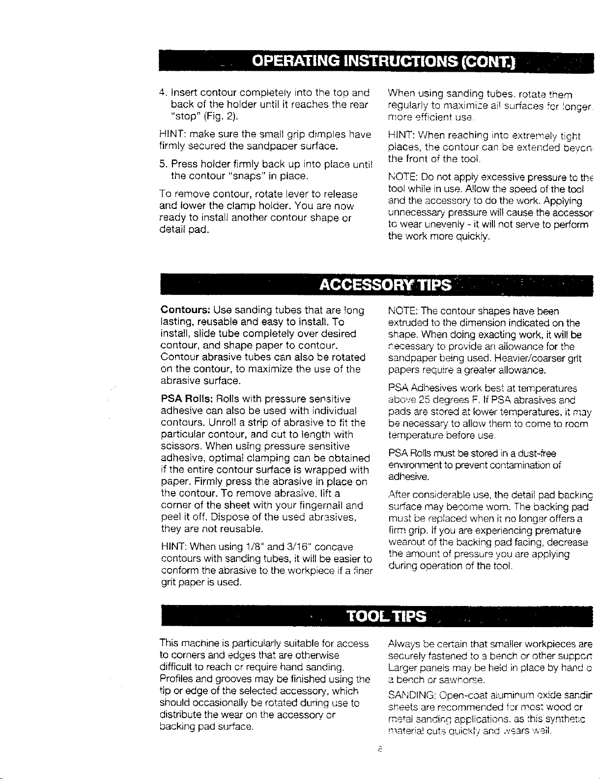
4. Insert contour completely into the top and
back of the holder until it reaches the rear
"stop" (Fig. 2).
When using sanding tubes, rotate them
regularly to maximize all surfaces for longer
more efficient use.
HINT: make sure the small grip dimples have
firmly secured the sandpatuer surface.
5. Press holder firmly back up into place until
the contour "snaps" in place,
To remove contour, rotate lever to release
and lower the clamp holder. You are now
ready to install another contour shape or
detail pad.
Contours: Use sanding tubes that are !ong
lasting, reusable and easy to install. To
install, slide tube completely over desired
contour, and shape paper to contour.
Contour abrasive tubes can also be rotated
on the contour, to maximize the use of the
abrasive surface.
PSA Rolls: Rolls with pressure sensitive
adhesive can also be used with individual
contours. Unroll a strip of abrasive to fit the
particular contour, and cut to length with
scissors, When using pressure sensitive
adhesive, optimal clamping can be obtained
if the entire contour surface is wrapped with
paper. Firmly press the abrasive in place on
the contour. To remove abrasive, lift a
corner of the sheet with your fingernail and
peel it off. Dispose of the used abrasives,
they are not reusable.
HINT: When using 1/8" and 3/16" concave
contours with sanding tubes, it will be easier to
conform the abrasive to the workpiece if a finer
grit paper is used.
HINT: When reaching into extremely tight
places, the contour can be extended beycn
the front of the tool.
NOTE: Do not apply excessive pressure to th_
tool while in use. A!low the speed of the tool
and the accessory to do the work. Applying
unnecessary pressure wil! cause the accessor
to wear unevenly - it will not serve to perform
the work more quickly.
NOTE: The contour shapes have been
extruded to the dimension indicated on the
shape. When doing exacting work, it will be
necessary' to provide an allowance for the
sandpaper being used. Heavier/coarser grit
papers require a greater allowance.
PSA Adhesives work best at temperatures
above 25 degrees F. If PS& abrasives and
pads are stored at lower temperatures, it may
be necessary to allow them to come to room
temperature before use.
PSA Rolls must be stored in a dust-free
envwonment to prevent contamination of
adhesive.
After considerable use. the detail pad backing
sudace may become worn. The backing pad
must be replaced when it no longer offers a
firm grip. If you are experiencing premature
wearout of the backing pad facing, decrease
the amount of pressure you are applying
during operation of the tool.
This machine is particularly suitable for access
to corners and edges that are otherwise
difficult to reach cr require hand sanding.
Profiles and grooves may be finished using the
tip or edge of the selected accessory, which
should occasionally be rotated during use to
distribute the wear on the accessory or
backing pad surface.
Always be ceRain that smaller workpieces are
securely fastened to a bench or other suppcr:
Larger panels may be held in place by hand o
a bench or sawhorse.
SANDING: Open-coat aluminum oxide sandir
sheets are recommended for mos: wood cr
metal sanding applications, as this synthetlc
materia! cuts quic'.d'! and _vears well.
 Loading...