

Craftsman 536.8884 User Manual
CRR FTSMRW
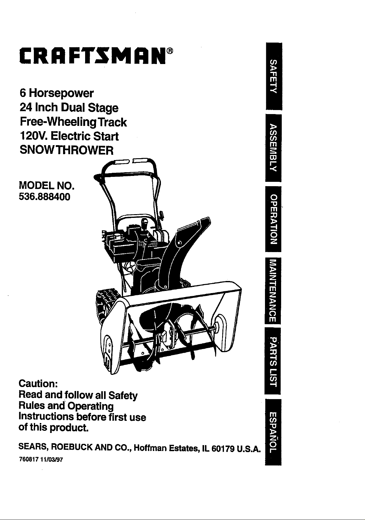
6 Horsepower
24 Inch Dual Stage
Free-WheelingTrack
120V.Electric Start
SNOWTHROWER
MODEL NO.
536.888400
i
Caution:
Read and follow all Safety
Rules and Operating
Instructions before first use
of this product.
SEARS, ROEBUCK AND CO., Hoffman Estates, IL 60179 U.S.A.
760817 11103/97
Table of Contents 2 Service and Adjustments 17-23
Warranty 2 Storage 23-24
Safety Rules 2-4 Troubleshooting 24
Contents of Shipping Carton 4-5 Repair Parts 25-34
Assembly 5-8 Engine Repair Parts 35-40
Operation 8-14 Spanish(Espai_ol) 41-65
Maintenance 15-17 Parts Ordering/Service Back Cover
LIMITED TWO-YEAR WARRANTY ON CRAFTSMAN SNOW THROWER
For two years from the date of purchase, when this Craftsman Snow Thrower is main-
tained, lubricated, and tuned up according to the operating and maintenance instructions in
the owner's manual, Craftsman wilt repair, free of charge, any defect in material or work-
manship.
If this Craftsman Snow Thrower is used for commercial or rental purposes, this warranty
applies for only 90 days from the date of purchase.
This warranty does not cover the following:
• Items which become worn during normal use, such as spark plugs, drive belts and
shear pins.
• Repairs necessary because of operator abuse or negligence, including bent crank
shafts and the failure to maintain the equipment according to the instructions con-
tained in the owner's manual.
WARRANTY SERVICE IS AVAILABLE BY RETURNING THE CRAFTSMAN SNOW
THROWER TO THE NEAREST CRAFTSMAN SERVICE CENTEWDEPARTMENT IN
THE UNITED STATES. THIS WARRANTY APPLIES ONLY WHILE THIS PRODUCT IS
IN USE IN THE UNITED STATES.
This warranty gives you specific legal fights, and you may also have other rights which
may vary from state to state.
Sears, Roebuck and Co., D817WA, Hoffman Estates, IL 60179
/_ Look for this symbol to point out iroportant safety precautions. It means--
Z_ CAUTION: Always spark
plug wire and place wire where it cannot
contact spark plug to prevent accidental
starting when setting-up, transporting,
adjusting or making repairs.
IMPORTANT: Safety standards require
operator presence controls to minimize the
risk of injury. Your snow thrower is
equipped with such controls. Do not attempt
to defeat the function of the operator
)resence control under any circumstances.
i
ATTENTIONI!! Become alertll! Your safety is Involved.
disconnect
California Proposition 65
WARNING:The
engine exhaust from this
product contains chemicals known
to the State of California to cause
cancer, birth defects or other
TRAINING
1. Read the operator's manual carefully.
Be thoroughly familiar with the controls
and the proper use of the snow thrower.
Know how to stop the snow thrower and
disengage the controls quickly.
2. Never allow children to operate the
snow thrower and keep them away
while it is operating. Never allow adults
to operate the snow thrower without
proper instruction. Do not car_ passen-
gers.
3. Keep the area of operation clear of all
persons, padicularly small children and
pets.
4. Exercise caution to avoid slipping or
falling, especially when operating in
reverse.
reproductiveharm.
PREPARATION .
1. Thoroughly inspect the area where the
snow thrower is to be used and
remove all doormats, sleds, boards,
wires and other foreign objects. 5.
2. Disengage all clutches before starting
the engine (motor).
3. Do not operate the snow thrower
without wearing adequate winter outer
.garments. Wear footwear that will
=mprove footing on slippery surfaces. 6.
4. Handle fuel with care; it is highly
flammable.
(a) Use an approved fuel container.
(b) Never remove fuel tank cap or add
fuelto a running engine or hot 7.
engine.
(c) Fill fuel tank outdoors with
extreme care. Never fill fuel tank
indoors .....
(d) Replace fuel tank cap securely 8.
and wipe up spilled fuel.
(e) Never store fuel or snow thrower
with fuel in the tank inside of a
building where fumes may reach
an open flame or spark.
(f) Check fuel supply before each 9..
use, allowing space for expansion
as the heat of the engine (motor)
and/or sun can cause fuel to
expand. 10.
5. Use extension cords and receptacles
as specified by the manufacturer for all
snow throwers with electric drive
motors or electric starting motors.
6. Adjust the snow thrower height to clear
gravel or crushed rock surfaces.
7. Never attempt to make any adjust- 11.
ments while the engine (motor)
is running (except when specifically
recommended by the manufacturer).
8. Let engine (motor) and snow thrower 12.
adjust to outdoor temperatures before
starting to clear snow.
9. Always wear safety glasses or eye 13.
shields during operation or while
performing an adjustment or repair to
protect eyes from foreign objects that
may be thrown from the snow thrower.
OPERATION ._ _ 14.
1. Do not operate this machine if you are
taking drugs or other medication which
can cause drowsiness or affect your 15.
ability to operate this machine.
2. Do not use this machine if you are
mentally or physically unable to
operate this machine safely. 16.
3. Do not put hands or feet near or under
rotating parts. Keep clear of the
discharge opening at all times.
Exercise extreme caution when operat-
ing on or crossing gravel drives, walks,
or roads. Stay alert for hidden hazards
or traffic.
After striking a foreign object, stop the
engine (motor), remove the wire from
the spark plug, disconnect the cord on
electric motors, thoroughly inspect the
snow thrower for any damage, and
repair the damage before restarting and
operating the snow thrower.
If the snow thrower should start to
vibrate abnormally, stop the (motor) and
check immediately for the cause. •
Vibration is generally a warning of
trouble.
Stop the engine (motor) whenever you
leave the operating position, before
unclogging the auger/impeller housin9
or discharge guide, and when making
any repairs, adjustments, or inspections.
When cleaning, repairing, or inspecting,
make certain the auger/impeller and a I '=
moving parts have stopped. Disconnect
the spark plug wire and keep the wire
away from the plug to prevent acciden-
tal starting.
Take all possible precautions when
leaving the snow thrower unattended.
Disengage the auger/impeller, stop
engine, and remove key.
Do not run the engine indoors, except
when starting the engine and for
transporting the snow thrower in or out
of the building. Open the outside doors;
exhaust fumes are dangerous (contain-
ing CARBON MONOXIDE, an ODOR-
LESS and DEADLY GAS).
Do not clear snow across the face of
slopes. Exercise caution when changing
direction on slopes. Do not attempt to
clear steep slopes.
Never operate the snow thrower without
proper guards, plates or other safety
protective devices in place_
Never operate the snow thrower near
glass enclosures, automobiles, window
wells, drep-offs, and the like without
proper adjustment of the snow
discharge angle. Keep children and pets
away.
Do not overload the machine capacity
by attempting to clear snow at too fast a
rate.
Never operate the snow thrower at high
transport speeds on slippery surfaces,
Lookbehind and use care when
backing. . :' •
Never direct discharge at bystanders or
allow anyone in front of the snow
thrower.
17. Disengage power to the auged
impeller when snow thrower is
transported or not in use.
18. Use only attachments and accesso-
ries approved by the manufacturer
of the snow thrower (such as tire
chains, electric start kits, etc).
19. Never operate the snow thrower
without good visibility or light.
Always be sure of your footing, and
keep a firm hold on the handles.
Walk; never run.
MAINTENANCE AND STORAGE
1. Check shear bolts and other bolts
frequently for proper tightness to be
sure the snow thrower =sin safe
working condition.
2. Never store the snow thrower with
fuel in the fuel tank inside a
building where ignition sources are
present such as hot water and
space heaters, clothes dryers, and
the like. Allow the engine to cool
before storing in any enclosure.
3. Always refer to operator's manual
instructions for important details if
the snow thrower is to be stored for
an extended period.
4. Maintain or replace safety and instruc-
tion labels, as necessary.
5. Run the snow thrower a few minutes
after throwing snow to prevent freeze-
up of the auger/impeller.
A
/_ WARNING: This snow thrower is for
use on sidewalks, driveways and other
ground level surfaces. _.
Caution should be exemi_ed while using on
steep sloping surfaces. DO NOT USE
SNOW THROWER ON SURFACES
ABOVE GROUND LEVEL such as roofs of
residences, garages, porches or other such
structures or buildings.
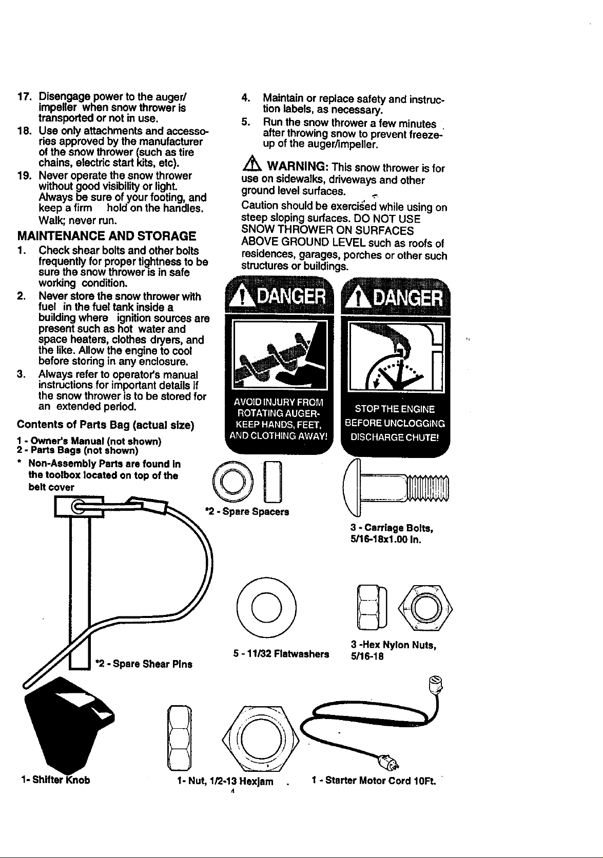
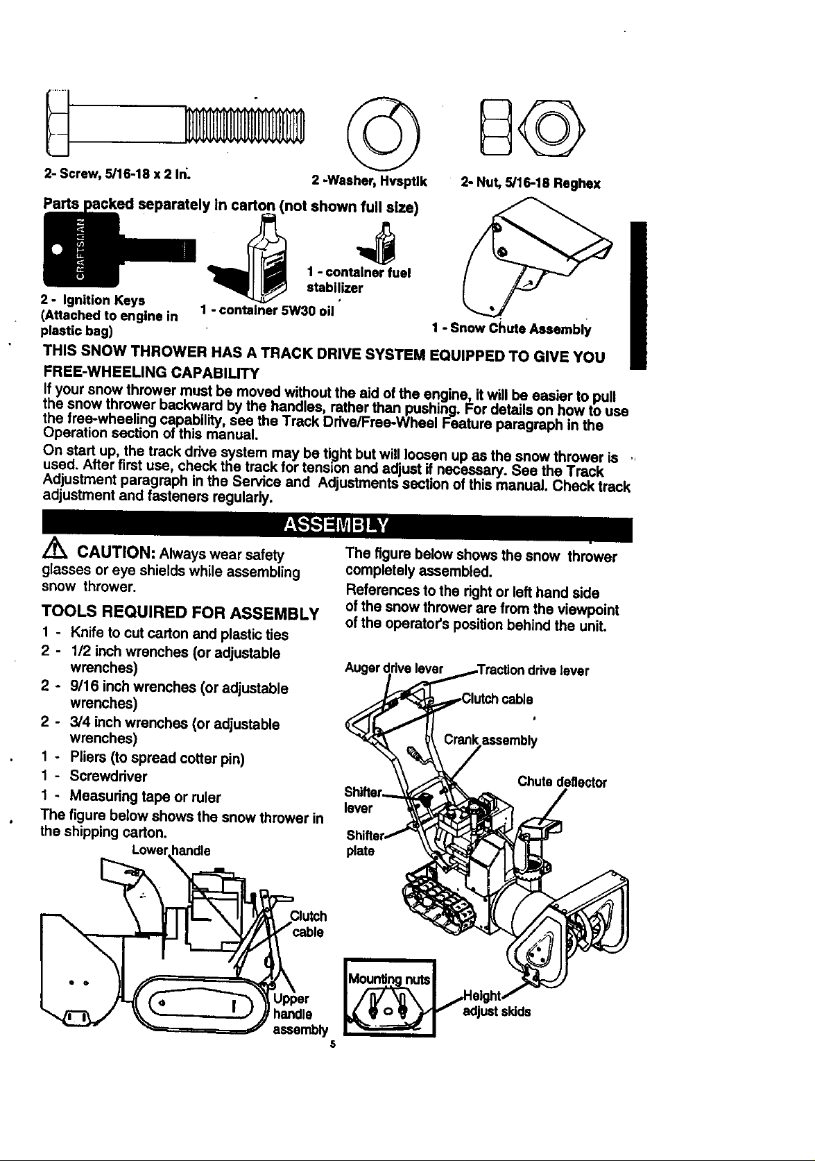
Contents of Parts Bag (actual size)
1 - Owner's Manual (not shown)
2 - Parts Bags (not shown)
* Non-Assembly Parts ere found In
the toolbox located on top of the
bett cover
*2 - Spare Shear Pine
*2 - Spare Spacers
5 - 11/32 Flatwashers
3 - Carriage Bolts,
5/16-18xl.00 In.
3 -Hex Nylon Nuts,
5/16-18
1- Shifter Knob 1 - Starter Motor Cord 10Ft.
1- Nut, 1/2-13 Hexlam
L
©
B©
2-Screw,5/16-18 x 2 In'.
Pads
2 - Ignition Keys
{Attached to engine in
plastic bag)
THIS SNOW THROWER HAS A TRACK DRIVE SYSTEM EQUIPPED TO GIVE YOU
FREE-WHEELING CAPABILITY
If your snow thrower must be moved without the aid of the engine, it will be easier to pull
the snow thrower backward by the handles rather than pushing. For details on how to use
the free-wheeling capability, see the Track Drive/Frae-Wheel Feature paragraph in the
Operation section of this manual.
On start up, the track drive system may be ti_ghtbut wilt loosen up as the snow thrower is
used. After first use, check the track for tension and adjust if necessary. See the Track
Adjustment paragraph in the Service and Adjustments section of this manual. Check track
adjustment and fasteners regularly.
Z_ CAUTION: Always wear safety
glasses or eye shields while assembling
snow thrower.
TOOLS REQUIRED FOR ASSEMBLY
1 - Knife tocutcarton and plasticties
2 - 1/2 inchwrenches (or adjustable
wrenches)
2 - 9116 inchwrenches (or adjustable
wrenches)
2 - 3/4 inchwrenches (or adjustable
wrenches)
1 - Pliers (to spread cotterpin)
1- Screwdriver
1 - Measuring tape or ruler
The figure below shows the snow thrower in
the shipping carton.
,in carton (not shown full size)
1 - container 5W30 oil
2 -Washer, Hvsptlk
The figure below shows the snow thrower
completely assembled.
References to the right or left hand side
of the snow thrower are from the viewpoint
of the operator's position behind the unit.
Auger(
lever
plate
2- Nut, 5/16-18 Reghex
1 - Snow Chute Assembly
drivelever
Chutedeflector
Clutch
handle
essemb_j
adjustskids
5
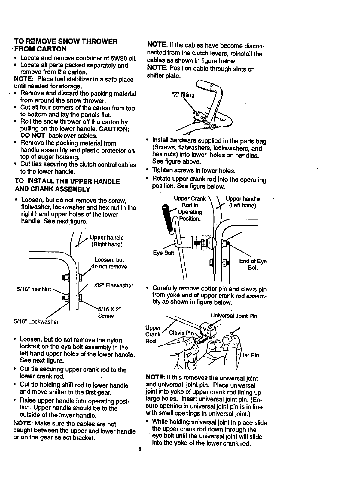
TO REMOVE SNOW THROWER
' FROM CARTON
• Locate and remove container of 5W30 oil.
• Locate all parts packed separately and
remove from the carton.
NOTE: Place fuel stabilizer in a safe place
until needed for storage.
• * Remove and discard the packing matedal
from around the snow thrower.
• Cut all four comers of the carton from top
to bottom and lay the panels flat.
• Roll the snow thrower off the carton by
pulling on the lower handle. CAUTION:
DO NOT backover cables.
• Remove the packing material from
handle assemblyand plastic protector on
top of auger housing.
• Cut ties secudng the clutch control cables
to the lower handle.
TO INSTALLTHE UPPER HANDLE
AND CRANK ASSEMBLY
• Loosen, but do not remove the screw,
flatwasher, Iockwasher and hex nut in the
dght hand upper holes of the lower
handle. See next figure.
NOTE: Ifthe cables have become discon-
nected from the clutch levers, reinstall the
cables as shown in figure below.
NOTE: Position cable through slots on
shifter plate.
• Install hardware supplied in the parts bag
(Screws, flatwashers, Iockwashers, and
hex nuts) into lower holes on handles.
See figure above.
• Tighten screws in lower holes.
• Rotate upper crank rod into the operating
position. See figure below.
Upper Crank Upper handle
Rod In (Left hand)
• Upper handle
(Righthand)
Loosen,but
do not remove
16X2"
Screw
5/16" Look'washer
• Loosen, but do not remove the nylon
lock,nut on the eye bolt assembly in the
left hand upper holes of the lower handle.
See next figure.
• Cut tie secudng upper crank rod to the
lower crank rod.
• Cut tie holding shift rod to lower handle
and move shifter to the first gear.
• Raise upper handle into operating posi-
tion. Upper handle should be to the
outside of the lower handle.
NOTE: Make sure the cables are not
caught between the upper and lower handle
or on the gear select bracket.
Eye Bolt
End of Eye
Bolt
• Carefully remove cotter pin and clevis pin
from yoke end of upper crank rod assem-
bly as shown in figure below.
I
UniversalJoint Pin
Upper
Crank
Rod
NOTE: If this removes the universal joint
and universal joint pin. Place universal
joint into yoke of upper crank rod lining up
large holes. Insert universal joint pin. (En-
sure opening in universal joint pin is in line
with small openings in universal joint.)
• While holding universal joint in place slide
the upper crank rod down through the
eye bolt until the universal joint will slide
into the yoke of the lower crank rod_
6
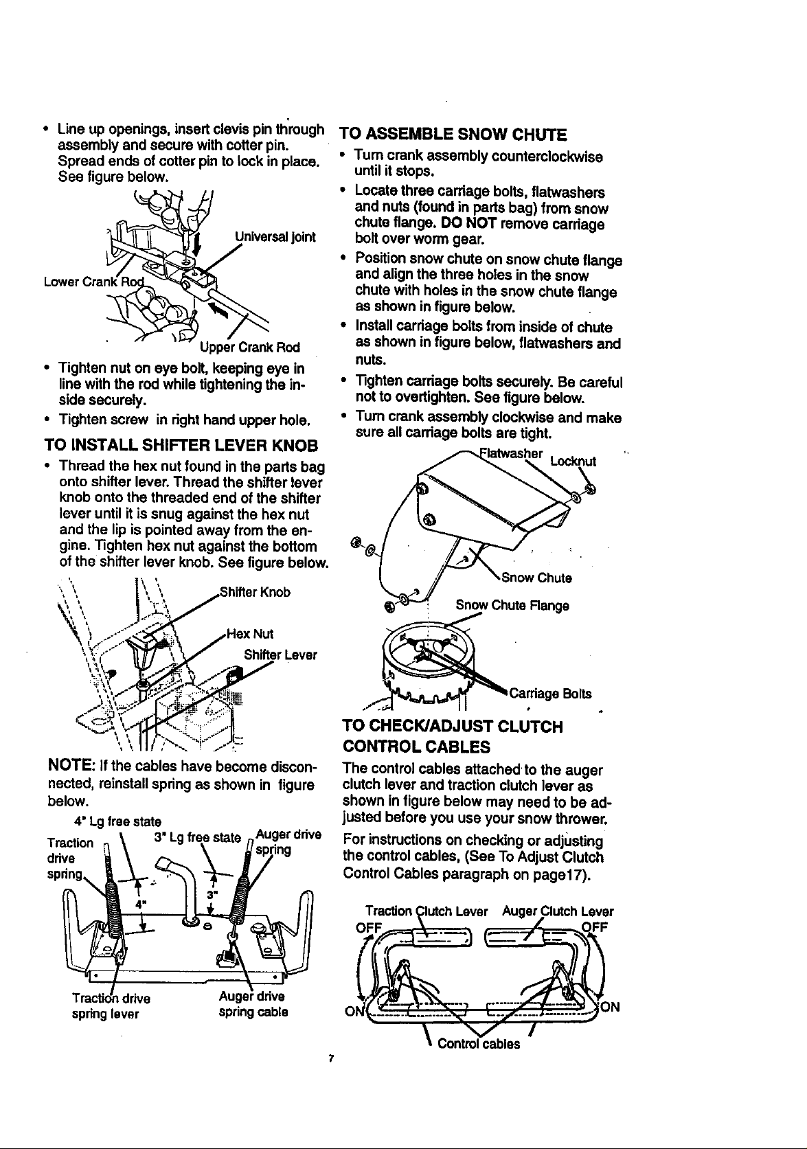
• Lineupopenings,insertclevispinthrough
assemblyandsecurewithcotterpin.
Spreadendsofcotterpinto lockinplace.
Seefigurebelow.
__/ Universaljoint
Upper Crank Rod
• Tighten nut on eye bolt, keeping eye in
line with the rod while tightening the in-
side securely.
• Tighten screw in right hand upper hole.
TO INSTALL SHIFTER LEVER KNOB
• Thread the hex nut found in the parts bag
onto shifter lever. Thread the shifter lever
knob onto the threaded end of the shifter
lever until it is snug against the hex nut
and the lip is pointed away from the en-
gine. "Rghten hex nut against the bottom
of the shifter lever knob. See figure below.
TO ASSEMBLE SNOW CHUTE
• Tum crank assembly counterclockwise
until it stops.
• Locate three carriage bolts, flatwashers
and nuts (found in parts bag) from snow
chute flange. DO NOT remove carriage
bolt over worm gear.
• Position snow chute on snow chute flange
and align the three holes in the snow
chute with holes in the snow chute flange
as shown in figure below.
• Install carriage bolts from inside of chute
as shown in figure below, flatwashers and
nuts.
• "13ghtencarriage bolts securely. Be careful
not to overt'_hten. See figure below.
•Tum crank assembly clockwise and make
sure all carriage bolts are tight.
Locknut
.Snow Chute
Snow Chute Range
Hex Nut
ShifterLever
e Bolts
TO CHECWADJUSTCLUTCH
CONTROLCABLES
NOTE: Ifthe cables have become discon- The control cables attachedto the auger
nected, reinstall spring as shown in figure clutch lever and traction clutch lever as
below, shown in figure below may need to be ad-
4"Lgfree state justed before you use your snow thrower.
\ 3" Lgfree state nAuger drive For instructions on checking or adjusting
Traction _ '_ _ spnng the control cables, (See To Adjust Clutch
ddve _._._4 ._-_ _'_ /, Control Cables paragraph on page17),spdng.
Tractic_ndr'we Auger ddve ......... N
I
\Co t os
n
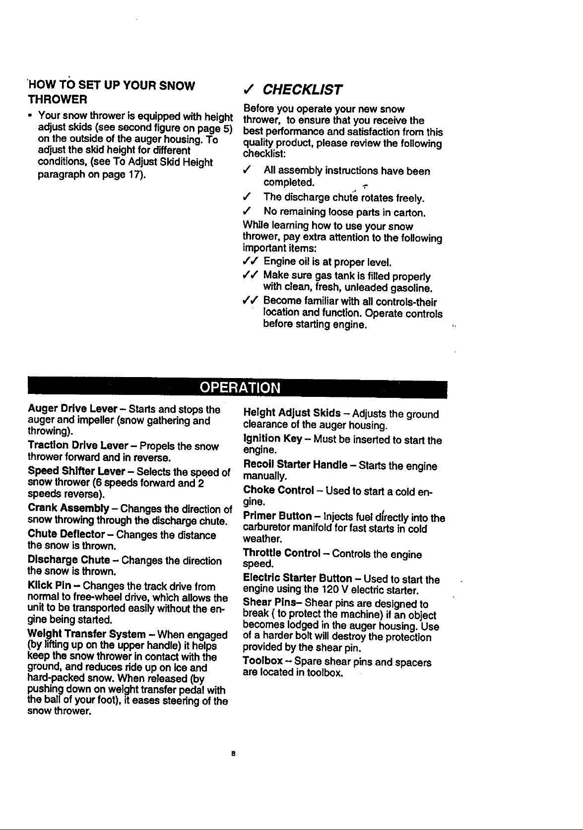
'HOW TO SET UP YOUR SNOW
THROWER
• Your snow thrower is equipped with height
adjust skids (see second figure on page 5)
on the outside of the auger housing. To
adjust the skid height for different
conditions, (see To Adjust Skid Height
paragraph on page 17).
•/ CHECKLIST
Before you operate your new snow
thrower, to ensure that you receive the
best performance and satisfaction from this
quality product, please review the following
checklist:
v" All assembly instructions have been
completed. ..-
/ The discharge chute rotates freely.
,/ No remaining loose parts in carton.
While learning how to use your snow
thrower, pay extra attention to the following
important items:
,/,/ Engine oil is at proper level.
,// Make sure gas tank is filled properly
with clean, fresh, unleaded gasoline.
,/,/ Become familiar with all controls-their
location and function. Operate controls
before starting engine.
Auger Drive Lever- Starts and stops the
auger and impeller (snow gathering and
throwing).
Traction Drive Lever- Propels the snow
thrower forward and in reverse.
Speed Shifter Lever- Selects the speed of
snow thrower (6 speeds forward and 2
speeds reverse).
Crank Assembly - Changes the direction of
snow throwing through the discharge chute.
Chute Deflector - Changes the distance
the snow is thrown.
Discharge Chute - Changes the direction
the snow is thrown.
KIIck Pin - Changes the track drive from
normal to free-wheel drive, which allows the
unit to be transported easily without the en-
gine being started.
Weight Transfer System - When engaged
(by lifting up on the upper handle) it helps
keep the snow thrower in contact with the
ground, and reduces ride up on ice and
hard-packed snow. When roleased (by
pushing down on weight transfer pedal with
the ball of your foot), it eases steering of the
snow thrower.
Helght Adjust Skids - Adjusts the ground
clearance of the auger housing.
Ignition Key - Must be inserted to start the
engine.
Recoil Starter Handle - Starts the engine
manually.
Choke Control - Used to start a cold en-
gine.
Pdmer Button - Injects fuel dfrectly into the
carburetor manifold for fast starts in cold
weather.
Throttle Control - Controls the engine
speed.
Electric Starter Button - Used to start the
engine using the 120 V electric starter.
Shear Pins- Shear pins are designed to
break ( to protect the machine) if an object
becomes lodged in the auger housing. Use
of a harder bolt will destroy the protection
provided by the shear pin.
Toolbox - Spare shear pins and spacers
are located in toolbox.
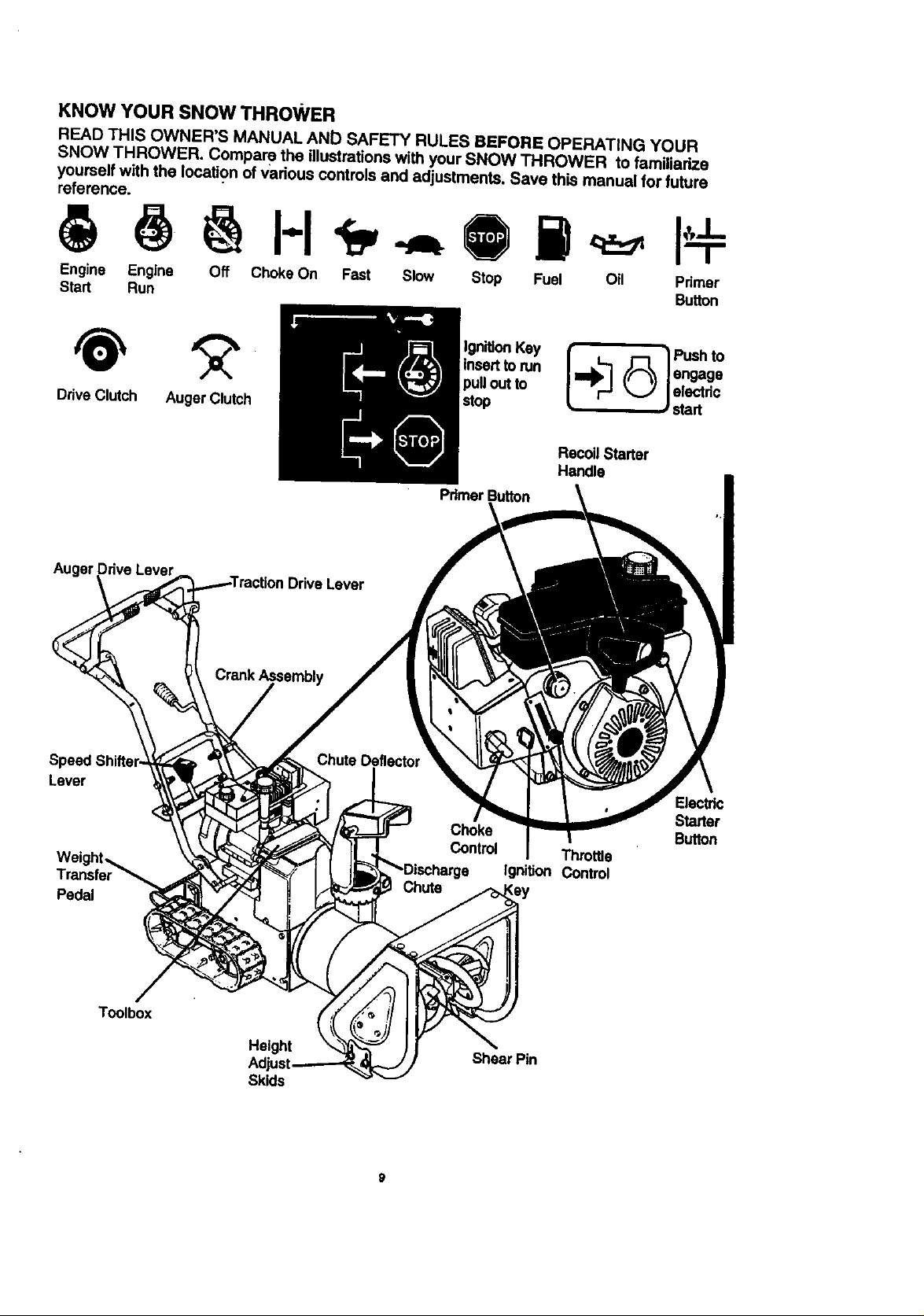
KNOW YOURSNOWTHROWER
READ THIS OWNER'S MANUAL AND SAFETY RULES BEFORE OPERATING YOUR
SNOW THROWER. Compare the illustrations with your SNOW THROWER to familiarize
youmelf with the location of various controls and adjustments. Save this manual for future
reference.
• I-I ,
Engine Engine Off Choke On Fast Slow Stop Fuel Oil
Start Run
insertto run ((_ ] engage
DriveClutch AugerClutch k,...) /electdc
Recoil Starter
Handle
Pdmer Button
Auger Lever
IDriveLever
Pdmer
Button
/start
Lever
Pedal
Toolbox
Height
Skids
Electric
Starter
Button
Throttle
IgniUon Control
Shear Pin

The operation of any snow thrower can re-
.suit in fol'eign objects being thrown into the
eyes, which can result in severe eye dam-
age. Always wear safety glasses or eye
shields while operating the snow thrower.
We recommend standard safety glasses or
a wide vision safety mask for over your
glasses, available at Craftsman Retail
Stores or Service Centers.
A_ CAUTION: Read owner's manual
before operating machine. Never direct
discharge toward bystanders. Release the
auger control bar and stop the engine
before unclogging discharge chute or auger
housing and before leaving the machine.
HOWTO USEYOUR SNOW
THROWER
TO STOPYOUR SNOWTHROWER
• To stop throwing snow, release the auger
drive lever (see last figure on this page).
• To stop the track, release the traction
drive lever (see last figure on this page).
• To stop the engine, push the throttle con-
trol lever to off and pull out (DO NOT
TURN) the ignition key, see figure below.
Ignition Primer Electdc
key
TO MOVE FORWARD AND
BACKWARD
• To shift, release the traction drive lever
and move the speed shifter lever to the
speed you desire. Ground speed is deter-
mined by snow conditions. Select the
speed you desire by moving the speed
shifter lever into the appropriate area on
the speed selector.
Speeds 1, 2 - Wet, Hea_y, Extra Deep
Speed 3 - Light
Speed 4 - Very Light
Speeds 5, 6 - Transport only
• Engage the traction drive lever as shown
in figure below, left hand. As the snow
thrower starts to move, maintain a firm
hold on the handles, and guide the snow
thrower along the clearing path. Do not
attempt to push the snow thrower.
• To move the snow thrower backward,
move the speed shifter lever into first or
second reverse and engage the traction
drive lever (left hand).
IMPORTANT: Never move the speed shifter
lever while the traction lever is down.
TO THROW SNOW
• Push down the auger drive lever, see fig-
ure below.
• Release to stop throwing snow.
Recoilstarter
handle
control
control
TO CONTROL SNOW DISCHARGE
•Tum the crank assembly to set the direc-
tion of the snow throwing.
• Loosen the wing knob on the chute de-
flector and move the deflector to set the
distance. Move the deflector (UP) for
more distance, (DOWN) for less distance.
Then tighten the wing knob, see figure
below.
knob
TractionDrive Lever Auger DriveLever
oft
Lefthand Right hand
TO USE WEIGHT TRANSFER SYS-
TEM
In hard packed or heavy snow conditions,
conventional snow throwers tend to ride up
and leave uneven mounds of snow behind.
For these conditions, your new tracked
snow thrower has a unique weight transfer
system (see first figure on page 11)
designed to minimize ride-up.
The weight transfer system engaged shifts
more weight to the auger housing. This
weight transfer keeps the snow thrower in
contact with the ground and reduces ride-up
on ice and snow.
lO
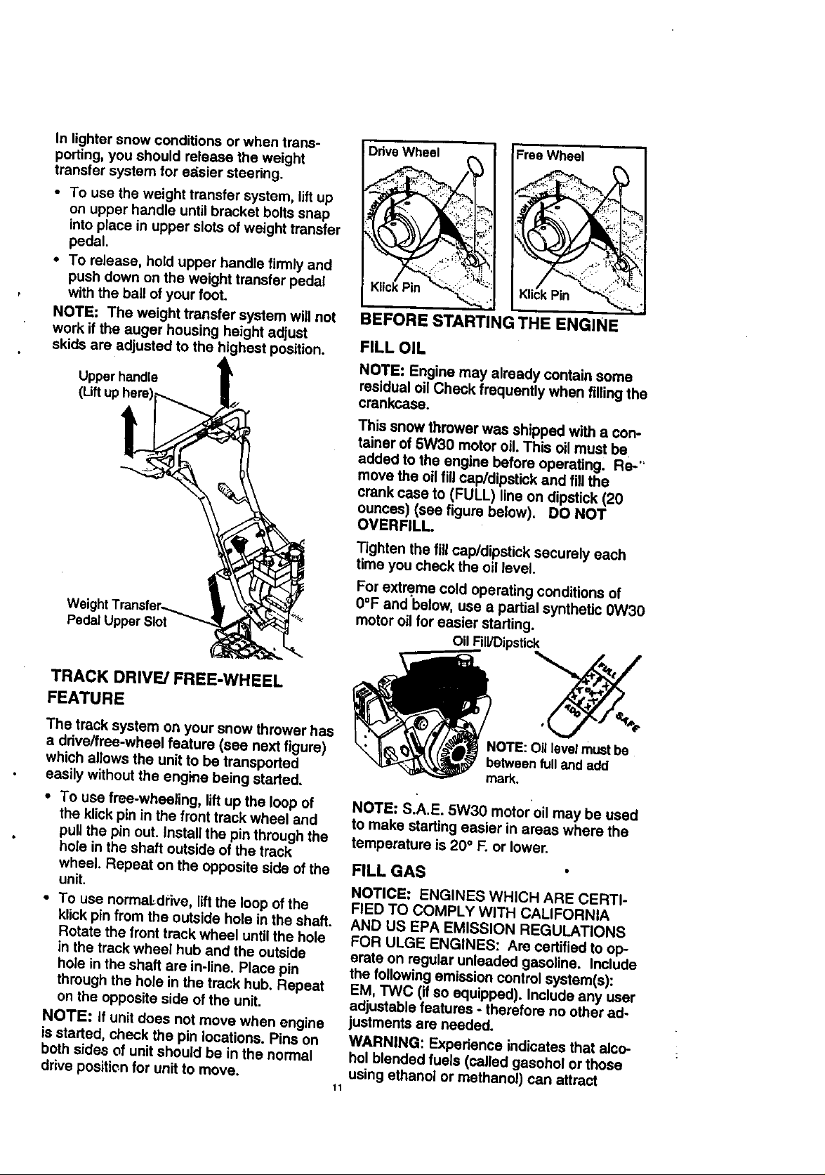
In lighter snow conditions or when trans-
porting, you should release the weight
transter system for edsier steering.
• To use the weight transfer system, lift up
on upper handle until bracket bolts snap
into place in upper slots of weight transfer
pedal.
• To release, hold upper handle firmly and
push down on the weight transfer pedal
with the ball of your foot.
NOTE: The weight transfer system will not
work if the auger housing height adjust
skids are adjusted to the highest position.
Upperhandle
Pedal Upper Slot
i
BEFORE STARTING THE ENGINE
FILL OIL
NOTE: Engine may already contain some
residual oil Check frequently when filling the
crankcase.
This snow thrower was shipped with a con-
tainer of 5W30 motor oil. This oil must be
added to the engine before operating. Re-"
move the oil fill cap/dipstick and fill the
crank case to (FULL) line on dipstick (20
ounces) (see figure below). DO NOT
OVERFILL.
Tighten the fill cap/dipstick securely each
time you check the oil level.
For extreme cold operating conditions of
0°F and below, use a partial synthetic 0W30
motor oilfor easier starting.
Oil FiWDipstick
TRACK DRIVE/FREE-WHEEL
FEATURE
The track system on your snow thrower has
a ddve/free-wheel feature (see next figure)
which allows the unit to be transported
easily without the engine being started.
• To use free-wheeling, lift up the loop of
the kUck pin in the front track wheel and
pull the pin out. Install the pin through the
hole in the shaft outside of the track
wheel. Repeat on the opposite side of the
unit.
• To use normaLdrlve, liftthe loop of the
klick pin from the outside hole in the shaft.
Rotate the front track wheel until the hole
in the track wheel hub and the outside
hole in the shaft are in-line. Place pin
through the hole in the track hub. Repeat
on the opposite side of the unit.
NOTE: If unit does not move when engine
is started, check the pin locations. Pins on
both sides of unit should be in the normal
drive position for unit to move.
_OTE: Oil level must be
between fulland add
mark.
NOTE: S.A.E. 5W30 motor oil may be used
to make starting easier in areas where the
temperature is 20 ° F. or lower.
FILL GAS
NOTICE: ENGINES WHICH ARE CERTI-
FIED TO COMPLY WITH CALIFORNIA
AND US EPA EMISSION REGULATIONS
FOR ULGE ENGINES: Are certified to op-
erate on regular unleaded gasoline. Include
the following emission control system(s):
EM, TWC (if So equipped), include any user
adjustable features - therefore no other ad-
justmants are needed.
WARNING: Experience indicates that alco-
hol blended fuels (called gasohol or those
using ethanol or methanol) can attract
11
moisture which loads to separation and for-
mationof acids during storage. Acidic gas
can damage tho fuel system of an ongine
while in storage.
To avoid engino probloms, the fuol system
should be emptied before storage for 30
days or longer. Star the engino and let it run
until the fuel lines and carburetor are empty.
Use the carburetor bowl drain to empty re-
sidual gasoline from the float chamber. Use
fresh fuel next season (see
Storage instructions on page 23 for addi-
tional information).
Never use engine or carburetor cleaner
products in the fuel tank or permanent dam-
age may occur.
Fill the fuel tank with a fresh, clean, un-
leaded regular, unloaded premium, or
reformulated automotive gasoline only. DO
NOT use leaded gasoline. Be sure that the
container you pour the gasoline from is
clean and free from rust or other foreign par-
ticles. Never use gasoline that may be stale
from long periods of storage in the con-
tainer.
Z_ CAUTION: Gasoline is flammable and
caution must be used when handling or stor-
ing it.
Do not fill fuel tank while snow thrower is
running, when it is hot, or when snow
thrower is in an enclosed area.
Keep away from open flame or an electrical
spark and DO NOT SMOKE while filling the
fuel tank.
NEVER till the tank completely. FILL THE
TANK to within 1/4" - 1/2" from the top to
provide space for expansion of fuel.
Always fill fuel tank outdoors and use a fun-
nel or spout to prevent spilling.
Make sure to wipe up any spilled fuel before
starting the engine.
Store gasoline in a clean, approved con-
tainer and keep the cap in place on the con-
tainer.
TO STOP ENGINE
• To stop engine, move the throttlecontrol
lever to II (STOP) position and remove
key. Keep the key in a safe place. The
engine will not start without the key.
NOTE: DO NOT rum key.
TO START ENGINE (Electric Starter)
Be sure that the engine has sufficient oil.
The snow thrower engine is equipped with a
120 volt A.C. electric starter and recoil
starter. Before starting the engine, be cer-
tain that you have read the following infor-
mation:
COLD START
• Be sure the auger drive and traction drive
levers are in the disengaged (released)
position.
• Move the throttle controRo _ (FAST)
position. See figure on page 9.
• Remove the keys from the plastic bag.
Insert one key into the ignition slot. Be
sure it snaps into place. DO NOT TURN
KEY. Keep the Second key in a safe
place.
• Rotate the choke knob to H choke On
position. See figure on page 9.
• Connect the power cord to the switch box
on the engine.
/_ CAUTION: This starter is equipped
with a three-wire power cord and plug and is
designed to operate on 120vott AC house-
hold current. It must be properly grounded
at all times to avoid the possibility of electri-
cal shock, which may be injurious to opera-
tor. Follow all instructions carefully as set
forth in the "To Start Engine" section. Deter-
mine that your house wiring is a three-wire
grounded system. Ask a licensed electri-
cian if you are not sure. If your house wire
system is not a three-wire system, do not
use this electric starer under any condi-
tions. If your system is grounded and a
three-hole receptacle is not available at the
point your starter will normally I_e used, one
should be installed by a licensed electrician.
When connecting 120 volt AC power cord,
always connect the cord to the switch box
on the engine first, then plug the other end
into the three-hole grounded receptacle.
When disconnecting power cord, always un-
plug the end in the three-hole grounded re-
ceptacle first.
• Plug the other end of the power cord into
a three-hole, grounded 120 volt A.C.
receptacle.
• Push the primer button while covering the
vent hole as follows: (Remove finger
from primer button between primes).
See figure on page 9 for location.
Do not prime if temperature is above
50°F.
Two times if tempersture is 50°F to 15°F.
Four times if temperatlJre is below 15°F.
_2
• Pushdownonthestarterbuttonuntilthe
enginestarts.Donotcrankfor more than
10 seconds at a time. This electric starter
is thermally protected. If Overheated itwill
stop automatically and can be restarted
only when it has cooled to a safe
temperature (a wait of about 5 to 10
minutes is required).
• When the engine starts, release the
starter button and move choke lever to
"1/2 choke" position. When engine runs
smoothly, move choke lever to =No
Choke" Pos!tion.
• Disconnect the power cord from the
receptacle first and then from the switch
box on engine.
NOTE: Allow the engine to warm up for sev-
eral minutes before blowing snow in tem-
peratures below 0°F.
• Run the engine at full throttle ,_ (FAST)
when throwing snow.
TO STOP ENGINE
• To stop engine, move the throttle control
lever to Q (STOP) position and remove
key. Keep the key in a safe place. The
engine will not start without the key.
NOTE: DO NOT turn key.
TO START ENGINE (Recoil Starter)
Be sure that the engine has sufficient oil.
The snow thrower engine is equipped with a
recoil starter. Before starting the engine, be
certain that you have read the following in-
formation:
COLD START
• Be sure the auger drive and traction drive
levers are in the disengaged (released)
position.
• Move the throttle control to '_ (FAST) po-
sition. See figure on page 9 for location.
• Remove the keys from the plastic bag. In-
sert one key into the ignition slot. Be sure
itsnaps into place. DO NOT TURN KEY.
Keep the second key in a safe place.
• Rotate the choke knob to H choke On
position. See figure on page 9.
• Push the primer button, see figure on page
9, while covering the vent hole as fallows:
(Remove finger from primer button be-
tween primes).
Do not prime if temperature is above
50oR
Two times if temperature is 50°F to
15°F.
Four times if temperature is below
15"1:.
• Pull the recoil starter handle rapidly. Do
not allow the handle to snap back, but al-
low it to rewind slowly while keeping a
firm hold on the starter handle.
• As engine starts warms up move choke
lever to "1/2 choke" position. When
engine runs smoothly, move choke lever
to "No Choke" Position.
NOTE: Allow the engine to warm upfor
several minutes before blowing snow in
temperatures below 0°F.
• Run the engine at full throttle ,_p (FAST)
when throwing snow.
WARM START
If restarting a warm engine after a short
shutdown, leave choke at (OFF) and do
not push the primer button. If the engine
fails to start, follow the Cold Start instruc-
tions above.
FROZEN RECOIL STARTER
If the starter Is frozen and will not turn
engine:
• Pull as much rope out of the starter as
possible.
• Release the starter handle and let it snap
back against the starter.
If the starter still fails to tum engine, repeat
the two previous steps until the starter en-
gages. Then continue with the directions for
cold start.
To help prevent possible freeze-up of recoil
starter and engine controls, proceed as fol-
lows after each snow removal job.
• With the engine running, pull the starter
rope hard with a continuous full arm
stroke three or four times. Pulling of
starter rope will produce a loud clattering
sound. This is not harmful to the engine
or starter.
• With the engine net running, wipe all
snowand moisture fromthe carburetor
coverin area ofcontrollevers.Alsomove
throttlecontrol,choke control,and starter
handle several times.
13
 Loading...