

Craftsman 536.886621 Owner's Manual
IMPORTANT MANUAL DO NOT THROW AWAY
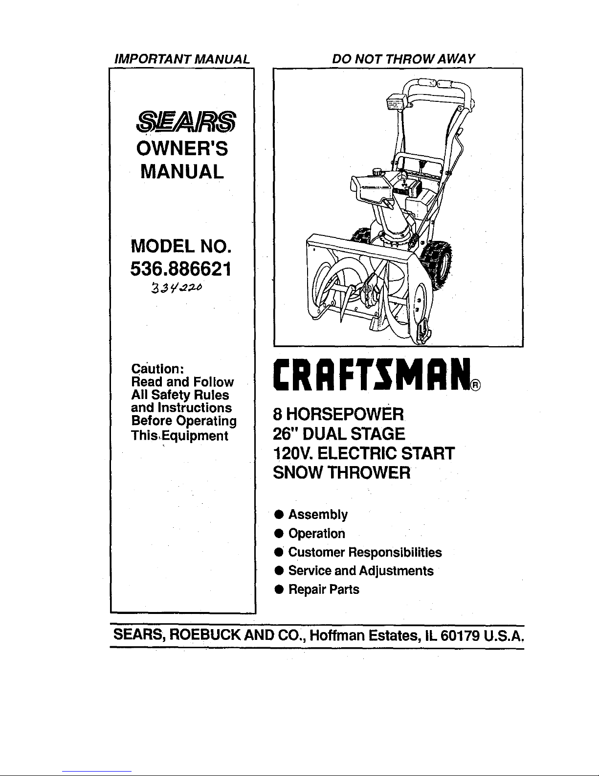
OWNER'S
MANUAL
MODEL NO.
536.886621
caution:
Read and Follow
All Safety Rules
and Instructions
Before Operating
This,Equipment
CRRFTSMRN®
8 HORSEPOWER
26" DUAL STAGE
120V. ELECTRIC START
SNOW THROWER
• Assembly
• Operation
• Customer Responsibilities
• Service and Adjustments
• Repair Parts
SEARS, ROEBUCK AND CO., Hoffman Estates, IL 60179 U.S.A.
SAFETY RULES
CAUTION: ALWAYS DISCONNECT SPARK PLUG WIRE AND
A A
,L PLACE WIRE WHERE IT CANNOTt CONTACT SPARK PLUG AL
TOPREVENTAOO,DENTALSTART.NGW.ENSETT,.GUP
TRANSPORT,N ADJUST,N ORMAK,N REPA,RS
IMPORTANT
SAFETY STANDARDS REQUIRE OPERATOR PRESENCE CONTROLS TO MINIMIZE THE
RISK OF INJURY. YOUR SNOW THROWER IS EQUIPPED WITH SUCH CONTROLS. DO NOT
AI-FEMPT TO DEFEAT THE FUNCTION OF THE OPERATOR PRESENCE CONTROL UNDER
ANY CIRCUMSTANCES.
TRAINING
1.
Read the operator's manual carefully. Be
thoroughly familiar with the controls and the
proper use of the snow thrower. Know how to
stop the snow thrower and disengage the
controls quickly.
2. Never allow children to operate the snow thrower
and keep them away while It Is operating. Never
allow adults to operate the snow thrower without
proper Instruction. DO not carry passengers.
3. Keep the area of operetlon clear of all persons,
particularly small children, and pets.
4. Exercise caution to avoid slipping or falling,
especially when operating In reverse.
PREPARATION
1. Thoroughly Inspect the area where the snow
thrower Is to be usedand removeall doormats,
sleds, boards,wires, and otherforeignobjects.
2. Disengage all clutches and shift Into neutral
before startingtheengine (motor).
3. Donotoperetethe snowthrowerwithoutweadng
adequate winterouter garments.Wearfootwear
that will Improvefootingon slipperysurfacse.
4. Handlefuel wIthcare; it Is highlyflammable.
(a) Use an approvedfuel container.
(b) Never removefuel tank cap or add fuel to a
runningengineor hotengine.
(c) Fill fuel tank outdoors with extreme care,
Never fillfueltank Indoors.
(d) Replace fuel tank cap securely and wipe up
spilled fuel.
(e) Never store fuel or snow thrower with fuel In
the tank Inside ofa building where fumes may
reach an open flame or spark.
(f) Check fuelsupplybefore each use,anowlng
spaceforexpenslonastheheatofthe engine
(motor)and/or suncan causefuel toexpend.
5. Useextsnsloncordssnd racaptaclesasspecified
by the manufacturerfor all snowthrowerswith
eiactrlc drivemotors orelectricstartingmotors.
6. Adjust the snow thrower height to clear gravel or
crushed rock surfaces,
7. Never aftempt to make any edjustmsnts while the
engine (motor) Is running (except when
specifically recommended by the manufacturer).
8. Let engine (motor) and snow thrower adjust to
outdoor temperatures before starting to clear
SNOW.
9. Always weer safety glasees or eye shields during
operetlon or while performing an adjustment or
repair to protect eyes from foreign objects that
may be thrown from the snow thrower.
OPERATION
1. Do not put hands or feet near or underrotating
parts. Keepclear of thedischarge openingatall
times.
2. Exercise extreme cautio n when operating on or
crossing gravel drives, walks, or roads. Stay alert
for hidden hazards or traffic.
3. After striking a foreign object, stop the engine
(motor), remove the wire from the spark plug,
disconnect the cord on electric motors,
thoroughly Inspect the snow thrower for any
damage, and repair the damage before restarting
and operating the snow thrower.
4. If the snow thrower should start to vibrate
abnormally, stop the (motor) and check
Immediately forthe cause. Vlbretlon Is gsnerelly
a warning of trouble.
5. Stop the snglne (motor) wheheveryou leavethe
operating position, before unclogging the auger/
Impeller housing or dlsnherge guide, and when
making a nyrepairs, adjustments, or Inspections.
6. When cleaning, repairing, or Inspecting, make
cartaln the auger/impeller and all moving parts
have stopped. Disconnect the spark plug wire
and keep the wire away from the plug to prevent
accidental starting.
7. Take all possible precautions when leaving the
snow thrower unattended. Disengage the auger/
Impeller, shift to neutral, stop engine, and
remove key.
2
SAFETY RULES
8. DOnot runthe engine indoors, except when starting
the engine and fortransporting thesnow throwerIn
or out of the building. Open the outside doors;
exhaust fumes aredangerous (containing CARBON
MONOXIDE, an ODORLESS and DEADLY GAS).
9. Do not clear snow across the face of slopes.
Exercise caution when changing direction on
slopes. Do not attempt to clear steep slopes.
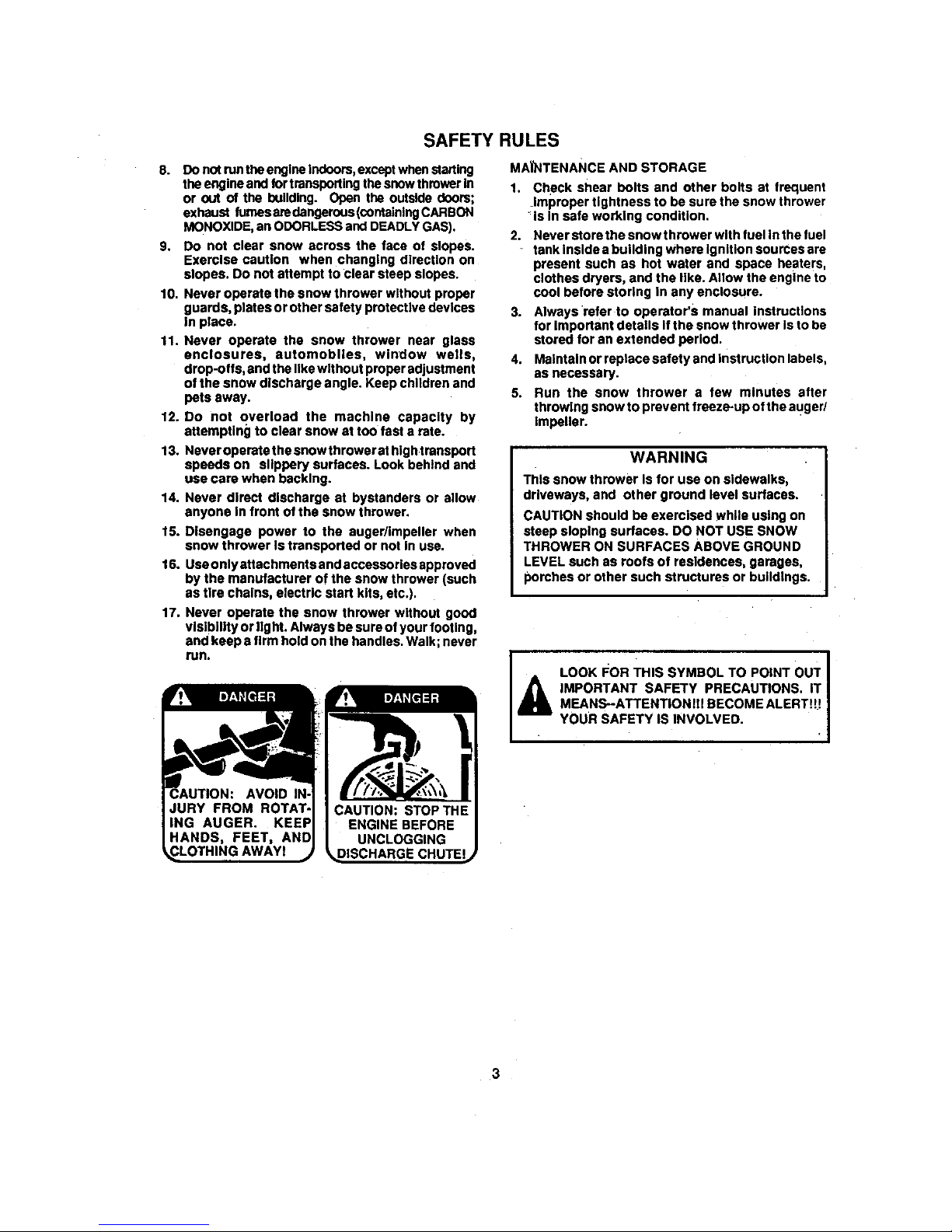
10. Never operate the snow thrower without proper
guards, plates or other safety protective devices
In place.
11. Never operate the snow thrower near glass
enclosures, automobiles, window wells,
drop-offs, and the like wit hour proper adjustment
of the snow discharge angle. Keep children and
pets away.
12. Do not overload the machine capacity by
attempting to clear snow at too fast a rate.
13. Neveroperatethesnowthrowerat hlghtransport
speeds on slippery surfaces. Look behind and
use care when becking.
14. Never direct dlscherge at bystanders or allow
anyone In front of the snow thrower.
15. Disengage power to the augerllmpeller when
snow thrower Is transported or not In use.
16. Use only sttachments and accessories approved
by the manufacturer of the snow thrower (such
as tire chains, electric start kits, etc.).
17. Never operate the snow thrower without good
vlslblnty or light. Always be sure of your footing,
and keep a firm hold on the handles. Walk; never
run.
MAI'NTENANCE AND STORAGE
1. Check shear bolts and other bolts at frequent
improper tightness to be sure the snow thrower
is In safe working condition.
2. Never store the snow thrower with fuel in the fuel
tank inside a building whers Ignition sourcee are
present such as hot water and space heaters,
clothes dryers, and the llke. Allow the engine to
cool before storing In any enclosure.
3. Always •refer to operator's manual instructions
for Important details If the snow thrower is to be
stored for an extended period.
4. Maintain or replace safety and Instruction labels,
as necessary.
5. Run the snow thrower a few minutes after
throwing snow to prevent freeze-up of the auger/
impeller.
WARNING
This snow thrower Is for use on sidewalks,
driveways, and other ground level surfaces.
CAUTION should be exercised while using on
steep sloping surfaces. DO NOT USE SNOW
THROWER ON SURFACES ABOVE GROUND
LEVEL such as roofs of residences, garages,
porches or other such structures or buildings.
II_ LOOK I_OR THIS SYMBOL TO POINT ouT
I
A
IMPORTANT SAFETY PRECAUTIONS. IT I
MEANS--ATTENTIONll! BECOME ALERTt!!
YOUR SAFETY IS INVOLVED.
3
TABLE OF CONTENTS.
SAFETY RU LES ........................................ 2,3
PRODUCT SPECIFICATIONS ...................... 4
CUSTOMER RESPONSIBILITIES ..... 4,16-18
WARRANTY ................................................. 4
TABLE OF CONTENTS .............................. 5
INDEX ........................................................... 5
ASSEMBLY ................................................ 6-9
OPERATION .......................................... 10-15
SERVICE AND ADJUSTMENTS ........... 19-25
S'_ORAGE ................................................... 26
TROUBLE SHOOTING ............................... 27
REPAIR PARTS CSNOW THROWER)...28-38
REPAIR PARTS (ENGINEI .................... 39-42
PARTS ORDERING/SERVICE ................... 44
A
Adjustment:
Auger ............................................. 24
Belts............................................... 20
Belt Guide...................................... 22
Cable ............................................. 20
Carburetor ..................................... 24
FrictionWheel ................................ 22
Spark Plug...;................................. 25
Traction and Auger........................ 20
Assembly:
Check List ........................................ g
Crank Assembly .............................. 8
Headlight......................................... 9
Skid HeightAdjustment .............7, 19
Unpacking........................................ 7
B
Belts:
AdjustBelts.................................... 20
Belt Guide Adjustment................... 22
Belt Maintenance..................... 20, 21
Replace Belts ..;................ :............ 20
C
Cables. Clutch.......................... 7. 9, 20
Carburetor:................................. 24, 26
Choke ........._.................... t0, 1t, 13,14
Clutch, Auger................... 1O, 11, 13,14
Clutch, Traction............... 10, 11, 13,14
Controls:
Engine .......................... 10, 11, 13,14
Snow Thrower ........................ 10. 11
Crank:
AdjustingRod ............................ 8, 19
Assembly......................................... 8
Operation........................................ 10
Customer Responsibilities........4.16-18
Agreement....................................... 4
Auger Gear Box ............................ 18
Auger Shaft................................... 17
Engine ........................................... 18
General Recommendations.......... 16
Hex Shaft and Gears................ 17-18
Spark Plug..................................... 18
O
Deflector, SnowChute ......... I0. t 1.15
E
ElectricStarter................................. 13
Engine:
Control .................... 10. 11, 13, 14,15
Oil CaD.............. "...................... 12. 18
OilChange ..................................... 18
INDEX
Oil Level ............................. L.... 12, 18
• OilType ............................... _. 12. 18
Speed Governor ............................ 24
Starting the Engine ................... 13,14
Storage ........................... :.............. 26
F
Fuel, Type .................................... 4, 12
Fuel. Storage .............................. 13, 26
Friction Wheel:
Adjustment ..................................... 22
Replacement ................................. 23
G
Gears:
Auger Gear Box ............................. 18
Hex Shaft ....................................... 18
H
Handle, Upperand Lower .................. 7
Headlight............................................. 9
Height AdjustSkids ...................... 7. 19
Hex Shaft ......................................... 18
I
Ignition,Key..................... 10. 11, 13,14
Index .........:........................................ 5
L
Levers:
Auger DriveClutch ........7, 10, 11, 17
Choke ........................... 10, 11, 13,14
Shifter ...................................... 10, 11
Throttle Control ............ 10, 11.13, 14
TractionDrive Clutch..... 7, 10, 11, 14
Lubrication:
Auger Gear Box........................ 17-18
Auger Shaft.................................... 17
DiscDrive Plate............................. 18
Engine ........................................... 18
• Hex Shaft and Gears ............... :..... 17
O
Oil:
Engine ................................. 4, 12, 18
Extreme Cold Weather ............. 12,18
Storage ..................................... ;.._26
Type..................................... 4.12, 18
Operation:
Engine Controls ............ 10. 11.13,14
LockoutPin. Wheel........................ 12
Operating Snow Thrower...................
....................................... 10, 11.13,14
Snow ThrowingTips ...................... 15
Starting theEngine ................... 13.14
Snow Throwar Controls........... 10.11
P
Parts............................................ 28-41
Primer Button.................. 10,11, 13,14
R
Repair/Replacement Parts .......... 28-42
Recoil Starter ................................... 14
Replacements:
Auger Shear Bolt...................... .....24
Belts............................................... 20
FrictionWheel ............................... 22
S
Safety Rules ................................... 2. 3
Service and Adjustments:
Auger HousingHeight ............... 7, 19
Auger Shear Bolt........................... 24
Belts......................................... 20. 21
Belt Guide ....................... ...............22
Belt Replacement .......................... 21
Cable ..................................... 7. g, 20
Carburetor ............................... 24, 26
Chute Crank .................................. 19
FrictionWheel .......................... 22, 23
Scraper Bar ................................... 19
Spark Plug ..................................... 25
Service Recommendations .............. 27
Spark Plug .................................. 18, 25
Specifications ..................................... 4
Speed Governor ............................... 24
Startingthe Engine ...................... 13,14
Stopping the Engine ................... 11, 13
Stopping the Snow Thrower ............. t 1
Shipping Carton .............. ................ 6, 7
Skid Height ................................... 7, 19
Shifter Lever ................................ 10.11
Shear Bolts....................................... 24
Storage ............................................. 26
T
Table of Contents............................... 5
Tire Pressure.................................... 19
Trouble Shooting Chart .................... 27
Tools for Assembly ............................. 6
Traction Drive Belt.................. ..... 20,21
W
Warranty ............................................. 4
Wheel. Lockout Pin .......................... 12
5
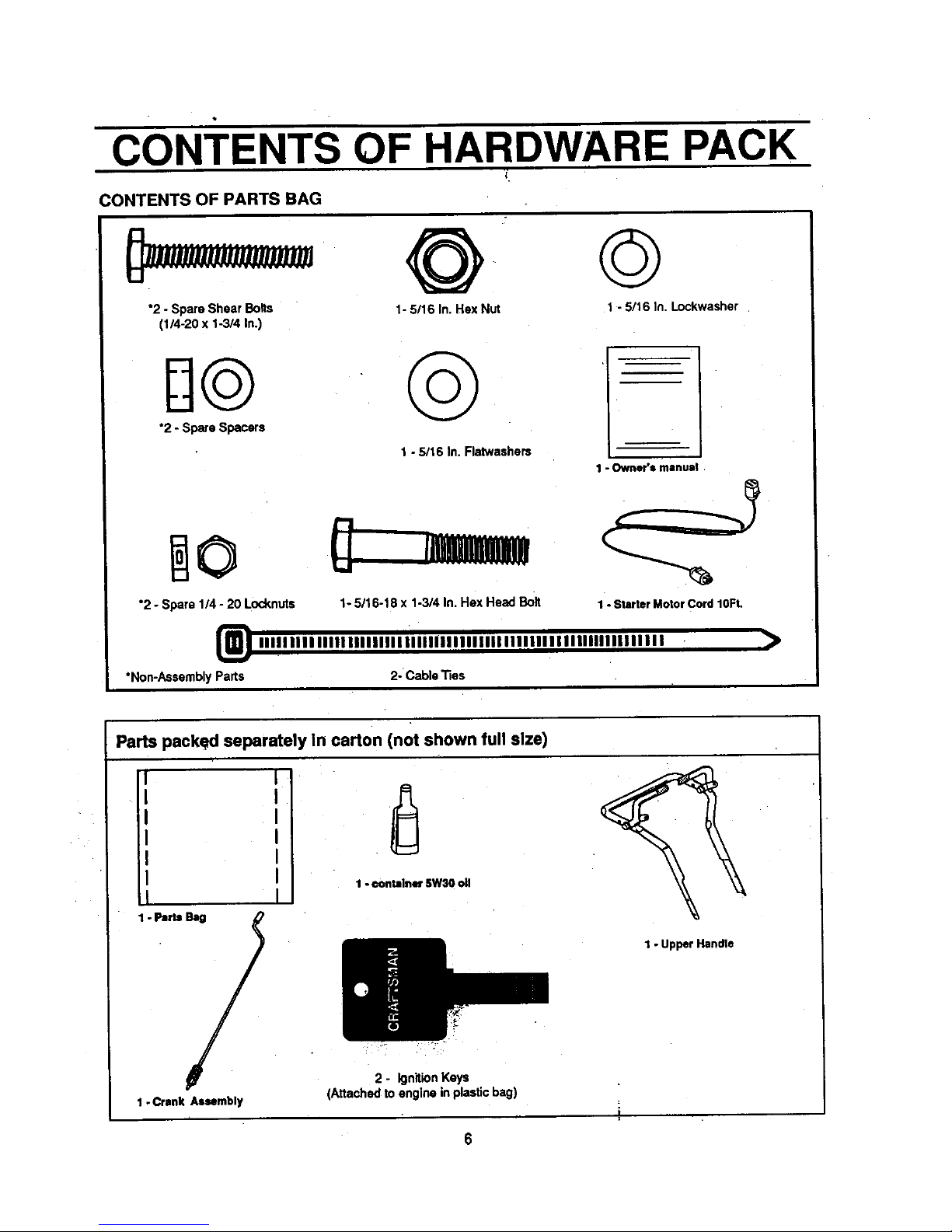
CONTENTS OF HARDWARE PACK
:ONTENTS OF PARTS BAG
"2 - Spare Shear Bolts
(1/4-20 x 1-3/4 in.)
@ ©
1- 5/16 In. Hex Nut
1 - 5/16 In. Lockwasher
H@ @
*2 - Spare Spacers
1 -5/16 In. Flatwashers
*2 - Spare 114- 20 Locknuts
*Non-Assembly Parts
1 "Owner's manual
1- 5/16-18 x 1-3/4 In. Hex Head Bolt
iiIIIIIn iiinlllllllllllllllllllllllll II IIIIIIIInlllllllllllll
2- Cable _es
1 -Starter Moto! Cord 10Ft.
>
Parts packed separately In carton (not shown full size)
I I
I
I
I
I
I
I
1-Parts _
1-Crank Assembly
1- €ontainer5W30 oli
2 - IgnitionKeys
(Attached to engine inplastic bag)
1 - UpperHandle
6
SERVICE AND ADJUSTMENTS
CAUTION: ALWAYS DISCONNECTTHE
SPARK PLUG WIRE AND TIE BACK
AWAY FROMTHE PLUG BEFORE MAK-
ING ANY ADJUSTMENTS OR REPAIRS.
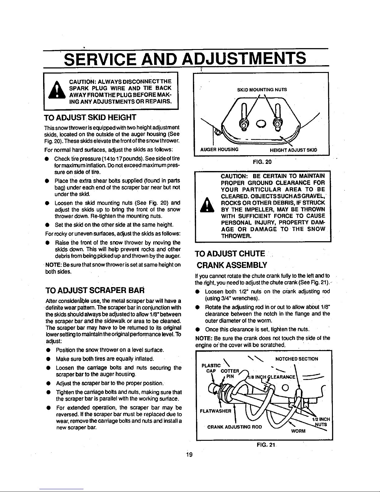
TO ADJUST SKID HEIGHT
Thissnowthroweris equippedwithtwoheightadjustment
skids,located onthe outsideof the auger housing(See
Fig.20).These skidselevatethefront ofthesnowthrower.
For normalhardsudaces, adjustthe skids as follows:
• Check tirepressure(14to17 pounds).See sideoftire
formaximuminflation.Donotexceedmaximumpres-
sureon sideof tire.
• Place the extra shear boltssupplied(found in parts
bag) undereach end of thescraperbar near but not
underthe skid.
• Loosen the skid mountingnuts (See Fig. 20) and
adjustthe skids up to bring the front of the snow
throwerdown. Re-tightenthe mounting nuts.
• Set the skid on the othersideat the same height.
Forrockyoruneven surfaces,adjustthe skidsasfollows:
• Raise the frontof the snowthrower by movingthe
skids down.This will help prevent rocks and other
debrisfrombeingpickedup andthrownbythe auger.
NOTE: Besurethatsnowthrowerissetat sameheighton
both sides.
TOADJUSTSCRAPER BAR
Afterconsiderableuse,the metal scraper bar willhave a
definitewear pattern. The scraperbar inconjunctionwith
theskids shouldalwaysbe adjustedtoallow1/8"between
the scraperbar and the sidewalkor area to be cleaned.
The scraper bar may have to be returned to itsoriginal
lowersettingtomaintaintheoriginalperformancelevel.To
adjust:
• Positionthe snowthroweron a level sudace.
• Make sureboth tiresare equallyinflated.
• Loosen the carriage bolts and nuts securing the
scraperbar tothe augerhousing.
• Adjustthe scraper bar tothe properposition.
• Tightenthecarriagebolts and nuts,makingsurethat
the scraperbar is parallelwiththe workingsurface.
For extended operation, the scraper bar may be
reversed. Ifthe scraper barmust be replaceddue to
wear,removethecarriage bolts andnutsandinstalla
newscraperbar.
SKID MOUNTING NUTS
AUGER HOUSING
HEIGHTADJUSTSKID
FIG. 20
A
CAUTION: BE CERTAIN TO MAINTAIN
PROPER GROUND CLEARANCE FOR
YOUR PARTICULAR AREA TO BE
CLEARED. OBJECTSSUCH ASGRAVEL,
ROCKS OR OTHER DEBRIS, IF STRUCK
BY THE IMPELLER, MAY BE THROWN
WITH SUFFICIENT FORCE TO CAUSE
PERSONAL INJURY, PROPERTY DAM-
AGE OR DAMAGE TO THE SNOW
THROWER.
TO ADJUST CHUTE
CRANK ASSEMBLY
Ifyou cannot rotatethe chutecrankfully tothe leftandto
thedght,youneedto adjustthechutecrank(See Fig.21).
• Loosen both 1/2" nuts on the crank adjustingrod
(using3/4" wrenches).
• Rotatethe adjustingrod inor outto allowabout1/8"
clearancebetween the notch in the flange and the
outerdiameter ofthe worm.
• Once thisclearance isset, tigtltenthe nuts.
NOTE: Be surethe crankdoes not touchthe sideofthe
engineor the coverwillbe scratched.
_ NOTCHED SECTION
PLASTIC
CAP COTTER "_-
FLATWASHER
CRANK ADJUSTING ROD
WORM
1/2 INCH
FIG, 21
i9
SERVICE AND ADJUSTMENTS
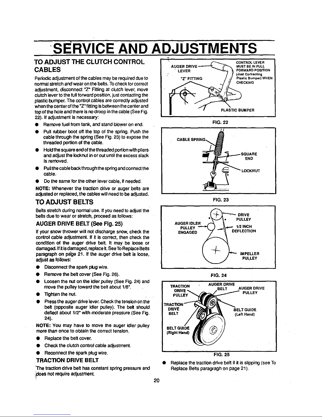
TO ADJUST THE CLUTCH CONTROL
CABLES
Periodic adjustmentofthe cables may be required dueto
normalstretch andwear onthe belts. Tocheckfor correct
adjustment, disconnect "Z" Fittingat clutch lever, move
clutch lever to the fullforward position, just contactingthe
plastic bumper. The control cablesarecorrectly adjusted
when the centerofthe "Z"fittingisbetween the centerand
top ofthe hole and there is no droop in thecable (See Fig.
22). If adjustment is necessary:
• Remove fuel from tank, and stand blo_'er on end.
• Pull rubber boot off the top of the spring. Push the
cablethrough the spring(See Fig. 23)toexposethe
threaded portionof thecable.
• Holdthe squareendofthethreadedportionwithpliers
and adjustthe Iocknutinoroutuntiltheexcessslack
isremoved.
• PuUthe cableback thmughthe springandconnectthe
cable.
• Do the same for theother levercable, ifneeded•
NOTE" Whenever the traction drive or auger belts are
adjusted or replaced, the cableswill needto be adjusted.
TO ADJUST BELTS
Beltsstretchduring normal use. If you needto adjustthe
beltsdue to wear or stretch, proceedas follows:
AUGER DRIVE BELT (See Fig. 25)
Ifyour snow thrower will not dischargesnow,check the
control cable adjustment.If it is correct, then checkthe
condition of the auger drive belt. It may be loose or
damaged.Ifit isdamaged,replaceit.SeeToReplaceBelts
paragraph on p_ge 21. If the auger drive belt is loose,
adjust as follows:
• Disconnectthe sparkplugwire.
• Remove the beltcover (See Fig.26).
• Loosenthe nuton the idlerpulley (See Fig. 24) and
movethe pulleytoward the belt about1/8".
• TKjhtenthe nut.
• Pressthe augerdrive lever.Checkthetensiononthe
belt (opposite auger idler pulley). The belt should
deflect about 1/2" withmoderate pressure(See Fig.
24).
NOTE: You may have to move the auger idler.pulley
mere than once to obtain the correcttension.
• Replacethe belt cover.
• Check the clutchcontrolcable adjustment.
• Reconnectthe sparkplugwire.
TRACTION DRIVE BELT
The tractiondrive belt hasconstantspringpressure and
_doesnot requireadjustment.
2O
•.UGEn0.,VE .
' LEVER _'_ _1 FORWARDPOSITION
.T _ (Just Contacting
"Z"FITTING / ,_ PlaslicBumper)WHEN
| "I- P ,,oau.PEn
FIG. 22
i
OAaLESPR,NG\L
.__ LOCKNUT
FIG. 23
ii
_ DRIVE
_'_-,,/_ • PULLEY
AUGER DLER _ ,_
PULLEY "_ )_..._"" 1/2 INCH
ENGAGED _ i EFLECTION
_, : /"-" IMPELLER
_ PULLEY
FIG. 24
FIG. 25
• Replacethe tractiondrive beltif it isslipping(seeTo
Replace Beltsparagraghon page21).
SERVICE AND ADJUSTMENTS
t
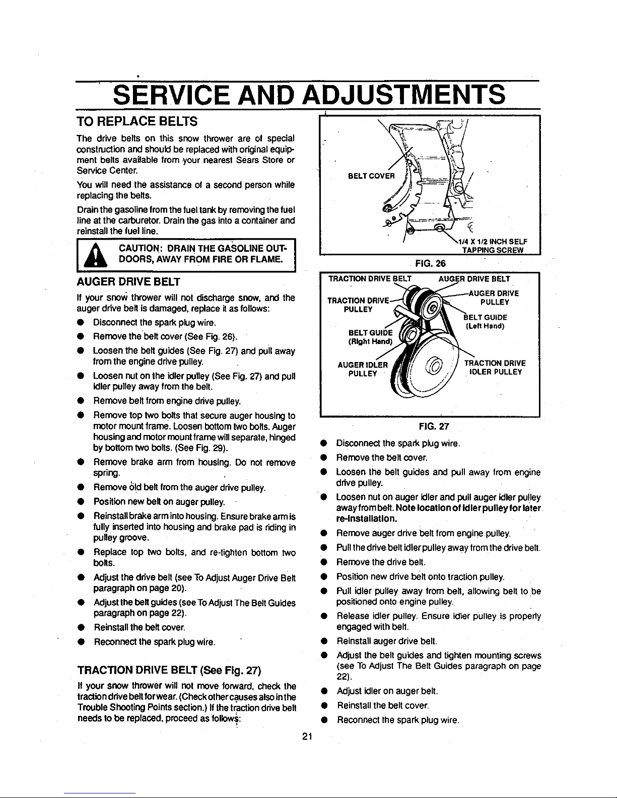
TO REPLACE BELTS \
The drive belts on this snow thrower are ot special
constructionandshould bereplacedwithoriginalequip-
ment belts available from your nearestSears Store or
Service Center.
You will need the assistanceof a secondpersonwhile
replacingthebelts.
Drainthe gasolinefromthe fueltar¢_byremovingthefuel
line atthe carburetor.Drainthegas intoa containerand
reinstallthe fuelline.
BELT COVER /
IA CAUTION: DRAIN THE GASOLINE OUT" I
DOORS, AWAYFROM FIRE OR FLAME.
AUGER DRIVE BELT
If your snow throwerwill not dischargesnow,and the
augerdrive beltis damaged, replaceitas follows:
• Disconnectthe sparkplugwire.
• Removethebelt cover (See Fig. 26).
• Loosen the belt guides (See Fig. 27) and puil away
from the enginedrivepulley.
• Loosen nuton the idlerpulley(See Fig.27) and pull
idlerpulleyaway from thebelt.
Remove beltfrom enginedrivepulley.
Remove toptwo boltsthat secureauger housingto
motormount frame. Loosenbottom two bolts.Auger
housingand motormount framewillseparate,hinged
by bottom two bolts. (See Fig. 29).
• Remove brake arm from housing.Do not remove
spring.
• Remove bid belt fromthe augerdrivepulley.
• Positionnewbelton augerpulley.
• Reinstallbrakearmintohousing.Ensurebrakearmis
fullyinsertedinto housingandbrakepad isriding in
pulleygroove.
• Replace top two bolts, and re-tightenbottom two
bolts.
• Adjustthe drive belt(seeToAdjust Auger DriveBelt
paragraphon page20).
• Adjustthe beltguides(seeToAdjustThe BeltGuides
paragraphon page22).
• Reinstallthe belt cover.
• Reconnectthe sparkplugwipe.
TRACTION DRIVE BELT (See Fig. 27)
If your snow throwerwill not move forward, check the
tractionddvebeltforwear.(Checkotherc.ausesalsointhe
TroubleShootingPointssection.)If thetractiondrivebelt
needsto be replaced,proceedas follows:
TAPPINGSCREW
FIG. 26
AUGERDRIVE BELTTRACTIONDRIVEBELT
PULLEY
PULLEY
BELTGUIDE
(Left Hand)
BELTGUIDE
(Right Hand)
AUGER IDLER TRACTION DRIVE
PULLEY IDLER PULLEY
FIG. 27
Disconnectthe sparkplugwire.
Remove the beltcover,
Loosen the belt guides and pull away from engine
drivepulley.
Loosennuton auger idlerand pullauger idlerpu!ley
awayfrombelt.Note locationof Idler pulley for later
re-Installation.
Remove augerdrivebeltfrom enginepulley,
Pullthedrivebeltidlerpulleyawayfrom thedrivebelt.
Removethe drivebelt,
Positionnew drivebelt onto tractionpulley.
Pullidler pulley away from belt, allowing belt tobe
positioned onto engine pulley.
Release idler pulley. Ensure idler pulley isproperly
engaged with belt.
Reinstall augerdrive belt.
Adjust the belt guidesand tighten mounting screws
(see To Adjust The Belt Guides paragraph on page
22).
Adjust idleron auger belt.
Reinstall the belt cover.
Reconnect the spark plug wire.
21
SERVICE AND ADJUSTMENTS
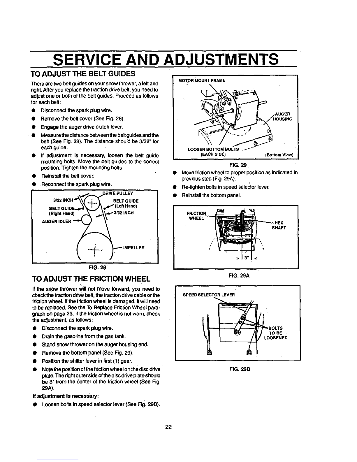
TO ADJUST THE BELT GUIDES
There aretwo beltguidesonyoursnowthrower, a leftand
right.Afteryou replacethe traction drivebelt, youneed to
adjust one or bothof the beltguides. Proceedas follows
for each bolt:
• Disconnectthe spark plugwire.
Removethe bolt cover (See Fig. 26).
Engagethe auger driveclutchlever.
Measurethe distancebotween thebeltguidesendthe
belt (See Fig. 28). The distanceshouldbe 3/32" for
each guide.
• If adjustment is necessary, loosen the belt guide
mountingbolts. Move the belt guidesto the correct
position.Tightenthe mounting bolts.
• Reinstallthe bolt cover.
• Reconnectthe sparkplugwire.
eEL'
(Right Hand)
BELTGUIDE
FIG. 28
TO ADJUST THE FRICTION WHEEL
If the snow thrower_11not move forward,you need to
check the tractionddvebolt, thetractiondrivecable orthe
frictionwheel. Ifthefrictionwheel isdamaged, itwill need
to be replaced, See theTo Replace FdctionWheel para-
graph onpage 23. Ifthe fdctionwheel is notworn, check
the adjustment,as follows:
• Disconnectthe sparkplugwire.
• Drainthe gasolinefrom thegas tank.
• Stand snow throweronthe auger housingend.
• Remove the bottompanel (See Fig. 29).
• Positionthe shitterlever in first(1)gear.
Notethepositionofthefdctionwheelon thediscdrive
plate,The dghtoutersideofthe discdriveplateshould
be 3" from the center of the tdctionwheel (See Fig.
29A).
If adjustment is necessary:
• Loosen bolts in speed selectorlever(See Fig. 29B).
MOTOR MOUNT FRAME
LOOSEN BO'R'OM BOLTS .
(EACH SIDE) (Bottom View)
FIG. 29
• Move frictionwheel toproperpositionasindicatedin
previousstep(Fig.29A).
• Re-tightenboltsinspeedselector lever.
• Reinstallthebottompanel.
FRICTION
SHAFT
/
FIG. 29A
SPEED SELECTOR LEVER
FIG. 29B
22
 Loading...