

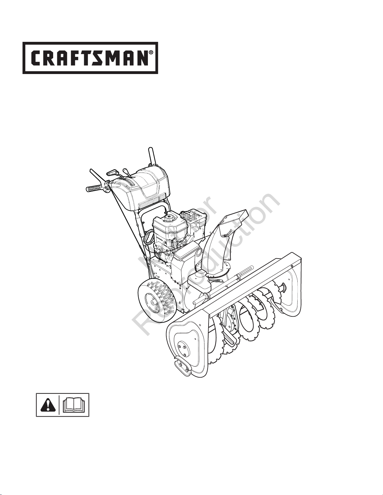
Craftsman 536.886180 Operator's Manual
Operator’s Manual
Not for
Reproduction
Dual Stage Snowthrower
Model No.
536.886180 (9.0 TP Briggs & Stratton with 27-Inch Clearing Width)
For answers to your questions about this
product, call Sears Craftsman Help Line
1-800-659-5917.
Sears Brands Management Corporation, Ho man Estates, IL 60179 U.S.A.
Visit our Craftsman website: www.craftsman.com
1753910
Revision A

Not for
Reproduction
2

TABLE OF CONTENTS
Not for
Reproduction
Front Cover .................................................................................................................1
Operator Safety ..........................................................................................................4
Features and Controls .............................................................................................10
Operation ..................................................................................................................12
Snowthrower Safety Tests .......................................................................................12
Maintenance .............................................................................................................19
Troubleshooting .......................................................................................................24
Speci cations ...........................................................................................................26
Warranty ....................................................................................................................27
Repair Protection Agreement..................................................................................28
Service Parts .......................................................................................................PTS-1
General Information
Thank you for purchasing this quality-built CRAFTSMAN snowthrower. We’re pleased that you’ve placed your con dence in the
CRAFTSMAN brand. When operated and maintained according to the instructions in this manual, your CRAFTSMAN product will
provide many years of dependable service.
This manual contains safety information to make you aware of the hazards and risks associated with snowthrowers and how
to avoid them. This snowthrower is designed and intended only for snow throwing and is not intended for any other purpose. It is
important that you read and understand these instructions throroughly before attempting to start or operate this equipment. Save
these instructions for future reference.
Product Reference Data
When contacting your authorized dealer for replacment parts, service, or information you MUST have these numbers.
Snowthrower
Revision __________
Serial Number ______________________________
Engine
Date Purchased ____________________
Model Number _________________________
Model Number
Revision __________
Serial Number ______________________________
_________________________
en
3
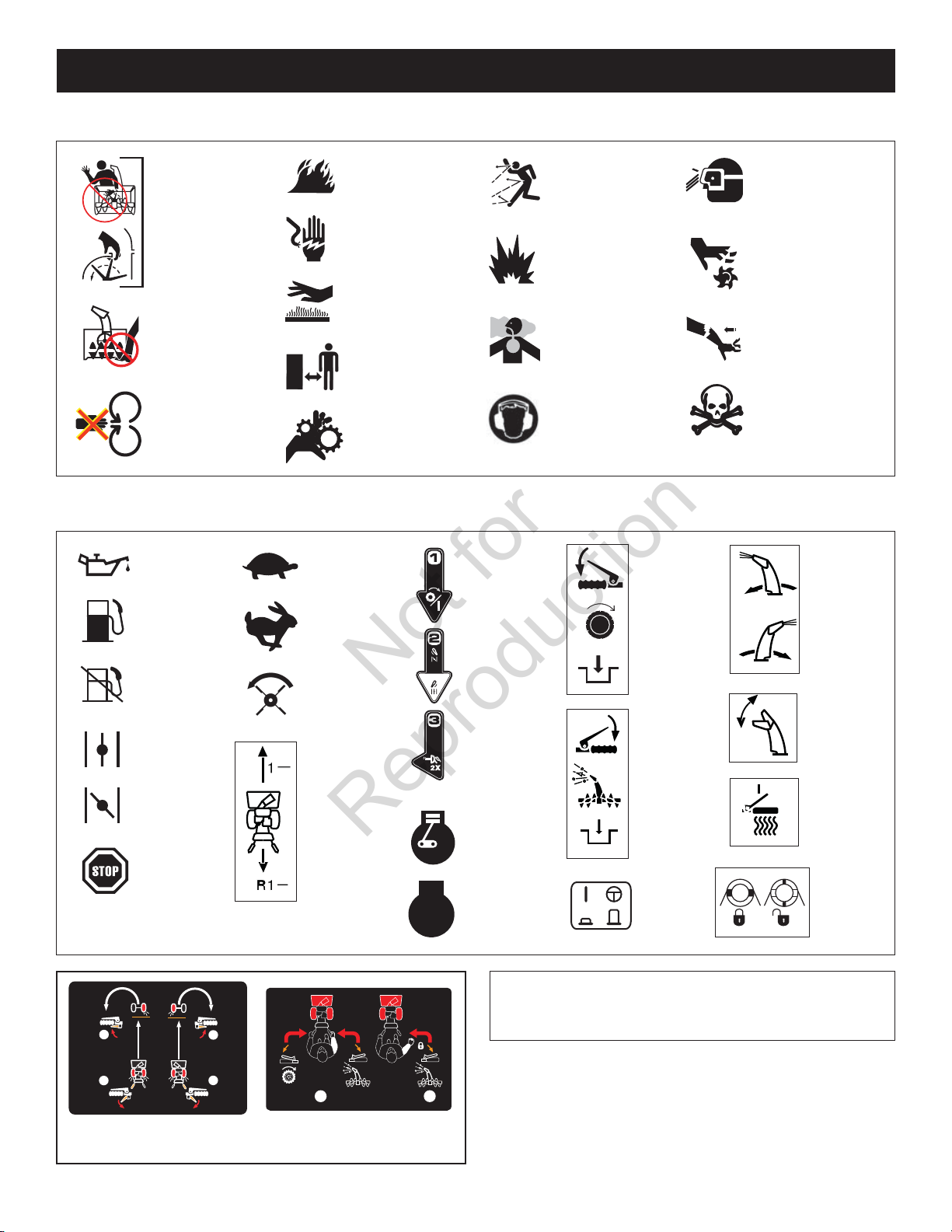
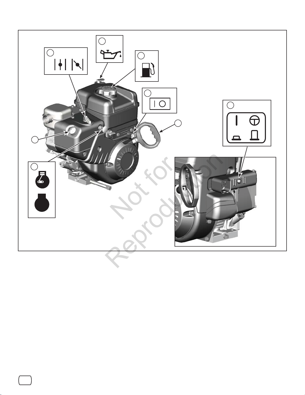
Hazard Symbols and Meanings
Not for
Reproduction
OPERATOR SAFETY
Rotating
Impeller
Rotating
Auger
Rotating
Parts
Control Symbols on Equipment
Oil
Fuel
Fuel
Shuto
Choke
O
Choke
On
Stop
Slow
Fast
Auger
Clutch
Forward
Neutral
Reverse
Fire
Shock
Hot
Surface
Safe
Distance
Rotating
Gears
STOP
Engine
On-O
ChokeRun
Engine
Primer
Engine
Run
Engine
Stop
Thrown
Objects
Explosion
Toxic
Fumes
Ear
Protection
Traction
Control
Auger
Control
Electric
Start
Eye
Protection
Moving
Parts
Kickback
Hazardous
Chemical
Discharge
Chute
Chute
De ector
Heated
Hand
Grips
Wheel
Lock
2
1
Traction Control
4
NOTE: Not all control symbols shown on this page will
appear on your snowthrower. See Features and Controls
2
section for the applicable symbols.
1
Easy-Turn™
1
Free-Hand™ Control
2
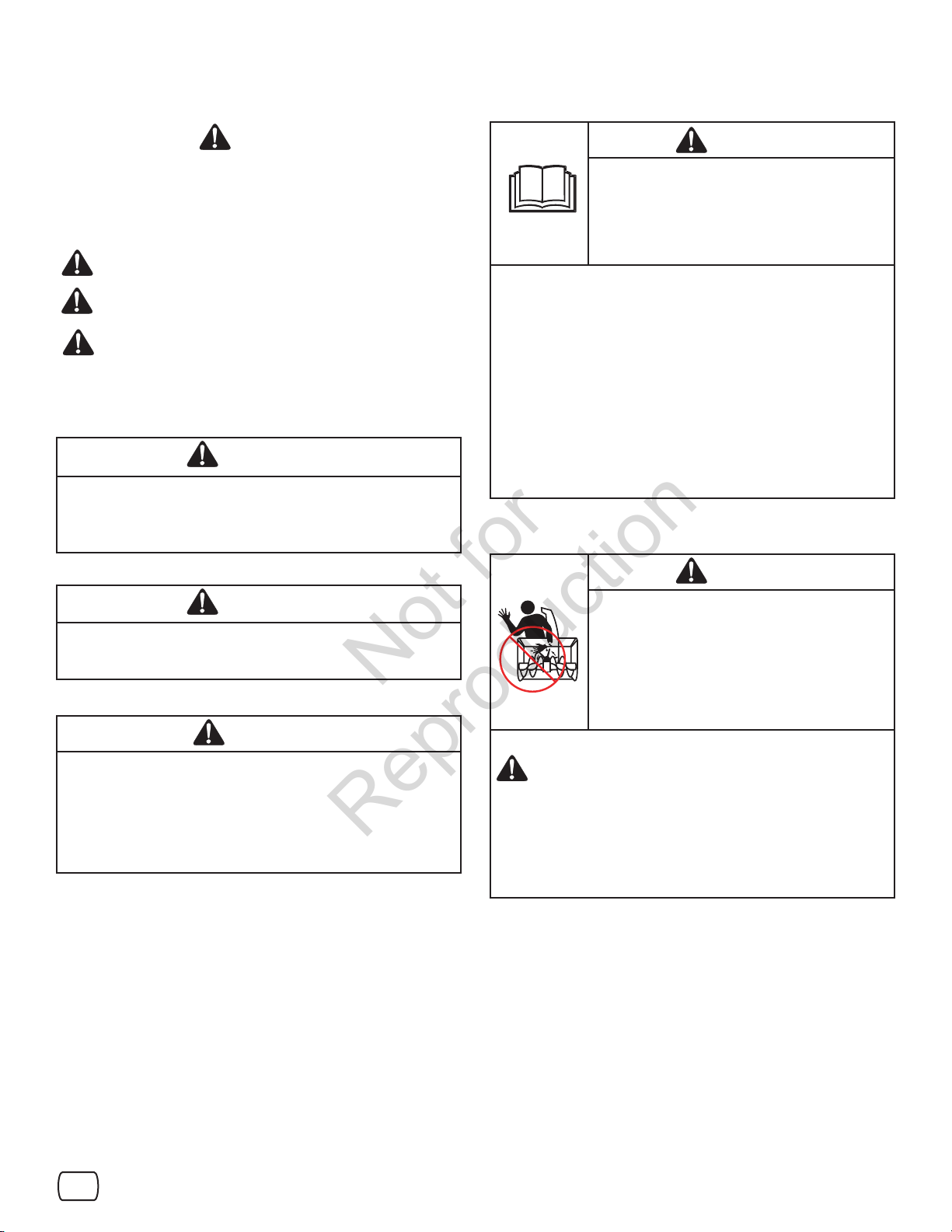
Safety Alert Symbol and Signal Words
Not for
Reproduction
Read the Manual
The safety alert symbol and signal word (DANGER,
WARNING, CAUTION, or NOTICE) is used to indicate the likelihood
and potential severity of personal injury and/or damage to the
product. In addition, a hazard symbol may be used to represent the
type of hazard.
DANGER indicates a hazard which, if not avoided, will result
in death or serious injury.
WARNING indicates a hazard which, if not avoided, could
result in death or serious injury.
CAUTION indicates a hazard which, if not avoided, could
result in minor or moderate injury.
NOTICE indicates a situation that could result in damage
to the product.
WARNING
Certain components in this product and its related accessories
contain chemicals known to the state of California to cause
cancer, birth defects, or other reproductive harm. Wash hands
after handling.
DANGER
Read, understand, and follow all the
instructions on the snowthrower and in the
operator’s manual before operating this unit.
Failure to observe the safet y instructions in
this manual will result in death or serious
injury.
• Be thoroughly familiar with the controls and the proper use of the
snow thrower.
• Make sure you are properly trained before operating the
snowthrower.
• Know how to stop the unit and disengage the controls quickly.
• Never allow anyone to operate the snowthrower without proper
instruction.
• Always follow the instructions in the operator’s manual, if the
snowthrower will be stored for an extende d period.
• Maintain or replace safety and instruction labels as necessary.
• Never attempt to make major repairs on the snowthrower
unless you have been properly trained. Improper servicing of
the snowthrower can result in hazardous operation, equipment
damage, and voiding of the product warranty.
Discharge Chute
DANGER
WARNING
The engine exhaust from this product contains chemicals
known to the State of California to cause cancer, birth defects,
or other reproductive harm.
DANGER
• Hand contact with the rotating impeller inside the discharge
chute is the most common cause of injury associated with
snowthrowers.
• This snowthrower is capable of amputating hands and
feet, and throwing objects. Read and observe all the safety
instructions in this manual. Failure to do so will result in
death or serious injury.
Discharge chute contains rotating impeller
to throw snow. Never clear or unclog the
discharge chute with your hands. Fingers can
quickly become caught in the impeller. Always
use a clean-out tool.
Failure to observe these safety instructions
will result in traumatic amputation or severe
laceration.
TO SAFELY CLEAR A CLOGGED DISCHARGE CHUTE
DANGER: Hand contact with the rotating impeller inside
the discharge chute is the most common cause of
injury associated with snow throwers. Never use your
hands to clean out the discharge chute.
FOLLOW THESE INSTRUCTIONS:
1. Shut OFF the engine.
2. Wait 10 seconds to be sure the impeller blades have stopped
rotating.
3. Always use a clean-out tool, not your hands.
en
5
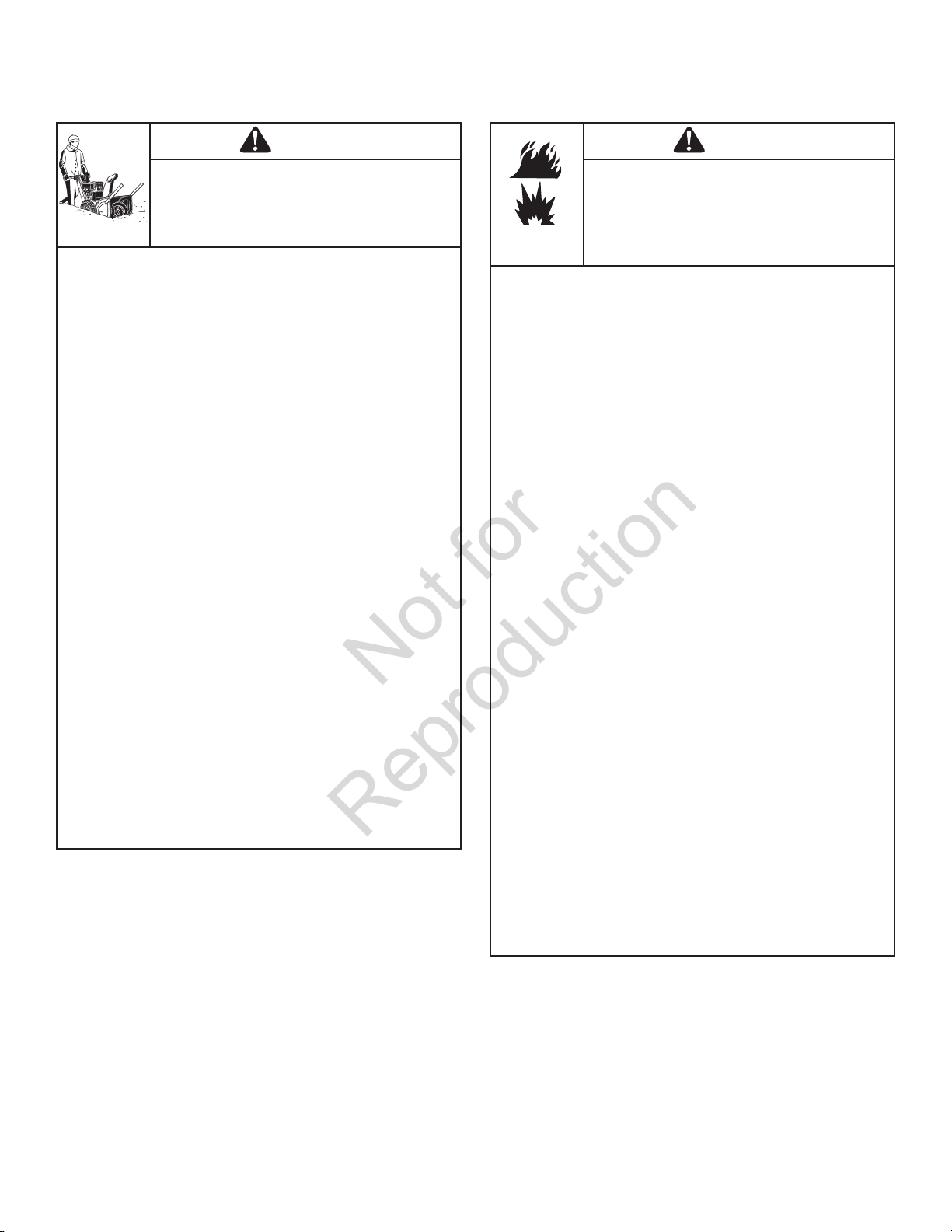
Operation and Equipment Safety
Not for
Reproduction
Fuel Handling
DANGER
This snowthrower is only as safe as the
operator. If it is misused, or not properly
maintained, it can be dangerous. Remember
you are responsible for your safety and that of
those around you.
• Keep the area of operation clear of all persons, particularly small
children and pets.
• Thoroughly inspect the area where the snowthrower will be used
and remove all doormats, sleds, boards, wires, and other foreign
objects.
• Do not operate the snowthrower without wearing adequate winter
clothing.
• Wear footwear that will improve footing on slippery surfaces.
• Use caution to avoid slipping or falling especially when operating
the snowthrower in reverse.
• Never operate the snowthrower without good visibility or light.
Always be sure of your footing, and keep a rm hold on the
handles.
• Do not clear snow across the face of slopes. Use extreme caution
when changing direction on slopes. Do not attempt to clear steep
slopes.
• Do not overload the machine capacity by attempting to clear
snow too quickly.
• Never operate the snowthrower at high transport speeds on
slippery surfaces. Look behind the snowthrower and use care
when operating in reverse.
• Do not use the snowthrower on surfaces above ground level such
as roofs of residences, garages, porches, or other such structures
or buildings.
• Operators should evaluate their ability to operate the snowthrower
safely enough to protect themselves and others from injury.
• The snowthrower is intended to remove snow only. Do not use
the snow thrower for any other purpose.
• Do not carry passengers.
• After striking a foreign object, shut OFF the engine, disconnect
the cord on electric motors, thoroughly inspect the snowthrower
for any damage, and repair the damage before restarting and
operating the snowthrower.
• If the snowthrower vibrates abnormally, shut OFF the engine.
Vibration is generally a warning of trouble. See an authorized
dealer if necessary for repairs.
• For models equipped with electric starting motors, disconnect the
power cord after the engine starts.
DANGER
Fuel and its vapors are extremely ammable
and explosive. Always handle fuel with extreme
care.
Failure to observe these safety instructions can
cause a re or explosion which will result in
severe burns or death.
WHEN ADDING FUEL
• Turn o engine and let cool at least 2 minutes before removing
the fuel cap and adding fuel.
• Fill fuel tank outdoors or in a well ventilated area.
• Do not over ll the fuel tank. To allow for the expansion of
gasoline, do not ll above the bottom of the fuel tank neck.
• Keep fuel away from sparks, open ames, pilot lights, heat, and
other ignition sources.
• Check fuel lines, cap, and ttings frequently for cracks or leaks.
Replace if necessary.
• Use an approved fuel container.
• If fuel spills, wait until it evaporates before starting engine.
WHEN STARTING ENGINE
• Ensure that spark plug, mu er, fuel cap, and air cleaner (if
equipped) are in place and secured.
• Do not crank the engine with the spark plug removed.
• If fuel is spilled, do not attempt to start the engine, but move the
snowthrower away from the area of the spill, and avoid creating
any source of ignition, until the fuel vapors have dissipated.
• Do not over-prime the engine. Follow the engine starting
instructions in this manual.
• If the engine oods, set choke (if equipped) to OPEN/RUN
position, move throttle (if equipped) to FAST position and crank
until engine starts.
WHEN OPERATING EQUIPMENT
• Do not tip the snowthrower at an angle which causes the fuel to
spill.
• Do not choke the carburetor to stop the engine.
• Never run the engine with the air cleaner assembly (if equipped)
or the air lter (if equipped) removed.
WHEN CHANGING OIL
• If you drain the oil from the top oil ll tube, the fuel tank must be
empty or fuel can leak out and result in a re or explosion.
WHEN TRANSPORTING EQUIPMENT
• Transport with fuel tank EMPTY, or with fuel shut-o valve OFF.
WHEN STORING GASOLINE OR EQUIPMENT WITH FUEL
IN TANK
• Store away from furnaces, stoves, water heaters, or other
appliances that have pilot light or other ignition source because
they can ignite fuel vapors.
6
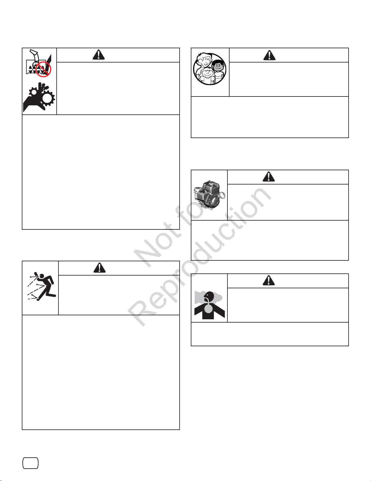
Moving Parts
Not for
Reproduction
Children
DANGER
Keep hands, feet, and clothing away from
rotating parts. Rotating parts can contact
or entangle hands, feet, hair, clothing, or
accessories.
Failure to observe these safety instructions
will result in traumatic amputation or severe
laceration.
• Whenever cleaning, repairing, or inspecting the snowthrower,
make sure the engine is OFF, spark plug wire is disconnected,
and all moving parts have stopped.
• Do not put hands or feet near or under rotating parts. Keep clear
of the discharge opening at all times.
• Never operate the snowthrower without proper guards, and other
safety devices in place and working.
• Never leave the snowthrower unattended while engine is running.
Always disengage the auger and traction controls, stop engine,
and remove keys.
• Keep all loose clothing away from the front of the snowthrower
and auger. Scarves, mittens, dangling drawstrings, loose clothes,
and pants can quickly become caught in the rotating device and
amputation will occur. Tie up long hair and remove jewelry.
• Run the machine a few minutes after discharging snow to prevent
freeze-up of the collector/impeller.
• Disengage power to the collector/impeller when snowthrower is
transported or not in use.
Thrown Objects
DANGER
Tragic accidents can occur if the operator
is not alert to the presence of children.
Children are often attracted to the unit and the
operating activity. Never assume that children
will remain where you last saw them.
• Keep children out of the area during operation. Children are often
attracted to the equipment. Be mindful of all persons present.
• Be alert and turn unit o if children enter the area.
• Never allow children to operate the unit.
• Use extra care when approaching blind corners, shrubs, trees, or
other objects that may obscure vision. Children may be present.
Engine Safety
DANGER
Safe operation of the snowthrower requires the
proper care and maintenance of the engine.
Failure to observe the safety instructions in this
manual will result in death or serious injury.
• Disengage all clutches and shift into neutral before starting the
engine.
• Let the engine adjust to outdoor temperatures before starting to
clear snow.
• Use a grounded three-wire plug-in for all snowthrowers equipped
with electric drive motors or electric starting motors.
DANGER
Objects can be picked up by auger and thrown
• Always wear safety glasses or eye shields during operation, and
while performing an adjustment or repair.
• Always be aware of the direction the snow is being thrown.
Nearby pedestrians, pets, or property may be harmed by objects
being thrown.
• Be aware of your environment while operating the snowthrower.
Don’t run over items such as gravel, doormats, newspapers, toys,
and rocks hidden under snow, as they can all be thrown from the
chute or jam in the auger.
• Use extreme caution when operating on or crossing gravel drives,
walks, or roads.
• Adjust the collector housing height to clear gravel or crushed rock
surface.
• Never operate the snowthrower near glass enclosures,
automobiles, window wells, drop-o s, and the like without proper
adjustment of the discharge chute angle.
• Familiarize yourself with the area in which you plan to operate the
snow thrower. Mark o boundaries of walkways and driveways.
from chute. Never discharge snow toward
bystanders or allow anyone in front of the
snowthrower. Failure to observe these safety
instructions will result in death or serious
injury.
DANGER
Engines give o carbon monoxide, an odorless,
colorless, poison gas.
Breathing carbon monoxide can cause nausea,
fainting, or death.
• Start and run engine outdoors.
• Do not run the engine in an enclosed area, even if doors or
windows are open.
en
7
Engine Safety (Continued)
Not for
Reproduction
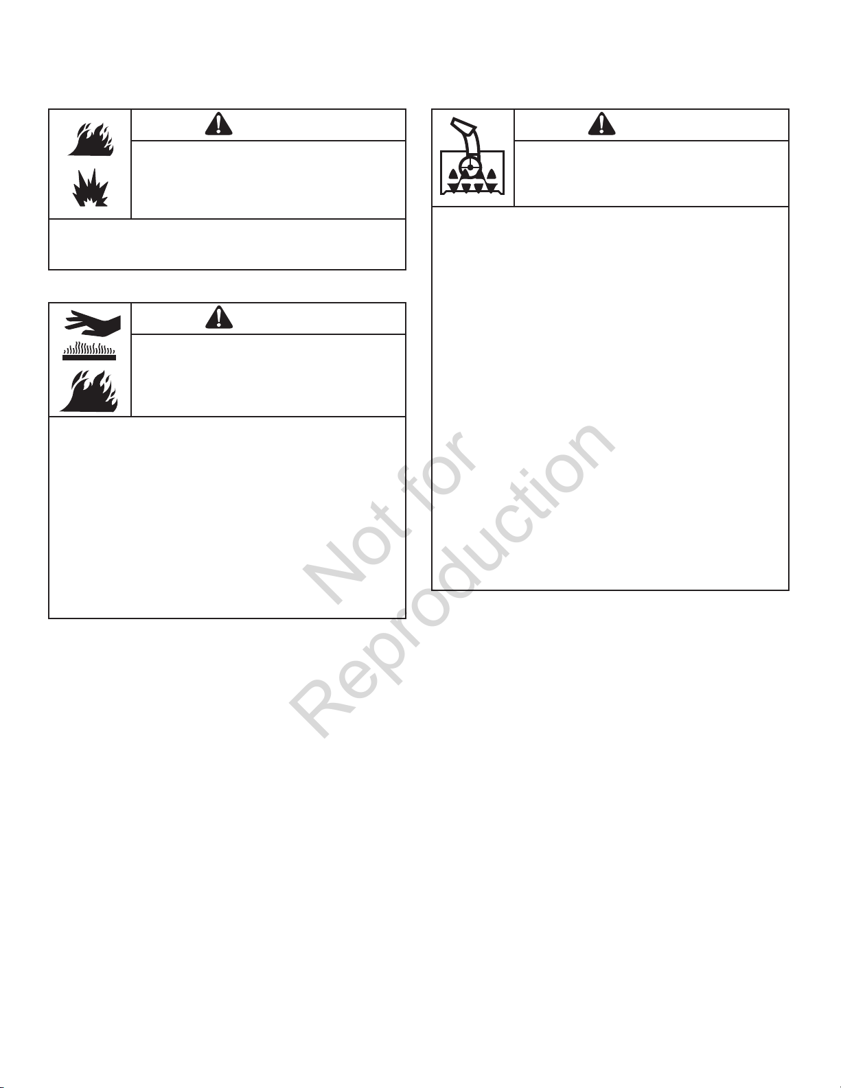
Maintenance and Storage
WARNING
Starting engine creates sparking.
Sparking can ignite nearby ammable gases.
Explosion and re could result.
• If there is natural or LP gas leakage in area, do not start engine.
• Do not use pressurized starting uids because vapors are
ammable.
WARNING
Running the engine produces heat. Engine
parts, especially mu er, become extremely hot.
Failure to observe these safety instructions
could result in severe thermal burns on contact.
• Never touch a hot engine or mu er. Allow mu er, engine
cylinder, and ns to cool before touching.
• Remove debris from mu er area and cylinder area.
• Install and maintain in working order a spark arrester before using
equipment on forest-covered, grass-covered, or brush-covered
unimproved land.
• It is a violation of California Public Resource Code, Section
4442, to use or operate the engine on any forest-covered,
brush-covered, or grass-covered land unless the exhaust
system is equipped with a spark arrester, as de ned in Section
4442, maintained in e ective working order. Other states or
federal jurisdictions may have similar laws. Contact the original
equipment manufacturer, retailer, or dealer to obtain a spark
arrester designed for the exhaust system installed on this engine.
WARNING
This snowthrower must be properly maintained
to ensure safe operation and performance.
Failure to observe the safety instructions in this
manual could result in death or serious injury.
• When performing any maintenance or repairs on the
snowthrower, shut OFF the engine, disconnect spark plug wire,
and keep the wire away from the plug to prevent someone from
accidently starting the engine.
• Check shear bolts and other hardware at frequent intervals for
proper tightness to be sure the snowthrower is in safe working
condition.
• Keep nuts and bolts tight and keep snowthrower in good
condition.
• Never tamper with safety devices. Check their proper operation
regularly and make necessary repairs if they are not functioning
properly.
• Components are subject to wear, damage, and deterioration.
Frequently check components and replace with recommended
parts, when necessary.
• Check control operation frequently. Adjust and service as
required.
• Use only factory authorized replacement parts, or equivalent,
when making repairs.
• Always comply with factory speci cations on all settings and
adjustments.
• Only authorized service locations should be utilized for major
service and repair requirements.
• Use only attachments and accessories approved by the factory
(such as wheel weights, counterweights, or cabs).
• Never attempt to make any adjustments while the engine is
running (except when speci cally recommended by the factory).
8
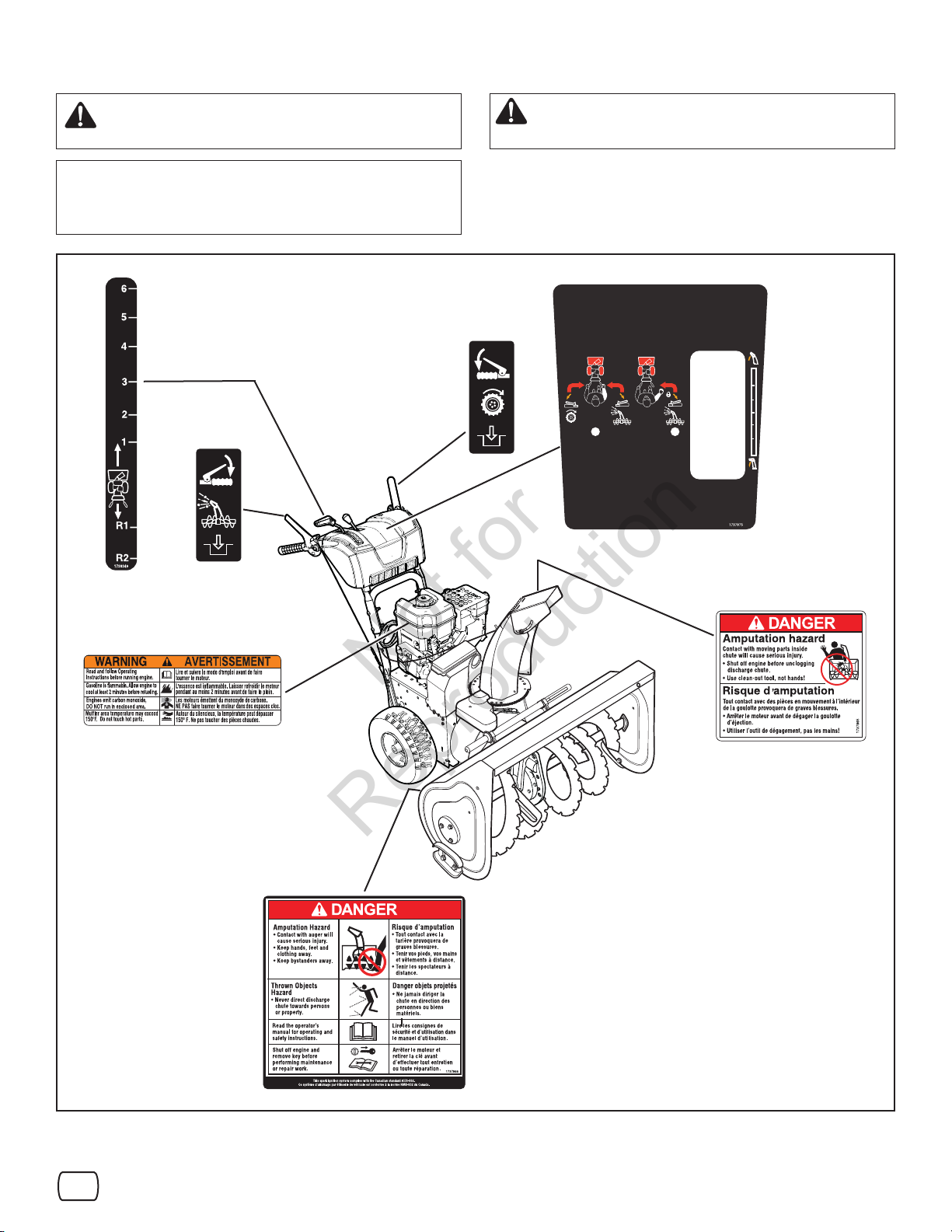
Look for this symbol to indicate important safety
Not for
Reproduction
precautions. This symbol indicates: “Attention!
Become Alert! Your Safety Is At Risk.”
Before operating your snowthrower, read the safety decals as
shown on your snowthrower. The cautions and warnings are
for your safety. To avoid a personal injury or damage to your
snowthrower, understand and follow all the safety decals.
Part No. 1738349
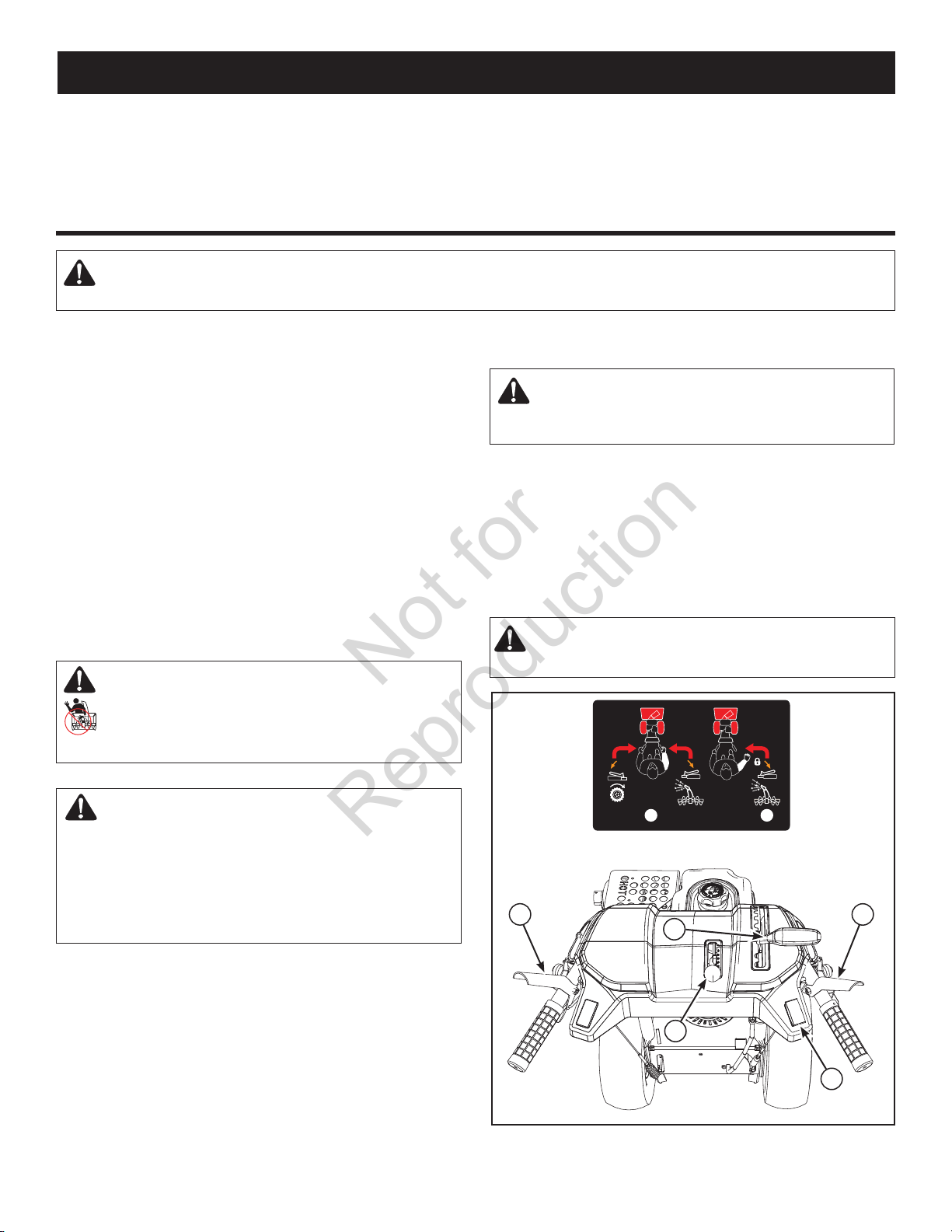
Shift Decal
Part No. 1753134
Traction Control Decal
WARNING: If any safety decals become worn or
damaged and cannot be read, order replacement
decals from your local dealer.
1753134
1
2
Part No. 1753133
Auger Control Decal
Part No. 278297
Engine Decal
1753133
Part No. 1737875
Main Dash Decal
Part No. 1737865
Chute Danger Decal
Part No. 1737866
Auger Danger Decal
Safety Decals Figure 1
en
9
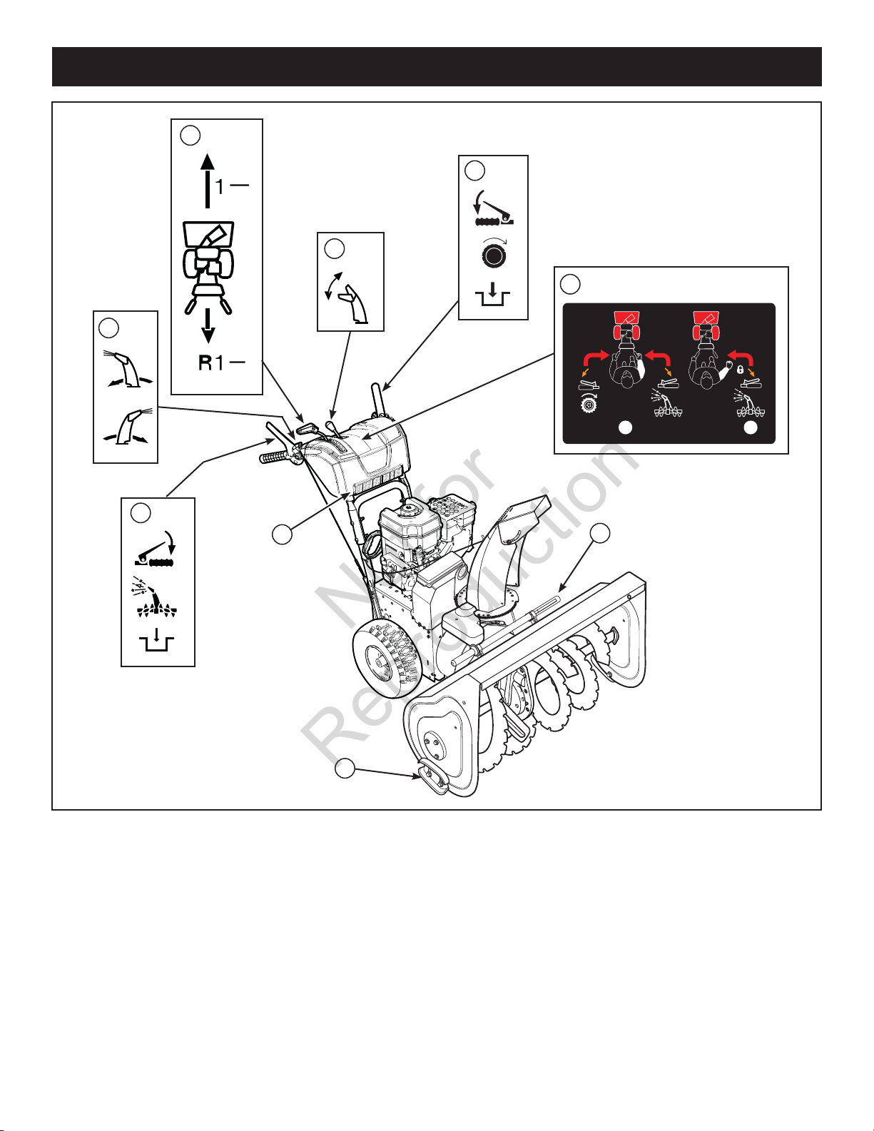
FEATURES AND CONTROLS
Not for
Reproduction
A
F
D
E
C
1
B
I
H
Snowthrower Controls Figure 2
G
2
SNOWTHROWER CONTROLS
A. Speed Select Lever — Allows the operator to use one of six
(6) forward and two (2) reverse speeds (see Figure 2). To shift,
move speed select lever to desired position.
NOTICE: Do not move speed select lever while Traction
Control is engaged. This may result in severe damage to
the drive system.
B. Auger Control Lever — Used to engage and disengage
the auger and impeller. To engage push down, to disengage
release.
10
C. Chute Rotation Switch — Used to rotate the discharge chute
to the left or right.
D. De ector Control Lever — Used to control the angle of the
chute de ector (up or down).
E. Free-Hand™ Control — After engaging the traction control
(left hand) and auger control (right hand), allows the operator to
release the auger control lever to use the other controls.
F. Traction Control Lever — Used to propel snowthrower
forward or reverse. Push down to engage, release to disengage.
H
Not for
Reproduction
A
C
D
G
F
B
E
STOP
Engine Controls Figure 3
SNOWTHROWER CONTROLS (Continued)
G. Clean-Out Tool — Used to remove snow and debris from the
discharge chute and the auger housing.
H. Skid Shoe — Used to adjust the ground clearance of the auger
housing.
I. Headlight — Used to operate the snowthrower in poor lighting
conditions.
ENGINE CONTROLS
A. Choke Control Knob — Used to start a cold engine (see
Figure 3).
B. Electric Start Button — Used to start the engine using the
electric starter.
C. Primer Button — Used to inject fuel directly into the carburetor
manifold to ensure fast starts in cool weather.
D. Safety Key — Must be inserted to start engine. Pull out to stop.
Do not turn safety key.
E. Starter Cord Handle — Used to start the engine manually.
F. ON/OFF Switch — Used to start and stop the engine.
G. Fuel Tank and Cap — Fill the fuel tank to approximately
1-1/2 in. (38 mm) below the top of the neck to allow for fuel
expansion.
H . Oil Fill Cap (Extended Dipstick)
en
11
OPERATION
Not for
Reproduction
BEFORE OPERATING SNOWTHROWER
• Check the fasteners. Make sure all fasteners are tight.
• On electric start models, the unit was shipped with the
starter cord plugged into the engine. Before operating,
unplug the starter cord from the engine.
WARNING: The operation of any snowthrower can result in foreign objects being thrown into the eyes, which can result in
severe eye damage. Always wear safety glasses or eye shields before beginning snowthrower operation. We recommend
standard safety glasses or Wide Vision Safety Mask over spectacles.
SNOWTHROWER SAFETY TESTS
Test 1 - Auger/Impeller
• Release auger control (right-hand).
• Auger/impeller stops in less than 5 seconds.
Test 2 - Traction Drive
• Release traction control (left-hand).
• Snowthrower forward/reverse motion stops.
Test 3 - Free-Hand Control (if equipped)
• Engage auger control and traction control.
• Release auger control immediately followed by the traction
control (a) stops auger/impeller in less than 5 seconds, and (b)
stops forward/reverse motion of snowthrower.
DANGER: The discharge chute contains a rotating
impeller to throw snow. Never clear or unclog the
discharge chute with your hands. Fingers can quickly
become caught and traumatic amputation or severe
laceration will result. Always use a clean-out tool to
clear or unclog the discharge chute.
NOTE: This snowthrower was shipped WITH OIL in the
engine. See Check the Oil (Before Starting Engine)
instructions in this section before starting engine.
OPERATE THE SNOWTHROWER
CAUTION: Operation with a Snow Cab. Wind may
blow exhaust gasses back towards the operator. If
you notice the smell of exhaust, change direction of
operation.
NOTICE: Do not throw snow toward a building as hidden
objects could be thrown with su cient force to cause
damage.
1. Start the engine. See Start the Engine in this section.
2. Press the chute rotation switch (A, Figure 4) to the UP/DOWN
position to rotate the discharge chute left or right. See Dis-
charge Chute and De ector in this section.
CAUTION: Before operating, make sure the area in
front of the snowthrower is clear of bystanders or
obstacles.
WARNING:
• Hand contact with the rotating impeller inside
the discharge chute is the most common cause of
injury associated with snowthrowers.
• This snowthrower is capable of amputating hands
and feet, and throwing objects. Read and observe
all the safety instructions in this manual. Failure to
do so will result in death or serious injury.
12
1
Free-Hand
D
Control Levers Figure 4
TM
E
B
2
Control
C
A
3. Push the de ector control lever (B) forward or pull back to
Not for
Reproduction
control the angle of the chute de ector. See Discharge
Chute and De ector in this section.
4. Fully press and hold the auger control lever (C) to engage
auger rotation. Releasing the auger control lever will
disengage the auger - unless the Free-Hand™ control has
been activated.
5. Fully press and hold the traction and Free-Hand™ control
lever (D) to engage the traction drive and begin moving the
snowthrower. To disengage the traction drive, completely
release the lever.
6. When BOTH levers are pressed, the Free-Hand™ control is
activated. This allows you to release the auger control lever to
use the other controls. The auger will continue to rotate until
the traction/Free-Hand™ control lever is released.
NOTE: Always release the traction control lever before
moving the speed select lever.
7. Use the speed select lever (E) to select the forward drive
speed. Set the speed select lever to one of the following
positions as determined by snow conditions:
1-2 Wet, Heavy, Slushy, Extra Deep
3 Moderate
4-5 Very Light
6 Transport
NOTE: When clearing wet, heavy, snow, it is recommended
that the ground speed of the unit be reduced, full throttle be
maintained and no attempt be made to clear the full width
of the unit.
8. To stop moving forward, release the traction control lever (D).
9. To move the snowthrower backwards, move the speed select
lever into either rst or second reverse position and engage
the traction control lever.
STOP THE SNOWTHROWER
1. Release the auger control lever (C, Figure 4).
2. Release the traction control lever (D).
3. Push the ON/OFF switch (A, Figure 12) to the OFF position
and pull out the safety key (B).
WARNING: Read Operator’s Manual before operating
machine. This machine can be dangerous if used
carelessly.
• Never operate the snowthrower without all guards, covers,
and shields in place.
• Never direct discharge towards windows or allow
bystanders near machine while engine is running.
• Stop the engine whenever leaving the operating position.
• Disconnect spark plug before unclogging the impeller
housing or the discharge chute and before making repairs
or adjustments.
• When leaving the machine, remove the safety key. To
reduce the risk of re, keep the machine clean and free
from spilled gas, oil, and debris.
WARNING: Never run engine indoors or in an
enclosed, poorly ventilated area. Engine exhaust
contains CARBON MONOXIDE, an ODORLESS and
DEADLY GAS.
• Keep hands, feet, hair, and loose clothing away from any
moving parts on engine and snowthrower.
• Temperature of mu er and nearby areas can exceed
150°F (66°C). Avoid these areas.
• DO NOT allow children or young teenagers to operate or
be near snowthrower while it is operating.
en
13
TRACTION LOCK PIN
Not for
Reproduction
The right traction wheel can be completely released using the
locking pin (A, Figure 5). This allows the unit to be easily moved
with the engine o .
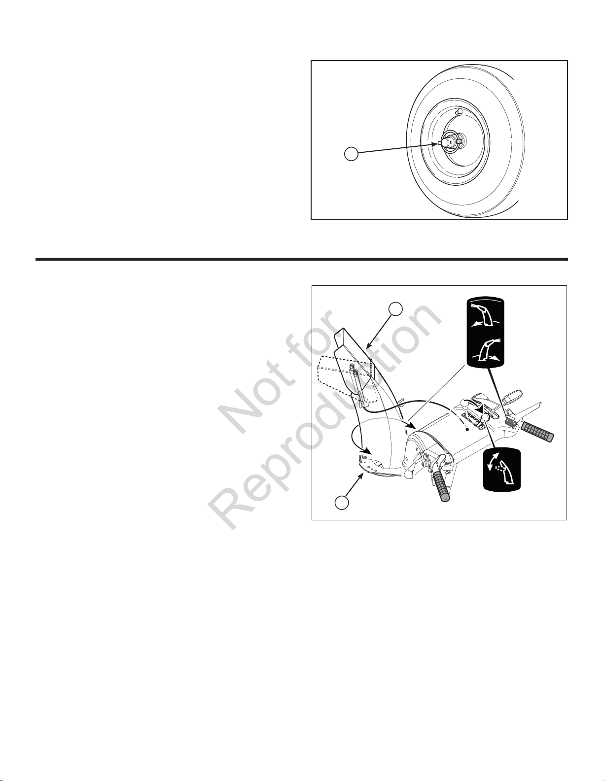
DISCHARGE CHUTE AND DEFLECTOR
Discharge Chute Rotation (Left/Right)
1. Press the chute rotation switch to the UP position and hold to
rotate the chute to the left (A, Figure 6).
2. After the desired position is obtained, release the switch to
the CENTER position to turn o .
3. Press the switch to the DOWN position and hold to rotate the
chute to the right.
A
Traction Lock Pin Figure 5
B
Chute De ector (Up/ Down)
1. Push the de ector control lever FORWARD to provide a
higher stream and greater distance (B, Figure 6).
2. Pull the de ector control lever BACK to provide a lower
stream and less distance.
A
Discharge Chute and De ector Figure 6
14
CHECK THE OIL (BEFORE STARTING ENGINE)
Not for
Reproduction
NOTE: The engine was shipped from the factory lled with
oil. Check the level of the oil. Add oil as needed.
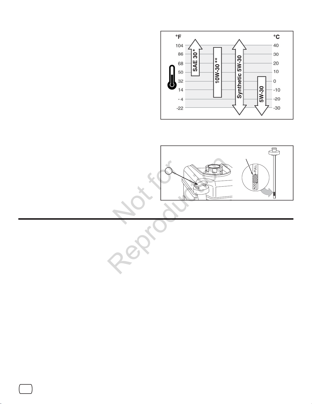
1. Make sure the unit is level. Use a high quality detergent oil
classi ed “For Service SG, SH, SJ, SL, or higher”.
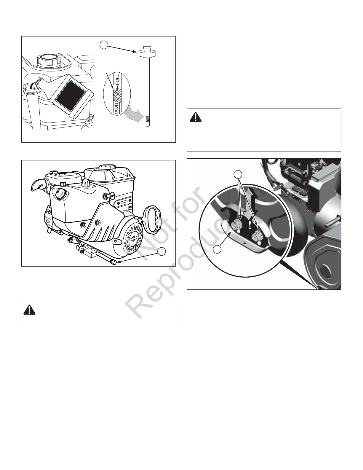
2. Remove the oil ll cap/dipstick (A, Figure 7) and wipe with a
clean cloth.
3. Insert the oil ll cap/dipstick and turn clockwise to tighten.
4. Remove the oil ll cap/dipstick and check the oil.
NOTE: Do not check the level of the oil while the engine
runs.
5. If necessary, add oil until the oil reaches the FULL mark on the
oil ll cap/dipstick. Do not add too much oil.
6. Tighten the oil ll cap/dipstick securely each time you check
the oil level.
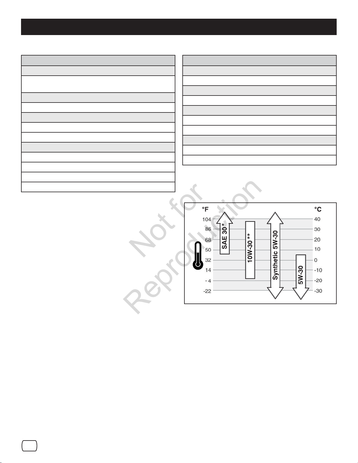
NOTE: Synthetic 5W30 motor oil is acceptable for all
temperatures. DO NOT mix oil with gasoline. See Chart for
oil recommendations.
* Below 40°F (4°C) the use of SAE 30 will result in hard starting.
** Above 80°F (27°C) the use of 10W-30 may cause increased oil
consumption. Check oil level more frequently.
FULL
FULL
A
FUEL RECOMMENDATIONS
Fuel must meet these requirements:
• Clean, fresh, unleaded gasoline.
• A minimum of 87 octane/87 AKI (91 RON). High altitude use,
see below.
• Gasoline with up to 10% ethanol (gasohol) or up to 15% MTBE
(methyl tertiary butyl ether) is acceptable.
NOTICE: Do not use unapproved gasolines, such as E85.
Do not mix oil in gasoline or modify the engine to run on
alternate fuels. This will damage the engine components
and void the engine warranty.
To protect the fuel system from gum formation, mix a fuel stabilizer
into the fuel. All fuel is not the same. If starting or performance
problems occur, change fuel providers or change brands. This
engine is certi ed to operate on gasoline. The emissions control
system for this engine is EM (Engine Modi cations).
Checking the Oil Figure 7
High Altitude
At altitudes over 5,000 feet (1524 meters), a minimum 85 octane/85
AKI (89 RON) gasoline is acceptable. To remain emissions
compliant, high altitude adjustment is required. Operation without
this adjustment will cause decreased performance, increased fuel
consumption, and increased emissions. See a Briggs & Stratton
Authorized Dealer for high altitude adjustment information.
Operation of the engine at altitudes below 2,500 feet (762 meters)
with the high altitude kit is not recommended.
en
15
ADDING FUEL
Not for
Reproduction
WARNING:
Fuel and its vapors are extremely ammable and
explosive.
Fire or explosion can cause severe burns or death.
When Adding Fuel
• Turn engine o and let engine cool at least 2 minutes before
removing the fuel cap.
• Fill fuel tank outdoors or in well-ventilated area.
• Do not over ll fuel tank. To allow for expansion of the fuel, do
not ll above the bottom of the fuel tank neck.
• Keep fuel away from sparks, open ames, pilot lights, heat,
and other ignition sources.
• Check fuel lines, tank, cap, and ttings frequently for cracks or
leaks. Replace if necessary.
• If fuel spills, wait until it evaporates before starting engine.
START THE ENGINE
Be sure that engine oil is at FULL mark on the oil ll cap/dipstick.
The snowthrower engine is equipped with an AC electric starter
and recoil starter. Before starting the engine, be certain that you
have read the following information.
If engine oods, set the choke to the OPEN/RUN position and
crank until the engine starts.
1. Clean the fuel cap area of dirt and debris. Remove the fuel
cap (G, Figure 3).
2. Fill the fuel tank with fuel. To allow for expansion of the fuel,
do not ll above the bottom of the fuel tank neck.
3. Reinstall the fuel cap.
Start the engine as follows:
1. Check the oil level. See the Check/Add Oil section in the
Engine Manual.
2. Make sure equipment drive controls are disengaged.
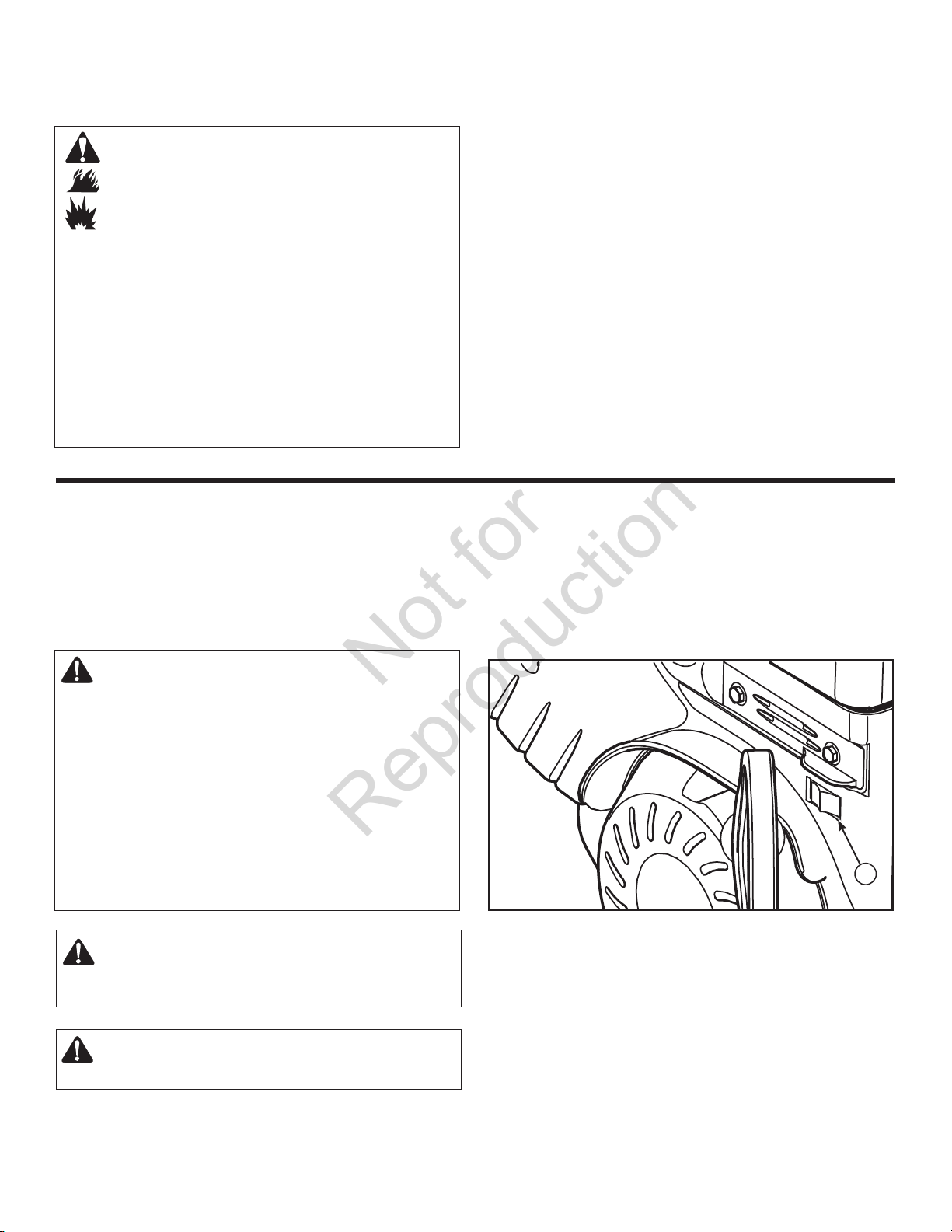
3. Push the ON /OFF switch (A, Figure 8) to the ON position.
WARNING: The electric starter is equipped with a threewire power cord and plug designed to operate on AC
household current. The power cord must be properly
grounded at all times to avoid the possibility of electric
shock which can cause injury to the operator. Follow all
instructions carefully as set forth:
Make sure your house has a three-wire grounded
system.
If you are not sure, ask a licensed electrician. If your
house does not have a three-wire grounded system, do
not use this electric starter under any condition.
If your house has a three-wire grounded system but
a three-hole receptacle is not available to connect the
electric starter, have a three-hole receptacle installed by
a licensed electrician.
WARNING: To connect power cord, always connect the
power cord rst to the switch box located on the engine
and then plug the other end into a three-hole grounded
receptacle.
WARNING: To disconnect the power cord, always
unplug the end connected to the three-hole grounded
receptacle rst.
A
Starting Engine Figure 8
16
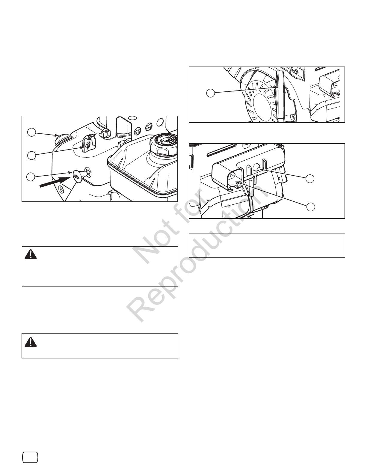
4. Insert the safety key (A, Figure 9) into the safety key slot and
Not for
Reproduction
push fully in to the RUN position.
5. Turn the choke knob (B) fully clockwise if engine is cold.
NOTE: Do not use the choke to start a warm engine.
6. Push the primer button (C) two times.
NOTE: Do not use the primer to start a warm engine.
NOTE: Ensure that electric extension cord is removed from
the power receptacle.
9. Electric Start: Depress the starter push button (A, Figure
11). After you start the engine, rst disconnect the extension
cord from the wall receptacle and then from the power cord
receptacle (B).
A
C
B
A
Inserting Safety Key Figure 9
7. Rewind Start: Firmly hold the starter cord handle (A, Figure
10). Pull the starter cord handle slowly until resistance is felt,
then pull rapidly.
WARNING: Rapid retraction of the starter cord
(kickback) will pull your hand and arm toward the
engine faster than you can let go. Broken bones,
fractures, bruises, or sprains could result. When
starting engine, pull the starter cord slowly until
resistance is felt and then pull rapidly to avoid kickback.
NOTE: If the engine does not start after three attempts, see the
Troubleshooting section in the Engine Manual
8. Electric Start: First connect the extension cord to the power
cord receptacle and then into a wall receptacle. If additional
extension cord is required, make sure it is three-wire.
.
Starting with Cord Handle Figure 10
A
B
Starting with Electric Start Figure 11
IMPORTANT: To extend the life of the starter, use short starting
cycles ( ve seconds maximum). Wait one minute between
starting cycles.
NOTE: If the engine does not start after three attempts, see the
Troubleshooting section in the Engine Manual.
WARNING: If the extension cord is damaged, it must be
replaced by the manufacturer (or its service agent) or a
similarly quali ed person to avoid a hazard.
en
17
STOP THE ENGINE
Not for
Reproduction
Before stopping the engine, idle for a few minutes to help dry o
any moisture on the engine.
WARNING: Gasoline and vapors are extremely
ammable and explosive. Fire or explosion can cause
severe burns or death. DO NOT choke the carburetor to
stop the engine.
1. Push the ON/OFF switch (A, Figure 12) to the OFF position.
2. Remove the safety key (B). Keep the safety key out of the
reach of children.
NOTE: Do not lose the safety key. Keep the safety key in
a safe place. The engine will not start without the safety/
ignition key.
B
A
Stopping Engine Figure 12
CLEAR A CLOGGED DISCHARGE CHUTE
DANGER: Hand contact with the rotating impeller inside
the discharge chute is the most common cause of injury
associated with snowthrowers. Never clear or unclog
discharge chute with your hands, or while engine
is running. Fingers can quickly become caught and
traumatic amputation or severe laceration can result.
• SHUT OFF THE ENGINE!
• Wait 10 seconds to be sure that the impeller blades have
stopped rotating.
• Always use a clean-out tool, not your hands.
A clean-out tool (A, Figure 13) is attached to either the handle or
the top of the auger housing. Use the clean-out tool to remove
snow from the auger housing.
A
OPERATING TIPS
1. Most e cient snowthrowing is accomplished when snow is
removed immediately after it falls.
2. For complete snow removal, slightly overlap each swath
previously taken.
3. Snow should be discharged downwind whenever possible.
4. For normal usage, set the skids 1/8 inch (3 mm) below the
scraper bar. For extremely hard-packed snow surfaces, the
skids may be adjusted upward to ensure cleaning e ciency.
5. On gravel or crushed rock surfaces, the skids should be set at
1-1/4 inch (32 mm) below the scraper bar (see Adjust Skid
Height in the Maintenance section of this manual). Rocks
and gravel must not be picked up and thrown by the machine.
6. After the snowthrowing job has been completed, allow
the engine to idle for a few minutes, to melt snow and ice
accumulated on the engine.
7. Clean the snowthrower thoroughly after each use.
8. Remove ice and snow accumulation and all debris from
the entire snowthrower, and ush with water (if possible) to
remove all salt or other chemicals. Wipe snowthrower dry.
9. Before starting snowthrower, always inspect augers and
impeller for ice accumulation and/or debris, which could result
in snowthrower damage.
10. Check oil level before every start. Make sure the oil is at the
FULL mark on the oil ll cap/dipstick.
Clean-Out Tool Figure 13
18
MAINTENANCE CHART
Not for
Reproduction
MAINTENANCE
SNOWTHROWER
After Each Use
Remove the snow and slush o snowthrower to prevent
freezing of controls
Every 8 Hours or Daily
Perform snowthrower safety tests
Every 25 Hours or Annually *
Check tire pressure
Check snowthrower for loose hardware
See Dealer Annually to
Lubricate control levers and linkages
Lubricate de ector hinge
Lubricate de ector motor (if equipped)
Lubricate chute rotation gear (if equipped)
EMISSIONS CONTROL STATEMENT
Maintenance, replacement, or repair of the emissions control
devices and systems may be performed by any non-road engine
repair establishment or individual. However, to obtain “no charge”
emissions control service, the work must be performed by a factory
authorized dealer. See the Emissions Warranty in the Engine
Manual.
ENGINE
First 5 Hours
Change engine oil
Every 8 Hours or Daily
Check engine oil level
Every 50 Hours or Annually *
Change engine oil
Check mu er and mu er guard.
See Dealer Annually to
Replace spark plug
Check valve clearance
* Not required unless there are problems with engine
performance.
ENGINE MAINTENANCE
Check Crankcase Oil Level - Before starting engine and after
each 8 hours of continuous use. Add the recommended motor oil
as required.
NOTE: Over lling the engine can a ect performance.
Tighten the oil ll cap securely to prevent leakage.
Change Oil - Every 50 hours of operation or at least once a year,
even if the snowthrower is not used for fty hours. Use a clean,
high quality detergent oil. Fill the crankcase to FULL line on dipstick
(A, Figure 14). Be sure original container is marked: A.P.I. service
“SG” or higher. Do not use SAE10W40 oil (as it may not provide
proper lubrication). See Chart for oil recommendations.
Drain Oil - Position snowthrower so that the oil drain plug (A,
Figure 15) is lowest point on engine. When the engine is warm,
remove oil drain plug and oil ll cap and drain oil into a suitable
container.
Replace oil drain plug and tighten securely. Re ll crankcase with
the recommended motor oil.
* Below 40°F (4°C) the use of SAE 30 will result in hard starting.
** Above 80°F (27°C) the use of 10W-30 may cause increased oil
consumption. Check oil level more frequently.
en
19
A
Not for
Reproduction
Full
Check Crankcase Oil Level Figure 14
To adjust skids, proceed as follows:
1. Place a block (equal to height from ground desired) under
scraper bar near but not under skid.
2. Loosen skid mounting nuts (A, Figure 16) and push the skid
down (B) until it touches the ground. Retighten mounting nuts.
3. Set skid on other side at same height.
NOTE: Make sure that snowthrower is set at same height on
both sides.
WARNING: Be certain to maintain proper ground
clearance for your particular area to be cleared.
Objects such as gravel, rocks, or other debris, if
struck by the impeller, may be thrown with su cient
force to cause personal injury, property damage, or
damage to the snowthrower.
A
A
Oil Drain Plug Figure 15
ADJUST SKID HEIGHT
WARNING: Always turn unit o , remove ignition key,
and disconnect the spark plug wire before making any
repairs or adjustments.
This snowthrower is equipped with two height adjust skids, secured
to the outside of the auger housing. These elevate the front of the
snowthrower.
When removing snow from a hard surface area such as a paved
driveway or walk, adjust the skids up to bring the front of the
snowthrower down.
When removing snow from rock or uneven construction, raise the
front of the snowthrower by moving the skids down. This will help
to prevent rocks and other debris from being picked up and thrown
by the augers.
B
Adjusting Skid Height Figure 16
20
AUGER CONTROL CABLE ADJUSTMENT
Not for
Reproduction
WARNING: Do not over-tighten, as this may lift the
lever and cause the auger drive to be engaged
without depressing the auger drive control.
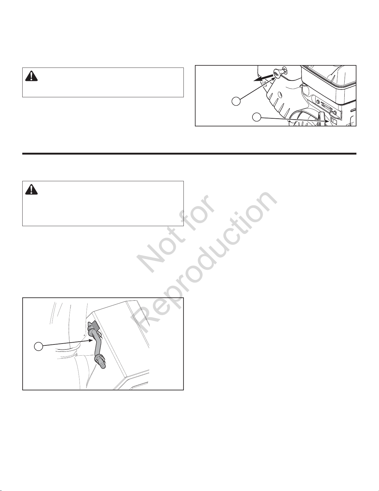
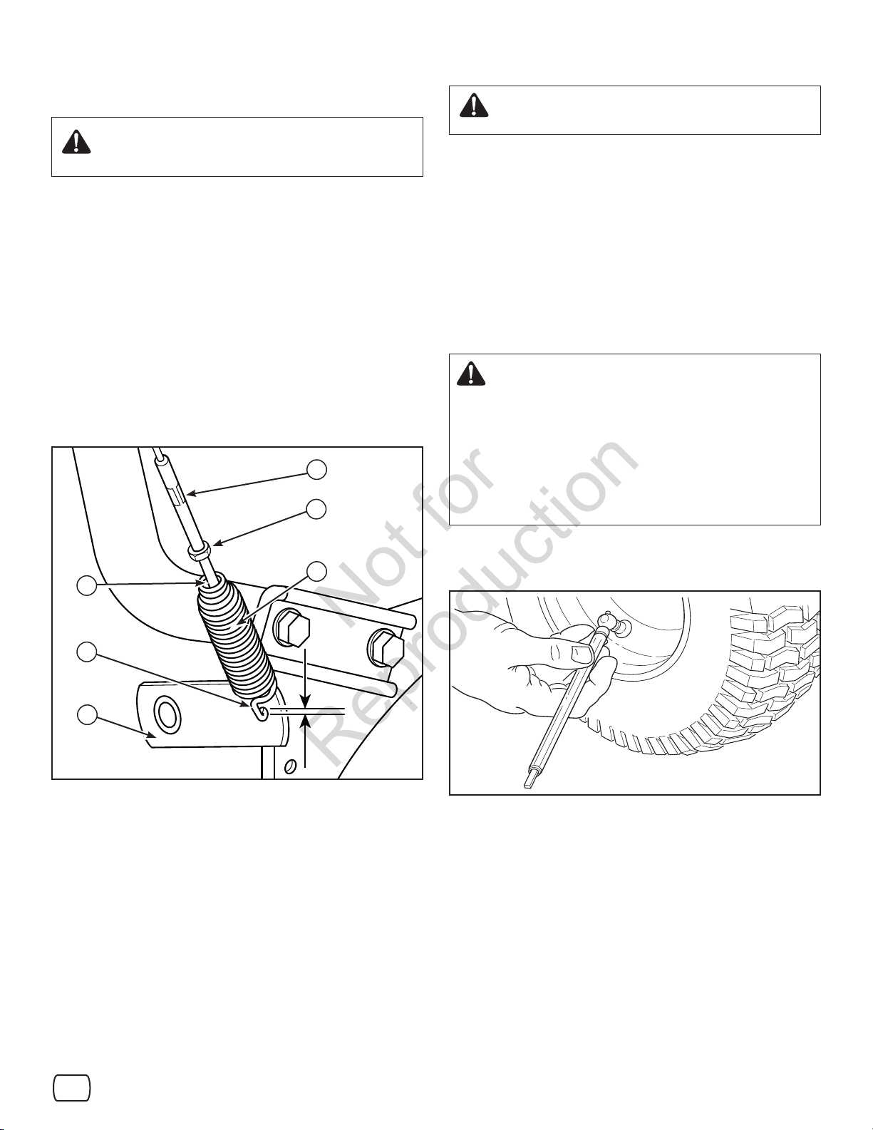
1. With the auger control lever released, the hook (A, Figure 17)
should barely touch the lever (B) without raising it. There can
be a maximum of 1/32 in. (0.8 mm) clearance.
2. To adjust, loosen the nut (C) by holding the adjusting ats (D)
and turning the nut. Then, turn the adjusting ats and hold
the adjustment screw (E). The adjustment screw is a phillips
screw and the head can be held or turned by inserting a
screwdriver through the spring (F).
3. Hold the adjusting ats and tighten the nut.
4. Start the engine and check the auger. The auger must not be
engaged unless the auger control lever is depressed.
5. With the engine running, fully depress the auger drive control
lever. The auger should engage and run normally.
D
C
WARNING: The auger must stop within 5 seconds. If it
does not, contact Sears Service.
6. Release the auger control lever.
7. If the auger does not operate properly, stop the engine and
recheck the auger control cable adjustment.
8. If the drive linkage is properly adjusted, the tension of the
auger drive belt may require an adjustment. See an authorized
dealer.
CHECK THE TIRES
Check tires for damage. Check the air pressure in the tires with an
accurate gauge (see Figure 18).
CAUTION: Avoid Injury! Explosive separation of tire
and rim parts is possible when they are serviced
incorrectly.
• Do not attempt to mount a tire without the proper equipment
and experience to perform the job.
• Do not in ate the tires above the recommended pressure.
• Do not weld or heat a wheel and tire assembly. Heat can
cause an increase in air pressure resulting in an explosion.
Welding can structurally weaken or deform the wheel.
• Do not stand in front or over the tire assembly when in ating.
Use appropriate tool that allows you to stand to one side.
E
A
B
Adjusting Auger Control Cable Figure 17
F
1/32”
(0.8mm)
NOTICE: Check side of tire for maximum tire pressure. DO NOT
exceed maximum.
Checking Tire Air Pressure Figure 18
en
21
AUGER SHEAR PIN REPLACEMENT
Not for
Reproduction
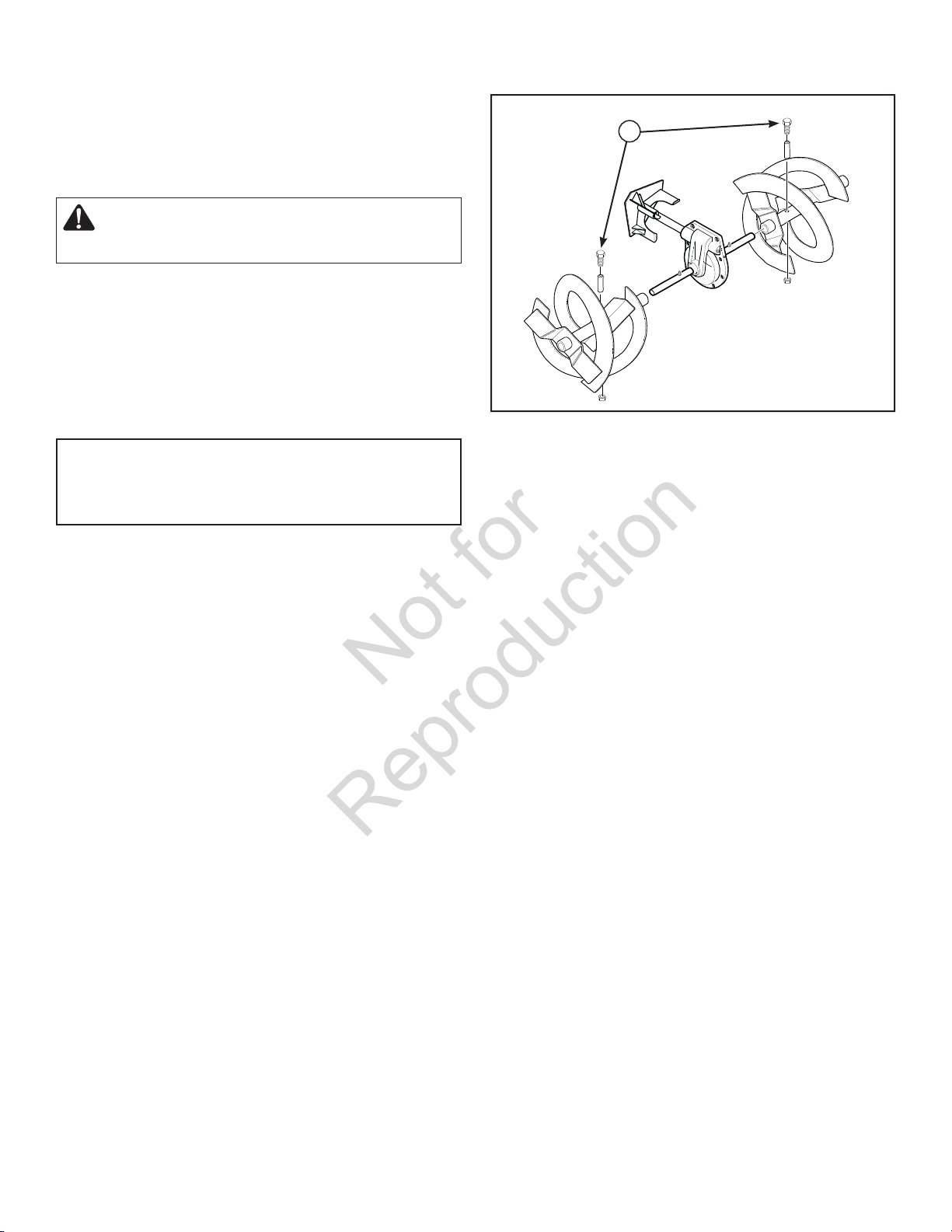
The augers are secured to the auger shaft with special shear pins
that are designed to break if an object becomes lodged in the
auger housing. Use of a harder grade shear pin will reduce the
protection provided by the shear pin.
WARNING: Do not go near the discharge chute or
auger when the engine is running. Do not run the
engine if any cover or guard is removed.
Under most circumstances, if the auger strikes an object which
could cause damage to the unit, the shear pin will break. This protects the gear box and other parts from damage.
The shear pins (A, Figure 19) are located on the auger shaft. Replace a broken shear pin as follows.
1. Tap out the broken shear pin with a pin punch.
2. Install a new shear pin and cotter pin. Bend the ends of the
cotter pin down.
IMPORTANT: Do not replace shear pins with anything
other than the correct grade replacement shear pin. Use
of bolts, screws, or harder grade shear pins can result in
equipment damage.
A
Replacing Broken Shear Pin Figure 19
22
STORAGE
Not for
Reproduction
WARNING: Never store the engine, with fuel in the
tank, indoors or in a poor ventilated enclosure where
fuel fumes could reach an open ame, spark or pilot
light as on a furnace, water heater, clothes dryer, etc.
Handle gasoline carefully. It is highly ammable and
careless use could result in serious re damage to
your person and/or property.
Drain fuel into approved containers outdoors, away
from open ame.
If the snowthrower will be stored for thirty (30) days or more at the
end of the snow season, the following steps are recommended to
prepare your snowthrower for storage.
NOTE: Gasoline must be removed or treated to prevent
gum deposits from forming in the tank, lter, hose, and
carburetor during storage.
1. Remove gasoline, by running engine until tank is empty and
engine stops. If you do not want to remove the gasoline,
add fuel stabilizer to any gasoline left in the tank to minimize
gum deposits and acids. If the tank is almost empty, mix
stabilizer with fresh gasoline in a separate container and add
some of the mixture to the tank. Always follow instructions on
stabilizer container. Then run engine at least 10 minutes after
stabilizer is added to allow mixture to reach carburetor. Store
snowthrower in safe place.
2. You can help keep your engine (4-cycles only) in good
operating condition by changing oil before storage.
3. Lubricate the piston/cylinder area. This can be done by rst
removing the spark plug and squirting clean engine oil into the
spark plug hole. Then cover the spark plug hole with a rag to
absorb oil spray. Next, rotate the engine by pulling the starter
two or three times. Finally, reinstall spark plug and attach
spark plug wire.
4. Thoroughly clean the snowthrower.
5. Lubricate all lubrication points (contact Sears Service).
6. Make sure all nuts, bolts, and screws are securely fastened.
Inspect all visible moving parts for damage, breakage, and
wear. Replace if necessary.
7. Touch up all rusted or chipped paint surfaces; sand lightly
before painting.
8. Cover the bare metal parts of the snowthrower housing auger,
and the impeller with rust preventative.
9. If possible, store your snowthrower indoors and cover it to give
protection from dust and dirt.
10. On models with folding handles, loosen the knobs that secure
the upper handle. Rotate the upper handle back.
11. If the machine must be stored outdoors, block up the
snowthrower and ensure the entire machine is o the ground.
Cover the snowthrower with a heavy tarpaulin.
REMOVE FROM STORAGE
1. Put the upper handle in the operating position, tighten the
knobs that secure the upper handle.
2. Fill the fuel tank with a fresh fuel.
3. Check the spark plug. Make sure the gap is correct. If the
spark plug is worn or damaged, replace before using.
4. Make sure all fasteners are tight.
5. Make sure all guards, shields, and covers are in place.
6. Make sure all adjustments are correct.
en
23

TROUBLESHOOTING
Not for
Reproduction
PROBLEM LOOK FOR REMEDY
Auger does not stop
within 5 seconds after
right control lever is
released.
Discharge chute or
de ector does not work
(electric).
Discharge chute or
de ector does not work
(remote-manual).
Engine fails to start. Key is o . Push key in to the ON position.
Engine starts hard or
runs poorly.
Excessive vibration. Loose parts or damaged
Free-Hand™ control is
ACTIVE.
Free-Hand™ control is
not working correctly (fails
Safety Test 3).
Auger control cable out of
adjustment (fails Safety
Test 1).
Auger belt guide out of
adjustment.
Electrical failure. Contact Sears Service.
Discharge chute
or de ector out of
adjustment or needs
lubrication.
Failure to prime a cold
engine.
Fuel shut-o valve is
CLOSED position (if
equipped).
Out of fuel. Fill fuel tank.
Choke OFF - cold engine. Turn choke ON, set throttle to FAST.
Engine ooded. Turn choke to OFF; try starting.
No spark. Contact Sears Service.
Water in fuel, or old fuel. Drain tank. (Dispose of fuel at an authorized hazardous waste
Cord not plugged in or
malfunctions (Electric
Start models).
Fuel mixture too rich. Move choke to OFF position.
Spark plug faulty, fouled,
or gapped incorrectly.
Fuel cap vent is blocked. Clear vent.
impeller/auger.
Release both auger control and traction/Free-Hand™ control
levers to stop auger.
Contact Sears Service.
Adjust auger control cable. Refer to “Cable Adjustment” in the
Maintenance section of this manual. Make sure auger control
passes Safety Test 1.
Contact Sears Service.
Contact Sears Service.
Press primer button twice and start.
Turn valve to OPEN position.
facility.) Fill with fresh fuel.
Plug in cord or replace defective cord.
Contact Sears Service.
Stop engine immediately. Contact Sears Service.
24

PROBLEM LOOK FOR REMEDY
Not for
Reproduction
Snowthrower forward
and reverse motion
does not stop when
traction control lever is
released.
Snowthrower veers to
one side.
Scraper bar does not
clean hard surface.
Snowthrower fails to
move at slow speeds.
Snowthrower fails
to move forward or
reverse at any speed.
Unit fails to discharge
snow.
Traction control out of
adjustment (fails Safety
Test 2).
Tire pressure not equal. Check tire pressure.
One wheel is set in free-
wheeling mode. (Traction
lock pin is in the OUTER
hole.) Models with wheel
pins or locks.
Skid shoes improperly
adjusted.
Traction control out of
adjustment.
Drive belt loose or
damaged.
Traction control out of
adjustment.
Worn or damaged friction
disc.
Auger control cable out of
adjustment.
Auger drive belt loose or
damaged.
Broken shear pin. Replace shear pin. Refer to “Auger Shear Pin Replacement” in the
Discharge chute clogged
with snow.
Foreign object lodged in
auger.
Contact Sears Service.
Make sure the left traction lock pin is in the INNER holes (to
engage the traction drive).
Adjust skid shoes as needed.
Move speed select lever one speed faster. If that doesn’t work, see
authorized dealer.
Contact Sears Service.
Contact Sears Service.
Contact Sears Service.
Adjust auger control cable. Refer to “Cable Adjustment” in the
Maintenance section of this manual.
Contact Sears Service.
Maintenance section of this manual.
Stop engine immediately. Always use the clean-out tool to clear a
clogged discharge chute, not your hands. Clean discharge chute
and inside of auger housing. Refer to “Warnings” in Operator
Safety section.
Stop engine immediately. Always use the clean-out tool to clear a
clogged chute, not your hands. Remove object from auger. Refer
to “Warnings” in Operator Safety section.
en
25

SPECIFICATIONS
Not for
Reproduction
ENGINE:
Brand Briggs & Stratton
Model Series Snow Series
Gross Torque* 9.0 T.P. @ 3060 rpm
Type 4-Cycle - OHV
Displacement 12.5 cu in. (205 cc)
Starting System Recoil, 110V Electric with Cord
Alternator 9 Amp Reg.
Oil Capacity 20 oz (0,59 liters)
Motor Oil Synthetic 5W30
Fuel Tank Volume 3.2 qts (3,0 liters)
Spark Plug Gap 0.030 in. (0,76 mm)
Spark Plug, EMS “Q” 691043
Ignition System This spark plug ignition system complies
with Canadian standard ICES-002.
AUGER/IMPELLER:
Clearing Width 27 in. (68,6 cm)
Intake Height 19.5 in. (49,5 cm)
Auger/Impeller Diameter 12 in. (30 cm)
Number of Impeller Blades 3
TM
CHUTE:
Chute De ector Remote
Chute Rotation Electric 200°
DRIVE SYSTEM:
Drive Type Friction Disc - Traction Lock Pin
Drive Speeds 6 Forward Speeds, 2 Reverse
Tire Size 16 x 4.8 in. (41 x 12 cm)
Tire In ation See side of tire for maximum tire pressure.
Power Ratings
The gross power rating for individual gas engine models is labeled in accordance with SAE (Society of Automotive Engineers) code J1940 (Small Engine Power & Torque Rating Procedure), and rating performance has been obtained and
corrected in accordance with SAE J1995 (Revision 2002-05). Torque values are derived at 3060 RPM; horsepower values
are derived at 3600 RPM. The gross power curves can be viewed at www.BRIGGSandSTRATTON.COM. Net power values are taken with exhaust and air cleaner installed whereas gross power values are collected without these attachments.
Actual gross engine power will be higher than net engine power and is a ected by, among other things, ambient operating
conditions and engine-to-engine variability. Given the wide array of products on which engines are placed, the gas engine
may not develop the rated gross power when used in a given piece of power equipment. This di erence is due to a variety
of factors including, but not limited to, the variety of engine components (air cleaner, exhaust, charging, cooling, carburetor,
fuel pump, etc.), application limitations, ambient operating conditions (temperature, humidity, altitude), and engine-to-engine
variability. Due to manufacturing and capacity limitations, Briggs & Stratton may substitute an engine of higher rated power
for this Series engine.
Parts and Accessories
Contact Sears Service for details.
26

WARRANTY
Not for
Reproduction
CRAFTSMAN TWO YEAR FULL WARRANTY
FOR TWO YEARS from the date of purchase, this product is warranted against
any defects in material or workmanship. Defective product will receive free repair or
replacement if repair is unavailable.
For warranty coverage details to obtain free repair or replacement, visit the web site: www.craftsman.com.
This warranty is void if this product is ever used while providing commercial services or if rented to another per-
son.
This warranty covers ONLY defects in material and workmanship. Warranty coverage
does NOT include:
• Expendable items that can wear out from normal use within the warranty period, including but not limited to
augers, auger paddles, drift cutters, skid shoes, shave plate, shear pins, spark plug, air cleaner, belts, and oil
lter.
• Standard maintenance servicing, oil changes, or tune-ups.
• Tire replacement or repair caused by punctures from outside objects, such as nails, thorns, stumps, or glass.
• Tire or wheel replacement or repair resulting from normal wear, accident, or improper operation or mainte-
nance.
• Repairs necessary because of operator abuse, including but not limited to damage caused by over-speeding
the engine, or from impacting objects that bend the frame, auger shaft, etc.
• Repairs necessary because of operator negligence, including but not limited to, electrical and mechanical
damage caused by improper storage, failure to use the proper grade and amount of engine oil, or failure to
maintain the equipment according to the instructions contained in the operator’s manual.
• Engine (fuel system) cleaning or repairs caused by fuel determined to be contaminated or oxidized (stale). In
general, fuel should be used within 30 days of its purchase date.
• Normal deterioration and wear of the exterior nishes, or product label replacement.
This warranty gives you speci c legal rights, and you may also have other rights which vary from state to
state.
Sears Brands Management Corporation, Ho man Estates, IL 60179
en
27

REPAIR PROTECTION AGREEMENT
Not for
Reproduction
Congratulations on making a smart purchase.
Your new Craftsman® product is designed and
manufactured for years of dependable operation. But like
all products, it may require repair from time to time. That’s
when having a Repair Protection Agreement can save you
money and aggravation.
Here’s what the Repair Protection Agreement*
includes:
; Expert service by our 10,000 professional repair
specialists
; Unlimited service and no charge for parts and labor
on all covered repairs
; Product replacement up to $1500 if your covered
product can’t be fixed
; Discount of 10% from regular price of service and
related installed parts not covered by the agreement;
also, 10% off regular price of preventive maintenance
check
; Fast help by phone – we call it Rapid Resolution –
phone support from a Sears representative. Think of
us as a “talking owner’s manual.”
Once you purchase the Repair Protection Agreement, a
simple phone call is all that it takes for you to schedule
service. You can call anytime day or night, or schedule a
service appointment online.
The Repair Protection Agreement is a risk-free purchase.
If you cancel for any reason during the product warranty
period, we will provide a full refund. Or, a prorated
refund anytime after the product warranty period expires.
Purchase your Repair Protection Agreement today!
Some limitations and exclusions apply. For prices and
additional information in the U.S.A. call 1-800-827-
6655.
*Coverage in Canada varies on some items. For full
details call Sears Canada at 1-800-361-6665.
Sears Installation Service
For Sears professional installation of home appliances,
garage door openers, water heaters, and other major
home items, in the U.S.A. or Canada call 1-800-4-MY-
HOME®.
28

Not for
Reproduction
en
29

Not for
Reproduction
 Loading...