

Craftsman 536.885020 User Manual
OWNER'S
MANUAL
MODEL NO.
536.885020
Caution:
Read and Follow
All Safety Rules
and Instructions
Before Operating
This Equipment
CRflFTSMflü
10 HORSEPOWER
32" DUAL STAGE
TRAC-PLUS
120V. ELECTRIC START
SNOW THROWER
• Assembly
• Operation
• Maintenance
• Service and Adjustments
• Repair Parts
SEARS, ROEBUCK AND CO., Chicago, IL 60684 U.S.A.

SAFETY RULES
CAUTiON; ALWAYS DISCONNECT SPARK PLUG WIRE AND
PLACE WIRE WHERE IT CANNOT CONTACT SPARK PLUG TO
A
PREVENT ACCIDENTAL STARTING WHEN SETTING-UP,
A
TRANSPORTING, ADJUSTING OR MAKING REPAIRS.
IMPORTANT
SAFETY STANDARDS REQUIRE OPERATOR PRESENCE CONTROLS TO MINIMIZE THE
RISK OF INJURY. YOUR SNOW THROWER IS EQUIPPED WITH SUCH CONTROLS. DO NOT
ATTEMPT TO defeat THE FUNCTION OF THE OPERATOR PRESENCE CONTROL UNDER
ANY CIRCUMSTANCES.
BEFORE USE
• Read the Owner’s Manual carefully. Be thor
oughly familiar with the controls and the proper
use of the snow thrower. Know how to stop the
show thrower and disengage the controls
qjjickfy,
» Do not operate the snow thrower without wear
ing adequate winter outer garments. Wear
footwear that wili improve footing on slippery
surfaces.
® Keep the area of operation clear of all persons,
particularly small children, and pets.
® Thoroughly inspect the area where the snow
thrower is to be used and remove all doormats,
sl4ds, boards, wires, and other foreign objects.
® Use extension cords and receptacles as speci
fied by the manufacturer for ali snow throwers
w|:h electric drive motors or electric starting
motors.
® Use only attachments and accessories ap
proved by the manufacturer of the snow thrower
(such as tire chains, electric start kits, etc.)
® Never operate the snow thrower without good
visibility or light Always be sure of your footing,
and, keep a firm hoid on the handles. Walk;
never run.
® Ttiis snow thrower is for use on sidewalks,
driveways, and other ground level surfaces,
CAUTION should be exercised while using on
steep sloping surfaces. DO NOT USE SNOW
THROWER ON SURFACES ABOVE
GROUND LEVEL, such as roofs of residences,
gàrages, porches or other such structures or
briHdings.
® Check shear bolts and other bolts at frequent
intervafs for proper tightness to be sure the
snbw thrower is in safe working condition.
® Disengage all clutches and shift into neutral
before starting the engine.
® Adjust the snow thrower height to clear grave!
or'crushed rock surface.
® Lèi engine and snow thrower adjust to outdoor
temperatures before starting to clear snow.
FUEL SAFETY
* Handle fuel with care; it is highly fiarrimable.
® Use an approved fuel container,
* Check fuel supply before each use, allowing
space for expansion as the heat of the engine
and/or sun can cause fuel to expand.
® Fill fueltankoutdoorswith extreme care. Never
fill fuel tank indoors.
* Replace fuel tank cap securely and wipe up
spilled fuel.
* Never remove fuel tank cap or add fuel to a
running engine or hot engine.
® Never store fuel or snow thrower with fuel in the
tank inside of a building where fumes may
reach an open flame or spark.
OPERATING SAFETY
® Never allow children or young teenagers to
operate the snow thrower and keep them away
while it is operating. Never allow adults to
operate the snow thrower without proper in
struction. Do not carry passengers.
® Always wear safety glasses or eye shields
during operation orwhile performing an adjust
ment or repair to protect eyes from foreign
objects that may be thrown from the snow
thrower.
® Exercise extreme caution when operating on
or crossing gravel drives, walks, or roads. Stay
alert for hidden hazards or traffic.
® Do not put hands or feet near or under rotating
parts. Keep clear of the discharge opening at
all times.
® Exercise caution to avoid slipping or falling, es
pecially when operating in reverse.
® Do not clear snow across the face of slopes.
Exercise caution when changing direction on
slopes. Do not attempt to clear steep slopes.
® Never operate the snow thrower without proper
guards, plates or other safety protective de
vices in place.

SAFETY RULES
• Never operate the snovy thrower near glass en
closures, automobiles, window wells, dropoffs, and the like without proper adjustment of
the snow discharge angle. Keep children and
pets away.
® Never operate the snow thrower at high trans
port speeds on slippery surfaces. Look behind
and use care when backing.
• Never direct discharge at bystanders or allow
anyone in front of the snow thrower.
® Do not run the engine indoors, except when
starting the engine and for transporting the
snow thrower in or out of the building. Open the
outside doors; exhaust fumes are dangerous
{containing CARBON MONOXIDE, an ODOR
LESS and DEADLY GAS).
® Take all possible precautions when leaving the
snow thrower unattended. Disengage the
auger/impeller, shift to neutral, stop engine,
and remove key.
• Do not overload the machine capacity by at
tempting to ciear snow at too fast a rate.
SAFE STORAGE
® Always refer to Owner's Manual instructions
for important details if the snow thrower is to be
stored for an extended period.
® Disengage power to the auger/impeller when
snow thrower is transported or not in use.
® Never store the snow thrower with fuel in the
fuel tank inside abuilding where ignition sources
are present such as hot water and space
heaters, clothes dryers, and the like. Allow the
engine to cool before storing in any enclosure.
REPAIR/ADJUSTMENTS SAFETY
® After striking a foreign object, stop the engine
(motor), remove the wire from the spark plug,
disconnect the cord on electric motors, thor
oughly inspect the snow thrower for any dam
age, and repair the damage before restarting
and operating the snow thrower.
• If the snow thrower should start to vibrate
abnormally, stop the engine (motor) and check
immediately for the cause. Vibration is gener
ally a warning of trouble.
® Stop the engine (motor) whenever you leave
the operating position, before unclogglng the
auger/impeller housing or discharge guide,
and when making any repairs, adjustments, or
inspections.
® When cleaning, repairing, or inspecting, make
certain the auger/impeller and all moving parts
have stopped. Disconnect the sparkplug wire
and keep the wire away from the plug to
prevent accidental starting.
® Never attempt to make any adjustments while
the engine is running (exceptwhen specificaily
recommended by manufacturer).
® Maintain or replace safety and instruction
labels, as necessary,
® Run the snow thrower a few minutes after
throwing snow to prevent freeze-up of the
auger/impeller.
m
CAUTION: AVOID IN
JURY FROM ROTAT
ING AUGER. KEEP
HANDS, FEET, AND
. CLOTHING AWAY!
DANGER
Èùà
CAUTION: STOP THE
ENGINE BEFORE UN
CLOGGING DIS-
^ CHARGE CHUTE! .
LOOK FOR THIS SYMBOL TO POINT OUT
IMPORTANT SAFETY PRECAUTIONS. IT
MEANS-ATTENTION!!! BECOME ALERT!!!
YOUR SAFETY IS INVOLVED.

CONGRATULATIONS on your purchase of a Sears
Craftsman Snow Thrower. It has been designed, engi
neered and manufactured to give you the best possible
dependabilily and performance.
Should you experience any problem you cannot easily
remedy, please contact your nearest Sears Service Cenler/Depaitment We have competent, well-trairted tech
nicians and the proper tools to service or repair this unit.
Please read and retain this manual. The instructions wiil
enable you to assemble and maintain your snow thrower
properly. Always observe the “SAFETY RULES."
PRODUCT SPECIFICATIONS
HORSE POWER:
DISPLACEMENT:
GASOLINE CAPACITY:
10 hp
21.82
cu. in.
4 quarts
Unleaded
OIL (26 oz. Capacity):
MODEL
NUMBER 536.885020
SERIAL
NUMBER
DATE OF
PURCHAS E
THE MODEL AND SERIAL NUMBERS WILL BE
FOUND ON A DECAL ATTACHED TO THE REAR
OP-THE SNOW THROWER HOUSINGYOU SHOULD RECORD BOTH SERIAL NUMBER
ANb DATE OF PURCHASE AND KEEP IN A SAFE
PLACE FOR FUTURE REFERENCE
_________________________
SPARK PLUG :
(GAP .030 in.)
VALVE CLEARANCE:
* S.A.E. 5 W-30 motor oil may be used to make
starting easier in areas where temperature is
consistently 20'' F. or lower.
MAINTENANCE AGREEMENT
A Sears Maintenance Agreement is avaiiable on this
product. Contact your nearest Sears Store for details,
CUSTOMER RESPONSIBILITIES
® Read and observe the safety rules.
a Follow a regular schedule in maintaining, caring for and using your snow thrower.
® Folfow the instructions under “Maintenance" and "Storage” sections of this owner’s manual.
10 W-30
(5W-30)*
Champion
JSC
Intake: .010 In.
Exhaust: .010 in.
TWO YEAR LIMITED WARRANTY ON CRAFTSMAN
SNOW THROWER
ior IWO yeais from the date of purchase, when this Craftsman Snow Thrower Is maintained, lubricated
^nd tuned-up according to the instructions in the owner’s manual, Sears will repair, free of charge any
defect in material and workmanship ’
Iff this Craftsman Snow Thrower is used for commercial or rental purposes, this warranty applies for only
^0 days from the date of purchase.
This warranty does not cover the following:
' ’I ^ ^
i Expendable items which become worn during normal use, such as spark plugs, tire chains, drive belts
V, and shear pins, ’
* Repairs necessary because of operator abuse or negligence, including bent crankshafts and the failure
^ to maintain the equipment according to the instructions contained in the owner’s manual,
WARRANTY SERVICE IS AVAILABLE BY RETURNING THE CRAFTSMAN SNOW THROWER TO
tHE NEAREST SEARS SERVICE CENTER/DEPARTMENT IN THE UNITED STATES THIS WAR
RANTY APPLIES ONLY WHILE THIS PRODUCT IS iN USE IN THE UNITED STATES,
this warranty gives you specific legal rights, and you may also have other rights which may vary from
sjate to state
SEARS, ROEBUCK AND CO Department 731CR-W Sears Tower, Chicago, IL 60684

TABLE OF CONTENTS
SAFETY RULES
PRODUCT SPECIFiCATIONS.......
CUSTOMER RESPONSIBILITIES
WARRANTY.
TABLE OF CONTENTS..........................
INDEX..................................................... 5
ASSEMBLY........................................... 6-10
OPERATION
............................. ,...„.,2.3
..........
................. .
..............................................
.....................................
11-16
...4
4
5
4
INDEX
MAINTENANCE
SERVICE AND ADJUSTMENTS
STORAGE
.........................................
.......
........
,„17,18
...19-25
................................................ ........26
SERVICE RECOMMENDATIONS ..27
TROUBLE SHOOTING
........................
.............
REPAIR PARTS (SNOW THROWER) ...30-38
REPAIR PARTS (ENGINE)....
PARTS ORDERING/SERVICE
...................
............
Back Cover
.....39-42
. 28
Adjustment:
A
Auger,
______
Belt
.....................................
Belt Guide
Gable ...........................
Carburetor
Friction Wheel
Spark Plug
Track.............................
Traction and Auger ............
_______
___
......................
............... 20
...........
.........................
............
.......
..........................
.
....
..........
20
...... „ 20
.........
22
25
..........
22
.......
„25
..........
24
........
20
Assembly:
Crank Assembly . ...............
Headlight
........
......
.............
Shifter Lever ........ ..............
Skid Height Adjustment „
Unpacking...........
...............
............
............9
9, 19
.
........ 19
........
...7
B
Beits:
Adjust Beits.....
Belt Guide Adjustment
Belt Maintenance
Replace Beits .....
Cables,Clutch
Carburetor:______________ ...25
Chain .
........
Choke
Clutch, Levers
Controls;
Engine
Snow Thrower
Crank;
Adjusting Rod
Assembly
Operation .........................
Customer Responsibilities .
................... 11,12,
................................
....
................
C
.............
....................
.......................
.....
......
....................... ,
.........
....... .
......
.............
......................
20
.................. „22
,17
21
22
........
7, 9
12
26
........
........
... . ,17
14, 15
11, 12
......
11,12,14
............
11
19
...8
.
.12
D
Drive, Auger
Drive, Traction ..........
Deflector, Snow Chute 11, 12
Engine;
Control............ ........
Oil Cap
Oil Change ...............................
Oil Level
Oil Type..................................4.13, 18
Speed Governor
Starting, Electrically
Starting, Manually ................ . .15
Storage
..............
....
............................ 4, 13.18
....
...............12, 21
...............
....
...12. 20
.11, 12. 14, 15
18
............................ ,.,,.13,18
.........................
.....................
...................................... 26
26
.14
23
Operation:
Engine Controls
Operating Snow Thrower..
Operating Tips____
Starting the Engine, Electric ...
Starting the Engine, Recoil
Snow Thrower Controls
Fuel, Type ....
Fuel, Storage
......................
Friction Whee!:
Adjustment.........
Replacement
F
.......................
...............
..................
G
.
......
.........
..........
4. 13
,..13, 26
.22
Gears: Weight Transfer System ...
Auger Gear Box.,.,-. ,
Hex Shaft......
Handle, Upper and Lower„
8
Headlight
.......
Height Adjust Skids
Hex Shaft
............................
ignition, Key,...................
index.....
Levers;
Lubrication:
Maintenance:
4
Oil;
..............................
Auger Drive Clutch
Choke ...................
Shifter....................
Throttle Control . ..
Traction Drive Clutch
Auger Gear Box,
Auger Shaft...
Chain and Sprockets
Engine ........
Hex Shaft and Gears
Weight Transfer System
Agreement ..............
Auger Gear Box
Auger Shaft
Chain and sprockets.
Engine .......
General Recommendations
Hex Shaft and Gears...
Weight Transfer System
Engine
........................
Extreme Cold Weather
Storage ....................
Type......................................
....
....
.............
.......
.......
............
H
...........
............
1
L
.....
.
M
......
.....
........
............
..................
O
.........
.
.....
..........
...........
......
......
......
.
...... „17
11, 12,14,15
....
„,7,
11.
.11,
12.
11, 12,
..7, 11,
..
4.
.13.
.
....
.......
.4,
.........
.......
...
.......
4,
17-18
17
.7
9,11
7.19
....,..,5
12,20
14,15
.10-12
14, 15
12, 20
17.18
17.27
17.27
13.18
.....
17
17, 18
........
,17,18
.....
17
..
..„17
......
18
......
17
......
17
13,19
13.18
14,15
13, 26
13.18
Parts ................................
Primer Button .
Repair/Replacement Paris
Recoil Starter ......................
Replacements:
Auger Shear Bolt
Bells
..................................
Friction Wheel......
Safety Rules...,
Service and Adjustments:
Auger Housing Height
Auger Shear Bolt
Belts
...
......................................
Belt Guide,.
Belt Replacements
Cable
...................................
Carburetor
Friction Wheel
Spark Plug
Track............................................. 24
Service Recommendations . .. ... 27
Sparkplug
Specifications ...................................
4
Speed Governor
Starting the Engine:
Electric Start ................................
Recoil Start..................................
Stopping the Snow Thrower
Shipping Carton
Skid Height,.
Shifter Lever............................
Shear Bolts..
Storage
Table of Contents
Trouble Shooting Chart
Tools for Assembly
Traction Drive Belt ..
Track Adjustment....................
Warranty
Weight Transfer System
....................................
................
............
_____
11,
12. 14,15
......
_____
.
..........
.
......... 15
....
11,12,13
13, 17,19
P
.
..................
.....
11, 14,15
R
..... 30-42
.........
..............
...........24
.....
...
........
.....
......................
........
................................
.....................
.... .....
.................... 25, 26
..........................
....................................
........
......................
...................................
.....................,..........
.........................
............................
..........................
.............
...........
...............
....................24
7.10, 20
.......................
......
.....
.......
9, 11,12
.....
..............
20, 21,22
6.17, 24
W
.....
..........................
.....
...13.17, 19
11-16
16
......
30-42
.....
22,23
2, 3
7,19
...20
.....22
21, 22
.22, 23
25
18,25
4
25
14
IS
.12
,6, 7
7,19
17,24
.,26
.5
28
6
4
14
15
20
ASSEMBLY
THIS SNOW THROWER IS EQUIPPED WITH "TRAC-PLUS" AND ONLY
MOVES EFFECTIVELY WHEN ENGINE IS RUNNING
If your snow thrower must be moved without the aid of the engine, it will be easier to pull the snow thrower bnok-
ward by the handles, rather than pushing.
On start up, the track drive system may be tight and will loosen up as the snow thrower is used. After first use,
check the track for tension and adjust if necessary. See the Track Adjustment paragraph in the Service and Adjustmentá section of this manual. Check track adjustment and fasteners regularly.
CONTENTS OF SHIPPING CARTON
1 - Snow thrower completely assembled except tor
tfte crank assembly, shifter lever knob, the upper
handle, and the chute deflector assembly.
P^rts Bag Containing:
Owner’s Manual (Not Shown)
Electric Starter Cord 9.5 Ft, (Not Shown)
I
■■mÍnm
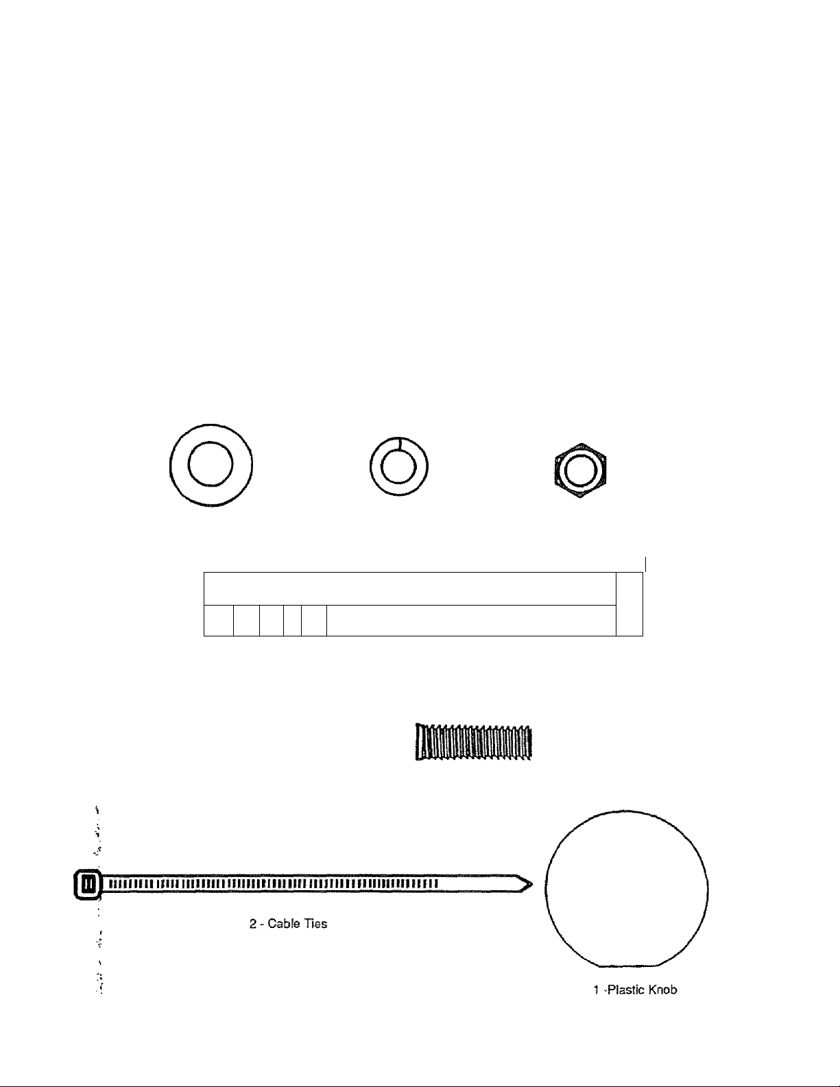
1 - 3/8 Inch
Flatwasher
1 1
1 11 1
CONTENTS OF PARTS BAG
Lockwasher
11 0
1 - 3/8 Inch
TOOLS REQUIRED FOR ASSEMBLY
1 - Knife (to cut carton and plastic ties)
2 - 1/2 inch Wrenches (or adjustable wrenches)
2 - 9/16 inch Wrenches (or adjustable wrenches)
2 - 3/4 inch Wrenches (or adjustable wrenches)
1 - Pair Pliers or Screwdriver (to spread cotter pin)
1 - 3/8 Inch
Hex Nut
^ ........................
/r^
D
2 - Spar© Shear Bolts
(5/16-18x2 inch Hex Head Boils)
fi
2-5/16-18
Locknuts
1 - 3/8 -16 X 2 Inch
Hex Head Bolt
ASSEMBLY
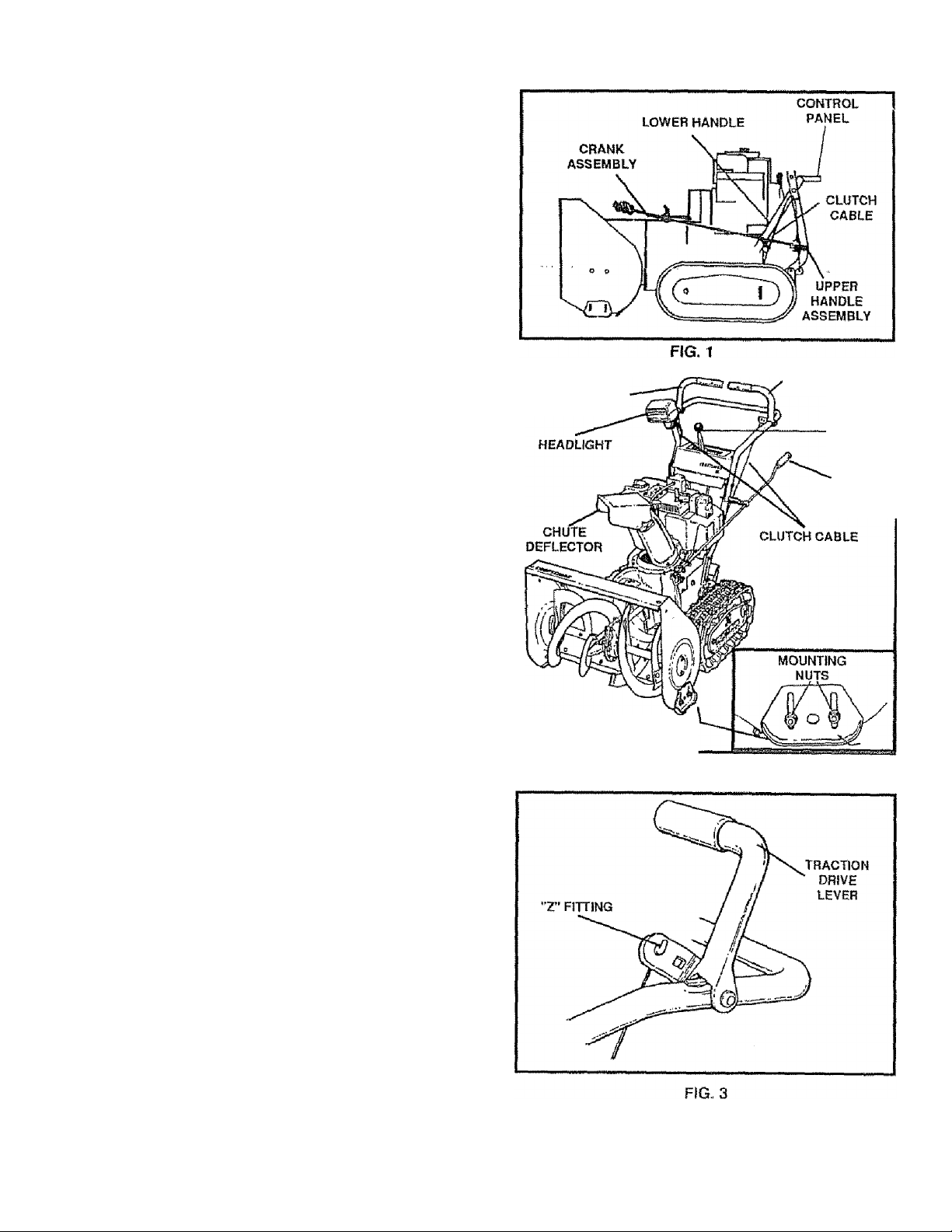
Figure 1 shows the snow thrower in the shipping position
Figure 2 shows the snow thrower completely assembled.
Reference to the right and left hand side of the snow
thrower is from the operator's position at the handle.
TO REMOVE SNOW THROWER
FROM CARTON (See Fig 1)
®
.....
Cut all four corners of the carton from top to bottom
and lay the panels flat.
• Cut the cable ties attached to the augers .
• Cut and discard the ties that secure the crank
assembly and place the assembly aside
® Remove the packing mate rial f rom t he co ntrol pan e I.
• Cut and discard the packing securing the clutch
cables to the lower handle,
® With two 9/16 inch wrenches, loosen (do not re
move) both bolts securing the upper and lower
handies Swing the upper handle into the operating
position.
NOTE: If the cables have become disconnected from the
clutch levers, reinstall the cables as shown in Figure 3.
® Tighten both bolts securely.
® Roll the snow thrower off the skid by pulling on the
handle.
NOTE; This snow thrower is equipped with a track drive
and can be hard to push when the engine is not running
it is easier to pull the snow thrower backward if it must be
moved without the engine running
The drive system may be tight when you first use your
snow thrower. It loosens up as you use it.
HOW TO SET UP YOUR SNOW
THROWER
AUGER DRIVE
LEVER
HEIGHT ADJUST
TRACTION DRIVE
LEVER
SHIFTER
LEVER
CRANK
ASSEMBLY
SKID
FIG. 2
TO SET THE SKID HEIGHT
For shipping, the height adjust skids are reversed To use
your snow thrower, you need to remove the height adjust
skids and reinstall as shown in Fig. 2 Then adjust the
height adjust skids for surface condilions as follows:
® Loosen the mounting nuts on the skids (See Fig 2)
® Place the extra shear bolts (in the parts bag) under
each end of the scraper bar near but not under the
skids.
® Push each skid up or down until it touches the
ground and the scraper bar is resting on each shear
bolt. Be sure the skids are set at the same height on
both sides
® Tighten the mounting nuts
ASSEMBLY
CAUTION: IF YOU ARE REMOVING
SNOW FROM ANY ROCKY OR UNEVEN
A
SKIDS DOWN. THIS WILL HELP TO PREVENT
ROCKS AND OTHER DEBRIS FROM BEING
PIpKED UP AND THROWN BY THE AUGER.
TO INSTALL UPPER HANDLE AND
CRANK ASSEMBLY
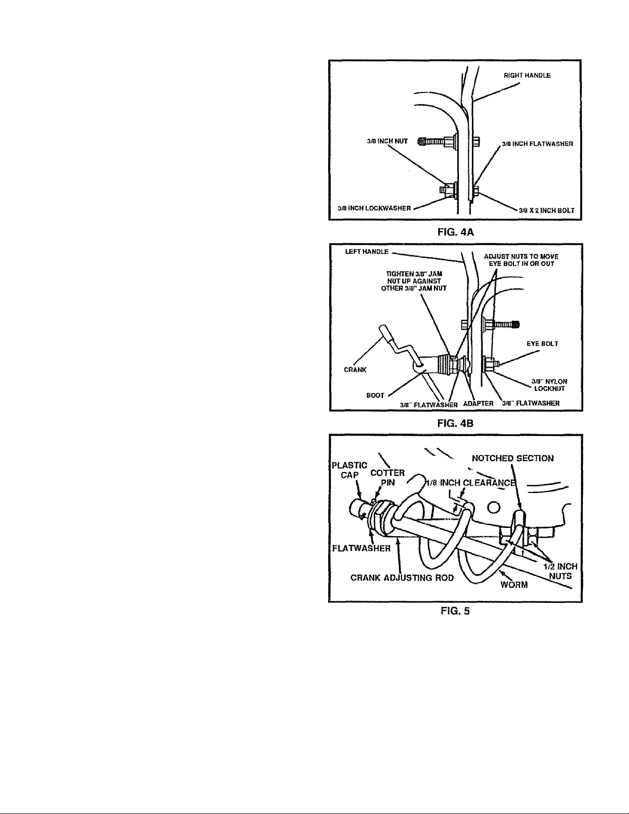
* 6n the right side of the handle, install and secure the
(ollowing parts (found in parts bag) in the lower
Randle hole as shown in figure 4A:
d - 3/8” X 2" bolt
.1 - 3/8" flatwasher & 3/8" lockwasher
•1 * 3/8" nut
* Remove the 3/8" nylon locknut and flatwasher from
the eye bolt assembly (on the chute crank assembly)
and adjust the two remaining 3/8" jam nuts, the fiat-
washer and the adapter on the eye bolt about half
vj/ay up the thread.
® install eye bolt through the lower hole on the left hand
side of the handle.
Install the 3/8" flatwasher and 3/8" nylon locknut
Iposely on the eye bolt, as shown.
Remove the plastic cap, the cotter pin and the flat-
washer from the wormed end of the crank assembly
and set aside (See Fig. 5).
Rotate the notched section of the discharge chute
toward the crank-adjusting rod.
Install the wormed end of the crank through the hole
in the adjusting rod and secure the end with the flat
washer and cotter pin, as shown in Figure 5
5end the ends of the cotter pin around the rod and reIgstall the plastic cap.
Tighten the eye bolt installed earlier. Keep the eye in
fine with the rod while tightening the inside nut se-
aireiy.
Tighten the outside 3/8" jam nut up against the other
3/8” Jam nut (See Fig. 4B),
Rotate the chute crank fully clockwise and fully
counter-clockwise. The discharge chute should ro
tate fully to the outer diameter of the worm and should
clear approximately 1/8" (See Fig 5), If the chute
crank needs to be adjusted, go to the Service and Adjgslments section on page 18.
NOTE: Be sure the crank does not touch the side of the
engine or the cover will be scratched.
SURFACES, RAISE THE FRONT OF THE
SNOW THROWER BY MOVING THE
TO CHECK/ADJUST
CONTROL CABLES
The control cables attached to the auger drive lever and
traction drive lever may need to be adjusted before you
use your snow thrower.
For instajctions on checking or adjusting the control
cables, see To Adjust The Clutch Control Cables paragrah on page 19.
ASSEMBLY
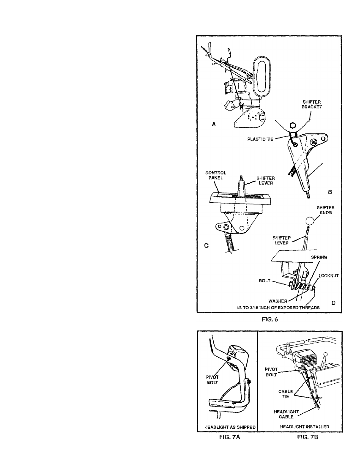
TO INSTALL THE SHIFTER LEVER KNOB
® Stand the snow thrower up on the front of the auger
housing, as shown in Fig 6A,
@ Cut the plastic tie which holds the shifter lever
assembly to the shift bracket {Fig 5B).
» Fiemove the locknut, washer, spring and bolt {Fig,
60).,
# Reposition the shifter iever into the slot in the
control panel, as shown in Fig, 6C and reinstall the
bolt, spring, washer and locknut.
a Tighten the locknut untii 1/8" to 3/16" (2 or 3 threads)
of the bolt protrude past the locknut,
a Thread the shifter lever knob onto the threaded end of
the shifter lever until it ¡slight (Fig. 6D)
a Move the shifter lever through ali the speeds to ensu re
proper tension of the spring., if the shifter lever sticks
in any of the notches, loosen the locknut 1/4 turn at a
time until the shifter lever moves freely,
TO INSTALL HEADLIGHT
The headlight is mounted on right side of upper handle and
is installed upside down for shipping purposes
@ Remove the pivot bolt (Fig. 7A). place headlight in
correct position (as shown in Fig. 7Band in Fig 2) and
retighten nut.
® Tie the headlight cable to upper and lower handles
with the plastic cable ties supplied in the parts bag by
threading the pointed ends of each tie through the
square ends and pulling tightly around the headlight
cable and the handle.
NOTE: One side of the plastic tie has small notches in it,
while the other side is smooth The notched side must be
on the inside of the loop which is formed when the ends are
put together
@ Try to loosen the cable tie If it can be loosened, it has
been attached with the smooth side on the inside of
the loop Remove the cable tie and reverse Us direction.
@ Cut off excess cable tie.
ASSEMBLY
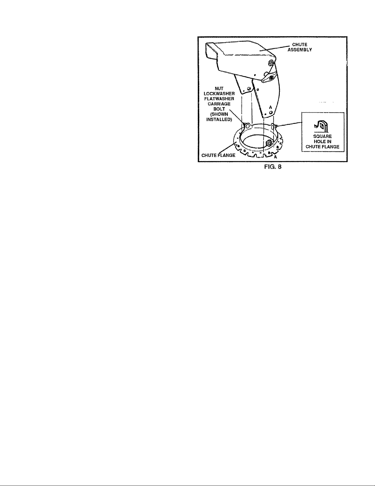
TO INSTALL CHUTE ASSEMBLY TO CHUTE FLANGE
% Remove the chute assembly from the carton
*
® psing a 1/2 inch wrench or adjustable wrench, re*
move the three (3} nuts, lockwashers, flafwashers
and carriage bolts from the chute flange.
• "pface the chute assembly over the outside of the
vchute ftange so that the "A" on the chute assembly
is next to the “A" on the chute flange This will align
all three holes correctly.
® From the inside of the chute flange, insert the three
/(3) carriage bolts {removed earlier) through the
^three sguare holes The sguare part of the carriage
bolls should fit into the square holes in the chute
jlange.
® Install the three (3) flatwashers, lockwashers and
nuts (removed earlier) on the carriage bolts.
’ CAUTION: IF ALL THE THREE {3) CARRIAGE
BOLTS CANNOT BE MOUNTED, THE HOLES
ARE NOT ALIGNED CORRECTLY. CHECK THE
. POSITION OF THE LETTER "A's*' ON THE
CHCITE assembly AND CHUTE FLANGE. THEY MUST
BE EACH OTHEFI IF LESS THAN THREE (3)
HoLeS line up, YOU HAVE MOUNTED THE CHUTE AS
SEMBLY INCORRECTLY AND SNOW COULD BE DiSCHf RQED TOWARD THE OPERATOR. REINSTALL THE
CHUTE ASSEMBLY IF NECESSARY.
10
OPERATION
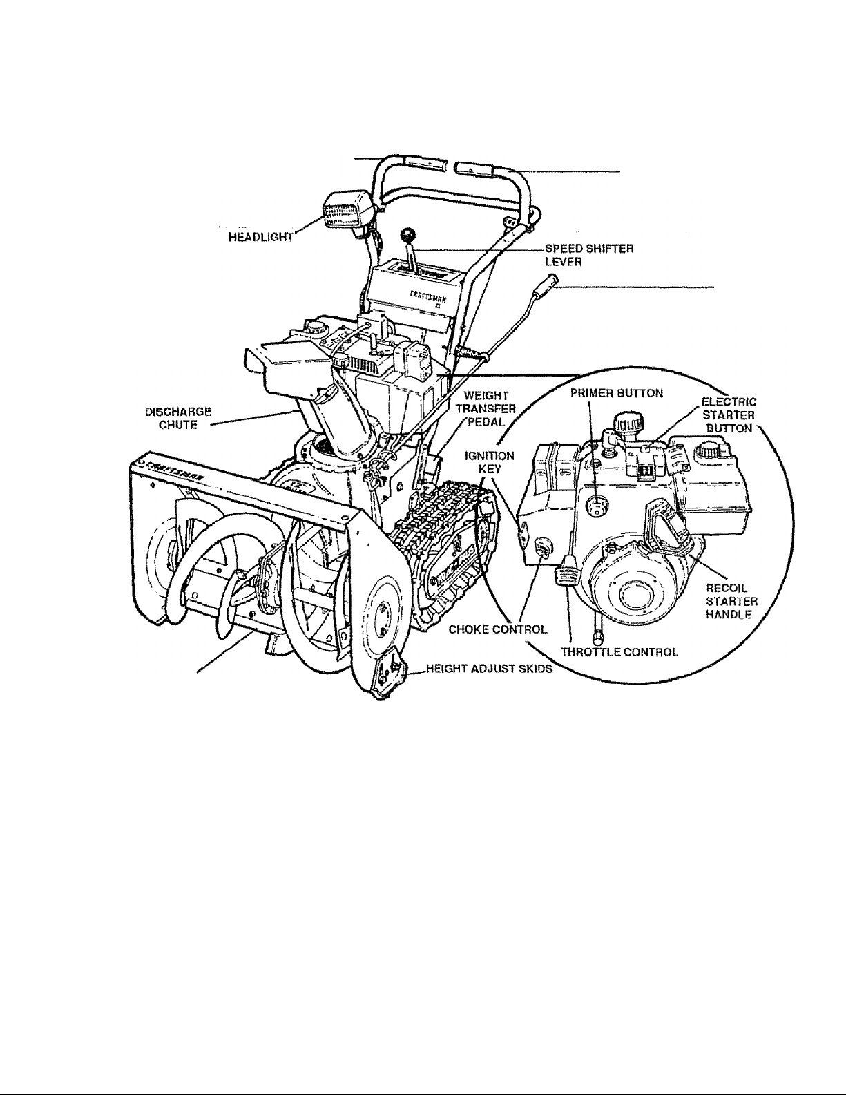
KNOW YOUR SNOW THROWER
READ TH!S OWNER’S MANUAL AND SAFETY RULES BEFORE OPERATiNG YOUR SNOW
THROWER. Compare the illustrations with your snow thrower to familiarize yourself with the location of various
controls and adjustments Save this manual for future reference.
AUGER DRÍVE
LEVER
CHUTE DEFLECTOR
r«^
TRACTION DRIVE
LEVER
CRANK
ASSEMBLY
SCRAPER BAR
FIG. 9
SEARS TRAC-PLUS SNOW THROWERS conform to the safely standards of the American National Standards
Institute.
AUGER DRIVE LEVER - Starts and stops the auger and
impeller (snow gathering and throwing).
TRACTION DRIVE LEVER - Propels the snow thrower
forward and in reverse.
SPEED SHIFTER LEVER - Selects the speed of the
snow thrower {6 speeds forward and 2 speeds reverse)
HEADLIGHT - Turns on whenever the engine is running.
CRANK ASSEMBLY - Changes the direction of snow
throwing through the discharge chute.
CHUTE DEFLECTOR - Changes the distance the snow
is thrown.
DISCHARGE CHUTE - Changes the direction the snow
is thrown
WEIGHT TRANSFER PEDAL- Engage for heavy snow
conditions, to keep the snow thrower from climbing drifts
and hard-packed snow. When released, it eases trans
port of the snow thrower.
HEIGHT ADJUST SKIDS - Adjusts the ground clearance
of the auger housing.
IGNITION KEY - Must be inserted to start the engine,
ELECTRIC STARTER BUTTON - Used to Start the en
gine using the 120 V electric starter.
RECOIL STARTER HANDLE - Starts the engine manu
ally,
CHOKE CONTROL - Used to start a cold engine
PRIMER BUTTON - Injects the fuel directly into the
carburetor or mainfold for last starts in coid weather
THROTTLE CONTROL - Controts the engine speed
11
OPERATION
The operation ol any snow throwercan resuil in foreign objects being thrown into the
eyes, which can result in severe eye damage. Always wear safety glasses or eye
shields while operating the snow thrower.
We recommend standard safety glasses or wide vision safety mask lor over your
glasses available at SEARS Retail or Catalog Stores.
HOW TO USE YOUR SNOW
THROWER
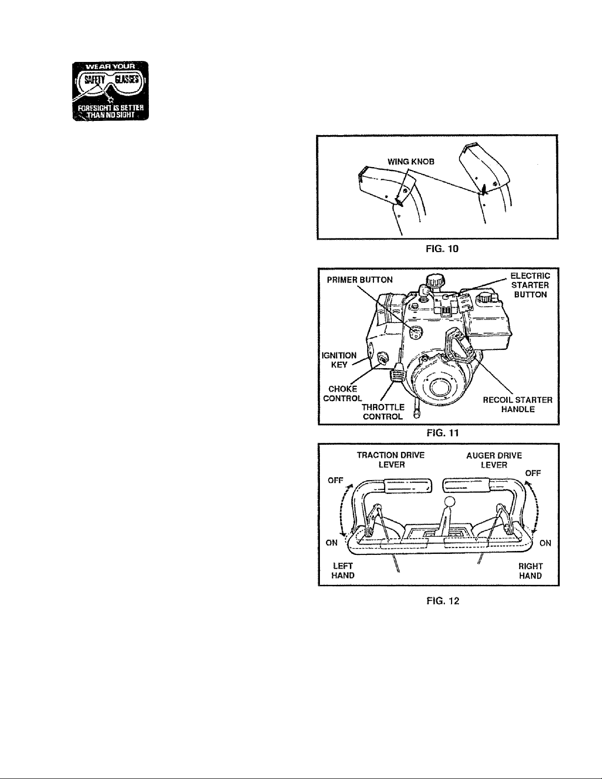
TO Control snow discharge
® Turn the crank assembly to set the direction of the
snow throwing.
® toosen the wing knob on the chute deflector and
ipove the deflector to set the distance Move the
deflector UP for more distance, DOWN for less
distance Then tighten the wing knob (Fig. 10)
TO Stop your snow thrower
® To slop throwing snow, release the auger drive
f^ver(See Fig. 12).
# to stop the track, release the traction drive lever
® To stop the engine, push the throttle control lever to
bfl and pull out the ignition key (See Fig. 11).
TO MOVE FORWARD AND BACKWARD
® 1^0 shiff, release the traction drive lever and move
the speed shifter lever to the speed you desire.
Ground speed is determined by snow conditions.
Select the speed you desire by moving the speed
shifter lever into the appropriate colored area on the
cpntrol panel.
> Red - Wet, Heavy. Slushy, Extra Deep
Amber - Moderate
White - Very Light
, Green - Transport only
® Bigage the traction drive lever (See Fig 12. left
hbnd) . Asthe snow thrower starts to move, maintain
a,firm hold on the handles, and guide the snow
thrower along the clearing path. Do not attempt to
push the snow thrower.
® fo move the snow thrower backward, move the
Speed shifter lever into first or second reverse and
'eipgage the traction drive lever (left hand)
IMPORTANT: DO NOT MOVE THE SPEED SHIFTER
LEVER WHILE THE TRACTION
; LEVER IS DOWN.
TO THROW SNOW
® pish down the auger drive lever (See Fig 12,
right hand).
® Release to stop throwing snow
A
rAlJTJON* RFAD OWNFR'R MAKliJAl
BEFORE OPERATING MACHINE.
NEVER DIRECT DISCHARGE TOWARD
(Up I # IT^« H Ibr In t I * V* * I III 4Mik Wlmm I H 11^ lUw
BEFORE UNCLOGGING DISCHARGE
CHUTE OR AUGER HOUSING AND
BEFORE LEAVING THE MACHINE.
’Tup FNCINF
12
OPERATION
TO USE WEIGHT TRANSFER SYSTEM
in hard packed or heavy snow conditions, conventional
snow throwers tend to ride up and leave uneven mou nds
ol snow behind. For these conditions, your new tracked
snow thrower has a unique weight transfer system (See
Fig. 13) designed to minimize ride-up
Stepping on the weighttransferpedal shifts more weight
to the auger housing. This weight transfer keeps the
snow thrower in contact with the ground and reduces
ride-up on ice and snow,
In lighter snow conditions or when transporting, you
should release the weight transfer system for easier
steering
® To use the weight transfer, hold the upper handle
firmly and push down on the weight transfer pedal
{See Fig 13) with the ball of your foot
® To release, pull up on the weight transfer pedal with
the top of your foot .
NOTE: The weight transfer system will not work if the
auger housing height adjust skids are adjusted to the
highest position
FIG.13
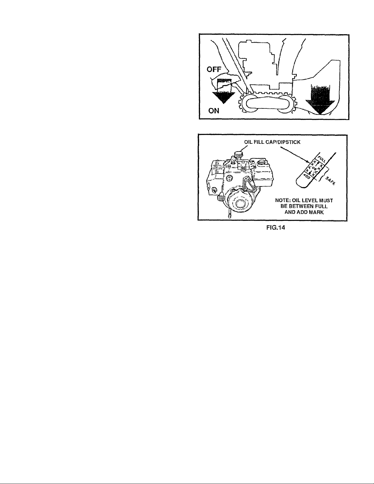
BEFORE STARTING THE ENGINE
FILL/ ADD OIL:
The engine on this snow thrower was shipped without
oil Add oil before you start the engine Remove the oil
fill cap/dipstick and fill the crank case to FULL line on
dipstick (26 ounces) (See Fig, 14) with S A E.. 10 W-30
motor oil (or equivalent) Do not overfill. Tighten the till
cap/dipstick securely each time you check the oil level.
NOTE: S.A E 5W-30 motor oil may be used to make
starting easier in areas where temperature is consis
tently 20° F or lower
FILL GAS:
WARNING: Experience indicates that alcohol blended
fuels (called gasoho! or using ethanol or methanol) can
attract moisture which leads to separation and formation
of acids during storage Acidic gas can damage the fuel
system of an engine while in storage
To avoid engine problems, the fuel system should be
emptied before storage for 30 days or longer Start the
engine and let it run until the fuel lines and carburetor are
empty. Use the carburetor bowl drain to empty residual
gasolinefromthe float chamber (See Fig 42) Use fresh
fuel next season (See Storage insirudionsfor additional
information)
Never use engine or carburetor cleaner products in the
fuel lank or permanent damage may occur
Fill the fuel tank with clean, fresh, unleaded grade
automotive gasoline. Be sure that the container you pour
the gasoline from is clean and free from rust or other
foreign particles. Never use gasoline that may be stale
from long periods of storage in the container
CAUTION: GASOLINE IS FLAMMABLE
A
DO NOT FILL FUEL TANK WHILE SNOW
THROWER IS RUNNING,WHEN IT IS HOT, OR
WHEN SNOW THROWER IS IN AN ENCLOSED
AREA.
KEEP AWAY FROM OPEN FLAME OR AN ELEC
TRICAL SPARK AND DO NOT SMOKE WHILE
FILLING THE FUEL TANK.
NEVER FILL THE TANK COMPLETELY. FILL
THETANKTOWITHIN 1/4"-1/2" FROMTHETOP
TOPROVIDESPACEFOR EXPANSION OF FUEL.
ALWAYS FILL FUEL TANK OUTDOORS AND
USE A FUNNEL OR SPOUT TO PREVENT SPILL
ING.
MAKE SURE TO WIPE UP ANY SPILLED FUEL
BEFORE STARTING THE ENGINE
STORE GASOLINE IN A CLEAN, APPROVED
CONTAINER AND KEEP THE CAP IN PLACE ON
THE CONTAINER-
AND CAUTION MUST BE USED WHEN
HANDLING OR STORING IT.
13
OPERATION
TO STOP ENGINE
® To Slop engine, move tfie throttle control lever to
STOP position and remove key Keep the key in a
safe place. The engine will not start without the key
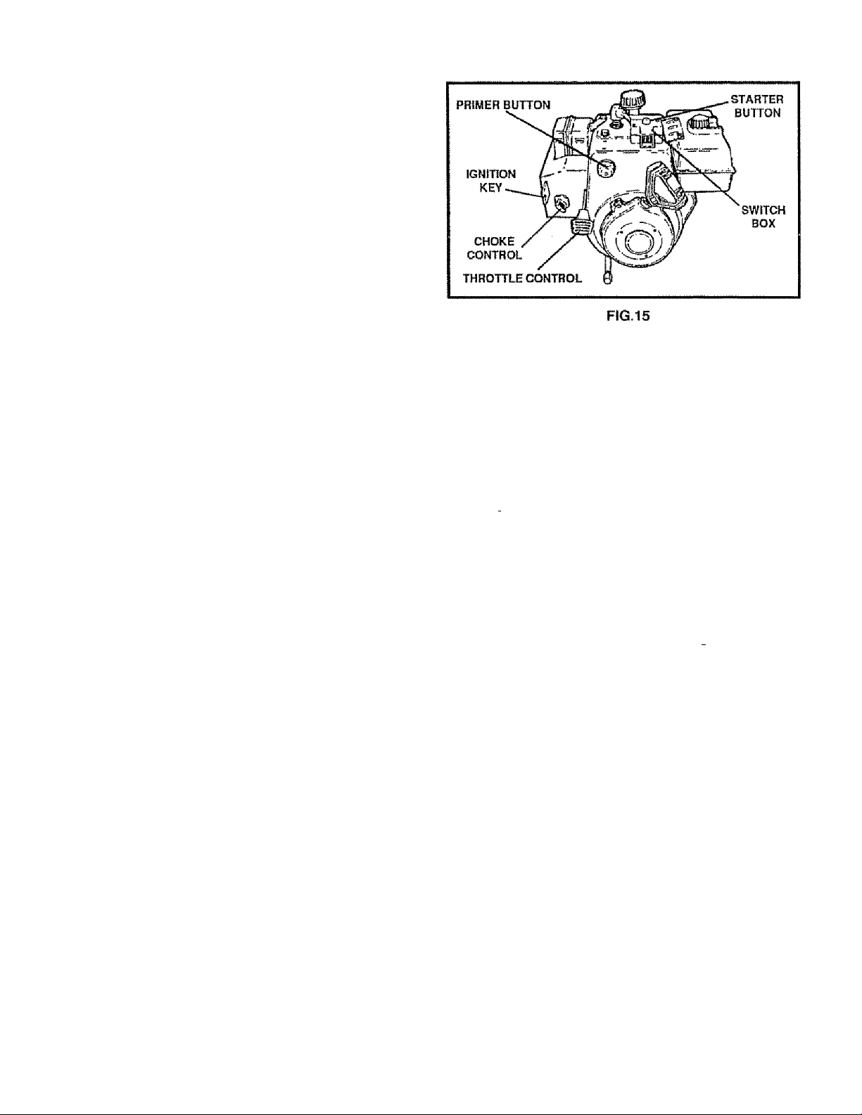
TO START ENGINE (Electric Starter)
Be sure that the engine has sufficient oil. The snow/
thrower engine is equipped with a 120 volt A C electric
starter and recoil starter. Before starling the engine, be
certaifi that you have read the following information:
COtD START (Se© Fig. 15)
® ^e sure the auger drive and traction drive levers
are in the disengaged RELEASED position
® Move the throttle control up to FAST position.
® Remove the keys from the plastic bag. Insert one
key into the ignition slot Be sure it snaps into place.
E)0 NOT TURN KEY. Keep the second key in a
safe place,
® l|otate the choke knob to FULL choke position.
® Connect the power cord to the switch box on the
engine.
® Plug the other end of the power cord into a three
iple, grounded 120 volt A C receptacle,
® Press primer button in cold weather. Press fwo-
t^ree times while keeping yourfinger overthe vent
hole on the primer button Additional priming may
be necessary for the first start if the temperature is
below 15® F,
® Rush down on the starter button until the engine
starts Do not crank for more than 10 seconds at a
tirne. This electric starter is thermally protected, if
overheated it will stop automatically and can be
restarted only when it has cooled !o a sate tem
perature (a wait of about 5 to 10 minutes is re
quired)
® When the engine starts, release the starter button
and slowly rotate the choke to OFF position. It the
engine falters, rotate the choke to FULL and then
gradually to OFF,
® disconnect the powercord from the receptacle first
änd then from switch box on engine,
NOTE; Allow the engine to warm up for a few minutes
because the engine will not develop full power until it
reaches operating temperature
® Run the engine at full throttle (FAST) speed when
throwing snow.
CAUTION: THIS STARTER IS EQUIPPED
WITHATHREE-WIREPOWER CORD AND
A
£)] I Alili*) ICS DCiCSi/iKIICI*) AITCT
ruUIji ArlU Id UcDi^piilU lU UHcHAIC
ON 120 VOLT AC HOUSEHOLD CUR
RENT. IT MUST BE PROPERLY GROUNDED AT
ALL TIMES TO AVOID THE POSSIBILITY OF ELEC
TRICAL SHOCK, WHICH MAY BE INJURIOUS TO
OPERATOR. FOLLOW ALL INSTRUCTIONS
nARPFllI I Y AR *5FT FORTH IN THF "TO i5taqt
W"% • III«#* til« Iwt • fpHt I P I R t * I a«« f I ■ Rm I NMF 4 IT^m f «
ENGINE“ SECTION. DETERMINE THAT YOUR
HOUSE WIRING iS A THREE-WIRE GROUNDED
SYSTEM. ASK A LICENSED ELECTRICIAN IF YOU
ARE NOT SURE. IF YOUR HOUSE WIRE SYSTEM
IS NOT A THREE-WIRE SYSTEM, DO NOT USE
THIS ELECTRIC STARTER UNDER ANY CONDI
TIONS. IF YOUR SYSTEM IS GROUNDED AND A
THRFF-HOI F RFf'FPTAPI F ari e
I I I it a ÌMn*3kmri a a RmvRnM it R Rmii RiMta R RipP I R w Rwa a Mn W itili R Rw».*'■ Rn^ Ren Rw
AT THE POINT YOUR STARTER WILL NORMALLY
LICENSED ELECTRICIAN.
WHEN CONNECTING 120 VOLT AC POWER CORD,
ALWAYS CONNECT THE CORD TO THE SWITCH
unti ON THF FNOINF FIR^iT THFN PI HO THF
M* Vw' <r\ Va'I H <11 !»■ Rh** H V»1 ■ l Rm 1 III VaR R y W * <9m»’R It 9 V» I R R Rm
OTHER END INTO THE THREE-HOLE GROUNDED
RECEPTACLE.
WHEN DISCONNECTING POWER CORD, ALWAYS
UNPLUG THE END IN THE THREE-HOLE
GROUNDED RECEPTACLE FIRST.
PP I IQI^n r^MP CMnt II ¥\ PP IKIQTAI I Pfi PV A
0P UDPM) wi«P DlfWR>J!L.li/ 1C5P ¡l’Io I Ml»I-*PM PT M
WARM START
If restating a warm engine after a short shutdown, leave
choke'at OFF and do not push the primer button
14
 Loading...