

Page 1
Operator's Manual
Snow Thrower
9.5 Horsepower
Electric Start
29" Dual Stage
Model 536.881951
CAUTION: Before usingthis product,
read this manual and follow all of its
Safety Rules and Operating Instructions.
Manual del usario
Quitanieves
9.5 caballos de fuerza (hp)
Arranque el_ctrico
29" Biet_pico
Modelo 536.881951
PRECAUCION: Antes de usar este producto,
lea este manual y siga todas ias reglas de
seguridad e instruccionesde operaci6n.
Sears, Roebuck and Co., Hoffman Estates, IL 60179 U.S.A.
198511 Rev. 2 07.27.95 BY www.sears.com/craftsman Printed in U.S.A.
Page 2
WARRANTY STATEMENT ......
SAFETY RULES ...............
INTERNATIONAL SYMBOLS ....
ASSEMBLY ...................
OPERATION ..................
MAINTENANCE ...............
SERVICE AND ADJUSTMENT ..
LIMITED TWO-YEAR WARRANTY ON CRAFTSMAN SNOW THROWER
For two years from the date of purchase, when this Craftsman Snow thrower ismaintained,
lubricated, and tuned up according to the operating and maintenance instructions in the
owner's manual, Sears will repair, free of charge, any defect in material or workmanship.
If this Craftsman Snow thrower is used for commercial or rental purposes, this warranty ap-
plies for only 90 days from the date of purchase.
This warranty does not cover the following:
• Items which become worn during normal use, such as spark plugs, drive beltsand shear
pins.
• Repair necessary because of operator abuse or negligence, including bent crankshafts
and the failure to maintain the equipment according to the instructions contained in the
owner's manual.
WARRANTY SERVICE IS AVAILABLE BY RETURNING THE CRAFTSMAN SNOW
THROWER TO THE NEAREST SEARS SERVICE CENTER IN THE UNITED STATES,
THIS WARRANTY APPLIES ONLY WHILE THIS PRODUCT IS IN USE IN THE UNITED
STATES.
This warranty gives you specific legal rights, and you may also have other rights which may
vary from state to state.
Sears, Roebuck and Co., D817WA, Hoffman Estates. IL 60179
2 STORAGE .................... 28
2 TROUBLESHOOTING TABLE ... 29
4 REPAIR PARTS ............... 33
6 ENGINE REPAIR PARTS ....... 51
10 SPANISH (ESPANOL) .......... 56
16 PARTS ORDERING/SERVICE . .
18 BACK COVER
,_ LOOK FOR THIS SYMBOL TO POINT OUT IMPORTANT SAFETY PRECAUTIONS.
Engine Exhaust, some of its constituents, and
certain vehicle components contain or emit
chemicals known to the Stste of California to
cause cancer and birth defects or other repro-
ductive harm.
Battery posts, terminals and related accessories
contain lead and lead compounds, chemicals
known to the State of California to cause cancer
and birth defects or other reproductive harm.
WASH HANDS AFTER HANDLING.
IT MEANS-- ATTENTIONlll BECOME ALERTtll YOUR SAFETY IS INVOLVED.
_ WARNING: Always discon-
make contact with spark plug to
prevent accidental starting during:
Preparation, Maintenance, or Stor-
age of your snow thrower.
IMPORTANT: Safety standards re-
quire operator presence controls to
minimize the risk of injury. Your snow
thrower is equipped with such controls.
Do not attempt to defeat the function of
the operator presence control under any
circumstances.
2
nect the spark plug wire
and place it whore it cannot
Page 3
TRAINING
1. Read this operating and service instruction
manual carefully. Be thoroughly familiar
with the controls and the proper use of the
snow thrower. Know how to stop the snow
thrower and disengage the controls quick-
ly.
2. Never allow children to operate the snow
thrower. Never allow adults to operate the
snow thrower without proper instruction.
3. Keep the area of operation clear of all per-
sons, particutarly small children and pets.
4. Exercise caution to avoid slipping or falling
especially when operating in reverse.
PREPARATION
1. Thoroughly inspect the area where the
snow thrower is to be used and remove all
doormats, sleds, boards, wires, and other
foreign objects.
2. Disengage all clutches before starting the
engine (motor).
3. Do not operate the snow thrower without
wearing adequate winter outer garments.
Wear footwear that will improve tooting on
slippery surfaces.
4. Handle fuel with care; it is highly flam-
mable.
a. Use an approved fuel container.
b. Never remove fuel tank cap or add fuel
to a running engine (motor) or hot en-
gine (motor).
c. Fill fuel tank outdoors with extreme
care. Never fill fuel tank indoors.
d. Replace fuel cap securely and wipe up
spilled fuel.
e. Never store fuel or snow thrower with
fuel in the tank inside of a building
where fumes may reach an open flame
or spark.
f. Check fuel supply before each use, al-
lowing space for expansion as the heat
of the engine (motor) and/or sun can
cause fuel to expand.
5. For all snow throwers with electnc starting
motors use electric starting extension
cords cer_fled CSNUL. Use only with a re-
ceptacle that has been installed in accord-
ance with local inspection authonties.
6. Never attempt to make any adjustments
while the engine (motor) is running (except
when specifically recommended by manu-
facturer).
7. Let engine (motor) and snow thrower ad-
just tooutdoor _emperatures before sta_ng
to clear snow.
8_
Always wear safety glasses or eye shields
during operation or while performing an ad-
justment or repair to protect eyes from
foreign objects that may be thrown from the
snow thrower.
OPERATION
1. Do not operate this snow thrower if you are
taking drugs or other medication which can
cause drowsiness or affect your ability to
operate this snow thrower.
2. Do not use the snow thrower if you are
mentally or physically unable to operate the
snow thrower safely.
3. Do not put hands or feet near or under ro-
tating parts. Keep clear of the discharge
opening at all times.
4. Exercise extreme caution when operating
on or crossing gravel drives, walks or
roads. Stay alert for hidden hazards or
traft]c.
5. After striking a foreign object, stop the en-
gine (motor), remove the wire from the
spark plug, thoroughly inspect snow
thrower for any damage, and repair the
damage before restarlJng and operating
the snow thrower.
6. If the snow thrower should start to vibrate
abnormally, stop the engine (motor) and
check immediately for the cause. Vibration
is generally a warning of trouble.
7. Stop the engine (motor) whenever you
leave the operating position, before un-
clogging the auger/impeller housing or dis-
charge chute and when making any
repairs, adjustments, or inspeclJons.
8. When cleaning, repairing, or inspecting,
make certain the auger/impeller and all
moving parts have stopped and all controls
are disengaged. Disconnect the spark plug
wire and keep the wire away from the spark
plug to prevent accidental starting.
9. Take all possible precautions when leaving
the snow thrower unattended. Disengage
the auger/ impeller, stop engine (motor),
and remove key.
10. Do not run the engine (motor) indoors, ex-
cept when starting the engine (motor) and
for transportJng the snow thrower in or out
of the _ilding. Open the outside doors; ex-
haust fumes are dangerous (containing
CARBON MONOXIDE, an ODORLESS
and DEADLY GAS).
11. Do not clear snow across the face of
slopes. Exercise extreme cauiton when
changing direction on slopes. Do not at-
tempt to clear steep slopes.
12. Never operate the snow thrower without
proper guards, plates or other safety pro-
tective devices in place.
3
Page 4
13.
Neveroperatethesnowthrowernearen-
closures,automobiles,windowwells,drop-
offs,andthelikewithoutproperadjustment
ofIhe snow discharge angle. Keep children
and pets away.
14.
Do not overload the snow thrower capacity
by attempting to clear snow at too fast a
rate.
15.
Never operate the snow thrower at high
transport speeds on slippery surfaces.
Look behind and use care when backing
up.
16.
Never direct discharge at bystanders or
allow anyone in front of the snow thrower.
17.
Disengage power to the collector/impeller
when snow thrower is Iransported or not in
use.
18.
Use only attachments and accessories ap-
proved by the manufacturer of the snow
thrower (such as tire chains, elecfric start
kits, ect.).
19.
Never operate the snow thrower without
good visibility or light. Always be sure of
your footing and keep a firm hold on the
handles. Walk;never run.
20.
Do not over-reach. Keep proper footing
and balance at all times.
21.
Do not attempt to use snow thrower on a
roof.
MAINTENANCE AND STORAGE
1. Check shear bolts and other bolts at fre-
quent intervals for proper tightness to be
sure the snow thrower is in safe working
condition.
2. Never store the snow thrower with fuel in
the tank inside a building where ignition
sources are present such as hot water and
space heaters, clothes dryers, and the like.
Allow the engine (motor) to coo! before
storing in any enclosure.
3. Always refer to operator's guide instruc-
tions for important details if the snow
thrower is to be stored for an extended
period.
4. Maintain or replace safety and ins_uction
labels, as necessary.
5. Run the snow thrower a few minutes after
throwing snow to prevent freeze-up of the
auger/impeller.
,_ WARNING: This snow thrower is
Caution should be exercised while using on
steep sloping surfaces. DO NOT USE
SNOW THROWER ON SURFACES ABOVE
GROUND LEVEL such as roofs of resi-
dences, garages, porches or other such
structures or buildings.
for use on sidewalks, driveways
and other ground level surfaces.
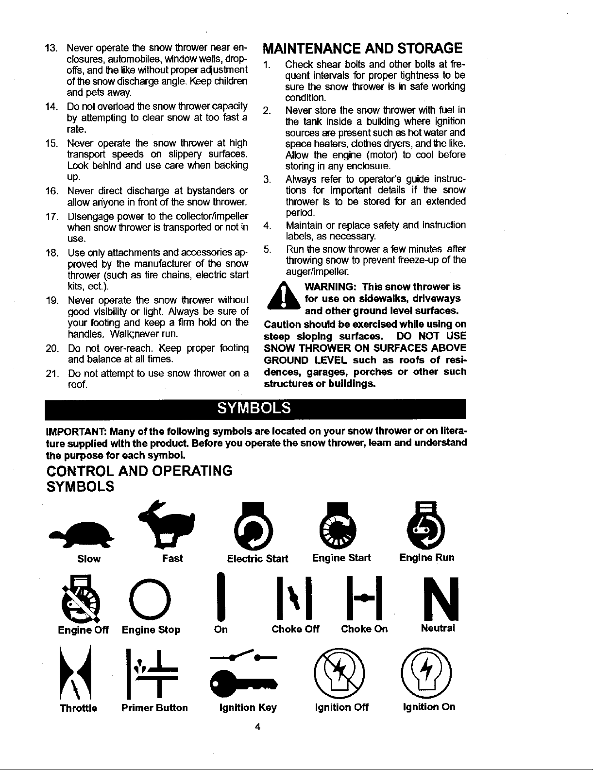
IMPORTANT: Many of the following symbols are locked on your snow thrower or on litera-
ture supplied with the product. Before you operate the snow thrower, leam and understand
the purpose for each symbol.
CONTROL AND OPERATING
SYMBOLS
Slow Fast Electric Start Engine Start Engine Run
I I-I N
Engine Off Engine Stop On Choke Off Choke On Neutral
®G
Throttle Primer Button Ignition Key
Ignition Off Ignition On
Page 5
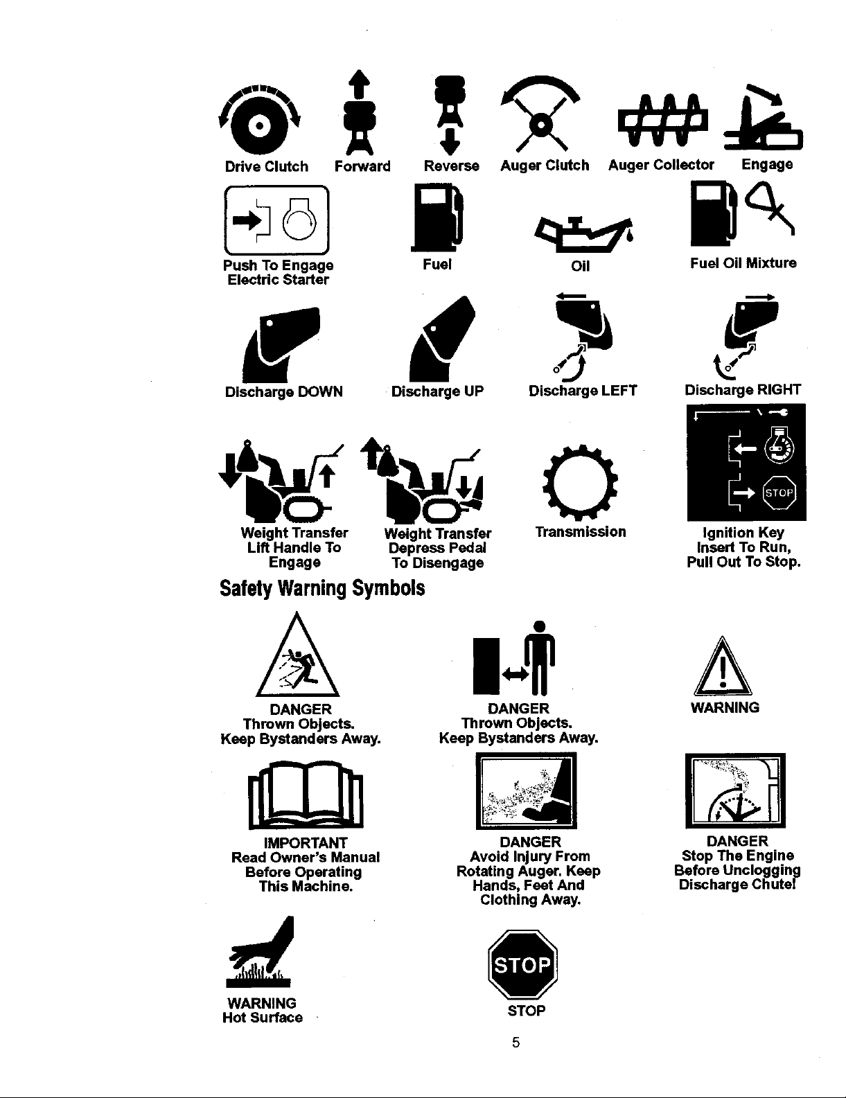
DriveClutch Forward Reverse
AugerClutch AugerCollector Engage
PushToEngage Fuel
Oil FuelOilMixture
ElectricStarter
DischargeDOWN DischargeUP
DischargeLEFT DischargeRIGHT
|,M
Weight Transfer Weight Transfer Transmission Ignition Key
Lift Handle To Depress Pedal Insert To Run,
Engage To Disengage Pull Out To Stop.
SafetyWarningSymbols
DANGER DANGER WARNING
Thrown Objects. Thrown Objects.
Keep Bystanders Away. Keep Bystanders Away.
IMPORTANT
Reed Owner's Manual
Before Operating
This Machine.
WARNING
Hot Surface
Rotating Auger. Keep
DANGER
Avoid Injury From
Hands, Feet And
Clothing Away.
STOP
5
DANGER
Stop The Engine
Before Unclogging
Discharge Chutei
Page 6
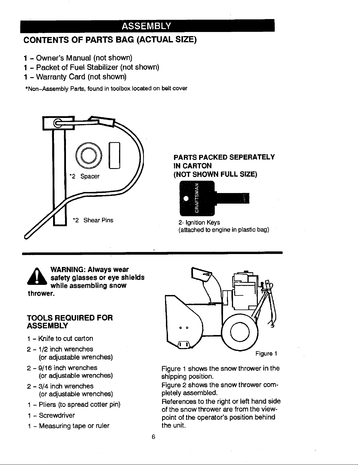
CONTENTS OF PARTS BAG (ACTUAL SIZE)
1 - Owner's Manual (not shown)
1 - Packet of Fuel Stabilizer (not shown)
1 - Warranty Card (not shown)
*Non-Assembly Parts, found in toolbox located on belt cover
PARTS PACKED SEPERATELY
IN CARTON
(NOT SHOWN FULL SIZE)
d_lb WARNING: Always wear
thrower.
safety glasses or eye shields
while assembling snow
TOOLS REQUIRED FOR
ASSEMBLY
1 - Knife to cut carton
2 - 1/2 inch wrenches
(or adjustable wrenches)
2 - 9/16 inch wrenches
(or adjustable wrenches)
2 - 3/4 inch wrenches
(or adjustable wrenches)
1 - Pliers (to spread cotter pin)
1 - Screwdriver
1 - Measuring tape or ruler
2- Ignition Keys
(attached to engine in plastic bag)
Figure 1
Figure 1 shows the snow thrower in the
shipping position.
Figure 2 shows the snow thrower com-
pletely assembled.
References to the right or left hand side
of the snow thrower are from the view-
point of the operator's position behind
the unit.
6
Page 7
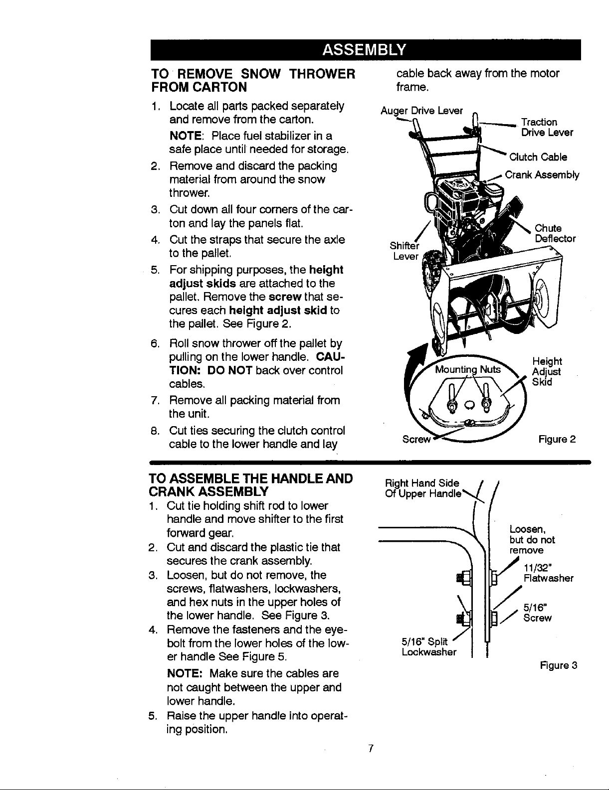
TO REMOVE SNOW THROWER
FROM CARTON
,
Locate all parts packed separately
and remove from the carton.
NOTE: Place fuel stabilizer in a
safe place until needed for storage.
.
Remove and discard the packing
material from around the snow
thrower.
Cut down all four corners of the car-
3,
ton and lay the panels flat.
4.
Cut the straps that secure the axle
to the pallet.
5.
For shipping purposes, the height
adjust skids are attached to the
pallet. Remove the screw that se-
cures each height adjust skid to
the pallet. See Figure 2.
,
Roll snow thrower off the pallet by
pulling on the lower handle. CAU-
TION= DO NOT back over control
cables.
,
Remove all packing material from
the unit.
8.
Cut ties securing the clutch control
cable to the lower handle and lay
cable back away from the motor
frame.
Auger Drive Lever n
"'-_ - L_ Traction
_ Drive Lever
_"Clutch Cable
nk Assembly
_ Chute
Lever
Scre_ Figure 2
_11_ Deflect°r
Height
Adjust
Skid
TO ASSEMBLE THE HANDLE AND
CRANK ASSEMBLY
1, Cut tie holding shift rod to lower
handle and move shifter to the first
forward gear.
2. Cut and discard the plastic tie that
secures the crank assembly.
3. Loosen, but do not remove, the
screws, flatwashers, Iockwashers,
and hex nuts in the upper holes of
the lower handle. See Figure 3.
4. Remove the fasteners and the eye-
bolt from the lower holes of the low-
er handle See Figure 5.
NOTE: Make sure the cables are
not Caught between the upper and
lower handle.
5. Raise the upper handle into operat-
ing position.
Of Upper Handle
RightHandSide _, /
5/16"
Loosen,
but do not
remove
11132"
Flatwasher
5/16"
Screw
Figure 3
Page 8
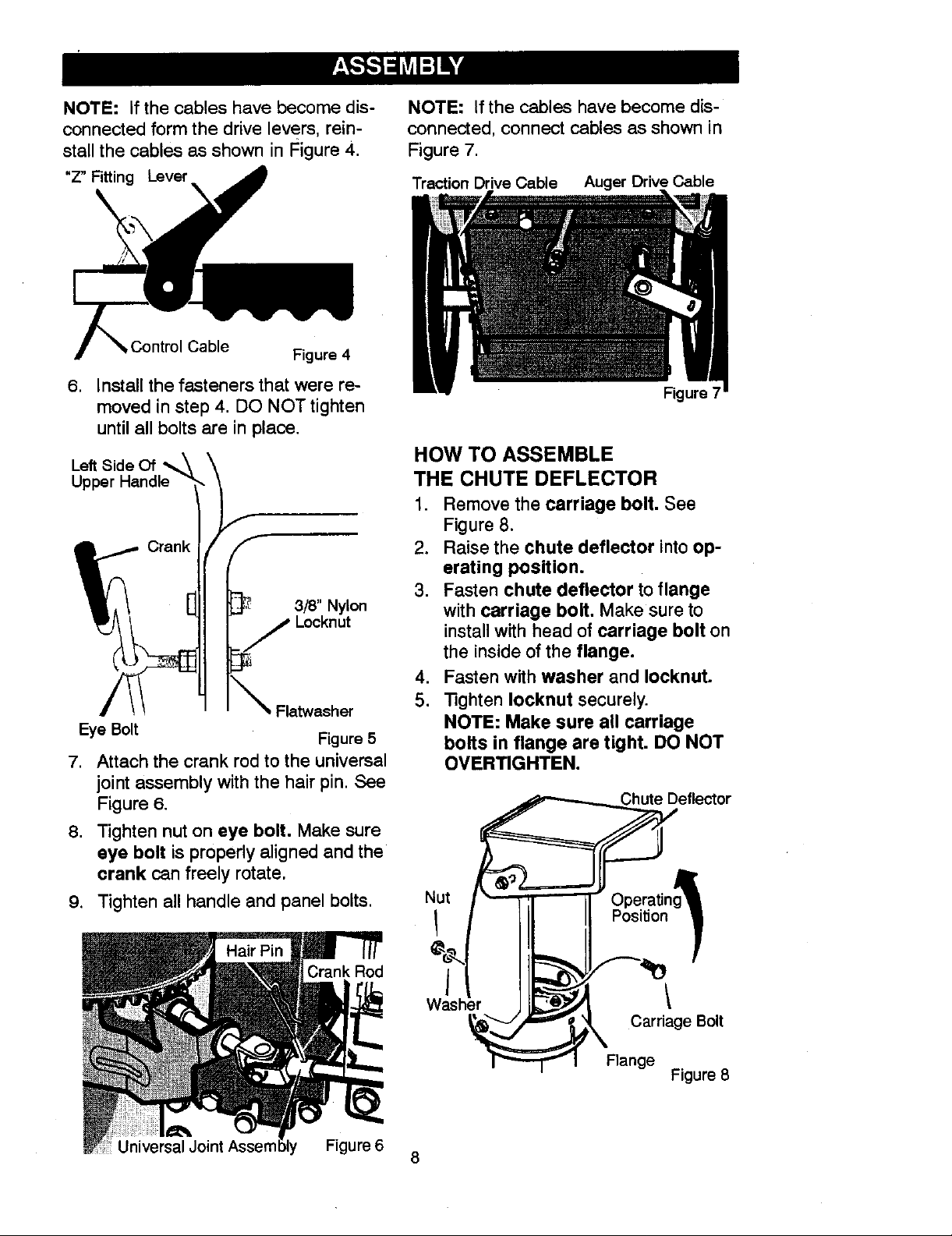
NOTE: If the cables have become dis-
connected form the drive levers, rein-
stall the cables as shown in Figure 4.
"z" Fitting Lever
Control Cable Figure 4
NOTE: If the cables have become dis-
connected, connect cables as shown in
Figure 7.
Traction Drive Cable Auger Drive Cable
6, Install the fasteners that were re-
moved in step 4. DO NOT tighten
until all bolts are in place.
Left Side Of
3/8" Nylon
Eye Bolt Figure 5
7. Attach the crank rod to the universal
joint assembly with the hair pin. See
Figure 6.
8. Tighten nut on eye bolt, Make sure
eye bolt is properly aligned and the
crank can freely rotate.
9. Tighten all handle and panel bolts.
Figure 7
HOW TO ASSEMBLE
THE CHUTE DEFLECTOR
1. Remove the carriage bolt. See
Figure 8.
2. Raise the chute deflector into op-
erating position.
3. Fasten chute deflector to flange
with carriage bolt. Make sure to
install with head of carriage bolt on
the inside of the flange.
4. Fasten with washer and Iocknut.
5. Tighten Iocknut securely.
NOTE: Make sure all carriage
bolts in flange are tight. DO NOT
OVERTIGHTEN.
Nut
Crank Rod
Universal Figure 6
Was
Carriage Bolt
Flange
Figure 8
8
Page 9
HOW TO SET THE SKID HEIGHT
Your snow thrower is equipped with
height adjust skids on the outside of the
auger housing. To adjust the skid
height for different conditions, see To
Adjust Skid Height paragraph in the
Service And Adjustment section.
HOW TO SET THE LENGTH OF THE CABLES
The cables were adjusted at the factory
and no adjustments should be neces-
sary. However, after the handles are put
in the operating position, the cables can
be too tight or too loose. If an adjust-
ment is necessary, see "How To Check
And Adjust The Cables" in the Service
And Adjustment section.
_,- CHECKLIST
Before you operate your new snow
thrower, to ensure that you receive the
best performance and satisfaction from
this quality product, please review the
following checklist:
_" All assembly instructions have been
completed.
,_" The discharge chute rotates freely.
No remaining loose parts in carton.
_" Check the fasteners. Make sure all
fasteners are tight.
_" On electric start models, the unit was
shipped with the starter cord plugged
into the engine. Before operating, un-
plug the starter cord from the engine.
While learning how to use your snow
thrower, pay extra attention to the fol-
lowing important items:
Engine oil is at proper level.
Make sure gas tank is filled properly
with clean, fresh, unleaded gasoline.
Become familiar with all controls-
their location and function. Operate
controls before starting engine.
9
Page 10
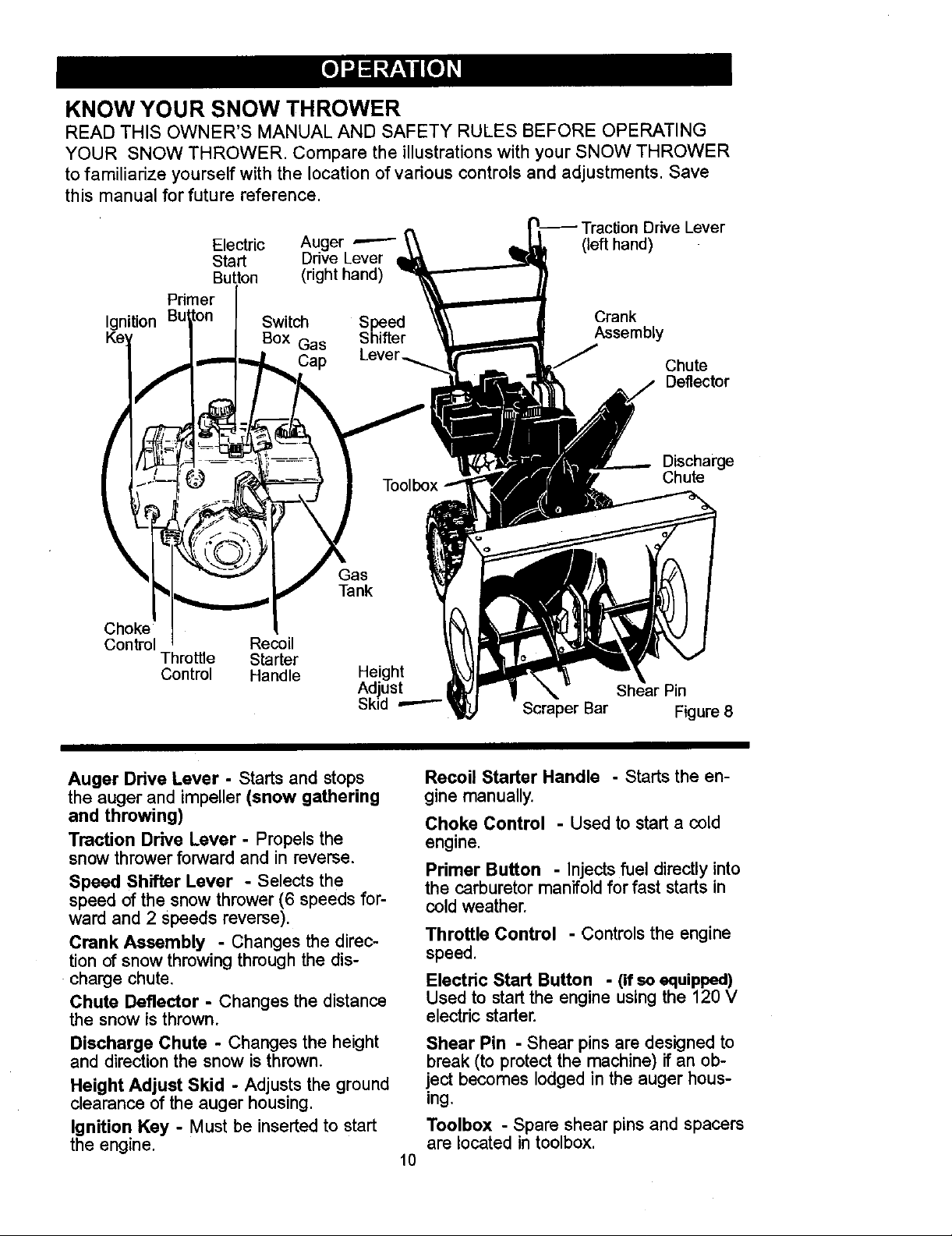
KNOW YOUR SNOW THROWER
READ THIS OWNER'S MANUAL AND SAFETY RULES BEFORE OPERATING
YOUR SNOW THROWER. Compare the illustrations with your SNOW THROWER
to familiarize yourself with the location of various controls and adjustments. Save
this manual for future reference.
Drive Lever
Electric Auger ,-----"
Start Drive Lever
Button (right hand)
Primer
Ignition Butlt°n Switch Speed
Key I Box Gas Shifter
/ ,,,__--- ..,. _, Cap Lever.
Crank
Assembly
Chute
Deflector
,_ - ,
Discharge
Chute
Choke
Control _,ecoil
Throttle Starter
Control Handle Height
Adjust Shear Pin
Sk d ==--- Scraper Bar
Auger Drive Lever - Starts and stops
the auger and impeller (snow gathering
and throwing)
Traction Drive Lever. Propels the
snow thrower forward and in reverse.
Speed Shifter Lever - Selects the
speed of the snow thrower (6 speeds for-
ward and 2 Speeds reverse).
Crank Assembly - Changes the direc-
tion of snow throwing through the dis-
charge chute.
Chute Deflector - Changes the distance
the snow is thrown.
Discharge Chute - Changes the height
and direction the snow is thrown.
Height Adjust Skid - Adjusts the ground
clearance of the auger housing.
Ignition Key - Must be inserted to start
the engine.
Figure 8
Recoil Starter Handle - Starts the en-
gine manually.
Choke Control - Used to start a cold
engine.
Primer Button - Injects fuel directly into
the carburetor manifold for fast starts in
cold weather.
Throttle Control - Controls the engine
speed.
Electric Start Button - (if so equipped)
Used to start the engine using the 120 V
electric starter.
Shear Pin - Shear pins are designed to
break (to protect the machine) if an ob-
ject becomes lodged in the auger hous-
ing.
Toolbox - Spare shear pins and spacers
are located in toolbox.
10
Page 11

Theoperationof anysnowthrowercan
resultinforeignobjects beingthrown
intothe eyes,which can resultin se-
vere eye damage. Alwayswearsafety
glassesor eyeshieldswhile operating
the snow thrower.
We recommendstandardsafety
glassesor awidevision safety maskfor
overyourglasses.
,_ WARNING: Read Owner's
charge toward bystanders. Stop the
engine before unclogging discharge
chute or auger housing and before
leaving the machine.
TO STOP YOUR
SNOW THROWER
1. To stop throwing snow, release the
2. To stop the wheels, release the
3. To stop the engine, push the
TO CONTROL SNOW DISCHARGE
1. Turn the chute control rod to set the
2. Loosen the wing knob on the chute
Manual before operating
machine. Never direct dis-
auger drive lever.
traction drive lever.
throttle control lever to off and pull
out the ignition key.
direction of the snow throwing.
deflector and move the deflector to
set the distance. Move the deflector
(Up) for more distance, (Down) for
less distance. Then tighten the
wing knob (See Figure 9).
Knob
the speed you desire by moving the
speed shifter lever left into the ap-
propriate notches on the shift lever
plate:
Speeds 1,2- Wet, Heavy
Speed 3- Light
Speed 4 - Very Light
Speed 5,6 - Transport only
.
Engage the traction drive lever (left
hand). As the snow thrower starts
to move, maintain a firm hold on the
handles, and guide the snow throw-
er along the clearing path. Do not
attempt to push the snow thrower.
, To move the snow thrower back-
ward, move the speed shifter lever
right into first or second reverse and
engage the traction drive lever (left
hand).
IMPORTANT: Do not move the speed
shifter lever while the traction lever
is down.
TO THROW SNOW
1. Push down the auger driver lever
(right hand).
2. Release to stop throwing snow.
TO USE WHEEL LOCKOUT PIN
.
The right hand wheel is secured to
the axle with a klick pin. This unit
was shipped with this klick pin in the
locked position (through wheel
hole), See Figure 10.
Figure 9
HOW TO MOVE FORWARD AND
BACKWARD
1. To shift, release the traction drive
lever (left hand) and move the
speed shifter lever to the speed you
desire. Ground speed is deter-
mined by snow conditions. Select
11
Klick Pin
Locked
Position
2-Wheel
Drive
Figure 10
Page 12
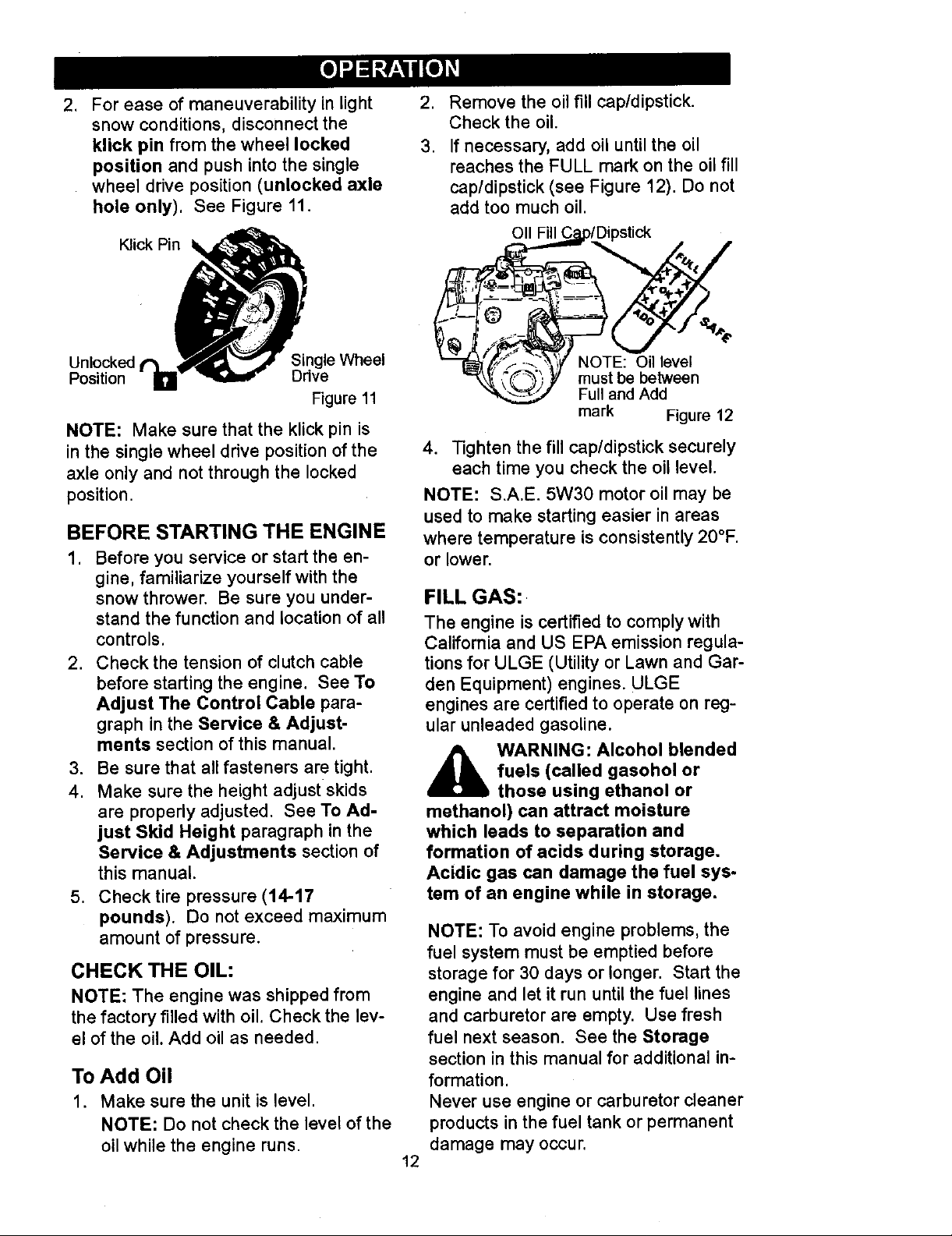
. For ease of maneuverability in light
snow conditions, disconnect the
kiick pin from the wheel locked
position and push into the single
wheel drive position (unlocked axle
hole only). See Figure 11.
Klick Pin
,
Remove the oil fill cap/dipstick.
Check the oil.
3.
If necessary, add oil until the oil
reaches the FULL mark on the oil fill
cap/dipstick (see Figure 12). Do not
add too much oil.
Oll Fill Cj_p/Dipstick
Unlocked ' Single Wheel
Position Drive
Figure 11
NOTE: Make sure that the klick pin is
in the single wheel drive position of the
axle only and not through the locked
position.
BEFORE STARTING THE ENGINE
.
Before you service or start the en-
gine, familiarize yourself with the
snow thrower. Be sure you under-
stand the function and location of all
controls.
2. Check the tension of clutch cable
before starting the engine. See To
Adjust The Control Cable para-
graph in the Service & Adjust-
ments section of this manual.
3. Be sure that all fasteners are tight.
4. Make sure the height adjust skids
are properly adjusted. See To Ad-
just Skid Height paragraph in the
Service & Adjustments section of
this manual.
5. Check tire pressure (14-17
pounds). Do not exceed maximum
amount of pressure.
CHECK THE OIL:
NOTE: The engine was shipped from
the factory filled with oil. Check the lev-
el of the oil. Add oil as needed.
TO Add Oil
1, Make sure the unit is level,
NOTE: Do not check the level of the
oil while the engine runs
"_'I_,'_"J----_.',_Y NOTE: Oil level
"_ _(_-_i Y must be between
Full and Add
mark Figure 12
4. Tighten the fill cap/dipstick securely
each time you check the oil level.
NOTE: S.A.E. 5W30 motor oil may be
used to make starting easier in areas
where temperature is consistently 20°F.
or lower.
FILL GAS:
The engine is certified to comply with
California and US EPA emission regula-
tions for ULGE (Utility or Lawn and Gar-
den Equipment) engines. ULGE
engines are certified to operate on reg-
ular unleaded gasoline.
,_ WARNING: Alcohol blended
methanol) can attract moisture
which leads to separation and
formation of acids during storage.
Acidic gas can damage the fuel sys-
tem of an engine while in storage.
NOTE: To avoid engine problems, the
fuel system must be emptied before
storage for 30 days or longer. Start the
engine and let it run until the fuel lines
and carburetor are empty. Use fresh
fuel next season. See the Storage
section in this manual for additional in-
formation.
Never use engine or carburetor cleaner
products in the fuel tank or permanent
damage may occur.
12
fuels (called gasohol or
those using ethanol or
Page 13
Fillthefuel tank onlywith a fresh,
clean, unleaded regular, unleaded pre-
mium, or reformulated automotive gas-
oline. DO NOT use leaded gasoline.
Make sure that the container you pour
the gasoline from is clean and free from
rust or other foreign particles. Never
use gasoline that may be stale from
long periods of storage in the container.
,_ WARNING: Gasoline is flam-
gasoline.
• Do not fill fuel tank while snow
• Keep away from open flame or an
• Neverfill the tank completely. Fill
• Always fill fuel tank outdoors and
• Make sure to wipe up any spilled
• Store gasoline in a clean, ap-
mable. Always use caution
when handling or storing
thrower is running, when it is hot,
or when snow thrower is in an en-
closed area.
electrical spark and do not smoke
while filling the fuel tank.
the tank to within 1/4"-1/2" from
the top to provide space for ex-
pansion of fuel.
use a funnel or spout to prevent
spilling.
fuel before stating the engine,
proved container and keep the
cap in place on the container.
_ ARNING: The starter is
designed to operate on 120 volt AC
household current. It must be prop-
erly grounded at all times to avoid
the possibility of electrical shock
which may be injurious to operator.
• Follow all instructions carefully
as set forth in the "To Start En-
• Determine that your house wiring
Ask a licensed electrician if you
are not sure. If your house wire
• If your system is grounded and a
three-hole receptacle is not avail-
able at the point your starter will
• When connecting 120 volt AC
equipped with a three-wire
power cord and plug and is
gine" section.
is a three-wira grounded system.
system is not a three-wire system,
do not use this electric starter un-
der any conditions.
normally be used, one should be
installed by a licensed electrician.
"Power Cord", always connect the
cord to the Switch Box on the en-
gine first, then plug the other end
into the three-hole grounded re-
ceptacle. When disconnecting
"Power Cord", always unplug the
end in the three-hole grounded re-
ceptacle first.
TO STOP ENGINE
To stop engine, move the throttle con-
trol lever to "STOP" position and re-
move key. Keep the key in a safe
place. The engine will not start without
the key.
TO START ENGINE
Be sure that the engine has sufficient
oil. The snow thrower engine is
equipped with a 120 volt A.C. electric
starter and recoil starter. Before start-
ing the engine, be certain that you have
read the following information.
How To Start A Cold Engine
1. Be sure auger drive and traction
drive levers are in the disengaged
(RELEASED) position.
2. Move throttle control to "FAST"
position.
3. Insert the ignition key into the igni-
tion slot. Make sure it snaps into
place. Do not turn key.
4. Rotate choke knob clockwise to the
choke ON position.
5. (Electric Start) Plug the power cord
into the switch box on the engine.
Plug the other end of power cord
into a three-hole, grounded 120
VOLT, AC receptacle.
13
Page 14
6. Pushthe primer button as speci-
fied below. Remove finger from
primer button between pushes.
• Do not push if temperature
above 50 ° F (10 ° C).
• Push two times if temperature is
50° F (10 ° C) to 15°F (-10 ° C).
• Push four times if temperature is
below 15 ° F (-10° C).
• Push five times if temperature is
below 0° F (-18 ° C).
7. (Electric Start) Push down on the
starter button until the engine
starts. Do not crank for more than
10 seconds at a time. This electric
starter is thermally protected. If
overheated it will stop automatically
and can be restarted only when it
has cooled to a safe temperature (a
wait of about 5 to 10 minutes is re-
quired).
8. (Recoil Start) Rapidly pull the re-
coil starter handle. Do not allow
the recoil starter handle to snap
back, Slowly return the recoil start-
er handle.
9. If the engine does not start in 5 or 6
tries, See Difficult Starting in the
"Troubleshooting Table".
10. When the engine starts, move the
choke control to "1/2 choke" posi-
tion. When engine runs smoothly,
move choke control to the off
Position.
11. (Electric Start) First disconnect
power cord from receptacle. Then,
disconnect the power cord from the
switch box.
12. Run engine at full throttle "FAST"
when throwing snow.
Allow the engine to warm up for several
minutes before blowing snow in temper-
atures below 0°F.
How To Start A Warm Engine
If restarting a warm engine after a short
shutdown, leave the choke lever in the
off position and do not push the primer
button. If the engine fails to start, follow
the Cold Start instructions.
FROZEN STARTER
If the starter is frozen and will not turn
engine:
1. Pull as much rope out of the starter
as possible.
2. Release the starter handle and let it
snap back against the starter. Re-
peat until the engine starts.
To help prevent possible freeze-up of
recoil starter and engine controls, pro-
ceed as follows after each snow remov-
al job.
1. With the engine running, pull the
starter rope hard with a continuous
full arm stroke three or four times.
Pulling of starter rope will produce a
loud clattering sound. This is not
harmful to the engine or starter.
2. With the engine not running, wipe all
snow and moisture from the carbu-
retor cover in area of control levers.
Also move throttle control, choke
control, and starter handle several
times.
,_ WARNING: Never run en-
gine exhaust contains CARBON
MONOXIDE, AN ODORLESS AND
DEADLY GAS. Keep hands, feet,
hair and loose clothing away from
any moving parts on engine and
snow thrower,
gine indoors or in enclosed,
poorly ventilated areas. En-
The temperature of muffler and
nearby areas may exceed 150°F.
Avoid these areas.
DO NOT allow children or young
teenagers to operate or be near
snow thrower while it is operat-
ing.
14
Page 15
TO REMOVE SNOW FROM AUGER
A ARNING: Do not attempt
• auger without taking the following
precautions:
A cleaning stick is attached to the top of
the auger housing. Use the cleaning
to remove snow or debris
that may become lodged in
stick to remove snow from the auger
housing.
• Release auger drive lever.
• Move throttle lever to stop position.
• Remove (do not turn) ignition key.
• Disconnect spark plug wire.
• Do not place your hands in the au-
ger or discharge chute. Use the
cleaning stick to remove snow.
SNOW THROWING TIPS
.
For maximum snow thrower efficien-
cy in removing snow, adjust ground
speed, NEVER the throttle. Go
slower in deep, freezing or wet
snow. If the wheels slips, reduce
forward speed. The engine is de-
signed to deliver maximum perfor-
mance at full throttle and should be
run at this power setting at all times.
,
Most efficient snow throwing is ac-
complished when the snow is re-
moved immediately after if falls.
,
For complete snow removal, slightly
overlap each path previously taken.
4.
The snow should be discharged
down wind whenever possible.
5.
For normal usage, set the skids so
that the scraper bar is 1/8" above
the skids. For extremely hard-
packed snow surfaces, adjust the
skids upward so that the scraper
bar touches the ground.
.
On gravel or crushed rock surfaces,
set the skids at 1-1/4" below the
scraper bar. See To Adjust Skid
Height paragraph in the Service &
Adjustments section of this manu-
al. Rocks and gravel must not be
picked up and thrown by the ma-
chine.
.
After the snow throwing job has
been completed, allow the engine to
idle for a few minutes, which will
melt snow and accumulated ice off
the engine.
.
Clean the snow thrower thoroughly
after each use.
9.
Remove ice and snow accumulation
and all debris from the entire snow
thrower, and flush with water (if pos-
sible) to remove all salt or other
chemicals. Wipe snow thrower dry.
15
Page 16
SERVICERECORDS
Fillindatesasyou Before Every Every Every
completeregular Each 5 10 25 Each Befe'e SERVICE
service. Use Often Hours Hours Hours Season Storage DATES
ChainLubrication _/
Change Engine Oil _"
RemoveFuel _/ _/
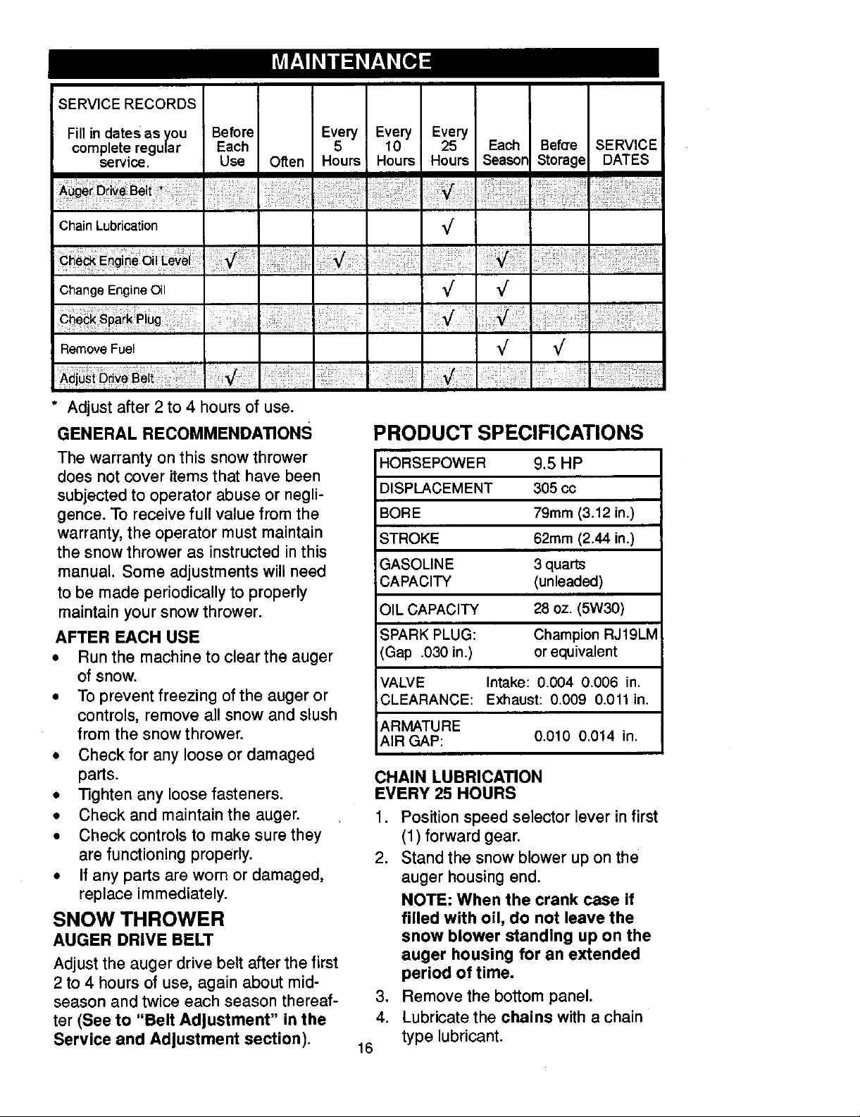
* Adjust after 2 to 4 hours of use,
GENERAL RECOMMENDATIONS
PRODUCT SPECIFICATIONS
The warranty on this snow thrower
does not cover items that have been
subjected to operator abuse or negli-
gence. To receive full value from the
warranty, the operator must maintain
the snow thrower as instructed in this
manual. Some adjustments will need
to be made periodically to properly
maintain your snow thrower.
AFTER EACH USE
• Run the machine to clear the auger
of snow.
• To prevent freezing of the auger or
controls, remove all snow and slush
from the snow thrower.
• Check for any loose or damaged
parts.
• Tighten any loose fasteners.
• Check and maintain the auger.
• Check controls to make sure they
are functioning properly.
• If any parts are worn or damaged,
replace immediately.
SNOW THROWER
AUGER DRIVE BELT
Adjust the auger drive belt after the first
2 to 4 hours of use, again about mid-
season and twice each season thereaf-
ter (See to "Belt Adjustment" in the
Service and Adjustment section).
HORSEPOWER
DISPLACEMENT
BORE
STROKE
GASOLINE
CAPACITY
OIL CAPACITY
SPARK PLUG:
(Gap .030 in.)
VALVE Intake: 0.004 0.006 in.
CLEARANCE: Exhaust: 0.009 0.011 in.
ARMATURE
AIR GAP: 0.010 0.014 in.
9.5 HP
305 cc
79mm (3.12 in.)
62mm (2.44 in.)
3 quarts
(unleaded)
28 oz. (5W30)
Champion RJ19LM
or equivalent
CHAIN LUBRICATION
EVERY 25 HOURS
1. Position speed selector lever in first
(1) forward gear.
2. Stand the snow blower up on the
auger housing end.
NOTE: When the crank case If
filled with oil, do not leave the
snow blower standing up on the
auger housing for an extended
period of time.
3, Remove the bottom panel.
4. Lubricate the chains with a chain
16
type lubricant.
Page 17
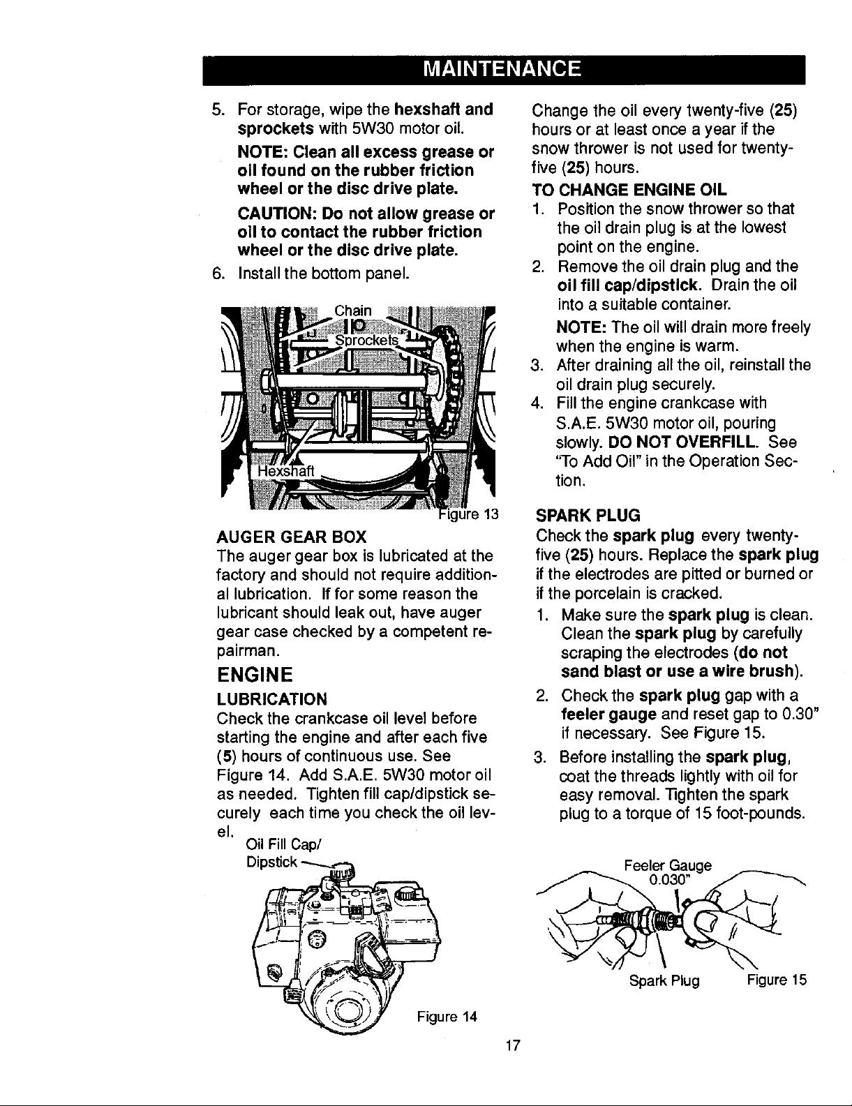
,
For storage, wipe the hexshaft and
sprockets with 5W30 motor oil
NOTE: Clean all excess grease or
oll found on the rubber friction
wheel or the disc drive plate.
CAUTION: Do not allow grease or
oil to contact the rubber friction
wheel or the disc drive plate,
6. Install the bottom panel.
Chain
Change the oil every twenty-five (25)
hours or at least once a year if the
snow thrower is not used for twenty-
five (25) hours.
TO CHANGE ENGINE OIL
1. Position the snow thrower so that
the oil drain plug is at the lowest
point on the engine.
2. Remove the oil drain plug and the
oil fill cap/dipstick. Drain the oil
into a suitable container.
NOTE: The oil will drain more freely
when the engine is warm.
.
After draining all the oil, reinstall the
oil drain plug securely.
4.
Fill the engine crankcase with
S.A.E. 5W30 motor oil, pouring
slowly. DO NOT OVERFILL. See
'qo Add Oil" in the Operation Sec-
tion.
AUGER GEAR BOX
The auger gear box is lubricated at the
factory and should not require addition-
al lubrication. If for some reason the
lubricant should leak out, have auger
gear case checked by a competent re-
pairman.
ENGINE
LUBRICATION
Check the crankcase oil level before
starting the engine and after each five
(5) hours of continuous use. See
Figure 14. Add S.A.E. 5W30 motor oil
as needed. Tighten fill cap/dipstick se-
curely each time you check the oil lev-
el.
Oil Fill Cap/
D
13
SPARK PLUG
Check the spark plug every twenty-
five (25) hours. Replace the spark plug
ifthe electrodes are pitted or burned or
ifthe porcelain is cracked.
1. Make sure the spark plug is clean.
Clean the spark plug by carefully
scraping the electrodes (do not
sand blast or use a wire brush).
2. Check the spark plug gap with a
feeler gauge and reset gap to 0.30"
if necessary. See Figure 15.
.
Before installing the spark plug,
coat the threads lightly with oil for
easy removal. 13ghten the spark
plug to a torque of 15 foot-pounds.
Feeler Gauge
Figure 14
Spark Plug Figure 15
17
Page 18
,_ WARNING: Always discon-
make contact with spark plug to pre-
vent accidental starting when mak-
ing any adjustments or repairs.
nect the spark plug wire and
place it where it cannot
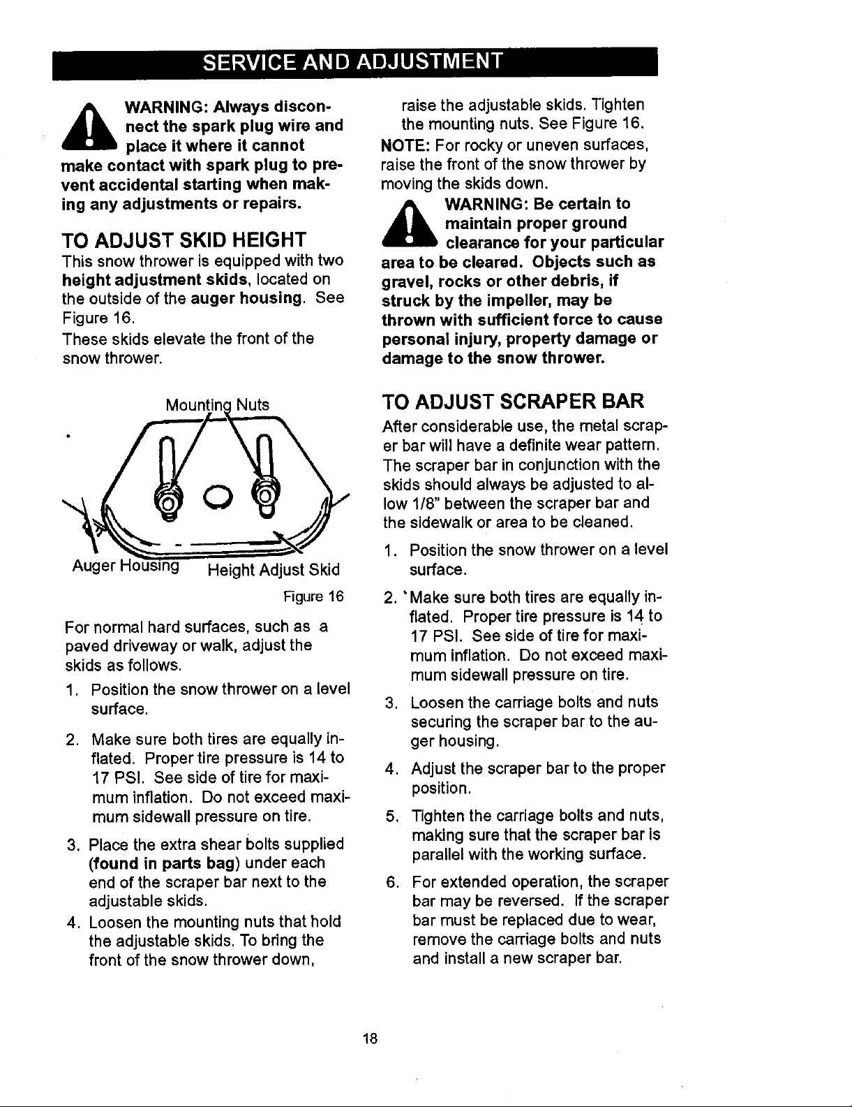
TO ADJUST SKID HEIGHT
This snow thrower is equipped with two
height adjustment skids, located on
the outside of the auger housing. See
Figure 16.
These skids elevate the front of the
snow thrower.
raise the adjustable skids. Tighten
the mounting nuts. See Figure 16.
NOTE: For rocky or uneven surfaces,
raise the front of the snow thrower by
moving the skids down.
,_ WARNING: Be certain to
area to be cleared. Objects such as
gravel, rocks or other debris, if
struck by the impeller, may be
thrown with sufficient force to cause
personal injury, property damage or
damage to the snow thrower.
maintain proper ground
clearance for your particular
Mountin Nuts
,, O
Auger _g Height Adjust Skid
Figure 16
For normal hard surfaces, such as a
paved driveway or walk, adjust the
skids as follows.
1. Position the snow thrower on a level
surface.
2. Make sure both tires are equally in-
flated. Proper tire pressure is 14 to
17 PSI. See side of tire for maxi-
mum inflation. Do not exceed maxi-
mum sidewall pressure on tire.
3, Place the extra shear bolts supplied
(found in parts bag) under each
end of the scraper bar next to the
adjustable skids.
4. Loosen the mounting nuts that hold
the adjustable skids. To bring the
front of the snow thrower down,
TO ADJUST SCRAPER BAR
After considerable use, the metal scrap-
er bar will have a definite wear pattern.
The scraper bar in conjunction with the
skids should always be adjusted to al-
low 1/8" between the scraper bar and
the sidewalk or area to be cleaned.
1. Position the snow thrower on a level
surface.
2. ' Make sure both tires are equally in-
flated. Proper tire pressure is 14 to
17 PSI. See side of tire for maxi-
mum inflation. Do not exceed maxi-
mum sidewall pressure on tire.
3. Loosen the carriage bolts and nuts
securing the scraper bar to the au-
ger housing.
4. Adjust the scraper bar to the proper
position.
5. Tighten the carriage bolts and nuts,
making sure that the scraper bar is
parallel with the working surface.
.
For extended operation, the scraper
bar may be reversed. If the scraper
bar must be replaced due to wear,
remove the carriage bolts and nuts
and install a new scraper bar.
18
Page 19
BELT ADJUSTMENT
Traction Drive Belt
The traction drive belt has constant
spring pressure and does not require
an adjustment. If the traction drive belt
is slipping, replace the belt. See "How
To Replace The Belts" in the Service
And Adjustment section.
Auger Drive Belt
If your snow blower will not discharge
snow. check the control cable adjust-
ment. If it is correct, then check the
condition of the auger drive belt. If it is
damaged or loose, replace it (see "How
To Replace The Belts" in this section of
the manual).
1. Disconnect spark plug wire.
,
Have someone engage auger drive
clutch. Check tension on belt (op-
posite idler pulley). Belt should de-
flect about 1/2 inch (12.5 mm) with
moderate pressure (Figure 18). You
may have to move idler pulley more
than once to obtain the correct ten-
sion.
Auger
L Drive
/ _ Engine
"A Po,ey
J ;4 ° 1/2 inch
t ",,___ (12.5mm)
Idler_......,.([ t.f',,_, ''''_ Deflection
Pulley 1 " ',,_
Engaged /,_ ",_
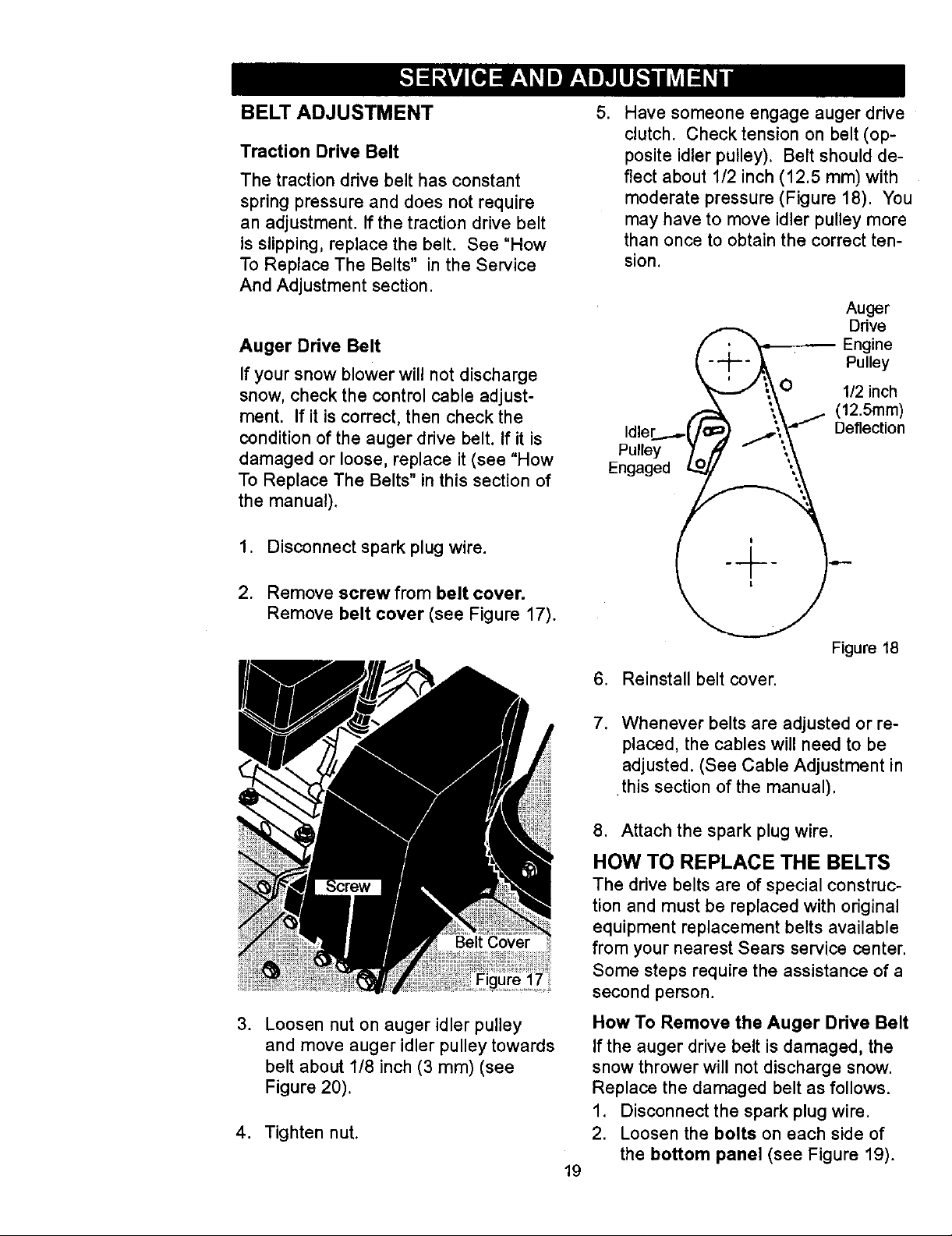
2. Remove screw from belt cover.
Remove belt cover (see Figure 17).
.
Loosen nut on auger idler pulley
and move auger idler pulley towards
belt about 1/8 inch (3 mm) (see
Figure 20).
4. Tighten nut.
17
Figure 18
6. Reinstall belt cover.
7. Whenever belts are adjusted or re-
placed, the cables will need to be
adjusted. (See Cable Adjustment in
this section of the manual).
8. Attach the spark plug wire.
HOW TO REPLACE THE BELTS
The drive belts are of special construc-
tion and must be replaced with original
equipment replacement belts available
from your nearest Sears service center.
Some steps require the assistance of a
second person.
How To Remove the Auger Drive Belt
If the auger drive belt is damaged, the
snow thrower will not discharge snow.
Replace the damaged belt as follows.
1. Disconnect the spark plug wire.
2. Loosen the bolts on each side of
the bottom panel (see Figure 19).
19
Page 20
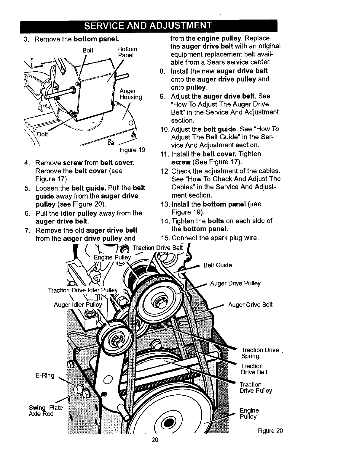
3, Remove the bottom panel.
Bolt Bottom
_,'_"_(_ _/'Auger
Figure 19
4. Remove screw from belt cover.
Remove the belt cover (see
Figure 17).
5. Loosen the belt guide. Pull the belt
guide away from the auger drive
pulley (see Figure 20).
6. Pull the idler pulley away from the
auger drive belt.
7. Remove the old auger drive belt
from the auger drive pulley and
from the engine pulley. Replace
the auger drive belt with an original
equipment replacement belt avail-
able from a Sears service center.
8. Install the new auger drive belt
onto the auger drive pulley and
onto pulley,
9, Adjust the auger drive belt. See
"How To Adjust The Auger Drive
Belt" in the Service And Adjustment
section.
10. Adjust the belt guide. See "How To
Adjust The Belt Guide" in the Ser-
vice And Adjustment section.
11, Install the belt cover. Tighten
screw (See Figure 17).
12. Check the adjustment of the cables.
See "How To Check And Adjust The
Cables" in the Service And Adjust-
ment section.
13. Install the bottom panel (see
Figure 19),
14. Tighten the bolts on each Side of
the bottom panel.
15. Connect the spark plug wire.
Traction Drive Idler Pulley
Auger Idler Pulley
E-Ring
Swing Plate
Axle Rod
t '_'_")'_ Traction Drive Belt-
Engine Pulley i
Belt Guide
Auger Drive Pulley
\
Auger Drive Belt
Traction Drive.
Spring
Traction
Drive Belt
Traction
Drive Pulley
Pulley
Engine
Figure 20
20
Page 21
How To Remove
The Traction Drive Belt
If the snow thrower will not move for-
ward, check the traction drive belt for
wear or damage. If the traction drive
belt is worn or damaged, replace the
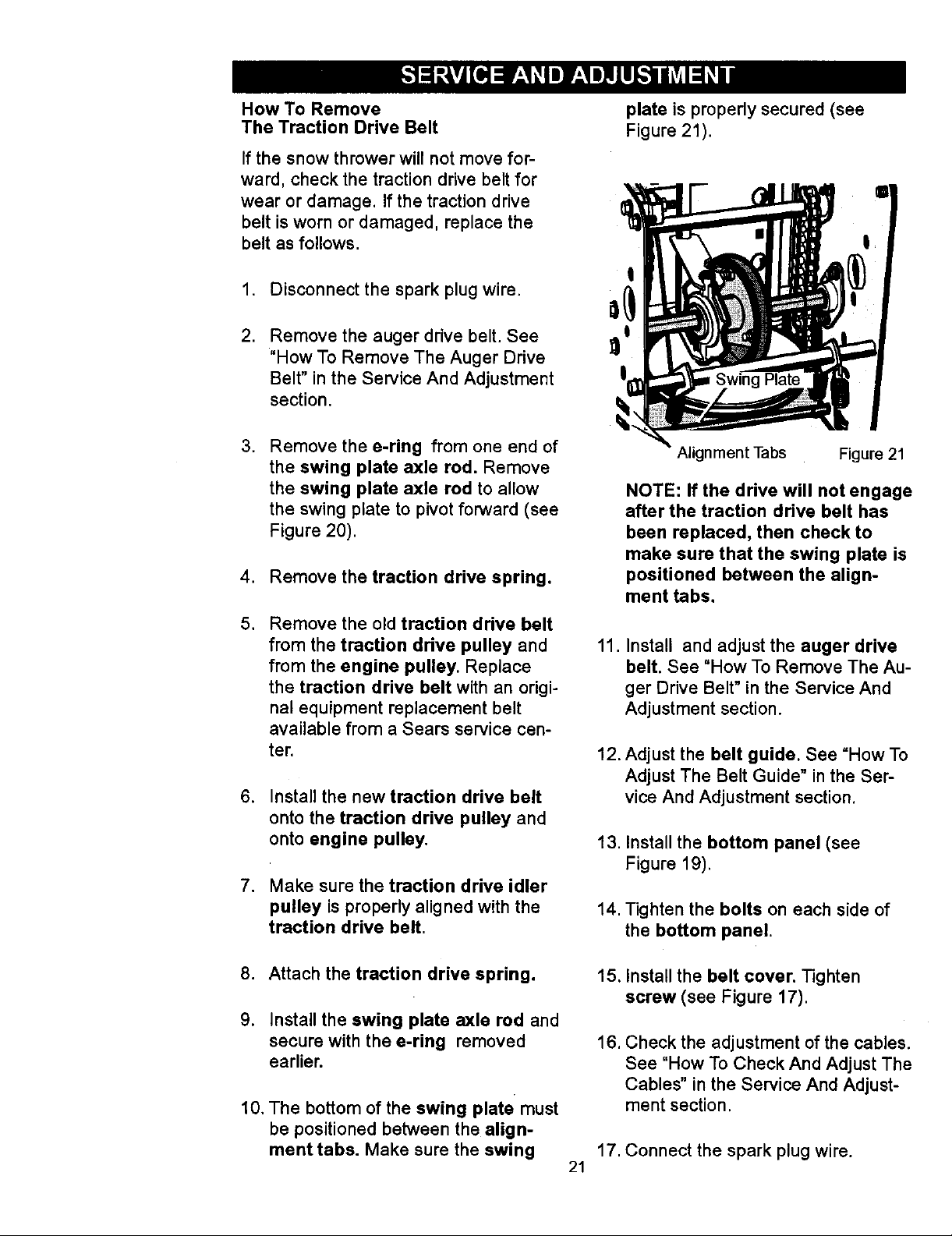
belt as follows.
plate is propedy secured (see
Figure 21).
,
Disconnect the spark plug wire.
2.
Remove the auger drive belt. See
"How To Remove The Auger Drive
Belt" in the Service And Adjustment
section.
.
Remove the e.ring from one end of
the swing plate axle rod. Remove
the swing plate axle rod to allow
the swing plate to pivot forward (see
Figure 20).
4. Remove the traction drive spring.
. Remove the old traction drive belt
from the traction drive pulley and
from the engine pulley. Replace
the traction drive belt with an origi-
nal equipment replacement belt
available from a Sears service cen-
ter.
6. Install the new traction drive belt
onto the traction drive pulley and
onto engine pulley.
7. Make sure the traction drive idler
pulley is properly aligned with the
traction drive belt.
!
Alignment Tabs Figure 21
NOTE: If the drive will not engage
after the traction drive belt has
been replaced, then check to
make sure that the swing plate is
positioned between the align-
ment tabs.
11.
Install and adjust the auger drive
belt. See "How To Remove The Au-
ger Drive Belt" in the Service And
Adjustment section.
12. Adjust the belt guide. See =How To
Adjust The Belt Guide" in the Ser-
vice And Adjustment section.
13. Install the bottom panel (see
Figure 19).
14. Tighten the bolts on each side of
the bottom panel.
8. Attach the traction drive spring.
9. Install the swing plate axle rod and
secure with the e-ring removed
earlier.
10. The bottom of the swing plate must
be positioned between the align-
ment tabs. Make sure the swing
15. Install the belt cover. Tighten
screw (see Figure 17).
16. Check the adjustment of the cables.
See "How To Check And Adjust The
Cables" in the Service And Adjust-
ment section.
17. Connect the spark plug wire.
21
Page 22
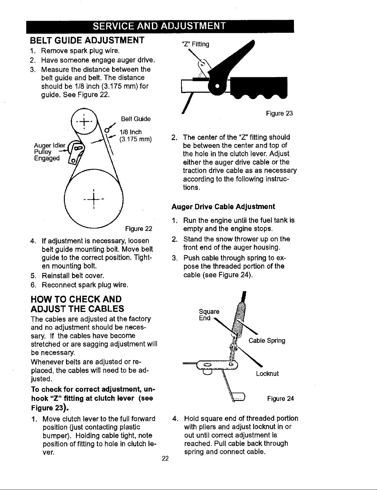
BELT GUIDE ADJUSTMENT
1. Remove spark plug wire.
2. Have someone engage auger drive.
3. Measure the distance between the
belt guide and belt. The distance
should be 1/8 inch (3.175 ram)for
guide. See Figure 22.
"Z" Fitting
Belt Guide
f
1/8Inch
Auger Idler I_
"" (3.175 rnm)
Pulley
Engaged
Figure 22
4. If adjustment is necessary, loosen
belt guide mounting bolt. Move belt
guide to the correct position. Tight-
en mounting bolt.
5. Reinstall belt cover.
6. Reconnect spark plug wire.
Figure 23
2. The canter of the "Z" fitting should
be between the center and top of
the hole in the clutch lever. Adjust
either the auger drive cable or the
traction drive cable as as necessary
according to the following instruc-
tions.
Auger Drive Cable Adjustment
1. Run the engine until the fuel tank is
empty and the engine stops.
2. Stand the snow thrower up on the
front end of the auger housing.
3. Push cable through spring to ex-
pose the threaded portion of the
cable (see Figure 24).
HOW TO CHECK AND
ADJUST THE CABLES
The cables are adjusted at the factory
and no adjustment should be neces-
sary. If the cables have become
stretched or are sagging adjustment will
be necessary.
Whenever belts are adjusted or re-
placed, the cables will need to be ad-
justed.
To check for correct adjustment, un-
hook "Z" fitting at clutch lever (see
Figure 23).
1. Move clutch lever to the full forward
position (just contacting plastic
bumper). Holding cable tight, note
position of fitting to hole in clutch le-
ver.
22
Square
Cable Spring
O
Locknut
Figure 24
,
Hold square end of threaded portion
with pliers and adjust Iocknut in or
out until correct adjustment is
reached. Pull cable back through
spring and connect cable.
Page 23
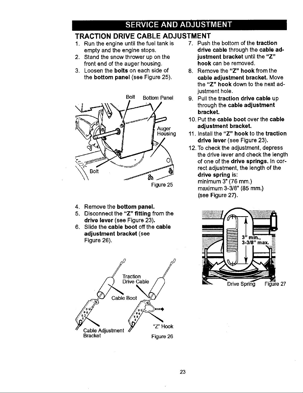
TRACTION DRIVE CABLE ADJUSTMENT
1. Run the engine until the fuel tank is
empty and the engine stops.
2. Stand the snow thrower up on the
front end of the auger housing.
3. Loosen the bolts on each side of
the bottom panel (see Figure 25).
Bolt Bottom Panel
\
Housing
\_ Bolt
Figure 25
7. Push the bottom of the traction
drive cable through the cable ad-
justment bracket until the "Z"
hook can be removed.
8. Remove the "Z" hook from the
cable adjustment bracket. Move
the "Z" hook down to the next ad-
justment hole.
9. Pull the traction drive cable up
through the cable adjustment
bracket.
10. Put the cable boot over the cable
adjustment bracket.
11. Install the "Z" hook to the traction
drive lever (see Figure 23).
12. To check the adjustment, depress
the drive lever and check the length
of one of the drive springs. In cor-
rect adjustment, the length of the
drive spring is:
minimum 3" (76 ram.)
maximum 3-3/8" (85 mm.)
(see Figure 27).
4. Remove the bottom panel.
5. Disconnect the "Z" fitting from the
drive lever (see Figure 23).
6. Slide the cable boot off the cable
adjustment bracket (see
Figure 26).
Traction /
DriveCable////
Cable Adjustment /_ "Z" Hook
Bracket Figure 26
Drive Spring Figure 27
23
Page 24
HOW TO ADJUST OR REPLACE
THE FRICTION WHEEL
How To Check The Friction Wheel
If the snow thrower will not move for-
ward, check the traction drive belt, the
traction drive cable or the friction wheel.
If the friction wheel is worn or damaged,
it must be replaced. See "How To Re-
p|ace the Friction Wheel" in this section.
If the friction wheel is not worn or dam-
aged, check as follows.
1. Run the engine until the fuel tank is
empty and the engine stops.
2. Stand the snow thrower up on the
front end of the auger housing
(see Figure 28).
3. Disconnect the spark plug wire.
4. Loosen the bolts on each side of
the bottom panel (see Figure 28).
5. Install the bottom panel (see
Figure 28).
6. Tighten the bolts on each side of
the bottom panel.
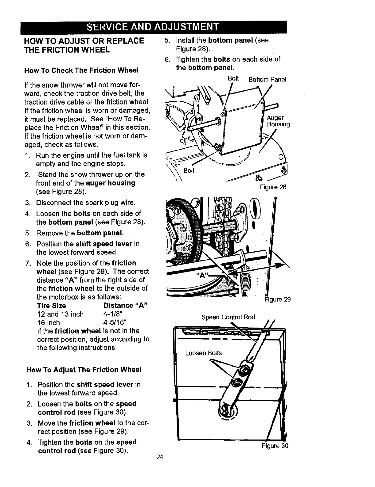
Bolt Bottom Panel
i___,,2er
_. Housing
Figure 28
5. Remove the bottom panel.
6. Position the shift speed lever in
the lowest forward speed.
7. Note the position of the friction
wheel (see Figure 29). The correct
distance "A" from the right side of
the friction wheel to the outside of
the motorbox is as follows:
Tire Size Distance "A"
12 and 13 inch 4-1/8"
16 inch 4-5/16"
If the friction wheel is not in the
correct position, adjust according to
the following instructions.
How To Adjust The Friction Wheel
1. Position the shift speed lever in
the lowest forward speed.
2. Loosen the bolts on the speed
control rod (see Figure 30).
3. Move the friction wheel to the cor-
rect position (see Figure 29).
4. Tighten the bolts on the speed
control rod (see Figure 30).
Figure 29
Speed Control Rod
Figure 30
24
Page 25
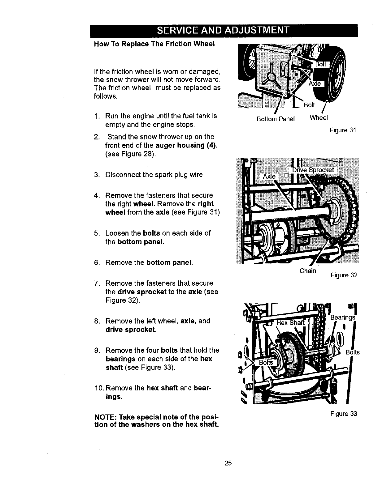
How To Replace The Friction Wheel
If the friction wheel is worn or damaged,
the snow thrower will not move forward.
The friction wheel must be replaced as
follows.
.
Run the engine until the fuel tank is
empty and the engine stops.
2.
Stand the snow thrower up on the
front end of the auger housing (4).
(see Figure 28).
3. Disconnect the spark plug wire.
4. Remove the fasteners that secure
the right wheel. Remove the right
wheel from the axle (see Figure 31)
Bottom Panel
Bolt
Wheel
Figure 31
5. Loosen the bolts on each side of
the bottom panel.
.
Remove the bottom panel.
7.
Remove the fasteners that secure
the drive sprocket to the axle (see
Figure 32).
.
Remove the left wheel, axle, and
drive sprocket.
,
Remove the four bolts that hold the
bearings on each side of the hex
shaft (see Figure 33).
10. Remove the hex shaft and bear-
ings.
Chain
Figure 32
=!
Bolts
NOTE: Take special note of the posi-
tion of the washers on the hex shaft.
Figure 33
25
Page 26
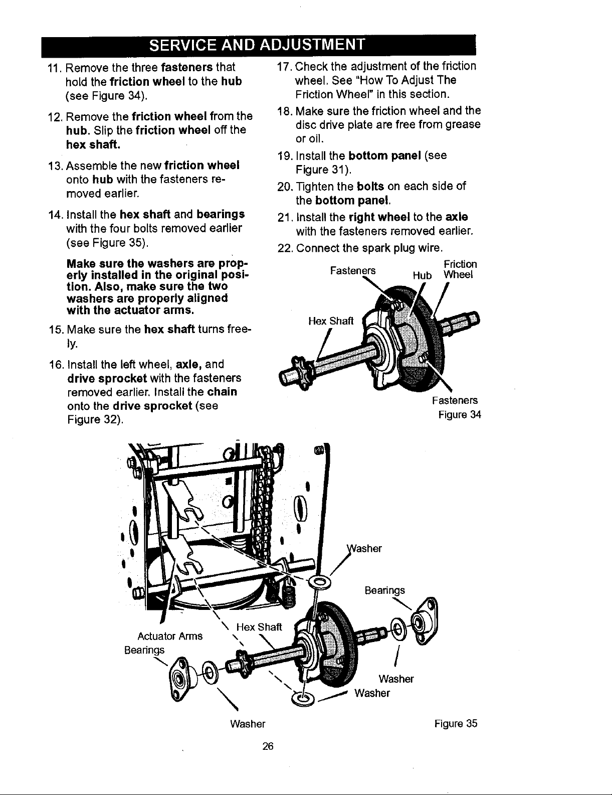
11. Remove the three fasteners that
hold the friction wheel to the hub
(see Figure 34).
12. Remove the friction wheel from the
hub. Slip the friction wheel off the
hex shaft.
131Assemble the new friction wheel
onto hub with the fasteners re-
moved earlier.
14. Install the hex shaft and bearings
with the four bolts removed earlier
(see Figure 35).
Make sure the washers are prop-
erly installed in the original posi-
tion. Also, make sure the two
washers are properly aligned
with the actuator arms.
15. Make sure the hex shaft turns free-
ly.
17. Check the adjustment of the friction
wheel. See "How To Adjust The
Friction Wheel" in this section.
18. Make sure the friction wheel and the
disc drive plate are free from grease
or oil.
19. Install the bottom panel (see
Figure 31).
20. Tighten the bolts on each side of
the bottom panel.
21. Install the right wheel to the axle
with the fasteners removed earlier.
22. Connect the spark plug wire.
Fasteners
Hub Wheel
Hex Shaft
Friction
16. Install the left wheel, axle, and
drive sprocket with the fasteners
removed earlier. Install the chain
onto the drive sprocket (see
Figure 32).
Actuator Arms
Beadngs
Fasteners
Figure 34
!
asher
Bearings
/
Washer
Washer
/ Washer
Figure 35
26
Page 27
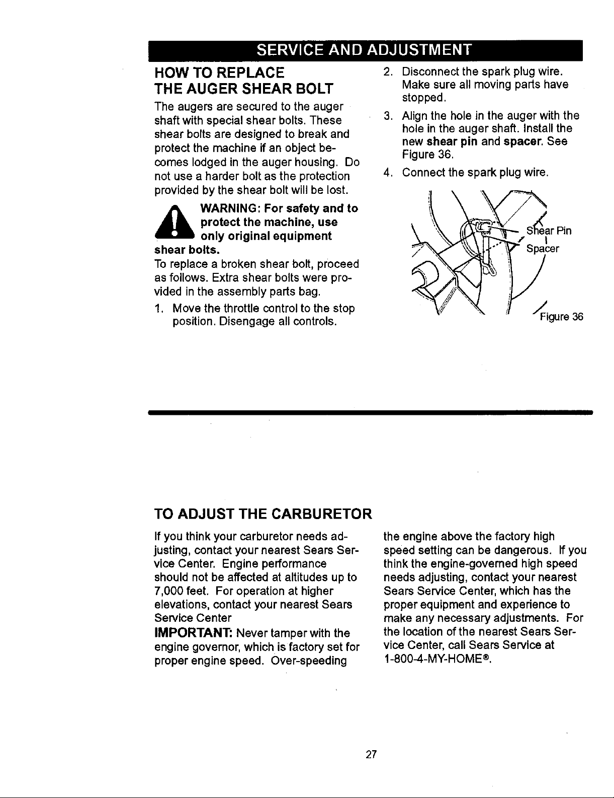
HOW TO REPLACE
THE AUGER SHEAR BOLT
The augers are secured to the auger
shaft with special shear bolts. These
shear bolts are designed to break and
protect the machine if an object be-
comes lodged in the auger housing. Do
not use a harder bolt as the protection
provided by the shear bolt will be lost.
2. Disconnect the spark plug wire.
Make sure all moving parts have
stopped.
3. Align the hole in the auger with the
hole in the auger shaft. Install the
new shear pin and spacer. See
Figure 36.
4. Connect the spark plug wire.
,_ WARNING: For safety and to
shear bolts.
To replace a broken shear bolt, proceed
as follows. Extra shear bolts were pro-
vided in the assembly parts bag.
1. Move the throttle control to the stop
protect the machine, use
only original equipment
position. Disengage all controls.
arPn
__ J"/" _Figure 36
TO ADJUST THE CARBURETOR
If you think your carburetor needs ad-
justing, contact your nearest Sears Ser-
vice Center. Engine performance
should not be affected at altitudes up to
7,000 feet. For operation at higher
elevations, contact your nearest Sears
Service Center
IMPORTANT: Never tamper with the
engine governor, which is factory set for
proper engine speed. Over-speeding
the engine above the factory high
speed setting can be dangerous. If you
think the engine-governed high speed
needs adjusting, contact your nearest
Sears Service Center, which has the
proper equipment and experience to
make any necessary adjustments. For
the location of the nearest Sears Ser-
vice Center, call Sears Service at
1-800-4-MY-HOME ®.
27
Page 28

_ ARNING: Never store your
lated area. If gasoline remains in the
tank, fumes may reach an open
flame, spark or pilot light from a fur-
nace, water heater, clothes dryer,
cigarette, etc.
To prevent damage (if snow thrower is
not used for more than 30 days) follow
the steps below.
snow thrower indoors or in
an enclosed, poorly venti-
SNOW THROWER
1. Thoroughly clean the snow thrower.
2. Lubricate all lubrication points. See
the Maintenance section.
3. Be sure that all nuts, bolts and
screws are securely fastened. In-
spect all visible moving parts for
damage, breakage and wear. Re-
place if necessary.
4. Touch up all rusted or chipped paint
surfaces; sand lightly before paint-
ing.
5. Cover the bare metal parts of the
blower housing auger and the im-
peller with rust preventative, such
as a spray lubricant.
NOTE: A yearly checkup or tune-up by
a Sears service center is a good way of
ensuring that your snow thrower will
provide maximum performance for the
next season.
ENGINE
Gasoline must be removed or treated to
prevent gum deposits from forming in
the fuel tank, filter, hose, and carburetor
during storage. Also, during storage al-
cohol blended gasoline that uses etha-
nol or methanol (sometimes called
gasohol) attracts water. It acts on the
gasoline to form acids which damage
the engine.
1. Run the engine until the fuel tank is
empty and the engine stops.
2. If you do not remove the gasoline,
use fuel stabilizer supplied with unit
or purchase Craftsman Fuel Stabi-
lizer No. 3550. Add fuel stabilizer to
any gasoline left in the tank to mini-
mize gum deposits and acids. If the
fuel tank is almost empty, mix stabi-
lizer with fresh gasoline in a sepa-
rate container and add some to the
fuel tank.
3. Always follow the instructions on the
stabilizer container. After the stabi-
lizer is added to the fuel tank, run
the engine at least ten minutes to
allow the mixture to reach the car-
buretor.
4. Change the engine oi!.
5. Lubricate the piston/cylinder area.
First, remove the spark plug and
squirt a few drops of clean engine
oil into the spark plug hole. Next,
cover the spark plug hole with a rag
to absorb oil spray. Then, pull two or
three times on the recoil starter rope
to rotate the engine. Finally, install
the spark plug and attach the spark
plug wire.
OTHER
1. If possible, store your snow thrower
indoors and cover itto give protec-
tion from dust and dirt.
2. If the snow thrower must be stored
outdoors, put the snow thrower on
blocks to raise it off of the ground.
3. Cover the snow thrower with a suit-
able protective cover that does not
retain moisture. Do not use plastic.
IMPORTANT: Never cover snow
thrower while engine and exhaust areas
are still warm.
28
Page 29

TROUBLE CORRECTION
CAUSE
Difficult starting Replace spark plug.
Engine runs erratically Blocked fuel line, empty gas Clean fuel line; check fuel
Engine stalls Unit running on CHOKE. !Set choke lever to OFF
Engine runs erratic; Remove fuel from fuel tank.
Loss of power Add fresh fuel.
Excessive vibration
Unit fails to propel itself
Defective spark plug.
Water or dirt in fuel system.
tank, or stale gasoline supply; add fresh gasoline
Water or dirt in fuel system.
Loose parts: damaged
impeller
Traction drive belt loose or
damaged.
Remove fuel from fuel tank.
Add fresh fuel.
;position.
Immediately stop engine.
Remove ignition key. Tighten
all fasteners and make all
lecessary repairs. If
vibration continues, take the
unit to a Sears service
center.
l Replace traction drive belt.
Unit fails to discharge
snow
Incorrect adjustment of
traction drive cable
Worn or damaged friction
wheel,
Auger drive belt loose or
damaged.
Auger control cable not
adjusted correctly.
Shear bolt broken
Discharge chute clogged.
, Foreign object lodged in Stop engine immediately and
auger disconnect spark plug wire.
Adjust traction drive cable.
Replace friction wheel.
Adjust auger drive belt;
replace if damaged.
Adjust auger control cable.
Replace shear bolt
Stop engine immediately and
disconnect spark plug wire.
Clean discharge chute and
inside of auger housing.
Remove object from auger.
29
Page 30

SEARS, ROEBUCK AND CO.
Federal and California Emission Control Systems LimitedWarranty
Small Off-Road Engines
CALIFORNIA & US EPA EMISSION
CONTROL WARRANTY STATEMENT
The U. S. Environmental Protection Agency
("EPA"), the California Air Resources Board
("CARB") and Seam, Roebuck and Co. are
pleased to explain the Federal and California
Emission Control Systems Warranty on your
new small off-road engine. In California, new
1995 and later small off-road engines must be
designed, built and equipped to meet the
State's stringent anti-smog standards. In oth-
er states, new 1997 and later model year en-
gines must be designed, built and equipped, at
the time of sale, to meet the U.S. EPA regula-
tions for small non-road engines. Seam, Roe-
buck and Co. will warrant the emission control
system on your small off-road engine for the
periods of time listed below, provided there
has been no abuse, neglect, unapproved mod-
ification, or improper maintenance of your
small off-road engine.
Your emission control system may include
parts such as the carburetor, ignition system
and exhaust system. Also included may be the
compression release system and other emis-
sion-related assemblies.
Where a warrantable condition exists, Seam,
Roebuck and Co. will repair your small off-
road engine at no cost to you for diagnosis,
parts and labor.
MANUFACTURER'S EMISSION
CONTROL SYSTEM WARRANTY
COVERAGE
Emission control systems on 1995 and later
model year California small off-road engines
are warranted for two years as hereinalter
noted. In other states, 1997 and later model
year engines are also warranted for two years.
If, during such warranty period, any emission-
related part on your engine is defective in ma-
terials or workmanship, the part will be
repaired or replaced by Sears, Roebuck and
Co.
quired maintenance listed in your Owner's
Manual, but Sears, Roebuck and Co. will not
deny warranty solely due to the lack of receipts
or for your failure to provide written evidence
of the performance of all scheduled mainte-
nance.
As the small off-road engine owner, you
should, however, be aware that Sears, Roe-
buck and Co. may deny you warranty cover-
age if your small off-road engine or a part
thereof has failed due to abuse, neglect, im-
proper maintenance or unapproved modifica-
tions.
You are responsible for presenting your small
off-road engine to a Sears, Roebuck and Co.
Authorized Service Outlet as soon as a prob-
lem exists. The warranty repairs should be
completed in a reasonable amount of time, not
to exceed 30 days.
Warranty service can be arranged by contact-
ing either a Seam, Roebuck and Co. Autho-
rized Service Outlet, or by contacting Seam,
Roebuck and Co. at 1-800-473-7247.
IMPORTANT NOTE
This warranty statement explains your rights
and obligations under the Emission Control
System Warranty "(ECS Warranty") which is
provided to you by Sears, Roebuck and Co.
pursuant to Califomia law. See also the Seam,
Roebuck and Co. Limited Warranties for
Seam, Roebuck and Co. which is enclosed
therewith on a separate sheet and also is pro-
vided to you by Sears, Roebuck and Co. The
ECS Warranty applies only to the emission
control system of your new engine. To the ex-
tent that there is any conflict in terms between
the ECS Wairanty and the Seam, Roebuck
and Co. Warranty, the ECS Warranty shall ap-
ply except in any circumstances in which the
Seam, Roebuck and Co. Warranty may pro-
vide a longer warranty period. Both the ECS
Warranty and the Sears, Roebuck and Co.
Warranty describe important rights and obliga-
tions with respect to your new engine.
OWNER'S WARRANTY
RESPONSIBILITIES
As the small off-road engine owner, you are
responsible for the performance of the re-
Warranty service can only be performed by a
Seam, Roebuck and Co. Authorized Service
Outlet. At the time of requesting warranty ser-
vice, evidence must be presented of the date
of sale to the odginal purchaser. The purchas-
3O
Page 31

ershallpayanychargesformakingservice
callsand/orfor transportingthe productsto
andfromtheplacewheretheinspection and/
or warranty work is performed. The purchaser
shall be responsible for any damage or loss in-
curred in connection with the transportation of
any engine or any part(s) thereof submitted for
inspection and/or warranty work.
If you have any questions regarding your war-
ranty rights and responsibilities, you should
contact Sears, Roebuck and Co. at
1-800-473-7247.
EMISSION CONTROL SYSTEM
WARRANTY
Emission Control System Warranty ("ECS
Warranty") for 1995 and later model year Cali-
fornia small off-rcad engines (for other states,
1997 and later model year engines):
A. APPLICABILITY: This warranty shall apply
to 1995 and later model year California small
off-road engines (for other states, 1997 and
later model year engines). The ECS Warranty
Period shall begin on the date the new engine
or equipment is delivered to its original, end-
use purchaser, and shall continue for 24 con-
secutive months thereafter.
B. GENERAL EMISSIONS WARRANTY
COVERAGE: Sears, Roebuck and Co. war-
rants to the original, end-use purchaser of the
new engine or equipment and to each subse-
quent purchaser that each of its small off-read
engines is:
1. Designed, built and equipped so as to con-
form with all applicable regulations adopted by
the Air Resources Board pursuant to its au-
thority in Chapters 1 and 2, Part 5, Division 26
of the Health and Safety Code, and
2. Free from defects in materials and work-
manship which, at any time during the ECS
Warranty Period, will cause a warranted emis-
sions-related part to fail to be identical in all
material respects to the part as described in
the engine manufacturer's application for certi-
fication.
C. The ECS Warranty only pertains to emis-
sions-related parts on your engine, as follows:
1. Any warranted, emissions-related parts
which are not scheduled for replacement as
required maintenance in the Owner's Manual
shall be warranted for the ECS Warranty Peri-
od. If any such part fails during the ECS War-
ranty Period, it shall be repaired or replaced by
Sears, Roebuck and Co. according to Subsec-
tion 4 below. Any such part repaired or re-
placed under the ECS Warranty shall be
warranted for any remainder of the ECS War-
ranty Period.
2. Any warranted, emissions-related part
which is scheduled only for regular inspection
as specified in the Owner's Manual shall be
warranted for the ECS Warranty Period. A
statement in such written instructions to the ef-
fect of "repair or replace as necessary", shall
not reduce the ECS Warranty Pedod. Any
such part repaired or replaced under the ECS
Warranty shall be warranted for the remainder
of the ECS Warranty Period.
3. Any warranted, emissions-related part
which is scheduled for replacement as re-
quired maintenance in the Owner's Manual,
shall be warranted for the period of time prior
to the first scheduled replacement point for
that part. If _he part fails prior to the first sched-
utad replacement, the part shall be repaired or
replaced by Sears, Roebuck and Co. accord-
ing to Subsection 4 below. Any such emis-
sions-related part repaired or replaced under
the ECS Warranty, shall be warranted for the
remainder of the ECS Warranty Period prior to
the first scheduled replacement point for such
emissions-related part.
4. Repair or replacement of any warranted,
emissions-related part under this ECS War-
ranty shall be performed at no charge to the
owner at a Sears, Roebuck and Co. Autho-
rized Service Outlet.
5. The owner shall not be charged for diagnos-
tic labor which leads to the determination that
a part covered by the ECS Warranty is in fact
defective, provided that such diagnostic work
is performed at a Sears, Roebuck and Co. Au-
thorized Service Outlet.
6. Sears, Roebuck and Co. shall be liable for
damages to other original engine components
or approved modifications proximately caused
by a failure under warranty of an emission-re-
lated part covered by the ECS Warranty.
7. Throughout the ECS Warranty Period,
Sears, Roebuck and Co. shall maintain a sup-
ply of warranted emission-related parts suffi-
cient to meet the expected demand for such
emission-related parts.
8. Any Sears, Roebuck and Co. authorized
and approved emission-related replacement
part may be used in the performance of any
ECS Warranty maintenance or repair and will
be provided without charge to the owner. Such
31
Page 32

useshallnotreduceSears,RoebuckandCo.
ECSWarrantyobligations.
9.Unapprovedadd-onormodifiedpartsmay
notbeused to modify or repair a Sears, Roe-
buck and Co. engine. Such use voids this ECS
Warranty and shall be sufficient grounds for
disallowing an ECS Warranty claim. Sears,
Roebuck and Co. shall not be liable hereunder
for failures of any warranted parts of a Sears,
Roebuck and Co. engine caused by the use of
such an unapproved add-on or modified part.
EMISSION-RELATED PARTS
INCLUDE THE FOLLOWING:
1. Carburetor Assembly and its Internal Com-
ponents
a) Fuel filter
b) Carburetor gaskets
c) Intake pipe
2. Air Cleaner Assembly
a) Air filter element
3. Ignition System, including:
a) Spark plug
b) Ignition module
c) Flywheel assembly
4. Catalytic Muffler (if so equipped)
a) Muffler gasket (if so equipped)
b) Exhaust manifold (if so equipped)
5. Crankcase Breather Assembly and its
Components
a) Breather connection tube
10/22/99 EPNCARB
Sears, Roebuck and Co., Hoffman Estates, IL 60179 U.S.A.
32
Page 33

CRAFTSMAN 9.5HP SNOW THROWER 536.881951
PANEL
770
771
773
772
Key No. Part No. Description
770 1501203E549 PANEL
771 002x99 BOLT, CARRIAGE
772 71067 WASHER
773 15X145 NUT, 1/4-20 NYLOCK YZ
DECALS
Part No.
48x5580
48x5286
Description
DECAL DANGER CHUTE- HAND *
DECAL DANGER & FOOT *
771
772
48x5578
48x5590
48x5626
760983
48x5613
48x5846
48x5599
48x5712
48x5554
198511
DECAL DANGER STRIPE "
DECAL TRACTON/AUGER DRIVE - ENGAGE *
DECAL SPEED SELECT *
DECAL TOOL BOX - BELT COVER *
NAMEPLATE, CRAFTSMAN •
DECAL, 9,5/29 CRAFTSMAN *
DECAL, CLEAN/CLEAR BRUSH *
DECAL, OPEl *
DECAL, ELECTRIC START *
OWNER'S MANUAL, ENGLISH/SPANISH
33 " Not Illustrated
Page 34

CRAFTSMAN 9.5HP SNOW THROWER 536.881951
ENGINE
5
25-2
/
25-2
25-3
\
16
28
\
17
20
22
25-1
4
\
25-4
12
lO 1
/ 15
13 /
6
11
18
/
8
/
/
9
Ref.Drive
Page
3
34
Ref. Auger
Housing
Page
Page 35

CRAFTSMAN 9.5HP SNOW THROWER 536.881951
ENGINE
Key
No.2Part No.
6219
Description
POWER CORD, ENGINE
ENGINE, B&S, Model Number
20A114-0363-E1 (See Breakdown)
3 002x97
4 028x76
5 710026
6 15011O9
7 710247
8 71063
9 71015
10 579932
11 585416
12 1501112 YZ
13 1501065
14 71060
15 710097
16 53704
17 1502120
BOLT, CARRIAGE 5/16-18 x 1-1/2
RETAINER, PUSH
LOCKNUT, HEX 5/16-18
PULLEY, ENGINE
WASHER .481D x 1.00
WASHER, SPLIT LOCK .381D
SCREW, 3/8-24 x 1.00
BELT, V 3L 33.13LG
BELT, V 4L 38.1MF16" 5-10
BRACKET ASSEMBLY, IDLER
BUSHING, IDLER BRACKET
WASHER, SPLIT LOCK 5/16
SCREW 5/16-24 x 3/4
SPRING, IDLER TRACTION DRIVE
PULLEY, IDLER
18 590
20 1501201
22 71060
24 710097
25 ......
25-1 1501062E201
25-2 310169
25-3 25x020
25-4 1501049E201
26 1501214
27 226482
28 810140
-- 198511
NUT, HEX, JAM 3/8-16
GUIDE, BELT
WASHER, SPLIT LOCK .31 x .58 x .08
SCREW, 5/16-24 x 3/4
FRAME ASSEMBLY
PLATE, ENGINE MOUNT
SCREW, TAP 1/4-20 x .63
SCREW, TAP 5/16-18 x .50
FRAME, MOTOR BOX
KEY, ENGINE
DEFLECTOR, MUFFLER
SCREW, MUFFLER DEFLECTOR
OWNER'S MANUAL
35
Page 36

CRAFTSMAN 9.5HP SNOW THROWER 536.881951
ELECTRIC STARTER
8
9
7
Key No,
6
7
8
9
Part No. Description
6218 MOTOR, STARTER
6216 SCREW
6217 SCREW
6219 CORD, STARTER
36
Page 37

CRAFTSMAN 9.SHP SNOW THROWER 536.881951
FRAME
169
106
\ 105
108 \
/
111
Ref. Engine "_
Page 167 I"
162
91
122
160
162
Ref. Auger
Housing
Page
Ref. Drive
Page
168
Key
No. Part No.
90 1501055E701
91 310169
103 1501226YZ
105 711682
106 761761
107 165x159
108 761675 YZ
110 585781
111 711617
103
Key
Description No. Part No.
COVER, BO'I-FOM 122 25x021
SCREW 1/4-20x.91 123 25x020
IDLER, AUGER 148 50793
PIN, HAIR 149 590
PIN, CLEVIS 160 1502167
SPRING, TENSION 162 26x306
SPRING ATTACH 166 71067
BOLT, CARR. 168 1502041
WASHER, FLAT 169 760539
170 761187
37
149 107
Description
SCREW, TAPPING
SCREW 5/16-18xl/2
PULLEY, IDLER
NUT, JAM 3/8-16
COVER, BELT
SCREW 1/4-20 x 3/4
WASHER, FLAT
SPACER
LID, TOOL BOX
PAD, FOAM
Page 38

CRAFTSMAN 9.5H P SNOW TH ROWER 536.881951
DRIVE
Ref. Shift Yoke
Page Ref. Frame 229
225
Re[Wheel
Page
2O6
\
201
\
227
!
F
/ 236
! 204
203
Ref.
Wheel
Page
208 212
218 213
210
230
207
J 215
238
38
Page 39

CRAFTSMAN 9.5HP SNOW THROWER 536.881951
DRIVE
Key No. Part No.
200 1501092 YZ
201 579851
203 334163
204 579858
206 25x020
207 1501100
208 579868
210 337029
212 1501435
213 001x38
215 303008
217 579859
218 579858
220 334163
Description
LF AXLE, SWING PLATE YZ
CHAIN, ROLLER #42x19.00
BEARING AND RETAINER, ASSY
WASHER
SCREW, TAP 5/16-18x0.5
ASSY, HEX SHAFT
CHAIN, ROLLER #36x18.00 LG
BEARING, TRUNION CLUTCH R
WHEEL, FRICTION DISC
SCREW, 1/4-20 x 0.63
NUT, KEPS HEX 1/4-20
RING, RETEXT (5100-59)
WASHER
BEARING AND RETAINER, ASSY
221 25x020
223 1501115
225 1501057YZ
226 1501158
227 15Xl14
229 11x30
230 1501107 YZ
232 11x30
234 165Xl12
236 1501090
238 71074
239 0011x2
SCREW, TAP 5/16-18 x .5
ASSY, FRICTION PULLEY
LF PLATE, SWINGING YZ
SPACER, FRICTION PULLEY
NUT, FLANGE LOCK 3/8-24
RETAINER, RING (5133-43)
LF ASSY, SPRING LINK YZ
RETAINER, RING (5133-43)
SPRING, EXTENSION
WLD, INTERMED SPROCKET 33T/7
WASHER, FLAT
RETAINER, RING (5100-50)
39
Page 40

CRAFTSMAN 9.5HP SNOW THROWER 536.881951
AUGER HOUSING
481
/
482
490
J
500
527
528
500
491
511
526
493
522
523
524
521
Ref. Gear
Case Page
\
524
522
523
526 525
520
\ \ 527
542 540
510
541
40
Page 41

CRAFTSMAN 9.5HP SNOW THROWER 536.881951
AUGER HOUSING
Key No. Pa_ No.
480 1501211
481 577400
482 2001022
485 1501158
490 582957 YZ
491 1501389
493 340720
499 710026
500 1501697E201
510 760660E701
511 001X45
514 710026
520 1501196E701
Description
PULLEY, V4L 8.4X .67
SCREW, 5/16-18X.63
KEY, SQUARE 3/16 X 3/4
SPACER, FRICTION PULLEY
RETAINER, BALL BRNG
BEARING, BALL
BOLT, CARRIAGE 5/16-18 x 1/2
NUT, 5/16-18 HEXWDFLLK
HOUSING, ASSY
BLADE, SCRAPER
BOLT, 5/16-18 X 3/4
NUT, 5/16-18
AUGER, ASSY, LH
521 1501197E701
522 9524
523 3943
524 73826
525 9517
526 711862
527 9357
528 1501158
540 309016E701
541 9O8156
542 710026
550 1501576
551 1501672
552 06x115
AUGER, ASSY, RH
SCREW 1/4-20 x 1-3/4
SPACER, SLEEVE
NUT, 1/4-20
BEARING, FLANGE
NUT, 5/16-18
SCREW, 5/16-18 X 3/4
SPACER, FRICTION PULLEY
SKID, HEIGHT ADJUST
BOLT, 5/16-18 X .50
NUT, 5/16-18
BRUSH, CLEANOUT
CLIP, RETAINER
SCREW #10-24 x 1-1/4
553 15x146
554 578063
-- 1501227
NUT, NYLOCK #10-24
BLOCK
KIT, SHEAR BOLT
41
Page 42

CRAFTSMAN 9.5H P SNOW TH ROWER 536.881951
DISCHARGE CHUTE
597
603
601
669
611
667
Ref. Auger Housing Page
42
Page 43

CRAFTSMAN 9.5HP SNOW THROWER 536.881951
DISCHARGE CHUTE
Key No. Part No.
582 2X100
583 71071
584 71038
596 71071
597 1501260
599 002x97
600 762222
601 2X100
602 71071
Description
BOLT, 5/16-18 X 1.00 CARG.
WASHER, FLAT
NUT, 5/16-18 NYLOCK
WASHER
KNOB, WiNG 3.00
BOLT, 5/16-18X1.5
CHUTE ASSEMBLY
BOLT. CAR RIAGE 5/16-18X 1
WASHER, FLAT
603 71038
606 1501932 YZ
607 02X101
609 15x145
610 337227
611 1501282
NUT, 5/16-18 HEXNYL
CHUTE COLLAR
SCREW, 1/4-20 X .75
NUT, 1/4-20 HEX NYLOCK
RETAINER RING INNER
RETAINER RING OUTER .
43
Page 44

CRAFTSMAN 9.5HP SNOW THROWER 536.881951
GEAR CASE
341
303
\
340
327
326 304
324 323 \
325
//322 306
/
/
324
313
\
304
301
310
320
Key
NO.
3O0
301
303
304
3O6
310
311
312
313
314
315
316
303
Part No.
10577
10576
710025
15X143
9344
9566
50304
48275
1501190
51279
51405
431787
315 314
311
Key
Description No. Part No.
CASE, GEAR, RH 320 50221
CASE, GEAR, LH 321 1501191
SCREW 1/4-20X3/4 322 580295
LOCKNUT 1/4:20 323 454565
SCREW, PLUG 324 48275
SEAL, OIL 325 50684
BEARING, FL 326 50304
WASHER, FLAT 327 9566
SHAFT, OUTPUT 340 1501188E701
GASKET 341 454565
GEAR, WORM 333431
KEY, WOODRUFF #6
44
Description
BRNG, FL
SHAFT, INPUT
COLLAR, THRUST
PIN, SPRING 1/4 x 1-1/4
WASHER, FLAT
BRNG, ROLL
BRNG, FL
SEAL, OIL
IMPELLER
PIN, SPRING 1/4 x 1-1/4
10oz GREASE
* (NOT ILLUSTRATED)
Page 45

792
80O
CRAFTSMAN 9.5H P SNOW THROWER 536.881951
SHIFT YOKE
801
791
814
802
812
Key No.
790
791
792
796
800
801
8o2
812
813
814
!
Part No.
336702E701
302628
73826
331624
760564
302628
73826
1501085 YZ
11X30
579944
813
Description
ROD, SHIFT
SCREW, 1/4-20X.75
NUT, 1/4-20
KNOB, SLIP
LEVER, SPRING
SCREW, 1/4-20X.75
NUT, 1/4-20
ROD ASSY., SPEED SELECT
RETAINER, RING (5133-43)
BEARING, FLANGED
45
Page 46
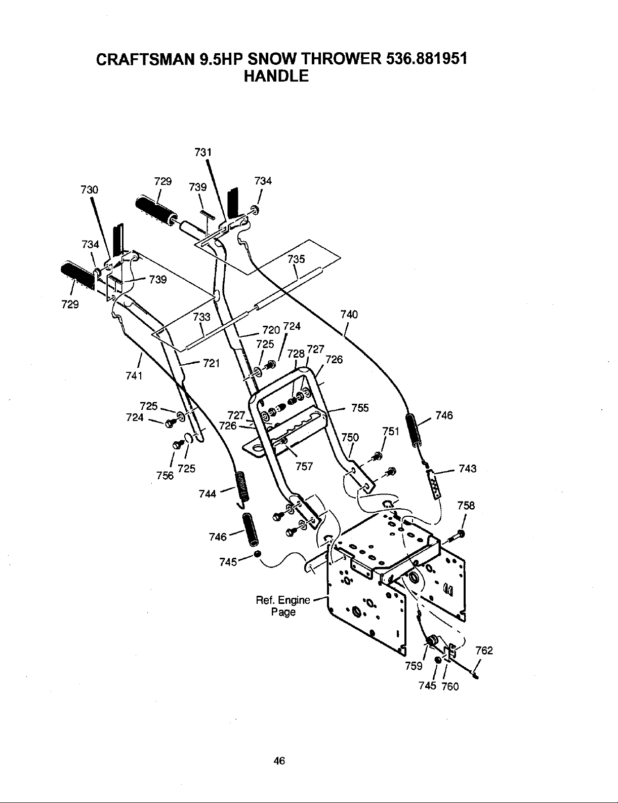
CRAFTSMAN 9.5HP SNOW THROWER 536.881951
HANDLE
731
729
730
729 734
739
741
725
73 C.
/
725
756
744
727
/
720 724
757
74O
727
726
755"_746
750 751
743
758
46
!
762
759
745 760
Page 47

CRAFTSMAN 9.5H P SNOW THROWER 536.881951
HANDLE
Key No. Pad No.
720 1501205E701
721 1501206E701
724 11234
725 71071
726 71060
727 15x144
728 11261
730 400114
731 400115
733 337381
734 761105
735 337373
739 4049
740 1501123
741 761872
Description
HANDLE, UPPER, LH (includes GRIP)
HANDLE, UPPER, RH (includes GRIP)
SCREW, 5/16-18X2.75
WASHER, FLAT
WASHER, SPTLK .31X.58X.08
NUT, 5/16-18 REGHEX YZ
STOP, RED PLASTIC
LEVER, CLUTCH DRIVE, RH (includes GRIP)
LEVER, CLUTCH DRIVE, LH (includes GRIP)
ROD, PIVOT CLUTCH
NUT, PUSH ON CAP
SPACER-HANDLE
BUMPER, RECTANGLE
CABLE, CLUTCH
CABLE, AUGER CLUTCH
743 313441
744 1673
745 15x145
746 308146
750 339541E701
751 25x021
755 337407E701
756 6751
757 313441
758 001798
759 579860
760 1501059 YZ
762 1501122
BRACKET, CABLE ADJUSTER
SPRING, AUGER CLUTCH
NUT, 1/4-20 NYLOCK YZ
BOOT, CABLE SPRING
HANDLE, LOWER
SCREW, TAP 5/16-18 X 0.75
BRKT, GEAR SELECTOR
SCREW, 5/16-18X2.00
PLATE, ADJUSTING
BOLT, HEX 1/4-20 X 1.50
SPOOL-CABLE, AUGRT CLUTCH
BRACKET, CABLE SPOOL YZ
CABLE, LOWER DRIVE 12"
47
Page 48

CRAFTSMAN 9.5H P SNOW TH ROWER 536.881951
Ref. Handle Assy
CHUTE ROD
856
855
854
855
J
861
870
Ref. Auger Housing Assy
852-9
/
852-5
852-8 852-13
852-1
/ /
852-7
852-10
852-2
852-6 869
/
852-3
48
Page 49

CRAFTSMAN 9.5H P SNOW TH ROWER 536.881951
CHUTE ROD
Key No. Part No.
852-1 1501309 YZ
852-2 164x37
852-3 1501067
852-5 579493
852-6 1501306E701
852-7 1501293
852-8 1501075 YZ
852-9 711682
852-10 578060
852-1 1 578309
852-13 578063
854 51443
Description
ASSEMBLY, YOKE & ROD
WASHER, COMPRESSION SPRING
GEAR, CHUTE ROTATION 9T
PIN, CON'ER
BRACKET, GEAR MOUNT
PIN, HAIR
ASSEMBLY, YOKE ADAPTER YZ
PIN, HAIR
PiN, UNIVERSAL JOINT
PIN, CLEVIS
HOUSING, UNIVERSAL
KNOB, CRANK
855 309312
856 73664
860 1501456
861 148
863 71045
864 71072
867 71046
868 002X98
869 15X145
870 1501074 YZ
FLATWASHER
NUT, PUSH
EYE BOLT 3/8-16X6.00
GROMMET, EYE BOLT
NUT, 3/8-16 HEXJAM
FLATWASH ER .406X.81 X.066
NUT, 3/8-16 HEXNYL
BOLT, CARRIAGE 1/4-20 X 1.00
NUT, 1/4-20 NYLOCK YZ
CRANK, ASSY CHUTE
49
Page 50

678
/
CRAFTSMAN 9.5HP SNOW THROWER 536.881951
WHEELS
679
673
675
671
654
678 650 .
655 /
652
Ref. Drive Page
655
671
673
676
Key No. Pa_ No.
650 1501563
652 1501089
653 01x193
654 15X145
655 1501114
671 712120
673 1501138
675 1501808
676 577015
677 15X145
678 239
679 73842
677
Description
SHAFT, AXLE
SPRKT & HUB
SCREW, 1/4-20 x 1.75
NUT, 1/4-20 HEX NYLOCK YZ
BEARING, AXLE
WASHER, FLAT
BUSHING, WHEEL
TIRE & RIM -RIGHT
SCREW, 1/4-20X1.75 HH
NUT, 1/4-20 HEX NYLOCK YZ
RING, RET
PIN, KLIK .25 X 1.38 DIA
680 1501809
TIRE & RIM -LEFT
5O
Page 51

BRIGGS & STRATTON ENGINE MODEL NO. 20C214-0530-E1
[ 1019 LABEL KIT ] 307 L
I 48 SHORT BLOCK I
725
_9 REPLACEMENT ENGINEI
21 _ 12
1095 VALVE GASKIETSET
1330 REPAIR MANUAL I
358 ENGIN E GASKET SET
1_3(_ 51 _ 51A
51
Page 52

BRIGGS & STRATTON ENGINE MODEL NO. 20C214-0530-E1
914
1238
281
_ _ 121 CARBURETOR OVERHAUL _JT
_ _ 1o4,_ _.I_.-- _ _'VI
_i_0._,,_ _ o"_,io_.
//_ i_<_,I 1_<:_
1230 _ 564 61
52
Page 53

BRIGGS & STRATTON ENGINE MODEL NO. 20C214-0530-E1
_8732 1288A
_7 ,72_
119eIP 12ee
731A
'11
528 _ 1_ 52 gl_
23
853 _ IOOE
366 _ 1070
332
1119 _'
334
53
Page 54
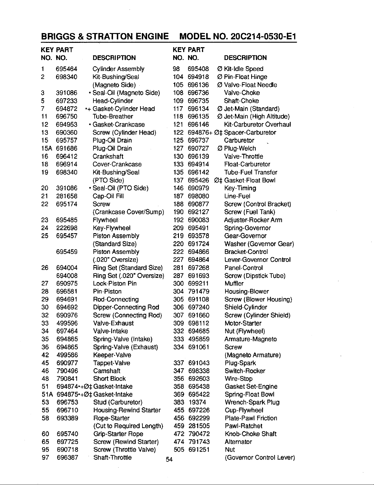
BRIGGS & STRATFON ENGINE MODEL NO. 200214-0530-E1
KEY PART KEY PART
NO, NO, DESCRIPTION NO. NO. DESCRIPTION
1 695464 Cylinder Assembly 98 695408 Q Kit-Idle Speed
2 698340 Kit-Bushing/Seal 104 694918 e Pin-Float Hinge
(Magneto Side) 105 696136 _ Valve-Float Needle
3 391086 • Seal-Oil (Magneto Side) 108 696736 Valve-Choke
5 697233 Head-Cylinder 109 696735 Shaft-Choke
7 694872 .+ Gasket-Cylinder Head 117 696134 _) Jet-Main (Standard)
11 696750 Tube-Breather 118 696135 E) Jet-Main (High Altitude)
12 694953 .Gasket-Crankcase 121 696146 Kit-CarburetorOverhaul
13 690360 Screw (Cylinder Head) 122 694876+ e:l: Spacer-Carburetor
15 695757 Plug-OU Drain 125 696737 Carburetor
15A 691686 Plug-Oil Drain 127 690727 _ Plug-Welch
16 696412 Crankshaft 130 696139 Valve-Throttle
18 696914 Cover-Crankcase 133 694914 Float-Carburetor
19 698340 Kit-Bushing/Seal 135 696142 Tube-Fuel Transfer
(PTO Side) 137 695426 e_: Gasket-Float Bowl
20 391086 • Seal-Oil (PTO Side) 146 690979 Key-Timing
21 281658 Cap-Oil Fill 187 698080 Line-Fuel
22 695174 Screw 188 690877 Screw (Control Bracket)
(Crankcase Cover/Sump) 190 692127 Screw (Fuel Tank)
23 695485 Flywheel 192 690083 Adjuster-RockerArm
24 222698 Key-Flywheel 209 695491 Spring-Governor
25 695457 Piston Assembly 219 693578 Gear-Governor
(Standard Size) 220 691724 Washer (Governor Gear)
695459 Piston Assembly 222 694866 Braeket-Con_'el
(.020" Oversize) 227 694864 Lever-Governor Control
26 694004 Ring Set (Standard Size) 281 697268 Panel_Control
694008 Ring Set (.020" Oversize) 287 691693 Screw (Dipstick Tube)
27 690975 Lock-Piston Pin 300 699211 Muffler
28 696581 Pin-Piston 304 791479 Housing-Blower
29 694691 Rod-Connecting 305 691108 Screw (Blower Housing)
30 694692 Dipper-Connecting Rod 306 697240 Shield-Cylinder
32 690976 Screw (Connecting Rod) 307 691660 Screw (Cylinder Shield)
33 499596 Valve-Exhaust 309 698112 Motor-Starter
34 697464 Valve-Intake 332 694685 Nut (Flywheel)
35 694865 Spring-Valve (Intake) 333 495859 Armature-Magneto
36 694865 Spring-Valve (Exhaust) 334 691061 Screw
42 499586 Keeper-Valve (Magneto Armature)
45 690977 Tappet-Valve 337 691043 Plug-Spark
46 790496 Camshaft 347 698338 Switch-Rocker
48 790841 Short Block 356 692603 Wire-Stop
51 694874-+E):1: Gasket-Intake 358 695438 Gasket Set-Engine
51A 694875,+O:1: Gasket-Intake 369 695422 Spring-Float Bowl
53 696753 Stud (Carburetor) 383 19374 Wrench-Spark Plug
55 696710 Housing-RewindStarter 455 697226 Cup-Flywheel
58 693389 Rope-Starter 456 692299 Plate-Pawl Friction
(Cut to Required Length) 459 281505 PawI-Ratchet
60 695740 Grip-Starter Rope 472 790472 Knob-Choke Shaft
65 697725 Screw (Rewind Starter) 474 791743 Alternator
95 690718 Screw (Throttle Valve) 505 691251 Nut
97 696387 Shaft-Throttle 54 (Governor Control Lever)
Page 55

BRIGGS & STRATTON ENGINE MODEL NO. 200214-0530-E1
KEY PART KEY PART
NO. NO. DESCRIPTION NO. NO.
523 790477
524 691876
525 790478
528 696751
529 791822
552 694674
562 691119
564 790282
592 690800
597 691696
601 95162
604 696758
604A7£0473
608 699335
613 695312
613A696705
615 694676
616 694675
632 695917
633 690998
635 691909
663 790282
689 691855
697 698113
718 690959
718A695178
725 696756
727 697465
731 790470
731A790454
732 691097
741 691288
742 692564
746 694679
798 697890
847 790476
851 692424
868 690968
883 695398
892 696749
914 693732
930 696709
957 694261
972 694260
975 696138
Dipstick
Seal-O Ring
(Dipstick Tube)
Tube-Dipstick
Hose-Primer
Grommet
Bushing-Governor Crank
Bolt
(Governor Control Lever)
Screw (Control Cover)
Nut (Rewind Starter)
Screw
(Pawl Friction Plate)
Clamp-Hose
Cover-Control
Cover-Control
Starter-Rewind
Screw (Muffler)
Screw (Muffler)
Retainer-Governor Shaft
Crank-Governor
Spring/Link
(Mechanical Governor)
_: Seal-Choke/Throttle Shaft
Boot-Spark Plug
Screw (Control Panel)
Spring-Friction
Screw (Starter Motor)
Pin-Locating
Pin-Locating
Shield-Heat
Cover-Starter Drive
Hood-Snow
Hood-Snow
Screw
(Starter Drive Cover)
Gear:Timing
Retainer-E Ring
Gear-Idler
Screw (Rocker Cover)
Dipstick/Tube Assembly
Terminal-Spark Plug
•+ Seal-Valve
•+ Gasket-Exhaust
Switch-Key
Screw (Rocker Cover)
Guard-Rewind
Cap-Fuel
Tank-Fuel
Bowl-Float
976 790221 Primer-Carburetor
977 696147 Gasket Set-Carburetor
990 695756 Key Set
998 696683 Pipe-Oil
1005 694684 Fan-Flywheel
1019 7£0459 Kit- Label
1022 6£0971 °+ Gasket-Rocker Cover
1023 698042 Cover-Rocker
1026 695177 Rod-Push
1029 690972 Arm-Rocker
1036 790466 Label-Emissions
1070 691058 Screw (Flywheel Fan)
1095 695440 Gasket Set-Valve
1100 690973 Pivot-Rocker Arm
1119 691183 Screw(Alternator)
1127 695407 Screw (Float Bowl)
1171 696754 Stud
1196 696692 Screw (Snow Hood)
1210 498144 Pulley/Spring Assembly
1211 498144 Pulley/Spring Assembly
1230 696747 Stud (Control Bracket)
1251 696762 Shield-Snow
1251A 790472 Shield-Snow
1252 696763 Screw (Snow Shield)
1275 696757 Nut (Rocker Cover)
1288 696757 Nut (Snow Hood)
1288 A698111 Nut (Snow Hood)
1298 698111 Knob-Snow Hood
1329 20B414-0017 Replacement Engine
1330 276355 Repair Manual
1351 790017 Stud (Cylinder Shield)
1352 790026 Nut (Spark Plug Shield)
Included in Engine Gasket Set
(Key Number 358)
Included in Carburetor Overhaul Kit
(Key Number 121)
:I: Included in Carburetor Gasket Set
(Key Number 977)
+ Included in Valve Gasket Set
(Key Number 1095)
NOTE: All component dimensions given in
55 U.S. inches. 1 inch = 25,4 mm
DESCRIPTION
(Rocker Arm Cover)
(Pulley)
(Spring)
Page 56

PIEZAS DE REPUESTO .......... 33
PIEZAS DE REPUESTO MOTOR... 51
GARANTiA ................... 56
REGLAS DE SEGURIDAD ........ 56
SiMBOLOS INTERNACIONALES . . . 59
ENSAMBLAJE ................. 61
GARANT|A UMITADA DE DOS AI;IOS PAPA EL QUITANIEVES CRAFTSMAN
Durante dos aSos a partir de la fecha de compra, siempre que a este quitanieves Craftsman se le
de mantenimiento, lubricacibn y afinamiento de acuerde con las instrucciones de operacibn y man-
tenimiento presentadas en el manual del usuario, Sears reparar& sin cargo alguno, cualquier defec-
to en material y mano de obra.
Si este quitanieves Craftsman es usade con prop6sitos comarciales o de arrendamiento, esta ga-
rantia sera v_lida solamente por 90 dias a partir de la fecha de compra.
Esta garantia no cubre Io siguiente:
• Elementos de desgaste normal, tales coma bujias, correas de transmisibn y pasaderes de segu-
ridad.
• Reparaciones necesarias debido al abuso o negligencia del operader, incluyende varillas dobla-
dos y otras reparaciones necesarias por falta del mantenimiento a la unidad segt_nIo recomen-
dado en las instrucciones contenidas en el manual del propietario.
EL SERVICIO DE GARANTJA SE PUEDE OBTENER LLEVANDO EL QurrANIEVES AL CEN-
TRO DE SERVIClO SEARS MAS CERCANO EN LOS ESTADOS UNIDOS. ESTA GARANTtA ES
VALIDA SOLO CUANDO ESTE PRODUCTO ES USADO EN LOS ESTADOS UNIDOS.
Esta garantia le otorgaderechos legales especificos,y asimismo es posibleque tenga otrosdere-
chos loscuales varian de un estado a otto.
Sears, Roebuck and Co., D817WA, Hoffman Estates, IL 60179
OPERACl0N .................. 65
MANTENIMIENTO .............. 71
SERVlClO Y AJUSTES .......... 73
ALMACENAMIENTO ............ 83
TABLA DE LOCALIZACION Y
REPARACION DE AVER[AS ..... 84
PEDIDO DE PIEZAS/SERVlCIO .... 88
Preste atenci n a este s mbolo, le indicaDrecauciones de seguridad importantes.
Significa--iiiATENCION!!! iiiEST¢: ALEI_TA!!! Se trata de su seguridad.
Las emanaciones de escape producidas por este
motor y ciertos componentes de esta m_quina con-
tienen qulmicos reconocidos por el Estado de Cali-
fornia come carcin6genos, tambi6n pueden produ-
cir defectos en los reci6n nacidos o causar otros da-
nos al sistema reproductivo.
Los bomes, terminales y accesorios relacionados
con la baterfa contienen plomo y compuestos del
plomo, adem_s de sustancias qulmicas que el Esta.
do de California reconoce que estos compuestos
pueden causar c_ncer y defectos como carcin6ge-
has, adem_s estas sustancias pueden producir da-
hos cong6nitos, a los bebds y adem_s de otros da-
nos al sistema reproductivo humane. DEBE LAVAR-
SE MUY BIEN LAS MANOS DESPUI_S DE MANIPU-
LAR ESTOS COMPONENTES.
56
,_ ADVERTENCIA:
col6quelo alejado de 6sta
para prevenir un arranque
accidental durante la prepa-
raci6n mantenimlento o al-
macenamiento del quitanie-
yes.
IMPORTANTE: Para prevenir
lesiones, las normas de segud-
dad exigen controlesen la unidad
que sblo puedan ser manejados
en presencia del operador. Su
quitanieves est_ equipado con
dichos controles. Por ning_n mo-
tivo intente pasar por alto la fun-
cibn del control en presencia del
operador.
Siempre desconecte
el cable de la bujla y
Page 57

CAPACITACI6N
1. Lea con atenci6n las instrucciones en el
manual de operaci6n y servicio. Familiarl-
cese completamente con los controles y
el use apropiado del quitanieves. Apren-
da a detener el quitanieves y a desen-
ganchar rt=pidamente los controles.
2. Nunca permita a nifios operar el quita-
nieves. Nunca permita que adultos ope-
ren el quitanieves sin la instrucci6n
apropiada.
3. Mantenga el drea libre de personas, es-
pecialmente nifios pequefios y mascotas.
4. Tenga mucho cuidado para evitar resba-
Iones o cafdas, especialmente cuando
est_ retrocediendo.
PREPARACI( N
,
Inspeccione completamente el _rea don-
de se usar_ el quitanieves y retire todas
las esteras, tdneos, tableros, cables, y
o_os objetos extrafios.
.
Desenganche todos los embragues antes
de hacer arrancar el motor.
3.
No opere el quitanieves sin vestir pren-
das de invierno adecuadas para trabajar
a la intempede. Vista calzado que le d_
buena tracoi6n sobre superficies resbalo-
sas.
,
Maneje el combustible con cuidado; _ste
es altamente inflamable.
(a) Use un contenedor aprobado para
combustible.
(b) Nunca quite la tapa del tanque de
combustible ni afiada combustible a
un motor en marcha o a un motor ca-
liente.
(c)
Llene el tanque de combustible al ai-
re libre y con muchocuidado. Nurica
Ilene el tanque en un recinto cerrado.
(d)
Vuelva a colocar la tape del tanque
de combustible de manera segura, y
limpie el combustible derramado.
Nunca almacene combustible o el
(e)
quitanieves con combustible en el
tanque dentro de un edit]do donde
los vapores pudiesen alcanzar algu-
na llama abierta o chispas.
(1)
Vedflque que el quitanieves tenga
suficiente combustible antes de cada
uso, y deje un espacio adicional en el
tanque puesto que el calor del motor
y/o del sol hace que el combustible
se expanda.
5. Para todos los quitanieves con motores
de arranque el_ctdco, use cables de ex-
tensi6n con certificaci6n CSNUL. Use
solamente tomacordentes que hayan si-
do instalados de acuerdo con los regla-
mentos de inspecci6n locales.
6. Jam_s intente efectuar ning0n ajuste
mientras el motor se encuentra en mar-
cha (excepto cuando el fabdcante Io re-
comiende as{ especfficamente).
7. Permita que el motor y el quitanieves se
ajusten alas temperaturas exteriores an-
tes de comenzar a despejar la nieve.
8. Siempre use gafas de seguridad o pro-
tectores para los ojos durante la opera-
ci6n o mienbas efectlJa algen ajuste o
reparaci6n a la unidad, para proteger sus
ojos de objetos extrafios que pudiesen
ser lanzados per el quitanieves.
OPERACI(SN
1. No opere este quitanieves si est_ toman-
do medicinas que puedan causar somno-
lencia o afectar su habiUdad para operar
el quitanieves.
2. No use el quitanieves si per motivos
emocionales o flsicos se le diflculta ma-
nejado de forma segura.
3. No coloque las manos o los pies cerca o
debajo de piezas en movimiento. Man-
t_ngase en todo momento a buena dis-
tancia de la abertura del tubo de
descarga.
4. Tenga mucho cuidado al operar el quita-
nieves en o a trav_s de entradas de au-
tos, senderos o caminos de grava.
Mant_ngase alerta de peligros ocultos o
tr_fico.
.
Si golpea un objeto extrafio, pare el mo-
tor, desconecte el cable de la bujia, ins-
peccione meUculosamente el quitanieves
por si hubiera algl3n dafio, y rep_relo an-
tes de arrancar el motor y operar el quita-
nieves nuevamente.
6. Si el quitanieves comienza a vibrar de
manera excesiva, pare el motor y revise-
Io inmediatamente para encontrar la cau-
sa. Generalmente, la vibraci6n es una
advertencia de alglJn problema.
7. Pare el motor cuando deje la posici6n de
operaci6n, antes de desebstruir el aloja-
miento de la barrena/propulsor o el tubo
de descarga, y cuando efectOe cualquier
57
reparacidn, ajuste o inspeccidn.
Page 58

8. CuandoUmpie,repareo inspeccione el
quitanieves, aseg_rese de que la barre-
na/propulsor y todas las partes mOviles 19.
se encuentren detenidas, y que redes los
controles est_n desenganchados. Desco-
necte el cable de la bujla y mant_ngalo
alejado de la buj{a para evitar un arran-
que accidental. 20.
9. Tome todas las precauciones posibles al
dejar el quitanieves desatendido. Desen-
ganche la barrena/propulsor, pare el me- 21.
tory retire la Ilave.
10. No haga arrancar el motor en recintos
cerrados, excepto para arrancar y para
transportar el quitanieves hacia adentro o
hacia afuera del recinto. Abra las puertas
que dan al exterior; los vapores de esca-
pe son peligrosos (conUenen MON(SXI- 1.
DO DE CARBONO, un GAS INODORO y
LETAL).
11. No use el quitanieves para limpiar _treas
de terreno inclinadas (cuestas, pendien-
tes). Tenga mucho cuidado cuando cam-
bie de direcciOn. No intente limpiar
pendientes muy pronunciadas.
12. Nunca opere el quitanieves sin que los
resguardos, placas u otros dispositivos
de seguridad se encuentren en su lugar.
13. Nunca opere el quitanieves cerca de es-
caparates de vidrio, automOviles, vidrie-
ras, sitios de carga/descarga, y similares,
sin el ajuste apropiado del _lngulo de des-
carga de la nieve. Mantenga a los nifios y
las mascotas alejados del _rea que est_
despejando.
14. No sobrecargue la capacidad del quita- 5.
nieves al intentar limpiar la nieve a una
velocidad demasiado r_lpida.
15. Nunca opere el quitanieves a altas veloci-
dades de transporte sobre superficies
resbalosas. Mire hacia atr_ls y tenga cui-
dado al retrocader.
16. Nunca descargue directamente hacia es-
pectadores ni permita a nadie frente al
quitanieves.
17. Desenganche la fuerza motriz de la ba-
rrena/propulsor cuando el quitanieves
sea trasportado o no est_ en use.
18. Utilice Onicamente aditamentos y acceso-
dos aprobados per el fabricante del quita-
nieves (tales come cadenas para las
ruedas, juegos de arranque el_ctrico,
etc.).
Nunca opere el quitanieves sin tener bue-
na visibilidad o UuminaciOn. Aseg_rese
siempre que tiene buena estabilidad, y
sujete con firmeza el mango. Camine;
nunca corra.
No trate de alcanzar _reas diflciles. Man-
tenga la estabUidad y el balance en tedo
memento.
No trate de usar el quitanieves para lim-
piar techos.
MANTENIMIENTO Y
ALMACENAMIENTO
Revise los pernos con frecuencia para
asegurar que esten bien apretados y que
el quitanieves est_ en condiciones segu-
ras de funcionamiento.
2. Nunca guarde el quitanieves con com-
bustible en el tanque dentro de un recinto
donde hubieran fuentes de igniciOn tales
come calentadores de agua y estufas,
secadoras de ropa, y similares. Permita
que el motor se enfr[e antes de guardar
el quitanieves en cualquier recinto.
3. Siva a almacanar el quitanieves per un
perfodo prolongado, siempre consulte las
instrucciones del manual del operador
donde encontrar_ consejos importantes.
4. Mantenga o reemplace las etiquetas de
seguridad e instrucciones, segOn sea ne-
cesado.
Mantenga el quitanieves en marcha unos
cuantos minutes despu_s de despejar la
nieve, para evitar que se congele la ba-
rrena/propulsor.
A ADVERTENCIA: Este qultanieves
rreno planas. Se debe tener cuidado al
usar el quitanleves en superficies IncUna-
das. NO USE EL QUITANIEVES EN SU-
PERFICIES SOBRE EL NIVEL DEL SUELO
tales como techos de residenclas, de ga-
rajes, porches u otras estructuras o cons-
trucciones similares.
es para uso en aceras, entradas
de auto y otras superficies de te-
58
Page 59

IMPORTANTE:Muchosdeestossfmbolos est_n colocados en su quitanieves o est_n impresos en
los manuales que vienen con el producto. Antes de operar el quitanieves aprenda y comprenda el
objeUvo de cada s|mbolo.
SIMBOLOS DE CONTROL Y
OPERACI6N
Despacio R_,pido
Arranque el6ctrico
Arranque de motor
@ @ o I
Motor en marcha
Ahogador Ahogador
desactivado activado Neutro Acelerador
Motor apagado Apagado Encendido
H N
Q Q
Ignlci6n Ignici6n
Bot6n cebador
Llave de encendido
dosactivada activada
Embrague
de propulsi6n
Colector
de barrena
t
Avarice
Enganchar
T
Marcha atr_s de barrena
[÷6]
Oprima para accionar
el arranque el6ctrico.
59
Embrague
O
Transmisi6n
Page 60
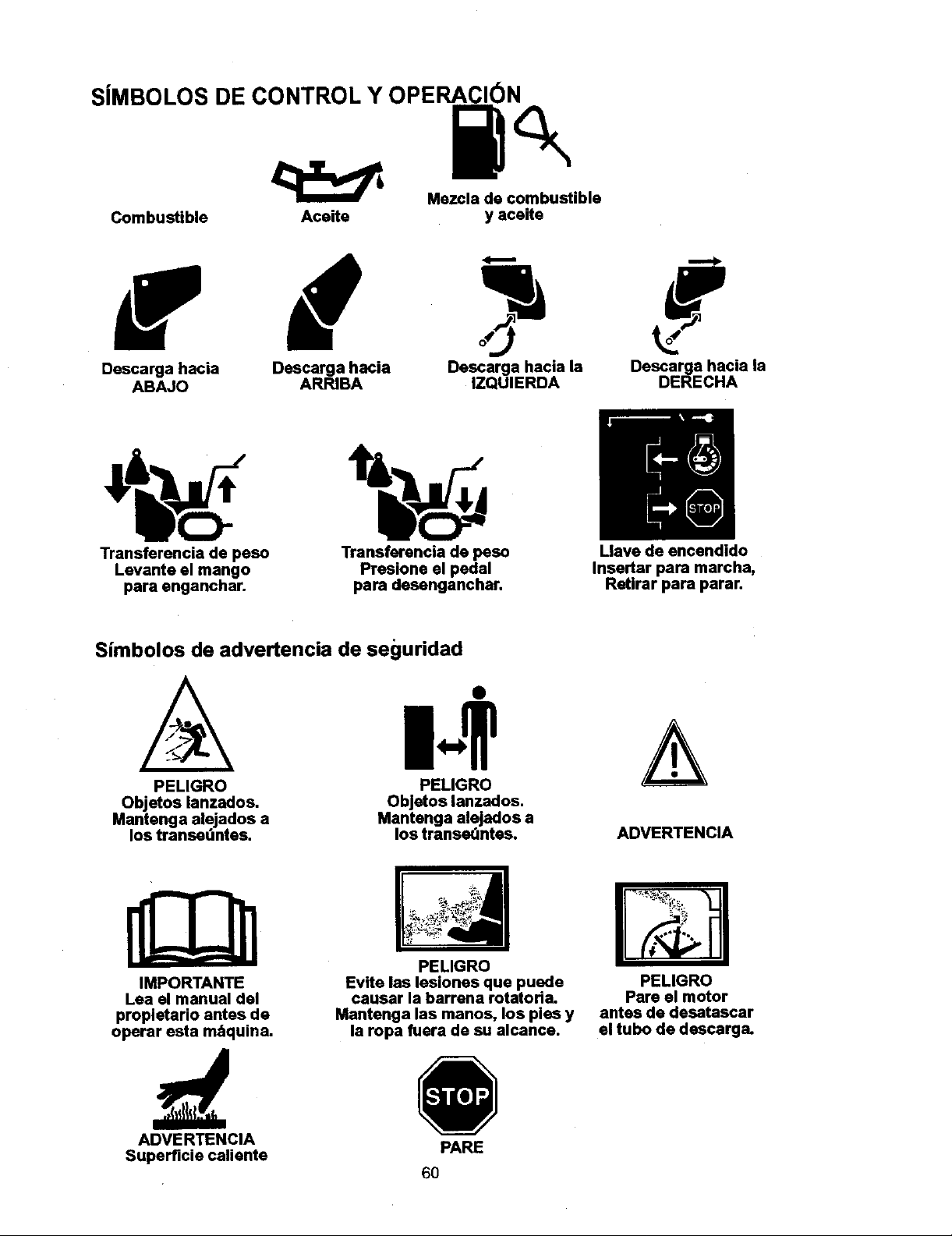
SJMBOLOS DE CONTROL Y OPERACION
Mezcla de combustible
Combustible Aceite
y aceite
Descarga hacia
ABAJO
Transferencia de peso
Levante el mango
para enganchar.
Descarga hacia
ARRIBA
Transferancia de peso
Presione el pedal
para desenganchar.
Simbolos de advertencia de seguridad
PELIGRO
Objetos lanzados.
Mantenga alejados a
los transedntes.
PELIGRO
Objstos lanzados.
Mantanga alejados a
los transe_ntes.
Descarga hacia la
IZQUIERDA
Descarga hacia la
DERECHA
Llave de encendido
Insertar para marcha,
Retirar para parar.
ADVERTENClA
IMPORTANTE
Lea el manual del
propletario antes de
operar esta m=_quina.
ADVE RTENCIA
Superficie caliente
PELIGRO
Evite las lesiones que puede
causar la barrena rotatoria.
Mantenga las manos, los pies y
la ropa fuera de su alcance.
PARE
6O
PELIGRO
Pare el motor
antes de desatascar
el tubo de descarga.
Page 61
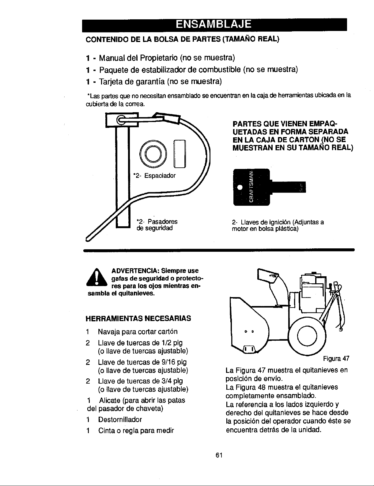
CONTENIDO DE LA BOLSA DE PARTES (TAMANO REAL)
1 - Manual del Propietario(no se muestra)
1 - Paquete de estabilizador de combustible (no se muestra)
1 - Tarjeta de garantia (no se muestra)
*Las partes que no necesitan ensamblado se encuentran en la caja de herramientas ubicada en la
cubierta de la correa.
PARTES QUE VIENEN EMPAQ-
UETADAS EN FORMA SEPARADA
EN LA CAJA DE CARTON (NO SE
MUESTRAN EN SU TAMANO REAL)
A DVERTENCIA: Siempre use
sambla el quitanleves.
gafas de segurldad o protecto-
res para los ojos mientras en-
HERRAMIENTAS NECESARIAS
1 Navajaparacortarcart6n
2 Llave de tuercas de 1/2 pig
(o Ilave de tuercas ajustable)
2 Llave de tuercas de 9/16 pig
(o Ilave de tuercas ajustable)
2 Llave de tuercas de 3/4 pig
(o Ilave de tuercas ajustable)
1 Alicate (para abrir las patas
del pasador de chaveta)
1 Destornillador
1 Cinta o regla para medir
2- Llaves de ignici6n (Adjuntas a
motor en bolsa pl_stica)
Figura 47
La Figura 47 muestra el quitanieves en
posici6n de envfo.
La Figura 48 muestra el quitanieves
completamente ensamblado.
La referencia a los lados izquierdo y
derecho del quitanieves se hace desde
la posici6n del operador cuando _ste se
encuentra detr&s de la unidad.
61
Page 62

COMO SACAR EL QUITANIEVES
DE LA CAJA
.
Ubique todas las piezas que vienen
empaquetadas por separado y
sdquelas de la caja.
NOTA: Coloque el estabilizador de
combustible en un lugar seguro
hasta que Io necesite para guardar
la unidad.
2. Quite y deseche el material de
empaque que rodea la unidad.
8. Haga un corte de arriba hacia abajo
en cada esquina de la caja y deje
los paneles sobre el suelo.
4. Corte las tiras que sujetan el eje a
la plataforma de envio.
5. Para prop6sitos de envio, los pa-
tines de ajuste de altura, van suje-
tos a la plataforma de envio. Saque
el tomillo que sujeta cada pat|n a
la plataforma. Vea la Figura 48.
6. Agarre el quitanieves por el mango
y jale para sacado de la plataforma.
PRECAMCION: NO retroceda so-
bre los cables de control.
,
Corte los amarres que sujetan el
cable de control del embrague al
mango inferior, y colbquelo alejados
del bastidor del motor.
Palanca de propulsi6n
de la barrena Palanca de
por tracci6n
Cable del
embrague
Manivela
Palanca Deflector de
descarga
Patines de
ajuste de
altura
7. Quite el material de empaque del
conjunto de los mangos.
C6MO ENSAMBLAR EL MANGO Y
EL CONJUNTO DE LA MANIVELA
,
Corte los amarres que sujetan la
palanca de cambios al mango
inferior y mueva la palanca a la
primera velocidad de avance.
,
Corte y deseche el amarre de pl&s-
tico que sujeta el conjunto de la ma-
nivela.
,
Afloje pero no quite los tornillos,
arandelas planas, arandelas de
seguridad y tuercas hexagonales
que se encuentran en los agujeros
superiores del mango inferior. Vea
la Figura 49.
o
Retire los sujetadores y el perno de
anilla de los agujeros inferiores del
mango inferior. Vea la Figura 51.
TorniU Figura 48
delm.ango
superior
bAflojepero
noquite
Tuerca ,Arandela
hexagonal d( plana de
5/16 pig 11/32 pig
Arandela de
seguridad (abierta)
de 5/16 pig
5/16 pig
Figura 49
NOTA: AsegOrese de que los
cables no queden atrapados entre
los mangos superior e inferior.
5: Levante el mango superior a la
posici6n de operaci6n.
NOTA: Si los cables se han desconec-
tado, condctelos como se muestra en la
Figura 50.
62
derecho
=de
Page 63

Palanca
%
Conexibnen "Z"
Cable de control Figura 50
6. Instale los sujetadores que quit0 en
el paso 4. NO los apriete hasta
tener todos los pernos en su lugar.
Lade"
mango
Manivela
Contratuerca
de nylon de
pig
Perno
de ;
Figura 51
7. Conecte el eje de la manivela a la
junta universal con el pasador de
horquilla. Vea la Figura 52.
8. Apriete la tuerca del perno de
anllla. AsegOrese de que el perno
de anilla est_ bien alineado y que
la manivela pueda girar libremente.
9. Apriete todos los pernos del mango
y delpanel.
NOTA: Si los cables se han desconec-
tado, con_ctelos como se muestra en la
Figura 53.
Cablede Cable de propul-
propulsion sibn de la barrena
Figura 53
C6MO ENSAMBLAR EL DEFLEC-
TOR DEL TUBO DE DESCARGA
1. Quite el perno cabeza de hongo.
Vea la Figura 54.
2. Levante el deflector del tubo de
descarga a la posicibn de opera-
cibn.
3. Monte el deflector del tubo de
descarga en el reborde con los
pernos de cabeza de hongo. Ase-
gL_resede instalar los pernos de
cabeza de hongo con la cabeza en
el parte interior del reborde.
4. Sujete con las arandelas y las con-
tratuercas,
5. Apriete firmemente las contratuer-
cas.
NOTA: Compruebe que los pernos
de cabeza de hongo en el reborde
est_n bien apretados. PERO NO LOS
APRIETE DEMASIADO.
Deflector del tubo de descarga
_Junta universal Manivela
Figura 52
Tuerca Posicibn de_
! operaciOn
/
Arandelas
63
Reborde Figura 54
Pern¢
beza de hongo
Page 64

COMO AJUSTAR LOS PATINES DE ALTURA
Su quitanieves est,. equipado con patines de
ajuste de altura ubicados en la parte exterior
del alojamiento de la barrena. Para ajustar
los patines de altura para diferentes condi-
clones, consulte "Ajuste de los patines de
altura", en la secci6n de Servicio y Ajus-
tes.
COMO ESTABLECER LA LONGITUD DE LOS CABLES
Puesto que los cables fueron ajustados en la
f_brica, no es necesario que usted los ajus-
te. Sin embargo, una vez que se instalan los
mangos en la posici6n de operaci6n, es po-
sible que los cables queden muy tirantes o
muy flojos. Si es necesario ajustarlos, con-
suite el p_rrafo =C6mo reviser y ajustar los
cables" que aparece en la secci6n de Servi-
cioy Ajustes.
_" LISTA DE REVISION
Antes de user su nuevo quitanieves, y pare
asegurar que obtenga el mejor rendimiento y
la mayor satisfacci6n de este producto de
calidad, por favor haga un repaso de la si-
guiente lista de revisi6n:
P" Se hen completado todes las instruccio-
nes de ensamblado,
P" El canal de descarga gira libremente.
P" No quedan piezas sueltas en la caja de
cart6n.
v' Revise los sujetadores. Compruebe que
todos est_n bien apretados.
Revise le presi6n de alre de las ruedas. La
presi6n de alre correcta es de 14 a 17 PSI.
En la parte lateral de les Ilantas aparece la
presi6n de aire m_xJma pare inflar las rue-
des. No sobrepase este m_xJmo.
P" En los modelos de arranque el__.=ctrico,la
unidad ha sido envieda con el cable del
sistema de arranque enchufado al motor.
Antes de utilizar la unidad, sfrvese desen-
chufar el cable de arranque del motor.
AI mismo tiempo que aprende a user su qui-
tanieves, preste mucha atenci6n a los impor-
tantes detalles a continuaci6n:
P_ El aceite del motor est_ al nivel adecuado.
Use un aceite detergente de alta calidad
clesificado como "Pare servicio SG, SH,
SJ, SL osuperior".
V' Asegt_rese que el tanque de gesolina est_
Ileno con gasolina limpia, fresca y sin plo-
mo con un octanaje mfnimo de 85.
v" FamiliaHcese con todos los controles, su
ubicaci6n y funci6n. Opere los controles
antes de hacer arrancar el motor.
64
Page 65

CONOZCA SU QUITANIEVES
LEA ESTE MANUAL DEL USUARIO Y LAS REGLAS DE SEGURIDAD ANTES DE USAR
USAR SU QUITANIEVES. Compare las figuras con su QUITANIEVES para familadzarse con
las posiciones de los diversos controles y ajustes. Guarde este manual para referencia futura.
Bot6n cebador
Llave de i
Estrangulador
Control de manual
aceleraci6n
Bot6n de arran-
que electrico
Palanca de
---.-, Palanca de propul-
si6n por tracci6n
(mano izquierda)
Manivela
Deflector de
descarga
Canal de
descarga
Pasadores de
segundad
Barraraspadora Figura44
Palanca de propulsi6n de la barrena.
Arranca y detiene la barrena y el propulsor
(recoge y lanza la nieve).
Palanca de propulsibn por traccibn - Im-
pulsa el quitanieves hacia delante o hacia
air,is.
Palanca de cambio de velocidades. Setec-
ciona la velocidad del quitanieves (6 velodda-
des hada adelante y 2 velocidades hacia
alr_is).
Manivela - Cambia la direccibn de lanza-
miento de la nieve,
Deflector del canal de descarga -Cambia la
distanda de lanzamiento de la nieve.
Canal de descarga - Cambia la altura de
lanzamiento de la nieve,
Patines de ajuste de altura . Ajustan la dis-
tancia libre en_e el terreno y el alojamiento de
la barrena.
Uave de ignici6n - Debe ser insertada para
arrancar el motor.
Manija de arranque manual - Para arrancar
el motor de fonna manual.
Estrangulador - Se usa para arrancar un
motor fT{o.
Bot6n cebador - Injecta combustibledirecta-
mente dentro del carburador o distribuidor pa-
ra unarranque r_pide en temperaluras bajas.
Control de aceleracibn. Conlmla la veloci-
dad del motor.
Bot6n de arranque _co (si la unidad Io
Uene) - Se usa para arrancar el motor usan-
de el arrancador el_ctricode 120V.
Pasadores de seguddad - Pemus disefia-
dos especialmente 10amrompeme (para prote-
ger la m_:luina) si un objeto se alasca en el
alojamiento de la barrena.
Caja de herramlentas - ContJenepasadores
de seguridad y espaciadores de repuesto.
65
Page 66

Laoperaci6ndecualquierquitanievespuede
ocasionarqueobjetosextraSosseanlanza-
dos con fuerza hacia los ojos, Io cual podrla
resultar en lesiones graves. Use siempre
galas de seguddad o protectores para los
ojos mientras opera el quitanieves.
Se recomiendan las gafas de seguddad es-
t_ndar o la m_scara de seguridad de visi6n
amplia para usarla sobre los anteojos.
A ADVERTENCIA: Lea el manual
carga hacia los transetintes. Pare el mo-
tor antes de desobstruir el canal de des-
carga o el alojamiento do la barrena y an-
tes de dejar la m_quina.
C6MO DETENERELQUITANIEVES
1. Para detener el lanzamiento de nieve,
2. Para detener las ruedas, suelte la palan-
3. Para parar el motor, empuje la palanca
COMOCONTROLARI.A DESCARGADE
NIEVE
1. Gire la manivela de control para establecer
2. Afloje la tuerca de mariposa en el de-
del propietado antes de operar
la mdquina, Nunca dirija la des-
suelte la palanca de propulsi6n de la
barrena.
ca de propulsi6n por tracci6n.
de control de aceleracl6n a la posici6n
APAGADO y saque la Ilavo de ignici6n.
la direcci6n del lanzamiento de la nieve.
flector del canal de descarga y ajuste el
deflector para establecor la distancia.
Mueva el deflector hacia (ARRIBA) para
mayor distancia, hacia (ABAJO) para
una distancia menor. Luego apriete la
tuerca de mariposa (Figura 45).
Tuerca de madposa
ca de cambio de velocidades a la ranura
apropiada del panel de control de cam-
bios.
Velocidad 1, 2 - Nieve mojada, pesada
Velocidad 3 - Nieve ligera
Velocidad 4 - Nieve muy ligera
Velocidad 5, 6 - Para transportar la uni-
dad solamente
.
Enganche la palanca de propulsi6n por
tracci6n (mano izquierda). A medida
que el quitanieves comienza a moverse,
sujete firmemente los mangos, y gul'e el
quitanieves a Io largo del camino a des-
pejar. No intente empujarlo.
3. Para mover el quitanieves en retroceso,
mueva la palanca de cambio de velocida-
des a la pdmera e segunda velocidad de
retroceso y enganche la palanca de pro-
pulsi6n per tracci6n (mano izquierda).
IMPORTANTE: Nunca mueva la palanca de
cambio de velocidades mientras la palanca
de propulsi6n por traccl6n est_ abajo.
LANZAMIENTODENIEVE
1. Empuje la palanca de propulsi6n de la
barrena (mane darecha) hacia abajo.
2. Su_ltela para detener el lanzamiento de
nieve.
C(_MOUSAREL PASADORDE
ENGANCHEDE LA RUEDA
1. La rueda del derecho va asegurada al eje
por medio de un pasador de enganche
(pasador klick). Esta unidad rue despa-
chada con el pasador en la posici6n de
enganche (a trav_s del agujero de la
rueda). Figura 46.
Pasador klick
igura 45
C(_MOAVANZARY RETROCEDER
1. Para cambiar de velocidad, suelte la pe-
lanca de propulsi6n por tracci6n (mane
izquierda) y mueva la palanca de cam-
bios a la velocidad deseada. La veloci-
dad en el terreno ser_l determinada por
las condiciones de la nieve. Seleccione la
velocidad que desea moviendo la palan-
Posici6n de
enganche Tracci6n en
2 ruedas
Figura 46
. Para facilitar la maniobra de la unidad en
condiciones de nieve Ugera, desconecte
el pasador klick de la posici6n de en-
ganche de la rueda e introd_zcalo en el
agujere para tracci6n de una rueda (des-
enganche solamente el agujero-del
eje). Figura 47.
66
Page 67

Pasadorklick
,,J_aeipaNa rilla indicadora
nivel de ac,,e_e ./
Posicidnde
NOTA: AsegOrese de que el pasador klick
est_ en la posicibn de tracci6n de una sola
rueda en el eje solamente, y no est_ inserta-
do a travOs de la posici6n de enganche.
Tracci6n en
una sola
rueda
Figura 47
ANTES DEENCENDERELMOTOR
1. Antes de dar servicio o encender el mo-
tor, familiarlcese con su quitanieves. Ase-
gl3rese de conocer la ubicaci6n de todos
los controles y entender su funcibn.
2. Revise la tensi6n del cable del embrague
antes de arrancar el motor. Consulte el
Ajuste del cable de control que apare-
ca en la seccidn de Servicio y Ajustes
de este manual.
3. Aseg_rese de que todos los sujetadores
est_n apretados.
4. Compruebe que el ajuste de los paUnes
de altura est_ correcto. Consulte el p_rra-
fo "Ajuste de los pstines de altura" que
aparece en la secci6n de Servlclo y
Ajustes de este manual.
5. Revise la presibn de los neum&ticos
(14-17 libras). No exceda el Ilmite m_xi-
mo de presibn.
REVISIONARDEL ACEITE:ANTESDE
ARRANCAREL MOTOR
NOTA: El motor fue enviado de la f_lbdca
con aceite. Revise el nivel de aceite. Afiada
aceite seg_n sea necesario.
Paraa_adiraceite
1. Asegl3rese de que la unidad se encuen-
tre sobre una superficie nivelada.
NOTA: No revise el nivel de aceite estan-
do el motor en marcha.
2. Quite la tapa/vadlla indicadora del nivel
de aceite. Revise el nivel.
3. Si es necesario, afiada aceite hasta la
Ilnea FULL (lleno) en la tapa/varilla indi-
cadora del nivel de aceite ( Figura 48).
No exceda la medida.
NOTA: El niveldelaceitedeber_lestar
entreIamarca FULL (IIeno)y lamarca
ADD (agregar) Figura 48
4. Apriete flrmemente la tapa/varilla cada
vez que revise el nivel de aceite.
NOTA: En _lreas donde la temperatura se
mantiene constante en los -6,7°C (20°F) o
menos, puede usar aceite del tipo S.A.E.
5W-30 para facilitar el encendido del motor•
COMBUSTIBLE
La certificaci6n del motor indica que 6ste
cumple con las estipulaciones de las norrnas
de regulacibn de emisiones de Califomia y
de la US EPA para motores ULGE (en equi-
po de servicio o para prados y jardines). Los
motores ULGE est_ln certificados para fun-
cionar con gasolina regular sin plomo.
_lb DVERTENCIA: Los combusti-
que usan etanol o metanol) pueden
atraer humedad la cual conduce a la se-
paracibn y formaci6n de _tcidos durante
el almacenamiento, Los gases acldicoe
pueden da_ar el sistema de combustible
de un motor mientras se encuentra en
almacenamiento.
NOTA: Para evitar problemas en el motor, el
sistema de combustible debe vaciarse antes
del guardar la unidad por 30 dlas o m_ls.
Arranque el motor y d_jelo en marcha hasta
que las Ilneas de combustible y el carbura-
dor est_n vaclos. Use gasolina fresca la si-
guiente temporada. Para mayor informaciOn
consulte la secciOn de Almacenamiento de
este manual.
Nunca use productos de Iimpieza de motor o
carburador en el tanque de combustible, de
Io contrario podrta causar dafio permanente
a la unidad.
67
bles mezclados con alcohol
(llamados gasohol o aquellos
Page 68

Lleneeltanquesolamentecongasolinafres-
ca,Iimpia,regularsinplomo,sepersinplo-
moogasolinaautomotorreformulada.NO
usegasolinaconplomo.Asegeresedeque
elrecipientequecontienelagasolinaautili-
zar,est_Iimpioy sin6xidouotraspartlculas
extrafias.Nuncausegasolinaquepueda
estarvencidadebidoasuprolongadoalma-
cenamiento.
A DVERTENCIA: La gasolina es
elamcenarla.
on marcha, cuando est6 calienta, o
cuando el quitanieves se encuantre
PARADADELMOTOR
Para parar la marcha del motor, mueva la
palanca de control de aceleraci6n a la posi-
cibn PARAR y retire la Ilave. Mantenga la
Ilave en un lugar segure. El motor no puede
arrancar sin la Ilave de ignicibn.
ARFIANQUEDEL MOTOR
Aseg_rese de qua el motor tenga suflciente
aceite. El motor del quiLanieves est_ equipa-
do con un arrancador el_ctrico de 120 voltios
de corriente alterna y con un arrancador ma-
nual. Antes de arrancar el motor, asegz_rese
de haber lefdo la infermaci6n siguiente:
inflamable y debe tener mucho
cuidado al manipularla o
No llano el tanque de combustible
mientras el quitanieves se encuontre
en un ztrea cerrada.
Mantenga la unidad alejada de llamas
abiertas o chispas el6ctricas y no fu-
me mientras liana el tanque de com-
bustible.
Nunca llano el tanque complstamente,
Llono el tanque hasta dejar entre
1/4-1/2 pulgacla de la parte superior
para proporcionar espacio para la ex.
pansi6n del combustible.
Siempra llano el tanque al aire libra y
use un embudo o boquilla para prove.
nir el derrame.
Asegt3rese de Iimplar cualquier com-
bustible derramado antes de arrancar
el motor.
Almacane la gasolina on un conten-
dor, limpio y aprobado, y mantenga la
tapa puesta y segura on el
contenedor.
A DVERTENCIA: El motor de
fe trifilar, dise_ados para funcionar con
corrianta dom6stica de 120 voltios CA. El
cable de alimentaci6n deber_ estar co-
nectado a tierra en todo momento para
evitar la posibilidad de un choque eldctri-
co qua podrla lesionar al operador.
• Siga cuidadosamento todas las ins-
• Vedfiquo qua el alambrado el4_ctrico
• Si su sistoma estd conectado a Uerra
arranque ast_ equipado con un
cable de alimentaci6n y enchu-
trucciones de la secci6n "Arranquo
del motor."
de su case tonga un siatema trifilar
conectado a tiorra. Si no est_ seguro
de esto, preg,',ntalo a un electricista
profesional. Si su case no cuenta con
un sistema de alambrado eld_.-trlco tri-
filar, no usa el arrancador ol6ctrico
bajo ninguna circunstancia.
pero no dispone do un tomacorriontos
trifilar, on un punto conveniente para
enchufar su arrancador aldctrico, pida
a un electricista profesional quo le
instale uno.
Para conectar el cable de alimenta-
cl6n de 120 voltios de CA, siamprs
conecte primero el cable a la caja del
tomacorrientes dol motor, luego an-
chufo el otro extremo en el tomaco-
rrientas trifilar conectado a tlerra. AI
desconectar el cable de alimentaci6n
eldctrica, siempre desenchufe prime-
ro el extremo en el tomacorrientes co-
nectado a tierra.
C6mo hacerarrancarel motoren frio
.
Compruebe que las palancas de propul-
sibn de la barrena y de pmpulsi6n por
traccibn estdn en la posicibn desengan-
chado.
,
Mueva el control de aceleracibn a la posi-
cibn "R/LOll)O ".
3.
Inserte la Ilave en la ranura de ignici6n.
Asegl3rese de que al meter la Ilave oye
que _sta haca un sonido de enganche.
No giro la Ilave.
,
Gire la perilla del estrangulador hacia la
derecha a la posici6n "ACTIVADO".
5.
(Arranque el_,ctrico) Conecte el cable
de alimentacibn a la caja del tomaco.
rrientes en el motor. Enchufe el otto ex-
tremo del cable de alimentaci6n en un
68
Page 69

tomacorrientes trifilar de 120 voltios CA,
conectado a Uerra.
6. Empuje el bot6n cebador de la manera
indicada a continuaci6n. Quite el dedo
del bot6n cebador entre cebados.
• No use la funci6n de cebado si la tem-
peratura est_ sobre 50 ° F (10 ° C).
• Oprima el bot6n dos veces si la tem-
peratura est_l entre 50° F (10° C) y
15° F (-10 ° C).
• Oprima el bot6n cuatro veces si la
temperatura se encuentra por debajo
de los 15° F (-10 ° C).
• Oprima el bot6n cinco veces si la tem-
peratura se encuentra por debajo de
los 0° F (-18 ° C).
7. (Arranque el_ctrico) Presione el bot6n
de arranque hasta encender el motor.
No Io presione por m_ls de 10 segundos
a la vez. Este motor de arranque el_ctri-
co cuenta con protecci6n tdrmica. Si se
sobrecalienta se detendr_l automdtica-
mente y puede ser arrancado nuevamen-
te s61o cuando se haya enfriado a una
temperatura segura (debe esperar entre
5 y 10 minutos aproximadamente).
,
(Arranque a manual) Jale r_pidamente
la manija del arranque manual. No
suelte la manija inmediatamente des-
puds de jalarla, Deje que la manija del
arranque manual se enrolle lentamente.
9. Si el motor no arranca a los 5 6 6 inten-
tos, lea las instrucciones sobre: Dificultad
para arrancar en la "Tabla de Iocalizaci6n
y reparaci6n de averfas".
C6mo hacerarrancarun motor caliente
Si est_ arrancando un motor caliente des-
puds de habedo apagado por un perfodo
corto, deje la palanca del estrangulador en la
posici6n "DESACTIVADO" y no oprima el
bot6n cebador. Si el motor no arranca, siga
las instrucciones sobre Arranque del motor
en frfo.
ARRANQUECONGELADO
Si el motor de arranque estd congelade y no
enciende el motor:
1. Jale tanta cuerda del arrancador manual
como sea posible.
2. Suelte la manija de arranque manual y
d6jela enrollarse con fuerza contra el
arrancador. Repita hasta que Iogre en-
cender el motor.
Para ayudar a evitar que se congelen el
arranque manual y los controles del motor,
proceda de la manera siguiente despu6s de
cada trabajo de remoci6n de nieve.
1. Con el motor en marcha, jale endrgica-
mente la cuerda de arranque manual es-
tirando su brazo completamente tres o
cuatro veces seguidas. El jalado de la
cuerda de arranque producir_l un sonido
de repiqueteo fuerte. Esto no causa daSo
al motor ni al arrancador.
.
Con el motor apagado, limpie toda la nie-
ve y humedad de la cubierta del carbura-
dor en el _lrea de las palancas de control.
Asimismo, mueva varias veces el control
de aceleraci6n, el control del estrangula-
dory la manija de arranque manual.
10. Una vez que el motor arranque, mueva el
control de estrangulaci6n a la posici6n
"1/2". Cuando el motor est6 trabajando
de manera uniforme, mueva el control
de estrangulaci6n a la posici6n "desac-
tivado".
11. (Arranque el_ctrico) Desconecte el ca-
ble de alimentaci6n, primero del tomaco-
rrientes y luego de la caja del
tomacorrientes.
12. Opere el motor a una velocidad de acele-
raci6n "RAPIDA" cuando est_ despejan-
do la nieve.
Deje que el motor se caliente por varies mi-
nutos antes de empezar a despejar la nieve
en temperaturas inferiores a los -18°C (0°F).
A DVERTENCIA: Nunca arran-
que el motor dentro de un re-
cinto cerrado o en _ress con
poca ventllaci6n. Los gases de escape
del motor contienen MON(_XIDO DE
CARBONO, UN GAS INODORO Y MOR-
TAL. Mantenga las manoe, los pies, el
pelo y las ropas sueltas alejadas de las
partes en movimiento tanto dol motor
como del quitanieves.
• La temperatura del silenclador y de
las plezas alrededor del silenclador
puede exceder los 150 ° F. Evite tocar
estas partes.
• NO PERMITA que nihos ni adolescen-
tes operen el quitanieves ni que est6n
cerca cuando est6 funcionando.
69
Page 70

C6MO QUITAR LA NIEVE Y
ESCOMBROS ATASCADOS DE
LA BARRENA
_ ADVERTENCIA: No intente qui-
las precauclones siguientes.
En la parte de arriba del alojamiento de la ba-
rrena se encuenlra un bast6n de limpieza. UU-
tar la nieve ni escombros atas-
cados en la barrena sin tomar
lice el bast6n de limpieza para quitar la nieve
atascada en el alojamiento de la barrena.
• Suelte la palanca de propulsi6n de la ba-
rrena.
• Mueva la palanca de control de acelera-
ci6n a la posici6n "parar".
• Retire (sin girar) la Ilave de ignici6n.
• Desconecte el cable de la bujta.
• No coloque las manos en la barrena o
canal de descarga. Use el bast6n de lim-
pieza para quitar la nieve.
CONSEJOSSOBREEL
LANZAMIENTODE NIEVE
1. Para un rendimiento mdximo de su quita-
nieves, al despejar la nieve ajuste la ve-
Iocidad sobre el terreno, NUNCA haga
este ajuste en el control de aceleraci6n.
Avance lentamente en nieve profunda,
congelada, o mojada. Si las ruedas paU-
nan, reduzca la velocidad de avance. El
motor estd disefiado para brindar un ren-
dimiento m_lximo bajo aceleraci6n total y
debe ser operado en este valor de poten-
cia en todo momento.
2. El lanzamiento de nieve es mds eficiente
si el trabajo se realiza inmediatamente
despu(_s de la nevada.
3. Para una remoci6n completa de la nieve,
traslape ligeramente cada camino adop-
tado previamente. En nieve profunda, su-
perponga los barridos entre si"para evitar
sobrecargar la m_quina.
4. La nieve deberfa ser descargada en la
direcci6n del viento siempre que sea po-
sible.
5. Para uso normal, ajuste los patines de
altura de manera que la barra raspadora
quede a 1/8 de pulgada sobre los paU-
nes. Para superficies de nieve sumamen-
te compacta, ajuste los paUnes de altura
hacia arriba de manera que la barra ras-
padora haga contacto con el suelo.
.
En superficies de grava o piedra tritura-
da, ajuste los patines de altura a 1-1;4
pulgadas por debajo de la barra raspado-
ra. Consulte el p_lrrafo "Ajuste de los
patines de altura* en la secci6n de Ser-
vicio y Ajustes de este manual. Este
ajuste es importante para que la mdquina
no recoja y lance piedras ni grava.
.
Despu_s de completar el trabajo de des-
pejar la nieve, deje el motor en marcha
por unos cuantos minutos, esto derreUnt
la nieve y hielo acumulados alrededor del
motor.
.
Limpie completamente el quitanieves
despu6s de cada uso.
9.
Quite toda acumulaci6n de hielo y nieve
y todo material extrafio del quitanieves, y
enjuague con agua (si fuera posible) para
remover toda la sal u otros qufmicos. Se-
que el quitanieves con un patio.
70
Page 71

REGISTROS DE
SERVICIO
Anote las fechas a mG Antes A Cada Cada Cada Cada Antes FECHA
dida que complete el de ca menu 5 10 25 tempo de DEL
servicio da uso do horas horas horas rada guarder SERV1CI(
..............
Lubricaci6nde la cadena
!ii!ii!ii!i!iiii iiiiiiii! iiii!!i
Cambiarel acoitedel
motor
Vaciar el tanquo de .,/
combustible
* Ajustar despu_s de 2 a 4 horas de uso.
RECOMENDACIONES GENERALES
La garantia de este quitanieves no cubre
elementos que han estado sujetos a abuse o
negligencia por parte del operador. Para re-
cibir el valor total de la garant a, el operador
deber_ dar mantenimiento al quitanieves de
acuerde alas instrucciones contenidas en
este manual.
Ser_ necesario efectuar algunos ajustes pe-
ri6dicamente para mantener su quitanieves
en buenas condiciones de funcionamiento.
DESPU¢:S DE CADA USO
• Haga funcionar la unidad para que salga
toda la nieve acumuladaen la barrena.
• Para evitar el congelamiento de la
barrena o de los controles, limpie toda la
nieve y el hielo del quitanieves.
• Revise la unidad pot si tuviera alguna
pieza suelta o dafiada.
• Apriete los sujetadores que est_n
sueltos.
• Revise y d_ mantenimiento a la barrena.
• Revise los controles para asegurarse de
que funcionan correctamente.
• Si encuentra alguna pieza gastada o
dafiada, c_mbiela inmediatamente.
ESPECIFICACION ES
CABALLOS DE
FUERZA
CILINDRADA
CALIBRE
CARRERA
CAPACIDAD DE
GASOLINA
CAPACIDAD DE
ACEITE
BUJ A:
JUEGODE
V LVULA:
"-'NTREHIERRO
DEL INDUClDO:
QUITANIEVES
CORREA DE PROPULSI6N DE LA
BARRENA
Ajuste la correa de propulsi6n de la barrena
despu6s de las primeras 2 6 4 horas, y nue-
vamente a mitad de la temporada, y des
veces cada temporada posteriormente,
(Consulte "Cbmo ajustar las correas" en
la secci6n de Servicio y Ajustes.
9.5 HP
305 cc
79mm (3,12 pulg.)
62ram (2,44 pulg.)
3 cuartos
(sin plomo)
28 onzas, 5W30
Champion Rd19LM
(Enb'ehierro 0,030pig.)
Entrada: 0,004 0,006 pig.
Escape: 0,009 0,011 pig.
0,010 0,014 pulg.
71
Page 72
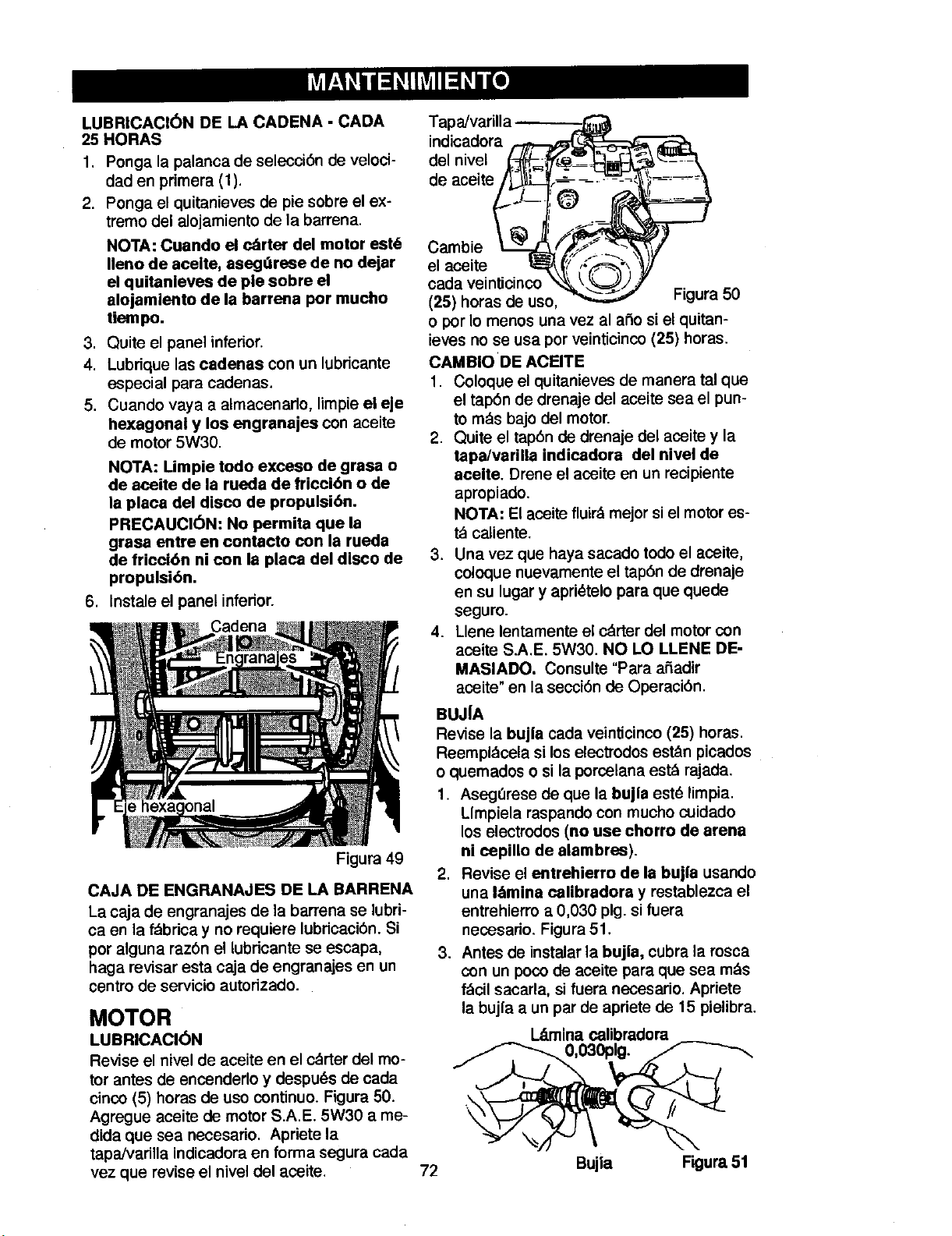
LUBRICACI6N DE LA CADENA - CADA
25 HORAS
1. Ponga la palanca de seleccibn de veloci-
dad en primera (1).
2. Ponga el quitanieves de pie sobre el ex-
tremo del alojamiento de la barrena.
NOTA: Cuando el c_rter del motor est6
Ileno de acelte, asegdrese de no dejar
el quitanleves de pie sobre el
alojamiento de la barrena por mucho
tiempo.
3. Quite el panel inferior.
4. Lubrique las cadenas con un lubdcante
especial para cadenes.
5. Cuando vaya a almacenarlo, limpie el eje
hexagonal y los engranajes con aceite
de motor 5W30.
NOTA: Limpie todo exceso de grasa o
de aceite de la rueda de fricci6n o de
la placa del disco de propulsi6n.
PRECAUCI6N: No permita que la
grasa entre en contacto con la rueda
de fricci6n ni con la placa del disco de
propulsibn.
6, Instale el panel inferior.
Cadena
Figura 49
CAJA DE ENGRANAJES DE LA BARRENA
La caja de engranajes de la barrena se lubri-
ca en la fdbdca y no requiere lubricacibn. Si
por alguna razbn el lubdcante se escapa,
haga revisar esta caja de engranajes en un
centro de servicio autodzado.
MOTOR
LUBRICACI6N
Revise el nivel de aceite en el cdrter del mo-
tor antes de encenderlo y despu_s de cada
cinco (5) hores de uso continuo. Figura 50.
Agregue aceite de motor S.A.E. 5W30 a me-
dida que sea necesario. Apriete la
tapa/vadlla indicadora en forma segura cada
vez que revise el nivel del aceite.
Tapa/varilla _---_-_
del nivel {.,_::_'_--J-_i.-_:;-J
indicadora _ _
de aceite_
Cambie Lz-i_... _.._y ___ _-_
el aceite . . _;_ ,,_ ,_
oada veinticinco _ _%__ /
(25) horas de use, _ Figura 50
o por Io menos una vez al aSo si el quitan-
ieves no se usa por veinticinco (25) horas.
CAMBIO DE ACEITE
1. Coloque el quitanieves de manera tal que
el tapbn de drenaje del aceite sea el pun-
to mds bajo del motor.
2. Quite el tap6n de drenaje del aseite y la
tapa/varilla indicadora del nivel de
aceite. Drene el aceite en un recipiente
apropiado.
NOTA: El aceite fluirdmejor si el motor es-
t_ caliente.
3. Una vez que haya sacado todo el aceite,
coloque nuevamente el tap6n de drenaje
en su lugar y apri_telo para que quede
seguro.
4. Llene lentamente el cdrter del motor con
aceite S.A.E. 5W30. NO LO LLENE DE-
MASIADO. Consulte "Para a_adir
aceite" en la seccibn de Operacibn.
BUJ|A
Revise la bujla cada veinticinco (25) horas.
Reempl_cela si los electTodos est_n picados
o quemados o si la porcelana est_ rajada,
1. Asegt_rese de que la bujla estd limpia.
LImpiela respando con mucho cuidado
los electrodos (no use chorro de arena
ni cepillo de alambres).
2. Revise el entrehierro de la bujla usando
una I&mina calibradora y restablezca el
entrehierro a 0,030 pig. si fuera
necesario. Figura 51.
3. Antes de instalar la bujla, cubra la rosca
con un poco de aceite para que sea m_s
f_cil sacarla, si fuera necesario, Apriete
la bujia a un par de apriete de 15 pielibra,
I__minacalibradora
0,030pig.
72
Bujla Figura 51
Page 73

_ ADVERTENCIA: Para prevenir
el arranque accidental del mo-
tor, siempre desconecte el ca-
ble de la bujla y mant6ngalo alejado de
dsta mlentras realiza ajustes o repara-
ciones a la unidad.
4. Afloje las tuercas de montaje que sujetan
los patines de ajuste de altura. Para bajar
la parte delantera del quitanieves, suba
los patines. Apriete las tuercas de mon-
taje. Vea la Figura 52.
NOTA: Para las superficies pedregosas o
irregulares, suba la parte delantera del quita-
nieves bajando los patines de ajuste..
COMO AJUSTAR LOS PATINES DE
ALTURA
Este quitanieves est_ equipado con dos pati-
nes de ajuste de altura, ubicados en el lado
exterior del alojamiento de la barrena. Vea la
Figura 52.
Estos patines de ajuste de altura elevan la
parte delantera del quitanieves.
Tuercas de montaje
Alojamiento
de la barrena de altura
Pat|n de ajuste
Figura 52
Para superficies duras normales, tales como
entradas de auto o senderos pavimentados
ajuste los paUnes de ajuste de altura de la
de la siguiente manera:
1. Ponga el quitanieves en una superficie
nivelada.
2. Compruebe que ambos neum_lticos ten-
gan la misma presibn de aire. La presi6n
de aire correcta es 14 a 17 PSI. No exe-
da la presi6n m_xima indicada en la cara
lateral del neum_ltico.
3. Coloque los pernos de seguridad adicio-
nales (que se encuentran en la bolsa
de partes) debajo de cada extremo de la
barra raspadora junto a los patines de
ajuste de altura.
_IL DVERTENCIA: Aseg,',rese de
sobre el suelo del _rea que se
va a limpiar. Si el Jmpulsor golpea obje-
tos tales como grava, piedras u otros
desechos, los puede lanzar con eufi-
ciente fuerza como para causar lesio-
nes personales, dalioe a la propiedad o
da_os al quitanieves.
AJUSTE DE LA BARRA
RASPADORA
Despu_,s de mucho use, la barra raspadora
met_llica se gastar_l. La barra raspadora y
los patines, siempre deben ajustarse de ma-
nera que quede un espacio de 1/8 pig. entre
la barra raspadora y la acera o el _rea que
se va a despejar.
1. Ponga el quitanieves en una superficie
nivelada.
.
Compruebe que ambos neumdticos tie-
nen la misma presibn de aire. La presi6n
correcta es de 14 a 17 PSI. No exceda
la presi6n m_lxima indicada en la cara
lateral del neum_itJco.
.
Afloje las tuercas y pernos de coche que
sujetan la barra raspadora al alojamiento
de la barrena.
4.
Ajuste la barra raspadora a la posici6n
correcta.
5.
Apriete las tuercas y pemos de coche..
Asegure que la barra raspadora quede
paralela con la acera o el _lrea que se va
a despejar.
.
Para que la barra raspadora dure m_ls
tiempo, quftela y mbntela al rev_s. Si de-
be reemplazarla debido al desgaste, qui-
te las tuercas y los pernos de coche e
instale una barra raspadora nueva.
mantener la altura necesaria
73
Page 74

AJUSTE DE LAS CORREAS
Correa de propulsibn
La correa de propulsi6n tiene una
presibn de resorte constante y no re-
quiere ningen ajuste. Si nota que em-
peza a resbalar, reempldcela. Consulte
"C6mo reemplazar la correa" en la sec-
ci6n de Servicio y Ajustes.
Correa de propulsibn de la barrena
Si el quitanieves no expulsa la nieve,
compruebe el ajuste del cable. Si es
correcto, compruebe qua la correa de
propulsi6n de la barrena estd en buen
estado. Si estd estropeada o suelta,
reempldcela (consulte "C6mo desmon-
tar la correa de propulsi6n de la barre-
na" en esta misma secci6n del manual).
1. Desconecte el cable de la bujfa.
2. Quite el tornillo de la cubierta de
la correa, Quite la cubierta de la
correa (Figura 53).
ber{a ceder media pulgada (12,5
mm) con presi6n moderada
(Figura 54). Puede que tenga que
mover la polea gu{a mds de una
vez para conseguir la tensi6n co-
rrecta.
Polea de
propulsi6n
-b e la
_,_0 Deflecci6n
--\ _\ 112 pig.
Polea
gula
puesta
Figura 54
arrena
,5ram)
Cubierta de
la correa
3. Afloje la tuerca de la polea guia de
la barrena y mueva esta eltima ha-
cia la correa un octavo de pulgada
aproximadamente (3 mm)
(Figura 56).
4. Apriete la tuerca.
5. Pida a alguien que ponga el embra-
gue de la barrena. Compruebe la
tensibn de la correa (al lado contra-
rio de la polea guia). La correa de-
6. Vuelva a poner la cubierta de la
correa.
7. Siempre que ajuste o reemplace las
correas, tambidn hard falta ajustar
los cables. (Consulte "C6mo ajustar
los cables" en esta misma secci6n
del manual).
8. Conecte el cable de las buj{as.
COMO REEMPLAZAR LAS CO-
RREAS
Las correas de pmpulsibn son especia-
les y se deben reemplazar con correas
odginales del fabricante qua podrd en-
contrar en su tienda Sears rods cerca-
ha.
Para completar algunos de estos pro-
cedimientos necesitard la ayuda de otra
persona.
Cbmo desmontar la correa de propul-
sibn de la barrena
Si la correa de pmpulsi6n estd estro-
peada, el quitanieves no expulsard la
nieve. Reemplace la correa de la si-
guiente manera.
1. Desconecte el cable de la buj{a.
74
Page 75

,
Afloje los pernos a cada lado del
panel inferior (Figura 55).
3. Quite el panel inferior.
Perno Panel
"_"_ _ _. " 'nferi_Alolr
_ mieato
_j de_ba-
_" 1 rrena
Figura 55
4. Quite el tornillo de la cubierta de
la correa. Quite la cubierta
(Figura 53).
5. Afloje la gu|a de la correa. Separe
la gu|a de la polea de propulsibn
de la barrena (Figura 56).
6. Separe la polea gu|a de la correa
de propulsibn de la barrena.
7. Quite la correa de propulsibn vieja
de la polea de propulsibn de la
barrena y de la polea del motor.
Instale una correa de propulsibn
de la barrena nueva original de fd-
brica que haya comprado en un
centro de servicio Sears.
8. Instale la correa de propulsibn de
la barrena nueva en la polea de
propulsibn yen la polea.
9. Ajuste la correa de propulsibn de
la barrena. Consulte "C6moajustar
la correa de propulsi6n de la barre-
na" en la secci6n de Servicio y
Ajustes.
10.Ajuste la guia de la correa. Consul-
te "C6mo ajustar la gufa de la co-
rrea" en la secci6n de Servicio y
Ajustes.
11. Instale la cubierta de la correa.
Apriete el tornillo (Figura 53).
12. Revise los cables. Consulte "Chino
revisar y ajustar los cables" en la
seccibn de Servicio y Ajustes.
13. Instale el panel inferior (Figura 55).
14. Apriete los pernos a cada lado del
panel inferior.
15. Conecte el cable de la bujia.
J
Correa de
Polea gufa ae
Anillo E
Eje de la
placa oscilante
Gula de la correa
Polea de propulsi6n
de la barrena
Correa de propulsibn
Resorte de
propulsibn
Correa de
propulsibn
Polea de
pmpulsibn
Polea del motor
Figura 56
75
Page 76

Cbmo desmontar la correa de
propulsi6n
Si el quitanieves no se mueve hacia
adelante, asegt3rese de que la correa
de propulsibn no est_ excesivamente
desgastada o daSada. Si Io est&,
reempl&cela de la siguiente manera.
1. Desconecte el cable de la bujia.
2. Quite la correa de propulsibn de la
barrena. Consulte "C6mo desmon-
tar la correa de propulsibn de la ba-
rrena" en la seccibn de Servicio y
Ajustes.
.
Quite el anillo E de uno de los ex-
tremos del eje de la placa oscilan-
te. Quite este eje para que la placa
oscUante gire hacia adelante
(Figura 56).
4. Quite el resorte de propulsi6n.
sujeta (Figura 57).
!
Marcas de alineamiento Figura 57
NOTA. Si la transmiaibn no fun-
ciona una vez qua haya substitui-
do la corraa de propulsi6n,
asegl_rese de que la placa osci-
lante se encuentre entre las dos
marcas de alineamianto.
,
Quite la correa de propulsibn vieja
de la polea de propulsi6n y de la
polea del motor. Instale una co-
rrea de propulsibn original de f_,-
brica disponible an un centro de
servicio Sears.
6. Instale la nueva correa de propul-
sibn en la polea de propulsi6n y
en la polea del motor.
7. AsegQrese de que la polea guia de
propulsibn est6 alineada con la
correa de propulsi6n.
8. Conecte el resorte de propulsibn.
9. Instale el eje de la placa oscilante
y suj_telo con el anillo E.
10. La parte inferior de la piaca osci-
lante debe quedar entre las mar-
cas de alineamiento. AsegOrese
de qua la placa oscilante est_ bien
11. Instale y ajuste la correa de pro-
pulsibn do la barrena. CensuRe
"Chino desmontar la correa de pro-
pulsi6n de la barrena" en la seccibn
de Servicio y Ajustes.
12. Ajuste la guia de la correa. Consul-
te "C6mo ajustar la gufa de la co-
rrea" en la secci6n de Servicio y
Ajustes.
13. Instale el panel inferior (Figura 55).
14. Apriete los pernos a ambos lados
del panel inferior.
15. Instale la cubierta de la correa.
Apriete el tornillo (Figura 53).
16. Revise el ajuste de los cables. Con-
suite "Cbmo revisar y ajustar los
cables" en la secci6n de Servicio y
Ajustes.
17. Conecte el cable de la bujia.
76
Page 77

AJUSTES DE LA CORREA GUIA
1. Quite el cable de la bujia.
2. Pida a alguien que ponga el propul-
sor de la barrena.
3. Mida la distancia entre la guia de la
correa y la correa. La distancia de-
be ser de 1/8 de pulgada (3,175
mm) para la gu[a. (Figura 58).
/ "_ Gula de '
Accesodo "Z"
Figura 59
_- --_O_ acorrea
Polea _ J \_ 1/8 pig.
gula t. _._.\! (3,175 mm)
de la _(_ - \\
barrena"_ \\
en Lol
funciona- _'_
miento I ____.-
Figura 58
4. Si necesita hacer algQn ajuste, aflo-
je el perno de montaje de la guia de
la correa. Ponga la guia en la posi-
ci6n correcta. Apriete el perno.
5. Vueiva a instalar la cubierta de la
correa.
6. Vuelve a conectar el cable de la buj[a.
C6MO REVISAR Y AJUSTAR
LOS CABLES
Los cables se ajustan en la f_brica y no
deberia ser necesario ajustarlos. Si se
se dan de si o est_n flojos, ajOstelos.
Siempre que cambie o ajuste las
correas tendr_ que ajustar los cables.
Para asegurarse de que est_n bien
ajustados, suelte el accesorio "Z" en
la palanca de propulsibn
(Figura 59).
1. Mueva la palanca de propulsibn to-
do Io que pueda hacia adelante
(hasta que toque el tope de pl_sti-
co). Sujete bien el cable, observe
la posicibn del accesorio con res-
pecto al agujero en la palanca de
propulsi6n.
, El centro del accesorio "Z" debe es-
tar entre el centro y la parte super-
ior del agujero en la palanca de
propulsi6n. Ajuste el cable de pro-
pulsibn de la barrena o el cable de
propulsibn por tracci6n segt_n sea
necesario, siguiendo las instruccio-
nes a continuacidn,
Ajuste del cable de propulsi6n de la
barrena
1. Deje el motor en marcha hasta que
el tanque de combustible queda va-
o[o y el motor se pare,
2. Levante el quitaniaves con el extre-
mo frontal del alojamiento de la ba-
rrena hacia abajo,
3, Meta el cable pot el resorte hasta
exponer la porci6n roscada del ca-
ble (Figura 60).
Extremo cuadrado
Resorte
del cable
O
Contratuerca
Figura 60
,
Sujete el extremo cuadrado de la
parte roscada con unos alicates y
ajuste la contratuerca hacia afuera
o hacia adentro hasta conseguir el
ajuste correcto. Vueiva a meter el
cable por el resorte y con_ctelo.
77
Page 78

AJUSTES DEL CABLE DE PROPULSI6N
1. Deje el motor en marcha hasta que
el tanque de combustible quede va-
c[oy el motor se pare.
2. Levante el quitanieves con el extre-
mo frontal del alojamiento de la ba-
rrena hacia abajo.
3. Afloje los pernos a cada lado del
panel inferior (Figura 61).
Perno Panel infedor
_ _ miento
_2_. _ de la
=°
X,_ Perno __
Figura 61
7. Meta la parte inferior del cable de
propulsibn por el soporte de ajus-
te del cable hasta que pueda sacar
el gancho "Z".
8. Saque el gancho "Z" del soporte
de ajuste del cable. Mueva el gan-
cho "Z" hacia abajo hasta el si-
guiente agujero de ajuste.
9. Jale el cable de propulsibn por el
soporte de ajuste.
10. Ponga el manguito del cable sobre
el soporte de ajuste del cable.
11. Instaie el gancho "Z" en la palan-
ca de propulsibn (Figura 59).
12. Para revisar el ajuste, baje la palan-
ca de propulsi6n y compruebe la
Iongitud de uno de los resortes de
propulsibn. Si el ajuste es el co-
rrecto, la Iongitud del resorte de
propulsi6n es:
min. 3 pig. (76 mm.)
m&x. 3-3/8 pig (85 mm.)
(Figura 63).
4. Quite el panel inferior.
5. Desconecte el accesorio "Z" de la
palanca de propulsibn (Figura 59).
6. Saque el manguito del cable del
soporte de ajuste del cable
(Figura 62).
Cable de
propulsibn
\
Manguito
del cable
Gancho "Z"
Soporte de ajuste
del cable
Figura 62
propulsi6n Figura 63
78
Page 79

COMO AJUSTAR O REEMPLAZAR LA RUEDA DE FRICCION
Cbmo revisar la rueda de friccibn
Si el quitanieves no avanza, revise la
correa de propulsi6n por tracci6n, el ca-
ble de propulsibn o la rueda de fricci6n.
Si la rueda de fricci6n est_ gastada o
dafiada, hay que cambiarla. Ver
"Reemplazo de la rueda de fricci6n" en
esta secci6n. Si la rueda de fdcci6n no
est_ gastada o dafiada, revisela de la
siguiente manera.
1. Deje el motor en marcha hasta que
el tanque de combustible quede va-
cio y el motor se pare.
2. Ponga el quitanieves en posici6n
vertical sobre la parte delantera del
alojamiento de la barrena
(Figura 64).
3. Desconecte el cable de la buj{a.
4. Afloje los pernos a cada lado del pa-
nel inferior (Figura 64).
5. Quite el panel inferior.
6. Ponga la palanca de cambio de
velocidades en la posici6n m_s
lenta de velocidad de avance.
, p _ferior
12 y 13 pulgs. 4-1/8"
16 pulgs. 4-5/16"
Si la rueda de fricci6n no est& en la
posici6n correcta, ajOstela de acuer-
do alas instrucciones siguientes.
Figura 65
Cbmo ajustar la rueda de friccibn
1. Coloque la palanca de cambio de
velocidades en la posici6n robs
lenta de velocidad de avance.
2. Afloje los pernos en la vara de
control de velocidad (Figura 66).
3. Mueva la rueda de friccibn a la po-
sici6n correcta (Figura 65).
4. Apriete los pernos que hay en la
vara de control de velocidad
(Figura 66),
5. Instale el panel inferior (Figura 64).
_ __._ena
,
Fijese en la posici6n de la rueda de
friccibn (consulte la Figura 65). La
distancia correcta "A" desde el lado
derecho de la rueda de friccibn
hasta la parte exterior de la caja
del motor es la siguiente:
Tamafio Ilanta Distancia "A"
6. Apriete los pernos que hay a cada
lado del panel inferior.
iI --
VarAfldo_e,c°_n:pledr:o_:I_ #_/// [U
F-----:
Figura 66
79
Page 80

Cbmo reemplazar la rueda de fricci6n
Si la rueda de fricciSn est_l gastada o
da5ada, el quitanieves no avanza. La
rueda de friccibn se debe cambiar de la
siguiente manera.
1. Deje el motor en marcha hasta que
el tanque de combustible quede va-
cfoy el motor se pare.
.
Ponga el quitanieves en posicibn
vertical sobre la parte delantera del
alojamiento de la barrena (4).
(Figure 64).
3. Desconecte el cable de la bujia.
4. Quite los sujetadores que fijan la
Ilanta derecha. Quite la Ilanta de-
recha del eje (Figura 67)
5. Afloje los pemos que haya a cada
lado del panel inferior.
6. Quite el panel inferior.
Panel inferior
Llanta
Figura 67
Cadena
Figura 68
7. Quite los sujetadores que fijan el
engranaje de propulsi6n al eje
(Figura 68).
8. Quite la Ilanta izquierda, el eje y el
engranaje de propulsibn.
9. Quite los cuatro pernos que retie-
nen los cojinetes a cada lado del
eje hexagonal (Figura 69).
10. Quite el eje hexagonal y los coji-
netes.
NOTA: F|jese especialmente en la
posicibn de las arandelas en el eje
hexagonal.
Figura 69
11. Quite los tres sujetadores que re-
tienen la rueda de friccibn en el
cubo (Figura 70).
8O
Page 81

12.Quite la rueda de friccibn del cu-
bo. Deslice la rueda de friccibn
fuera del eje hexagonal.
13. Instale la nueva rueda de friccibn
en el cubo con los sujetadores que
quit6 antes.
14. Instale el eje hexagonal y los coji-
netes con los cuatro pernos que
quit6 antes (Figura 71).
18. Asegerese de que la rueda de fric-
ci6n y la placa del propulsor de dis-
co no tienen nigrasa ni aceite.
19. Instale el panel inferior (Figura 67).
20. Apriete los pernos a cada lado del
panel inferior.
21. Instale la Ilanta derecha en el eje
con los sujetadores que quit6 antes.
Aseg_rese de que haya instalado
correctamente las arandelas en
su posicibn original. Asimismo,
compruebe que las doe arande-
las est6n correctamente alinea-
das con los brazos del impulsor.
15. Aseg0rese de que el eje hexagonal
gira libremente.
16. Instale la Ilanta izquierda, el eje y el
engranaje de propulsi6n con los
sujetadores que quitb antes. Instale
la cadena en el engranaje de pro-
pulsibn (Figura 68).
17. Revise el ajuste de la rueda de fric-
cibn. Consulte "C6mo ajustar la rue-
da de fricci6n" en esta secci6n.
I
22. Conecte el cable de la bujia.
Ruedade
Sujetadores Cubo fdcci6n
\
qe hexagonal
Sujetadores
Figura 70
!
Brazosdel impulsor
Cojinetes
\
\
Arandela
Arandela
/
C_inetes
/
Arandela
._ Arandela
Figura 71
81
Page 82
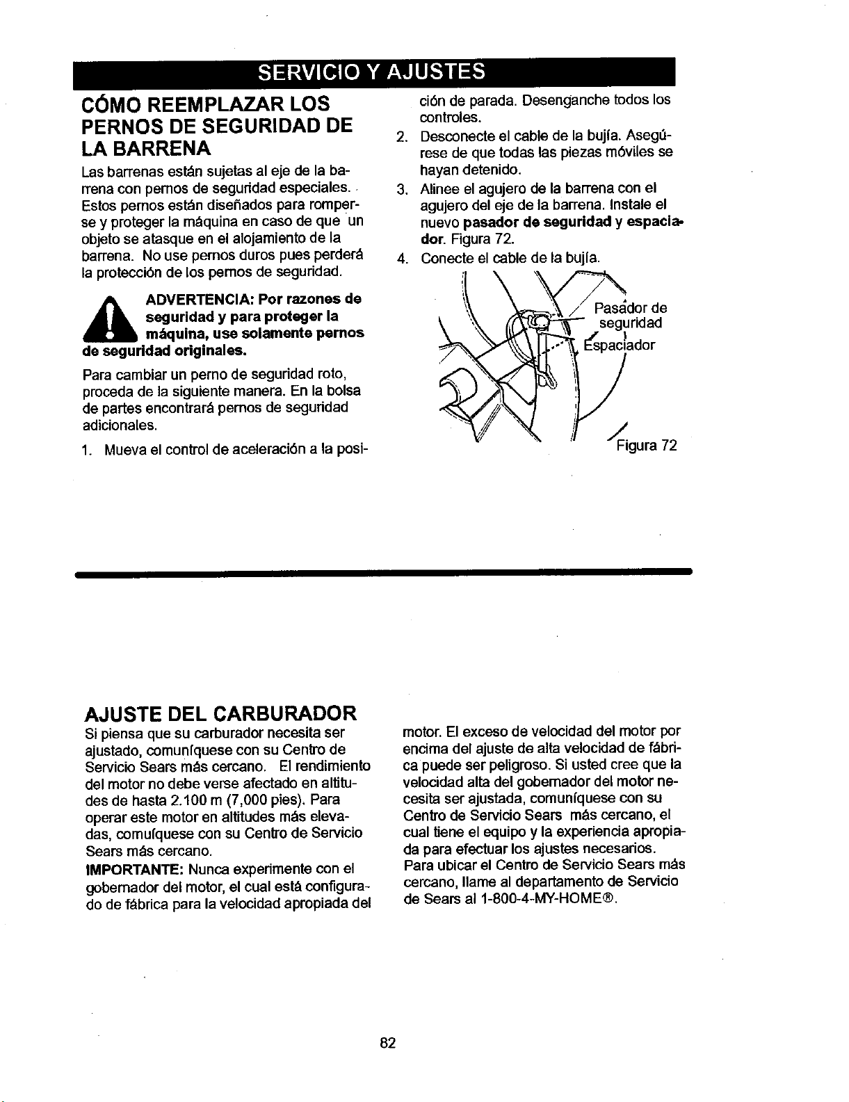
C6MO REEMPLA]_AR LOS
PERNOS DE SEGURIDAD DE
LA BARRENA
Las barrenas est_n sujetas al eje de la ba-
rrena con pemos de seguddad especiales.
Estos pernos est_m disel'iados para romPer-
se y proteger la m_quina en caso de que un
objeto se atasque en el alojamiento de la
barrena. No use pernos duros pues perder_l
la protecci6n de los pemos de seguridad.
ci6n de parada. Desenganche todos los
controles.
2. Desconecte el cable de la bujfa. Aseg_l-
rese de que todas las piezas m6viles se
hayan detenido.
3. Alinee el agujero de la barrena con el
agujero del eje de la barrena. Instale el
nuevo pasador de seguridad y espacla-
dor. Figura 72.
4. Conecte el cable de la buj{a.
_ DVERTENCIA: Por razones de
de seguridad originales.
Para cambiar un perno de seguridad roto,
proceda de la siguiente manera. En la bolsa
de partes encontrard pemos de seguridad
adicionales.
1. Mueva el control de aceleraci6n a la posi-
seguridad y para proteger la
m_quina, use selamente pernos
//Pasador de
._ _- seguridad
ador
_gura 72
AJUSTE DEL CARBURADOR
Si piensa que su carburador necesita set
ajustado, comunfquese con su Cen_'o de
Servicio Sears m_ls cercano. El rendimiento
del motor no debe verse afectado en altitu-
des de basra 2.100 m (7,000 pies), Para
operar este motor en altitudes m_s eleva-
das, comul'quese con su Centro de Servicio
Sears m,_s cercano.
IMPORTANTE: Nunca experimente con el
gobemador del motor, el coal est_lconfigura-
do de f_brica para la velocidad apropiada del
motor. El exceso de velocidad del motor por
encima del ajuste de alta velocidad de f_lbri-
ca puede ser peligroso. Si usted cree que la
velocidad alta del gobemador del motor ne-
cesita set ajustada, comun|quese con su
Centro de Servicio Sears m_is cercano, el
cual Uene el equipo y la experiencia apropia-
da para efectuar los ajustes necesarios.
Para ubicar el Centro de Servicio Sears m_is
cemano, Ilame al departamento de Servicio
de Sears al 1-800-4-MY-HOME®.
82
Page 83

_ DVERTENCIA: Nunca guar-
de su quitanieves en am-
bientes interiores o en un
&tea cerrada y mal ventilada, Si
queda gasolina en el tanque, los va-
pores podr|an alcanzar alguna lla-
ma expuesta, chispa o llama piloto
de una caldera, calentador de
agua, secadora de ropa, cigarrillo,
etc,
Para prevenir el daSo (si el quitanieves
no se usa por m_ls 30 dfas) prep&relo
como se indica a continuaci6n.
QUITANIEVES
1. Limpie todo el quitanieves.
2. Lubrique to<los los puntos de lubri-
caci6n. Consulte la secci6n de Man-
tenimiento.
3. AsegL_rese de que todas las tuercas,
pernos y tornillos est_n bien apreta-
dos. Inspeccione todas las piezas
m6viles visibles para detectar da-
r_os,roturas y desgaste. Haga los
reemplazos necesarios.
4. Retoque todas las superficies oxida-
das o que tengan la pintura saltada;
Ifjelas suavemente antes de aplicar
la pintura.
5. Cubra las piezas de metal expuesto
del soplador del alojamiento de la
barrena y del impulsor, con un anti-
corrosivo, tal como un lubricante en
aerosol.
NOTA: Una revisi6n o afinamiento
anual hecho en un Centro de Servicio
Sears es una buena manera de asegu-
rar que su quitanieves le brinde el m_-
ximo rendimiento la siguiente
temporada.
MOTOR
Deber_l sacar la gasolina del tanque o
prepararla para prevenir la formacibn
de dep6sitos de goma en el tanque, ill-
tro, manguera y carburador durante el
almacenamiento. Adem_s, durante el
almacenamiento, la gasolina mezclada
con alcohol que contiene etanol o me-
tanol (llamada a veces gasohol) atrae
agua, y 6sta actlJa sobre la gasolina
formando &cidos que daSan el motor.
1. Deje el motor en marcha hasta que
el tanque quede vac{o y el motor se
pare.
2. Si no quiere sacar la gasolina, use el
estabilizador de combustible provis-
to con la unidad, o compre estabili-
zador de combustible Craftsman
N0m. 3550. ASada el estabilizador
de combustible a cualquier cantidad
de gasolina que permanezca en el
tanque para minimizar los dep6sitos
de goma y &cido. Si el tanque est&
casi vac{o, mezcle el estabilizador
con gasolina fresca en un recipiente
separado y aSada un poco de esta
mezcla al tanque.
3. Siempre siga las instrucoiones del
envase del estabilizador. Luego de
aSadir el estabilizador, encienda el
motor y ddjelo correr por 10 minutos
por Io menos para permitir que la
mezcla alcance el carburador.
,
Cambie el aceite del motor
5.
Lubrique el &rea del pist6n/cilindro.
Para hacerlo, saque primero la bujfa
y coloque una gotas de aceite de
motor limpio en el z6calo de la bujia.
Luego cubra el z6calo con un paso
para absorber el exceso de aceite. A
continuaci6n, jale la manija de arran-
que manual unas dos o tres veces
para hacer girar el motor. Finalmen-
te, reinstale la bujfa y conecte el ca-
ble.
OTRAS INDICACIONES
1. Si fuera posible, guarde su quita-
nieves dentro de un recinto, cubd_n-
dolo para protegerlo del polvo y la
suciedad.
,
Si debe guardar el quitanieves afue-
ra, col6quelo sobre bloques para le-
vantarlo del suelo.
3. Cubra el quitanieves con una cubier-
ta protectora apropiada que no re-
tenga humedad. No use pl._stico.
IMPORTANTE: Nunca cubra el quita-
nieves mientras las _reas del motor y
del escape est_n todavia calientes.
83
Page 84

PROBLEMA CAUSA CORRECCION
Dificultad de Bujia defectuosa. Reemplase la buj{a defectuosa.
arranque
Agua o suciedad en el sistema Saque el combustible del tanque.
de combustible. A_ada combustible fresco.
El motor funclona Lfnea de combustible bloqueada, Limpie la I{nea de combustible;
err_ticamente falta de combustible o mezcla de revise la existencia de
combustible vieja, combustible en el tanque,
agregue gasolina fresca si es
necesario.
El motor se para Unidad funcionando con
estrangulador activado.
El motor funciona
err_ticamente;
p_rdida de
)otencia
Vibrack_n excesiva
La unidad no se
_uede propulsar a
sl misma
La unidad no
descarga la nieve
Agua o suciedad en el sistema
de combustible.
Piezas sueltas; propulsor
da_ado.
Correa de propulsibn per
traccibn floja o datiada.
Ajuste incorrecto del cable de
propulsibn per tracci0n.
Rueda de fdccibn gastada o
daiiada.
Correa de propulsibn de la
barrena suelta o da5ada.
El cable de control de la barrena
no est_ ajustado correctamente.
Coloque la palanca de
estrangulador en la posicibn
DESACTIVADO.
Saque el combustible del tanque.
Aflada combustible fresco.
Pare el motor inmediatamente.
Saque la Ilave de encendido.
Apriete todos los sujetadores y
realice todas las reparaciones
necesarias. Si la vibraciSn
contini3a, Ileva la unidad a su
Centro de Servicio Sears,
Reemplace la correa de
propulsi6n por traccibn.
Ajuste cable de propulsi6n per
traccibn.
Reemplace la rueda de fdccibn.
Reemplace la correa de
_ropulsibn de la barrena.
Ajuste el cable de control de la
barrena.
3erno de seguridad roto.
Canal de descarga obstruido
Objeto extraCio atascado en la
barrena.
84
Reemplaco el pemo de
seguddad.
Pare el motor inmediatamente y
desconecte el cable de ia bujfa.
Limpie el canal de descarga y la
parte de adentro del alojamiento
de la barrena.
Pare el motor inmediatamente y
desconecte el cable de ia buji'a.
Retire el objeto atascado en la
barrena.
Page 85
SEARS, ROEBUCK AND CO.
Garantia limitada de cumplimiento con el Sistema Federal
de control de emisiones y con el sistema de control de
emisiones del Estado de California
Motores peque_os para vehiculos todo terreno
CONTROL DE EMISlONES DE
CALIFORNIA Y DE LA AGENClA DE
PROTECClON AMBIENTAL (EPA) DE
E.U,A. - DECLARACION DE LA
GARANT[A
La Agencia de Protecci6n Ambiental de los
Estados Unidos ("EPA"), el Consejo de Cali-
fornia para los Recursos del Aire ("CARB") y
Sears, Roebuck and Co. tienen el placer de
explicar Io que es la Garantfa Federal y de Ca-
lifornia para Sistemas de Control de Emisio-
nes de su nuevo motor pequefio para
vehlculos todo terreno. En California, los mo-
tores pequefios para vehlculos todo terreno
de modelo 1995 y modelos de afios posterio-
res deben ser disefiados, construidos y equi-
pados para cumplir con las estrictas normas
anti centaminaci6n del Estado. En otros esta-
dos, los motores modelo 1997 y modelos de
afios posteriores deben estar disefiados,
construidos y equipados, al momento de su
venta, para que cumplan con las disposicio-
nes de la EPA acerca de motores pequefios
para veh[culos todo terreno. Sears, Roebuck
and Co., garanUzar_ el sistema para el conkol
de emisiones de su motor pequefio para vehf-
culos todo terreno por los periodos de tiempo
que se mencionan m_ls adelante, siempre y
cuando su motor pequefio para veh[culos todo
terreno no haya sutrido alg_n abuso, negligen-
cia, modificaci6n no aprobada o mantenimien-
to indebido.
Su sistema para el control de emisiones puede
incluir partes como el carburador, el sistema
de encendido y el sistema de escape. Tambi_n
puede incluir el sistema de descompresi6n y
otras unidades relacionadas con las emisio-
nes.
Cuando surja una condici6n protegida por la
garantfa, Sears, Roebuck and Co., reparar_l
su motor pequefio para vehlculos todo terreno
sin costo alguno para usted pot concepto de
diagn6stice, partes y mano de obra.
SISTEMA PARA EL CONTROL DE
EMISIONES DEL FABRICANTE -
COBERTURA DE LA GARANTiA
Los sistemas para el control de emisiones del
modelo 1995 y modelos de afios posteriores
de motores pequefios para vehfculos todo te-
rreno en California est_n garanUzados por dos
afios, tal y come se menciona en la presente
garantla. En ot]os estados, los motores mode-
Io 1997 y modelos de afios posteriores tam-
bi6n est_ln garantizados por dos afios. En
caso de que, durante dicho periodo de la ga-
rantia, cualquier pieza del motor, relacionada
con emisiones estd defectuosa en sus mate-
dales o mano de obra, Sears, Roebuck and
Co., reparar_ o cambiar_l dicha pieza.
RESPONSABILIDADES DEL
PROPIETARIO DE LA GARANT|A
Como propietario del motor pequefio para ve-
hfculos todo terreno usted es responsable de
que se Ileve a cabo el mantenimiento requeri-
do que se menciona en el Manual del usuario,
pero Sears, Roebuck and Co., no negard la
garantfa enicamente debido a la falta de un re-
cibo o a qua usted no proporcione una prueba
escrita de que se ha Ilevado a cabo el manteni-
miento programado.
No obstante, usted, como propietario del mo-
tor pequefio para veh|culos todo terreno, de-
berd estar censciente de que Sears, Roebuck
and Co., le puede negar la cobertura de la ga-
rantfa si su motor o alguna parte del mismo ha
fallado debido a abuso, negUgencia, manteni-
miento inadecuado o modificaciones no apro-
badas.
Usted es responsable de presentar su motor
pequefio para veh[culos todo terreno en el Ta-
ller de Servicio Autodzado de Sears, Roebuck
and Co., en cuanto surja el problema. Las re-
paraciones bajo la garantfa deben Ilevarse a
cabo dentro de un periodo de tiempo razona-
ble que no exceda de 30 dfas.
Se puede programar el servicio de garantfa
Ilamando al Taller de Servicio Autodzado de
85
Page 86

Sears,RoebuckandCo.,oaSears,Roebuck
andCo.,al 1-800-473-7247(llamadagratui-
taenE.U.A.).
NOTA IMPORTANTE
Esta declaraci6n de garantl'a explica los dere-
chos y las obligaciones que usted tiene de
conformidad con la Garant[a del Sistema para
el Control de Emisiones ("Garantfa SCE"), la
cual Sears, Roebuck and Co., le proporciona
de conformidad con las leyes de California.
Consulte tambi_n lea Garantl'as Limitadas de
Sears, Roebuck and Co., que se adjuntan a la
Garantfa SCE en una hoja aparte y que tam-
bi_n le proporciona Sears, Roebuck and Co.,
La Garantl'a SCE t_nicamente se aplica en el
sistema para el control de emisiones de su
motor nuevo. Hasta el punto en donde no haya
ningen conflicto en t6rminos entre la Garantfa
SCE y la Garantta de Sears, Roebuck and Co.,
la Garantfa SCE aplicar_l para cualquier cir-
cunstancia a excepci6n de aquella en que la
Garantfa de Sears, Roebuck and Co., pueda
proporcionar un periodo de garantfa m_s lar-
go. La Garantl'a SCE y la Garantl'a de Sears,
Roebuck and Co., describen importantes de-
rechos y obligaciones que usted f_enecon res-
pecto a su motor nuevo.
$61o se puede Ilevar a cabo el servicio de ga-
rantfa en un Taller de Servicio Autorizado de
Sears, Roebuck and Co. AI momento de solici-
tar un servicio de garantla, se debe presentar
una prueba de la fecha de compra pot parte
del comprador original. El comprador pagar&
cualquier cargo por concepto de Ilamadas de
servicio y/o transportaci6n de productos des-
de y para el lugar en donde se Ileve a cabo el
trabajo de inspecci6n y/o garantla. El compra-
dor ser_ responsable de cualquier dafio o p_r-
dida en el que se incurra con relaci6n a la
transportaci6n de cualquier motor o cualquier
parte del mismo que se presente para inspec-
ci6n y/o trabajo de garant|a.
Si tiene alguna pregunta con relaci6n a sus de-
rechos y responsabilidades, deber_ Ilamar a
Sears, Roebuck and Co., al 1-800-473-7247.
GARANT|A DEL SISTEMA PARA EL
CONTROL DE EMISIONES
Garantfa del Sistema para el Control de Emi-
siones ("Garantfa SCE") de motores peque-
fios para vehlculos todo terreno modelo 1995
y modelos de afios posteriores en California
(para otros estados, motores modelo 1997 y
afios posteriores):
A. CAMPO DE APLICACI6N: Esta garantta
deber_l aplicarse a los motores pequefios para
vehl'culos todo terreno modelo 1995 y mode-
los de afios posteriores en California (para
otros estados, motores modelo 1997 y mode-
los de afios posteriores). El Periodo de la Ga-
rantfa SCE se iniciar_ en la fecha de entrega
del nuevo motor o equipo al comprador origi-
nal y continua_ duranta los siguientes 24 me-
sea consecutivos.
B. COBERTURA GENERAL DE LA GA-
RANTIA DEL SISTEMA PARA EL CON-
TROL DE EMISIONES: Sears, Roebuck and
Co. garantIza al comprador original del nuevo
motor o equipo y a cada comprador subse-
cuenta que su motor pequefio para vehfculos
todo terreno est,:
1. Disefiado, construido y equipado para que
cumpla con todas las disposiciones aplicables
adoptadas por el Consejo para los Recursos
del Aire de conformidad con su autoridad es-
pecificada en losCapftulos 1 y 2, Parte 5, Divi-
si6n 26 del Cbdigo de Salud y Seguridad, y
2. Libre de defectos en sus materiales y mane
de obra, Io cual cause en cualquier memento
durante el Pedodo de la Garantfa SCE, la falla
de una parte relacionada con emisiones y que
este bajo la garantfa en cuanto a que no sea
id_ntica en sus materiales a la parte descrita
en la solicitud de motor del fabricante para su
certificaci6n.
C. La Garantia SCE s61o atafie alas partes de
su motor relacionadas con emisiones de la si-
guiente manera:
1. Cualquier parte relacionada con emisiones
que no se especifique como de cambio, tal y
como se requiere en el mantenimiento especi-
tic.adoen el Manual del Pmpietario, debeHi ga-
ranUzarse por el Penodo de la Garantla SCE.
Si dicha parte falla durante el Perk)do de la Ga-
rantfa SCE, Sears, Roebuck and Co. la repa-
rar_l o carnbia_ de acuerdo con la Subsecci6n
4 que se menciona m_ls adelante. Cualquier
parte reparada o cambiada de conformidad
con la Garant[a SCE deber_ estar garantizada
por el resto del Periodo de la misma.
2. Cualquier parte garanUzada y relacionada
con emisiones que este especificada s61o pa-
ra inspeccionea regulares conforme al Manual
del Propietario deber_ estar garanlJzada por el
Pedodo de la Garantfa SCE. Una declaraci6n
en dichas instrucciones pot escrito a efecto de
"reparar o cambiar tal y como sea necesado"
no reducir_l el Pedodo de la Garantla SCE. Di-
cha parte reparada o cambiada conforme a la
86
Page 87

GarantfaSCEdeber_garantizarseperelresto
delPeriododela misma.
3. Cualquier parte garantizada y relacionada
con emisiones que se especifique para cam-
bio, de conformidad con el Manual del Propie-
tario, deber_ garantizarse por el periodo de
tiempe previo al primer punto de cambio de
esa parte. Si la parte falla antes del primer
cambio programado, Sears, Roebuck and Co.
reparar_l o cambiar_ esa parte de acuerdo con
la Subsecci6n 4 que se menciona m_ls adelan-
te. Cualquier parte relacionada con emisiones
que se repare o cambie de conformidad con la
Garantfa SCE deber_ estar garantizada per el
resto del Periodo de la misma previo al primer
punto de cambio programado de esa parte re-
lacionada con emisiones.
4. La reparacibn o el cambio de cualquier parte
garantizada y relacionada con emisiones de
conformidad con esta Garantfa SCE se debe-
r_ Ilevar a cabo, sin cargo alguno para el pro-
pietario, en un Taller Autonzado de Servicio de
Sears, Roebuck and Co.
5. No se cargaHI al propietario el costo por tra-
bajo de diagn6stico, el cual Ileva a la determi-
naci6n de que una parte protegida per la
Garantfa SCE sf est_l defectuosa, provisto que
dicho trabajo de diagn6stico se tleve a cabo en
un Taller Autodzado de Servicio de Sears,
Roebuck and Co.
6. Sears, Roebuck and Co. ser_l responsable
de dafios a otros componentes odginales del
motor o modificaciones aprobadas que proba-
blemente sean causados per una falla com-
prendida en la garantfa de una parte
relacionada con emisiones cubierta per la Ga-
rantfa SCE.
7. Durante el Pedodo de la Garant[a SCE,
Sears, Roebuck and Co. deber_ conservar un
suministro de partes garantizadas y relaciona-
das con emisiones que sea suficiente para
cumplir la demanda esperada de esas partes
relacionadas con emisiones.
8. Se puede utilizar cualquier parte de repues-
to relacionada con emisiones autorizada y
aprobada per Sears, Roebuck and Co. para
utilizarse en el desempefio de cualquier man-
tenimiento o cambio de la Garantfa SCE, la
cual se proporcionar_l sin cargo alguno para el
propietario. Dicho uso no reducirz_ las obUga-
ciones de Sears, Roebuck and Co. conforme
a la Garant{a SCE.
9. Las partes que se agreguen o modifiquen
sin aprobaci6n no se pedr_m utilizar para mo-
dificar o reparar un motor de Sears, Roebuck
and Co. Dicho uso anula esta Garantfa SCE y
conformar_ las bases suficientes para recha-
Yar la demanda de una Garant{a SCE. Sears,
Roebuck and Co. no set& respensable, con-
forme a esta garantla, per las fallas de cual-
quier parle garantizada de un motor de Sears,
Roebuck and Co. causadas per el uso de di-
cha parte agregada o modificada sin aproba-
ci6n.
LAS PARTES RELACIONADAS CON
EMISIONES INCLUYEN A I_AS
SIGUIENTES:
1. Unidad del carburador y sus componentes
intemos
a) Filtro de combustible
b) Empaques (juntas) del carburador
c) Tubo de en_ada
2. Unidad de filtro de aire
a) Elemento del filtro de aire
3. Sistema de encendido, que incluye:
a) Buj[a de encendido
b) M6dulo de encendido
c) Ensamblaje del volante
4. Silenciador catalftico (si est_ equipado)
a) Empaque del silenciador (si estztequipado)
b) Colector de escape (si est_i equipado)
5. Ensamblaje del respiradero del c_rter del ci-
geefial y sus componentes
a) Tubo de conexi6n del respiradero
10/22/99 EPNCARB
Sears, Roebuck and Co., Hoffman Estates, IL 60179 U.S.A.
87
Page 88
Your Home
For repair - in your home - of all major brand appliances,
lawn and garden equipment, or heating and cooling systems,
no matter who made it, no matter who sold it!
For the replacement parts, accessories and
owner's manuals that you need to do-it-yourself.
For Sears professional installation of home appliances
and items like garage door openers and water heaters.
1-800-4-MY-HOM E® Anytime,day or night
(1-800-469-4663) (U.S.A. and Canada)
www.sears,com www.sears.ca
Our Home
For repair of carry-in products like vacuums, lawn equipment,
and electronics, call or go on-line for the nearest
Sears Parts and Repair Center.
1-800-488-1222 Anytime, day or night (U.S.A. only)
www,sears, com
To purchase a protection agreement (U.S.A.)
or maintenance agreement (Canada) on a product serviced by Sears:
1-800-827.6655 (u.sA.) 1-800-361-6665 (Canada)
Para pedir servido de reparad6n
a domicilio, y 10amordenarpiezas:
1-888-SU-HOGAR sM
(1-s_-Ts4-6427)
Au Canada pour serviceen francis:
1-800-I.E-FOYER Mc
(1-8o_33-6937)
www.sears.ca
Ses
02410
© Sears,RoebuckaodCo.
® Registered Trademark / TMTrademark / SMService Mark of Sears, Roebuck and Co.
® Mama Registrada / TMMama de F_bdca / SMMama de Servicio de Sears, Roebuck and Co,
MCMarque de commerce / MDMarque d_posL=ede Sears, Roebuck and Co.
 Loading...