

CRRFTSMRN"
Operator’s Manual
Snow Thrower
8 Horsepower Electric Start Dual Stage
Model 536.881800
CAUTION: Before using this product,
read this manual and follow all of its
Safety Rules and Operating Instructions.
W
»
Manual del usarlo
Quitanieves
8 caballos de fuerza (hp) Bietápico
Arranque eléctrico
Modelo 536.881800
PRECAUCIÓN; Antes de usar este producto,
lea este manual y siga todas las reglas de
segundad e instrucciones de operación.
Sears, Roebuck and Co., Hoffman Estates, IL 60179 U.S.A.
F-0410108L www.sears.com/craftsman

TABLE OF CONTENTS
WARRANTY STATEMENT
SAFETY RULES
............
INTERNATIONAL SYMBOLS.... 4
ASSEMBLY
OPERATION
...................................
.............................
MAINTENANCE ...........................
SERVICE AND ADJUSTMENT .. 21
...........
.............
2
11
18
2
STORAGE .................................. 33
TROUBLESHOOTING TABLE ... 34
REPAIR PARTS
6
ENGINE REPAIR PARTS
..........................
SPANISH (ESPAÑOL)
PARTS ORDERING/SERVICE ..
BACK COVER
...........
...
.............. 63
WARRANTY STATEMENT
LIMITED TWO-YEAR WARRANTY ON CRAFTSMAN SNOW THROWER
For two years from the date of purchase, when this Craftsman Snow thrower is maintained,
lubricated, and tuned up according to the operating and maintenance instructions in the
owner’s manuai, Sears will repair, free of charge, any defect in material or workmanship.
If this Craftsman Snow thrower is used for commercial or rental purposes, this warranty ap
plies for only 90 days from the date of purchase.
This warranty does not cover the following:
• Items which become worn during normal use, such as spark plugs, drive belts and shear
pins.
• Repair necessary because of operator abuse or negligence, including bent crankshafts
and the failure to maintain the equipment according to the instructions contained in the
owner’s manuai.
WARRANTY SERVICE IS AVAILABLE BY RETURNING THE CRAFTSMAN SNOW
THROWER TO THE NEAREST SEARS SERVICE CENTER IN THE UNITED STATES.
THIS WARRANTY APPLIES ONLY WHILE THIS PRODUCT IS IN USE IN THE UNITED
STATES.
This warranty gives you specific legal rights, and you may also have other rights which may
vary from state to state.
Sears, Roebuck and Co., D817WA, Hoffman Estates. IL60179
38
56
SAFETY RULES
LOOK FOR THIS SYMBOL TO POINT OUT IMPORTANT SAFETY PRECAUTIONS.
IT MEANS— ATTENTION!!! BECOME ALERT!!! YOUR SAFETY IS INVOLVED.
A
A A
Engine Exhaust, some of its constituents, and
certain vehicle components contain or emit
chemicals known to the State of California to
cause cancer and birth defects or other repro
ductive harm.
Battery posts, terminals and related accessories
contain lead and lead compounds, chemicals
known to the State of California to cause cancer
and birth defects or other reproductive harm.
WASH HANDS AFTER HANDLING.
F-0410108L
WARNING: Always discon
A
nect the spark plug wire
and place it where it cannot
make contact with spark plug to
prevent accidental starting during:
Preparation, Maintenance, or Stor
age of your snow thrower.
IMPORTANT: Safety standards re
quire operator presence controls to
minimize the risk of injury. Your snow
thrower is equipped with such controls.
Do not attempt to defeat the function of
the operator presence control under any
circumstances.

TRAINING OPERATION
1. Read this operating and service instruction 1,
manual carefully. Be thoroughly familiar
rwith the controls and the proper use of the
snow thrower. Know how to stop the snow
thrower and disengage the controls quick- ^
ly- '
2. Never allow children to operate the snow
thrower. Never allow adults to operate the ^
snow thrower without proper instruction. '
3. Keep the area of operation clear of all per
sons, particularly small children and pets. ^
4. Exercise caution to avoid slipping or falling '
especially when operating in reverse.
PREPARATION 5
1. Thoroughly inspect the area where the
snow thrower is to be used and remove all
doormats, sleds, boards, wires, and other
foreign objects.
2. Disengage all clutches before starting the
engine (motor). 6.
3. Do not operate the snow thrower without
wearing adequate winter outer garments.
Wear footwear that will improve footing on
slippery surfaces. 7
4. Handle fuel with care; it is highly flam
mable.
a. Use an approved fuel container.
b. Never remove fuel tank cap or add fuel
to a running engine (motor) or hot en- 8.
gine (motor).
c. Fill fuel tank outdoors with extreme
care. Never fill fuel tank indoors.
d. Replace fuel cap securely and wipe up
spilled fuel.
e. Never store fuel or snow thrower with 9.
fuel in the tank inside of a building
where fumes may reach an open flame
or spark.
f. Check fuel supply before each use, al- 10-
lowing space for expansion as the heat
of the engine (motor) and/or sun can
cause fuel to expand.
5. For all snow throwers with electric starting
motors use electric starting extension 11.
cords certified CS/VUL. Use only with a re
ceptacle that has been installed in accord
ance with local inspection authorities.
6. Let engine (motor) and snow thrower ad- 12.
just to outdoor temperatures before starting
to clear snow.
7. Always wear safety glasses or eye shields
during operation or while performing an ad
justment or repair to protect eyes from
foreign objects that may be thrown from the
snow thrower.
F-0410108L :
Do not operate this snow thrower if you are
taking drugs or other medication which can
cause drowsiness or affect your ability to
operate this snow thrower.
Do not use the snow thrower if you are
mentally or physically unable to operate the
snow thrower safely.
Do not put hands or feet near or under ro
tating parts. Keep clear of the discharge
opening at all times.
Exercise extreme caution when operating
on or crossing gravel drives, walks or
roads. Stay alert for hidden hazards or
traffic.
After striking a foreign object, stop the en
gine (motor), remove the wire from the
spark plug, thoroughly inspect snow
thrower for any damage, and repair the
damage before restarting and operating
the snow thrower.
If the snow thrower should start to vibrate
abnormally, stop the engine (motor) and
check immediately for the cause. Vibration
is generally a warning of trouble.
Stop the engine (motor) whenever you
leave the operating position, before un
dogging the auger/impeller housing or dis
charge chute and when making any
repairs, adjustments, or inspections.
When cleaning, repairing, or inspecting,
make certain the auger/impeller and all
moving parts have stopped and all controls
are disengaged. Disconnect the spark plug
wire and keep the wire away from the spark
plug to prevent accidental starting.
Take all possible precautions when leaving
the snow thrower unattended. Disengage
the auger/ impeller, stop engine (motor),
and remove key.
Do not start or run engine in enclosed area,
even if doors or windows are open. Ex
haust fumes are dangerous (containing
CARBON MONOXIDE, an ODORLESS
and DEADLY GAS),
Do not clear snow across the face of
slopes. Exercise extreme caution when
changing direction on slopes. Do not at
tempt to clear steep slopes.
Never operate the snow thrower without
proper guards, plates or other safety pro
tective devices in place.
13.
Never operate the snow thrower near en
closures, automobiles, window wells, dropoffs, and the like without proper adjustment
of the snow discharge angle. Keep children
and pets away.
14. Do not overload the snow thrower capacity
by attempting to clear snow at too fast a
rate.
15. Never operate the snow thrower at high
transport speeds on slippery surfaces.
Look behind and use care when backing
up.
16. Never direct discharge at bystanders or
ailow anyone in front of the snow thrower.
17. Disengage power to the coliector/impelier
when snow thrower is transported or not in
use.
18. Use only attachments and accessories ap
proved by the manufacturer of the snow
thrower {such as tire chains, electric start
kits, ect.).
19. Never operate the snow thrower without
good visibility or light. Aiways be sure of
your footing and keep a firm hoid on the
handies. Walk;never run.
20. Do not over-reach. Keep proper footing
and balance at aii times.
21. Do not attempt to use snow thrower on a
roof.
MAINTENANCE AND STORAGE
1. Check shear bolts and other bolts at fre
quent intervals for proper tightness to be
sure the snow thrower is in safe working
condition.
SYMBOLS
2. Store the snowthrower away from ignition
sources or appliances that have a pilot
light, such as hot water and space heaters,
clothes dryers, etc.... Allow the engine
(motor) to cool before storing in any enclos
ure.
3. Always refer to operator's guide instruc
tions for important details if the snow
thrower is to be stored for an extended
period.
4. Maintain or replace safety and instruction
labels, as necessary.
5. Run the snow thrower a few minutes after
throwing snow to prevent freeze-up of the
auger/impeller.
WARNING: This snow thrower is
for use on sidewalks, driveways
A
and other ground level surfaces.
Caution should be exercised while using on
steep sloping surfaces. DO NOT USE
SNOW THROWER ON SURFACES ABOVE
GROUND LEVEL such as roofs of resi
dences, garages, porches or other such
structures or buildings.
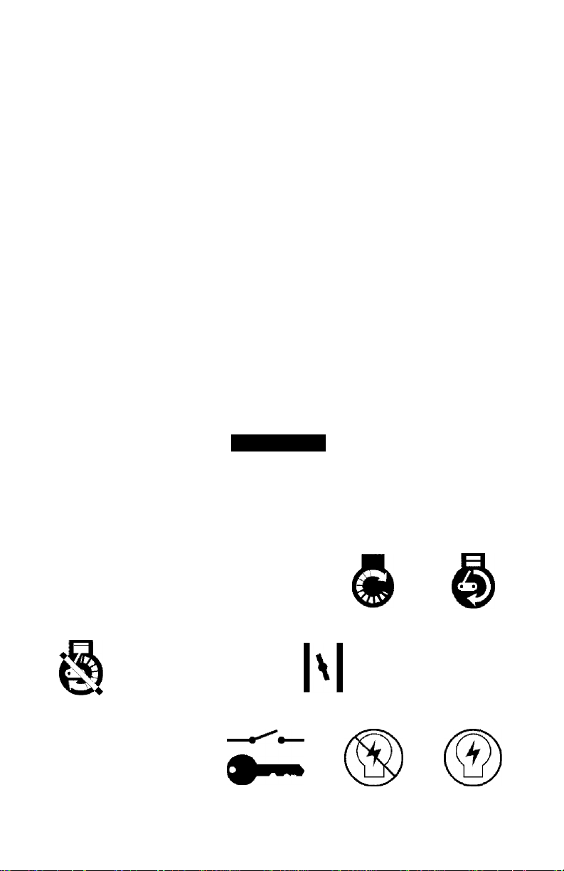
IMPORTANT: Many of the following symbols are located on your snow thrower or on litera
ture supplied with the product. Before you operate the snow thrower, learn and understand
the purpose for each symbol.
CONTROL AND OPERATING SYMBOLS
if ®
Slow Fast
O I
Engine Off Engine Stop On Choke Off Choke On Neutral
Electric Start Engine Start Engine Run
N
M
Throttle Primer Button ignition Key Ignition Off Ignition On
F-0410108L 4
! 5^ ■##■=&.
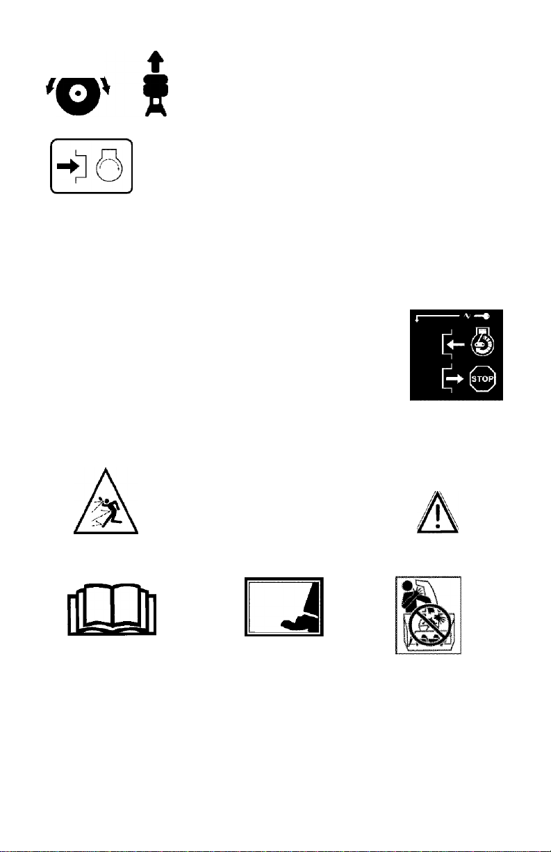
Drive Clutch Forward Reverse Auger Clutch Auger Collector Engage
Push To Engage
Electric Starter
1
Fuel
Oil
a-
é
Discharge DOWN Discharge UP Discharge LEFT Discharge RIGHT
O
Weight Transfer Weight Transfer
Lift Handle To Depress Pedal
Engage To Disengage
Safety Warning Symbols
DANGER
Thrown Objects.
Keep Bystanders Away.
I
Thrown Objects.
Keep Bystanders Away.
Transmission
DANGER
Fuel Oil Mixture
Ignition Key
Insert To Run,
Pull Out To Stop.
WARNING
IMPORTANT
Read Owner’s Manual
Before Operating
This Machine.
WARNING
Hot Surface
F-0410108L
DANGER
Avoid Injury From
Rotating Auger. Keep
Hands, Feet And
cii‘thit^g“Avi^yT Unclogging Discharge Chute!
DANGER
Stop The Engine Before
s
STOP
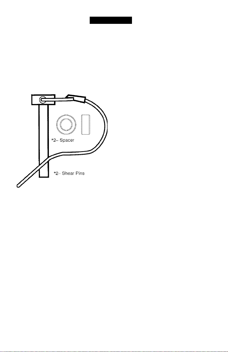
ASSEMBLY
CONTENTS OF PARTS BAG (ACTUAL SIZE)
1 - Ownor’s Manual (not shown)
1 - Packet of Fuel Stabilizer (not shown)
1 - Warranty Card (not shown)
*Non-Assemb!y Parts, found in toolbox located on belt cover
F-0410108L
WARNING: Always wear
A
safety glasses or eye shields
while assembling snow
thrower.
TOOLS REQUIRED FOR
ASSEMBLY
1 - Knife to cut carton
2-1/2 inch wrenches
(or adjustable wrenches)
2-9/16 inch wrenches
(or adjustable wrenches)
2 - 3/4 inch wrenches
(or adjustable wrenches)
1 - Pliers (to spread cotter pin)
1 - Screwdriver
1 - Measuring tape or ruler
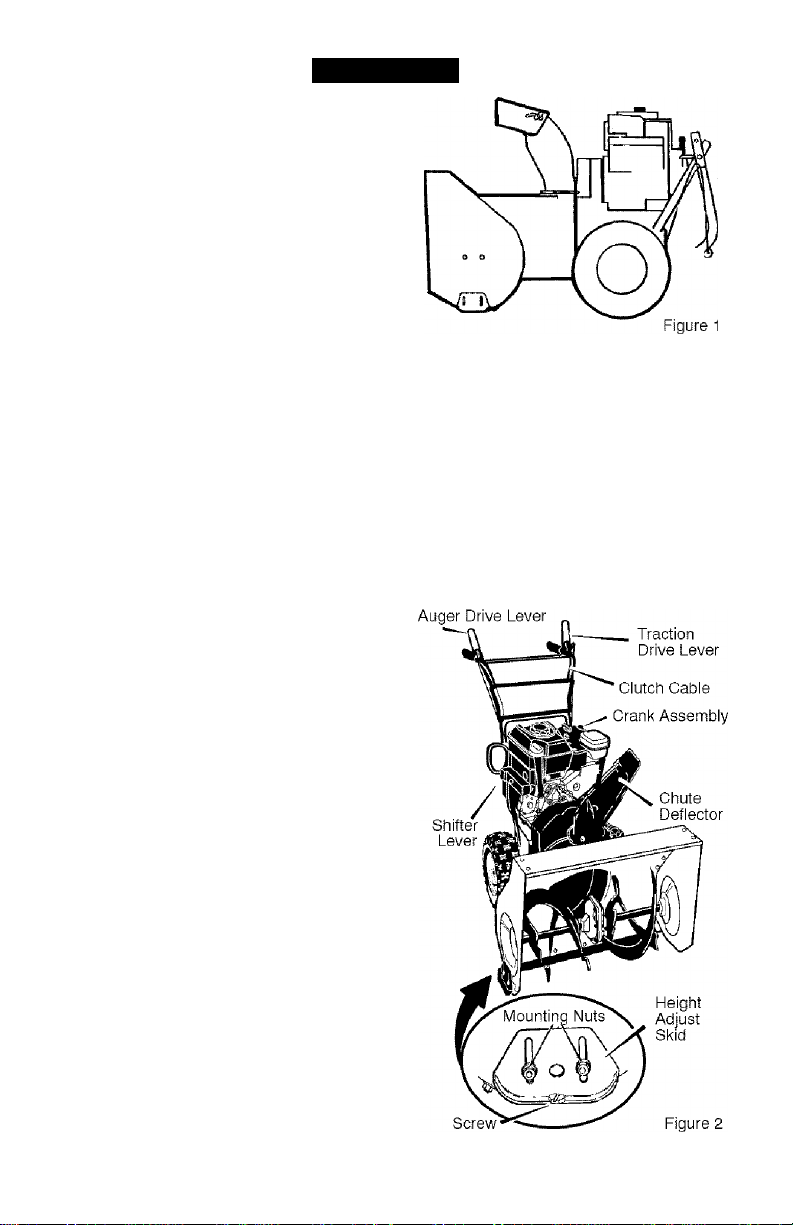
ASSEMBLY
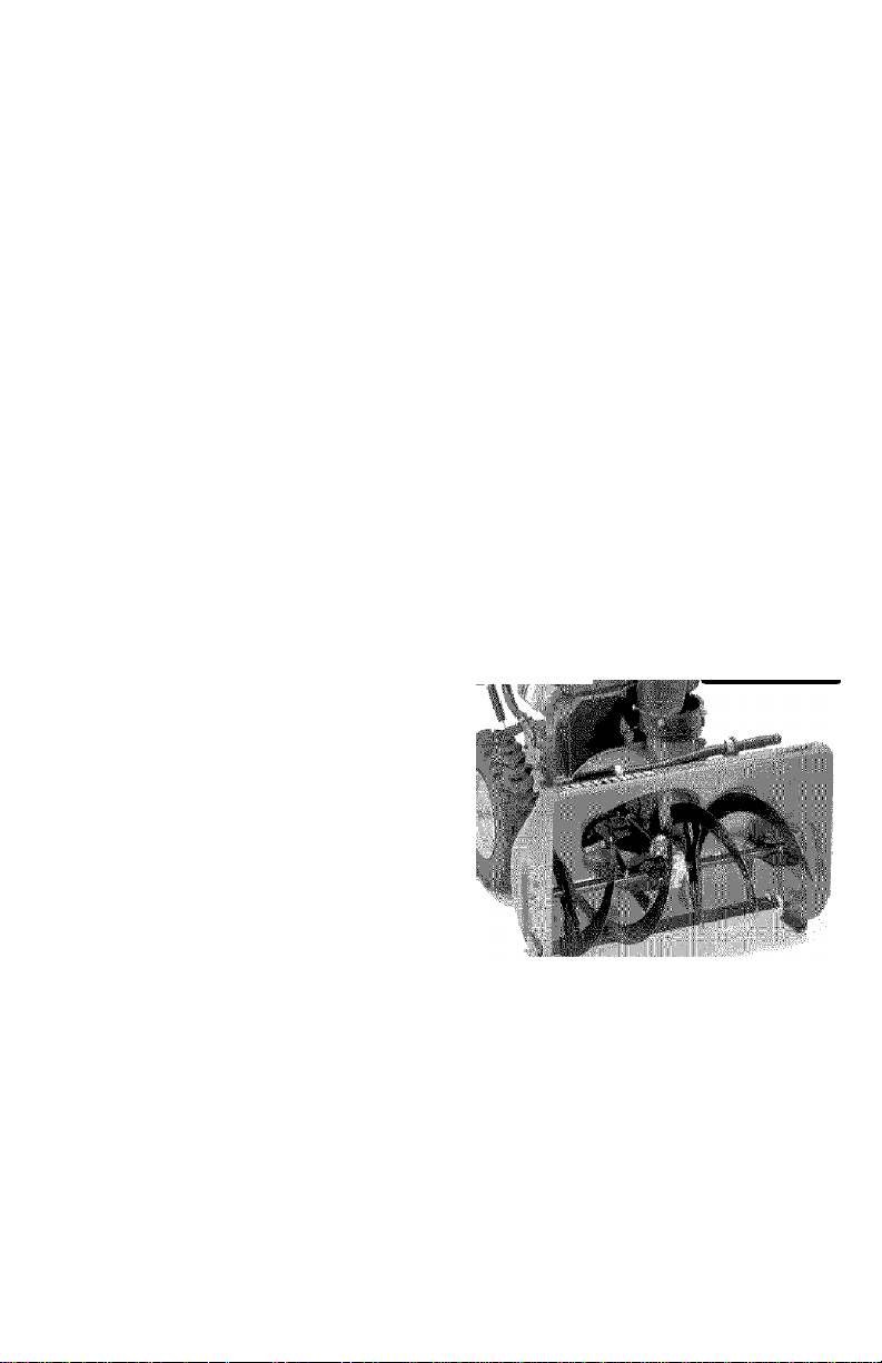
Figure 1 shows the snow thrower in the
shipping position.
Figure 2 shows the snow thrower com
pletely assembled.
References to the right or left hand side
of the snow thrower are from the view
point of the operator’s position behind
the unit.
TO REMOVE SNOW THROWER
FROM CARTON
1. Locate all parts packed separately
and remove from the carton.
NOTE: Place fuel stabilizer in a
safe place until needed for storage.
2. Remove and discard the packing
material from around the snow
thrower.
3. Cut down all four corners of the car
ton and lay the panels flat.
4. Cut the straps that secure the axie
to the pallet.
5. For shipping purposes, the height
adjust skids are attached to the
pallet. Remove the screw that se
cures each height adjust skid to
the pallet. See Figure 2.
6. Roll snow thrower off the pallet by
pulling on the lower handle. CAU
TION; DO NOT back over control
cables.
7. Remove all packing material from
the unit.
8. Cut ties securing the clutch control
cable to the lower handle and lay
F-0410108L
cable back away from the motor
frame.
ASSEMBLY
TO ASSEMBLE THE HANDLE AND
CRANK ASSEMBLY
1. Cut tie holding shift rod to lower
handle and move shifter to the first
forward gear.
2. Cut and discard the plastic tie that
secures the crank assembly.
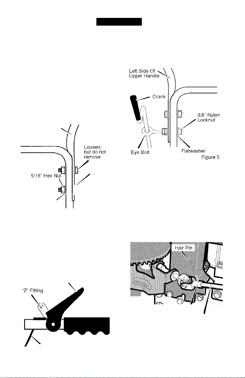
3. Loosen, but do not remove, the
screws, flatwashers, lockwashers,
and hex nuts in the upper holes of
the lower handle. See Figure 3.
4. Remove the fasteners and the eye
bolt from the lower holes of the low
er handle See Figure 5.
Right Hand Side
Of Upper Handle
11/32"
Flatwasher
te / 6”
y / Screw
5/16” Split
Lockwasher
Figure 3
NOTE: Make sure the cables are
not caught between the upper and
lower handle.
5. Raise the upper handle into operat
ing position.
NOTE: If the cables have become dis
connected form the drive levers, rein
stall the cables as shown in Figure 4.
6. Install the fasteners that were re
moved in step 4. DO NOT tighten
until all bolts are in place.
Attach the crank rod to the universa!
joint assembly with the hair pin. See
Figure 6.
Tighten nut on eye bolt. Make sure
eye bolt is properly aligned and the
crank can freely rotate.
Tighten all handle and panel bolts.
F-0410108L
Lever
Universal Joint Assernbly
Crank'Rod
Figure 6
Control Cable Figure 4
ASSEMBLY
NOTE: If the cables have become dis
connected, connect cables as shown in
Figure 7.
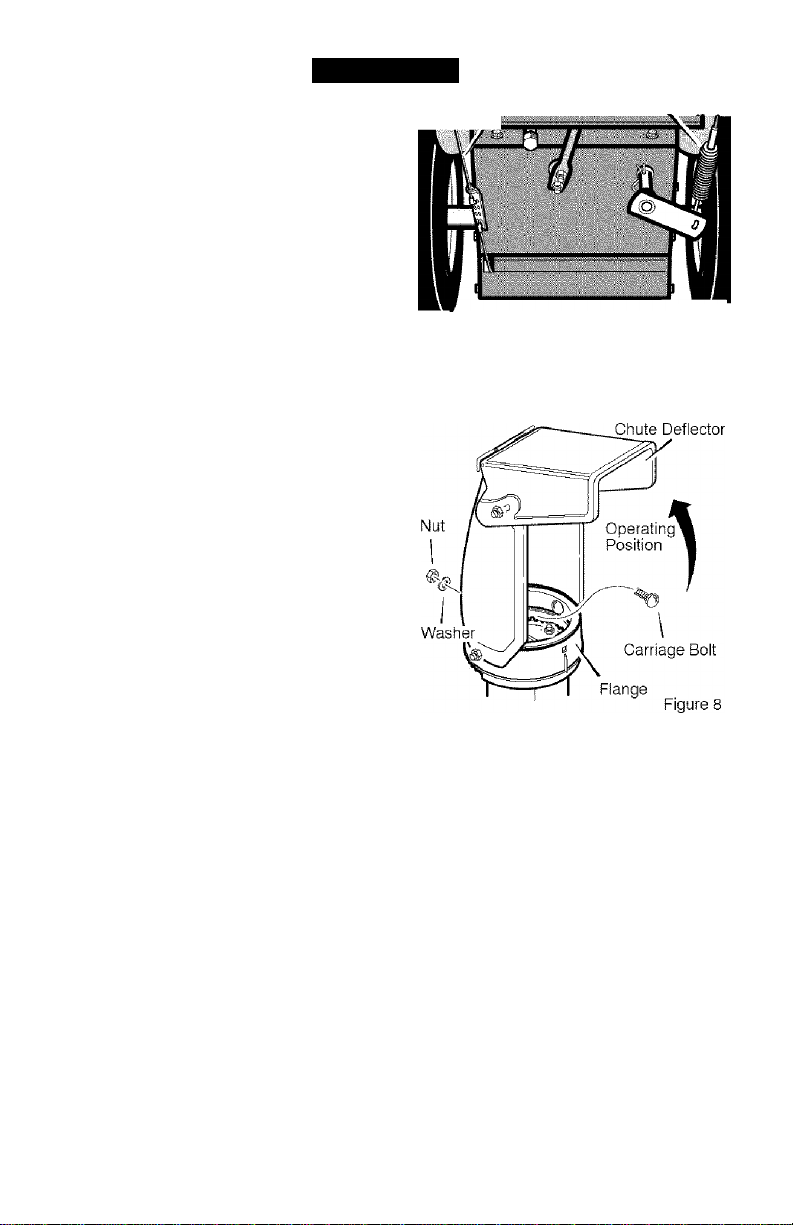
HOW TO ASSEMBLE THE CHUTE DEFLECTOR
1. Remove the carriage bolt. See
Figure 8.
2. Raise the chute deflector into op
erating position,
3. Fasten chute deflector to flange
with carriage bolt. Make sure to
install with head of carriage bolt on
the inside of the flange.
4. Fasten with washer and locknut.
5. Tighten locknut securely.
NOTE: Make sure all carriage
bolts In flange are tight. DO NOT
OVERTIGHTEN.
Traction Drive Cable
Auger Drive Cable
Figure 7
HOW TO SET THE SKID HEIGHT
Your snow thrower is equipped with
height adjust skids on the outside of the
auger housing. To adjust the skid
HOW TO SET THE LENGTH OF THE CABLES
The cables were adjusted at the factory
and no adjustments should be neces
sary. However, after the handles are put
in the operating position, the cables can
F-0410108L
height for different conditions, see To
Adjust Skid Height paragraph in the
Service And Adjustment section.
be too tight or too loose, if an adjust
ment is necessary, see “How To Check
And Adjust The Cables” in the Service
And Adjustment section.

ASSEMBLY
CHECKLIST
Before you operate your new snow
thrower, to ensure that you receive the
best performance and satisfaction from
this quality product, please review the
following checklist:
y" All assembly instructions have been
completed.
y The discharge chute rotates freely.
y No remaining loose parts in carton.
y Check the fasteners. Make sure all
fasteners are tight.
y Check the air pressure of the tires.
Correct air pressure is from 14 to 17
PSI. See the side of the tire for maxi
mum inflation. Do not exceed maxi
mum inflation.
y On electric start models, the unit was
shipped with the starter cord plugged
into the engine. Before operating, un
plug the starter cord from the engine.
While learning how to use your snow
thrower, pay extra attention to the fol
lowing important items:
y Engine oil is at proper level. Use a
high quality detergent oil classified
“For Service SG, SH, SJ, SL, or
higher”.
y Make sure gas tank is filled properly
with clean, fresh, unleaded gasoline
with a minimum of 85 octane.
y Become familiar with all controls-
their location and function. Operate
controls before starting engine.
F-0410108L
10
OPERATION
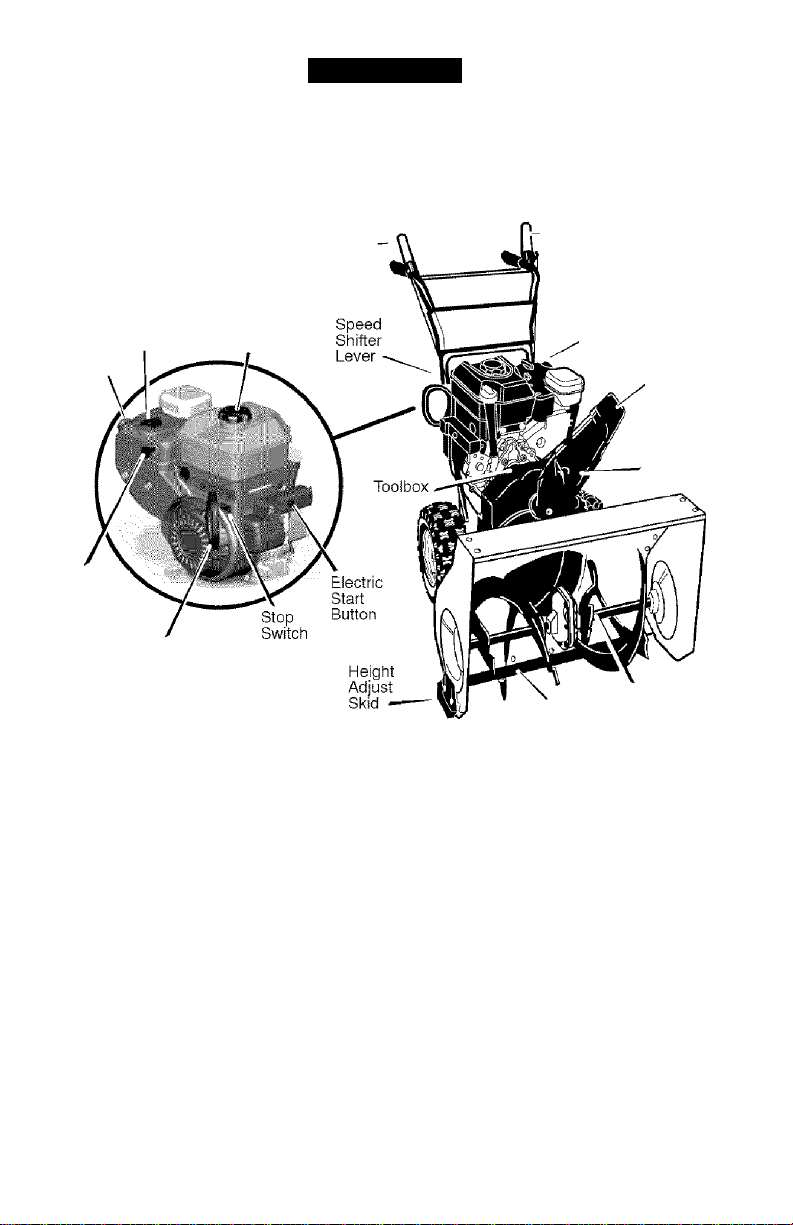
KNOW YOUR SNOW THROWER
READ THIS OWNER’S MANUAL AND SAFETY RULES BEFORE OPERATING
YOUR SNOW THROWER. Oompare the illustrations with your SNOW THROWER
to familiarize yourseif with the location of various controls and adjustments. Save
this manual for future reference.
Auger ——
Drive Lever
(right hand)
Choke
Control Gas
Primer I
Button
Safety
Key
Recoil
Starter
Handle
Auger Drive Lever - Starts and stops
the auger and impeller (snow gathering
and throwing)
Traction Drive Lever - Propels the
snow thrower forward and in reverse.
Speed Shifter Lever - Selects the
speed of the snow thrower {6 speeds for
ward and 2 speeds reverse).
Crank Assembly - Changes the direc
tion of snow throwing through the dis
charge chute.
Chute Deflector - Changes the distance
the snow is thrown.
Discharge Chute - Changes the height
and direction the snow is thrown.
Height Adjust Skid - Adjusts the ground
clearance of the auger housing.
F-0410108L 11
Traction Drive Lever
(left hand)
Crank
Assembly
Chute
Deflector
Discharge
Chute
Scraper Bar
Shear Pin
Figure 9
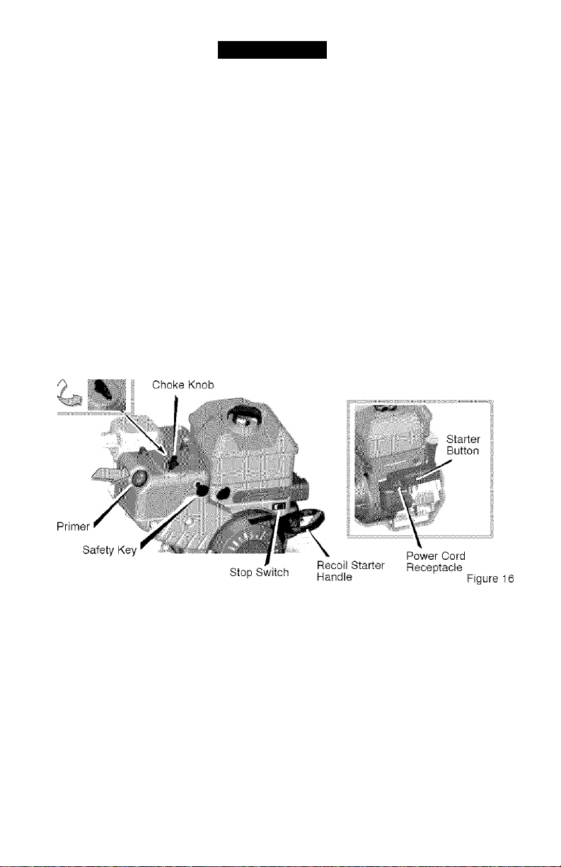
Safety Key - Must push in to start the
engine.
Recoil Starter Handle - Starts the en
gine manually.
Choke Control - Used to start a cold
engine.
Primer Button - Injects fuel directly into
the carburetor manifoid for fast starts in
cold weather.
Electric Start Button - (If so equipped)
Used to start the engine using the 120 V
electric starter.
Shear Pin - Shear pins are designed to
break (to protect the machine) if an ob
ject becomes lodged in the auger hous
ing.
Toolbox - Spare shear pins and spacers
are located in toolbox.
OPERATION
The operation of any snow thrower can
result in foreign objects being thrown
into the eyes, which can result in se
vere eye damage. Always wear safety
glasses or eye shields while operating
the snow thrower.
We recommend standard safety
glasses or a wide vision safety mask for
over your glasses.
WARNING; Read Owner’s
A
charge toward bystanders. Stop the
engine before unclogging discharge
chute or auger housing and before
leaving the machine.
TO STOP YOUR
SNOW THROWER
1. To stop throwing snow, release the
2. To stop the wheels, release the
3. To stop the engine, pul! out the
CAUTION; To stop the engine, do not
move the choke control to CHOKE
position. Backfire or engine damage
can occur.
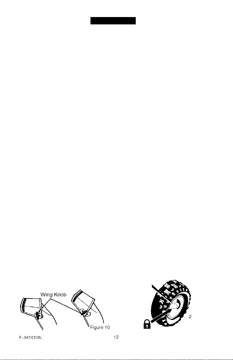
TO CONTROL SNOW DISCHARGE
1. Turn the chute control rod to set the
2. Loosen the wing knob on the chute
Manual before operating
machine. Never direct dis
auger drive lever.
traction drive lever.
safety key
direction of the snow throwing.
deflector and move the deflector to
set the distance. Move the deflector
(Up) for more distance, (Down) for
less distance. Then tighten the
wing knob (See Figure 10).
HOW TO MOVE FORWARD AND
BACKWARD
1. To shift, release the traction drive
lever (left hand) and move the
speed shifter lever to the speed you
desire. Ground speed is deter
mined by snow conditions. Select
the speed you desire by moving the
speed shifter lever left into the ap
propriate notches on the shift lever
plate:
Speeds 1,2 - Wet, Heavy
Speed 3 - Light
Speed 4 - Very Light
Speed 5,6 - Transport only
2. Engage the traction drive lever (left
hand). As the snow thrower starts
to move, maintain a firm hold on the
handles, and guide the snow throw
er along the clearing path. Do not
attempt to push the snow thrower.
3. To move the snow thrower back
ward, move the speed shifter lever
right into first or second reverse and
engage the traction drive lever (left
hand)
IMPORTANT: Do not move the speed
shifter lever while the traction lever is
down,
TO THROW SNOW
1. Push down the auger driver lever
(right hand).
2. Release to stop throwing snow.
TO USE WHEEL LOCKOUT PIN
1. The right hand wheel is secured to
the axle with a klick pin . This unit
was shipped with this klick pin in the
locked position (through wheel
hole). See Figure 11.
Klick Pin
Locked
Position
-Wheel
Drive
Figure 11
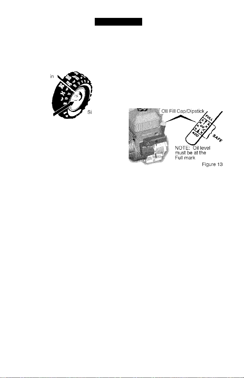
2. For ease of maneuverability in light
snow conditions, disconnect the
klick pin from the wheel locked
position and push into the single
wheel drive position (unlocked axle
hole only). See Figure 12.
Klick P
Unlocked^ ,
Position n
ngle Wheel
Drive
Figure 12
NOTE; Make sure that the klick pin is
in the single wheel drive position of the
axle only and not through the locked
position.
OPERATION
NOTE; Do not check the level of the
oil while the engine runs.
2. Remove the oil fill cap/dipstick and
wipe with a clean cloth.
3. Insert the oil fill cap/dipstick and
turn clockwise to tighten.
4. Remove the oil fill cap/dipstick and
check the oil.
5. If necessary, add oil until the oil
reaches the FULL mark on the oil fill
cap/dipstick (see Figure 13). Do not
add too much oil.
BEFORE STARTING THE ENGINE
1. Before you service or start the en
gine, familiarize yourself with the
snow thrower. Be sure you under
stand the function and location of all
controls.
2. Check the tension of clutch cable
before starting the engine. See To
Adjust The Control Cable para
graph in the Service & Adjust
ments section of this manual.
3. Be sure that all fasteners are tight.
4. Make sure the height adjust skids
are properly adjusted. See To Ad
just Skid Height paragraph in the
Service & Adjustments section of
this manual.
5. Check tire pressure (14-17
pounds). Do not exceed maximum
amount of pressure.
CHECK THE OIL;
NOTE; The engine was shipped from
the factory filled with oil. Check the lev
el of the oil. Add oil as needed.
To Add Oil
1. Make sure the unit is level.
F-0410108L 13
6. Tighten the fill cap/dipstick securely
each time you check the oil level.
NOTE; Synthetic oil can assist with
starting in extreme cold temperatures.
Synthetic 5W30 is acceptable for all
temperatures. DO NOT mix oil with
gasoline.
FILL GAS:
This engine is certified to operate on
gasoline. Exhaust Emission Control
System: EM (Engine Modifications).
WARNING; Alcohol blended
fuels (called gasohol or
A
those using ethanol or
methanol) can attract moisture
which leads to separation and
formation of acids during storage.
Acidic gas can damage the fuel sys
tem of an engine while in storage.
NOTE; To avoid engine problems, the
fuel system must be emptied before
storage for 30 days or longer. Start the
engine and let it run until the fuel lines
and carburetor are empty. Use fresh
fuel next season. See the Storage
section in this manual for additional in
formation.
OPERATION
Never use engine or carburetor cleaner
products in the fuel tank or permanent
damage may occur.
Fill the fuel tank only with a fresh, clean,
unleaded regular, unleaded premium, or
reformulated automotive gasoline with a
minimum of 85 octane.
DO NOT use
leaded gasoline. Make sure that the
container you pour the gasoline from is
clean and free from rust or other foreign
particles. Never use gasoline that may
be stale from long periods of storage in
the container.
WARNING: Gasoline is flam
A
mable. Always use caution
when handling or storing
gasoline.
• Turn engine off and iet engine
cool at least two minutes before
removing the gas cap.
• Do not fill fuel tank while snow
thrower is running, when it is hot,
or when snow thrower is in an en
closed area.
• Keep away from open flame or an
electrical spark and do not smoke
while filling the fuel tank.
TO STOP ENGINE
CAUTION: To stop the engine, do not
move the choke control to CHOKE
position. Backfire or engine damage
can occur.
1. Push the stop switch to the OFF
position.
^ Stop Switch
Figure 14
2. Pull out the safety key.
^ Safety Key
Figure 15
F-0410108L
Never fill the tank completely. Fill
the tank to approximately 1-1/2”
below the top of the tank opening
to provide space for expansion of
fuel.
Always fill fuel tank outdoors and
use a funnel or spout to prevent
spilling.
Make sure to wipe up any spilled
fuel before stating the engine.
Store gasoline in a clean, ap
proved container and keep the
cap in place on the container.
TO START ENGINE
Be sure that the engine oil is at FULL
mark on dipstick. The snow thrower en
gine is equipped with a 120 volt A.C.
electric starter and recoil starter. Before
starting the engine, be certain that you
have read the following information.
If engine floods, set the choke to the
OPEN/RUN position and crank until the
engine starts.
WARNING: Rapid retraction
A
of the starter cord (kick
back) will pull your hand or
arm toward the engine faster than
you can let go of the starter cord.
Broken bones, fractures, bruises, or
sprains could result.
• When starting the engine, slow
ly pull the starter cord until re
sistance Is felt. Then, rapidly
puli the starter cord.
• Before starting the engine, re
move all external equipment/engine loads.
• Make sure components; such as
impellers, pulleys or sprockets,
are securely attached.
14
OPERATION
WARNING: The starter is
A
designed to operate on 120 volt AC
household current. It must be prop
erly grounded at all times to avoid
the possibility of electrical shock
which may be injurious to operator.
• Follow all instructions carefully
• Determine that your house wiring
equipped with a three-wire
power cord and plug and is
as set forth in the “To Start En
gine" section.
is a three-wire grounded system.
Ask a licensed electrician if you
are not sure. If your house wire
system is not a three-wire system,
do not use this electric starter un
der any conditions.
If your system is grounded and a
three-hole receptacle is not avail
able at the point your starter will
normally be used, one should be
installed by a licensed electrician.
When connecting 120 volt AC
“Power Cord”, always connect the
cord to the Switch Box on the en
gine first, then plug the other end
into the three-hole grounded re
ceptacle. When disconnecting
“Power Cord”, always unplug the
end in the three-hole grounded re
ceptacle first.
How To Start A Cold Engine
1. Be sure auger drive and traction
drive levers are in the disengaged
(RELEASED) position.
2. Push the stop switch to the ON
position {see Figure 16).
3. Push in the safety key.
4. Rotate the choke knob to the
CHOKE position.
5. (Electric Start) Plug the power cord
into the starter motor on the en
gine. Plug the other end of power
cord into a three-hole, grounded
120 VOLT, AC receptacle.
F-0410108L 15
Push the primer button as speci
fied below. Remove finger from
primer button between pushes.
• Push two times if temperature is
15° F (-9° 0) or higher.
• Push four times if temperature is
below 15° F (-9° 0).
(Electric Start) Push down on the
starter button until the engine starts.
To prolong the life of the starter, do not
crank for more than 5 seconds at a
time. Wait one minute between starts
to allow the starter motor to cool.
(Recoil Start) Slowly pull the recoi!
starter handle until resistance is

felt and then pull rapidly to start the
engine. Do not allow the recoil
starter handle to snap back. Slowly
return the recoil starter handle.
9. If the engine does not start in 5 or 6
tries, See Difficult Starting in the
“Troubleshooting Table”.
10. Allow the engine to warm up for
several minutes. As the engine
warms up, adjust the choke knob
toward the RUN position. Wait until
the engine runs smoothly before
each choke adjustment.
11. (Electric S tart) First disconnect
power cord from receptacle. Then,
disconnect the power cord from the
starter motor.
How To Start A Warm Engine
If restarting a warm engine after a short
shutdown, leave the choke lever in the
oft position and do not push the primer
button. If the engine fails to start, follow
the Cold Start instructions.
Frozen Starter
If the starter is frozen and will not turn
the engine, follow the steps below.
1. Puli as much starter rope as pos
sible out of the starter.
2. Release the starter handle and let it
snap back against the starter. Re
peat until the engine starts.
Warm engines will cause condensation
in cold weather. To prevent possible
freeze-up of recoil starter and engine
controls, proceed as follows after each
snow removal job.
OPERATION
1. With engine off, allow engine to cool
2. Puli starter rope very slowly until re
3. With the engine not running, wipe all
A
gine exhaust contains CARBON
MONOXIDE, AN ODORLESS AND
DEADLY GAS. Keep hands, feet,
hair and loose clothing away from
any moving parts on engine and
snow thrower.
• Engine parts, especially the muf
* Never allow children to operate
• Keep the area of operation clear
• Never leave the snowthrower un
for several minutes.
sistance is felt, then stop. Allow the
starter rope to recoil. Repeat three
times.
snow and moisture from the carbu
retor cover in area of controls and
levers. Also, move the choke control
and starter handle several times.
WARNING; Never run en
gine indoors or in enclosed,
poorly ventilated areas. En
fler, become extremely hot. Se
vere thermal burns can occur on
contact. Allow the engine to cool
before touching.
the snow thrower. Never allow
adults to operate the snow throw
er without proper instruction.
of all persons, particularly small
children and pets.
attended while the engine is run
ning. Anyone operating the en
gine or equipment must carefully
read and understand the operat
ing instructions.
F-0410108L
16

OPERATION
TO REMOVE SNOW FROM AUGER
WARNING; Do not attempt
A
auger with your hands. Use the
cleaning stick to remove snow or
debris.
A cleaning stick is attached to the top of
the auger housing. Use the cleaning
SNOW THROWING TIPS
1. For maximum snow thrower efficien
2. Most efficient snow throwing is ac
3. For complete snow removal, slightly
4. The snow should be discharged
5. For normal usage, set the skids so
6. On gravel or crushed rock surtaces,
to remove snow or debris
that may become lodged In
cy in removing snow, adjust ground
speed. Go slower in deep, freezing
or wet snow. If the wheels slips, re
duce forward speed.
complished when the snow is re
moved immediately after if falls.
overlap each path previously taken.
down wind whenever possible.
that the scraper bar is 1/8” above
the skids. For extremely hard-
packed snow surfaces, adjust the
skids upward so that the scraper
bar touches the ground.
stick to remove snow from the auger
housing.
• Release auger drive lever.
• Remove (do not turn) safety key.
• Disconnect spark plug wire.
• Do not place your hands in the au
ger or discharge chute. Use the
cleaning stick to remove snow.
set the skids at 1-1 /4” below the
scraper bar. See To Adjust Skid
Height paragraph in the Service &
Adjustments section of this manu
al. Rocks and gravel must not be
picked up and thrown by the ma
chine.
7. After the snow throwing job has
been completed, allow the engine to
idle for a few minutes, which will
melt snow and accumulated ice off
the engine.
8. Clean the snow thrower thoroughly
after each use.
9. Remove ice and snow accumulation
and al! debris from the entire snow
thrower, and flush with water (if pos
sible) to remove ail salt or other
chemicals. Wipe snow thrower dry.
F-0410108L
17

MAINTENANCE
CUSTOMER RESPONSIBILITIES
SERVICE RECORDS
Fill in dates as you
complete regular
Check Engine Oil Level
Change Engine Oil
Ti ghten M Screws and
Nuts
...............................
Check and Clean Spark
Plug
Replace Spark Plug
Clean and Inspect
Spark Arrestor
Lubricate Chute Control
Flange
...........................
Check Fuel
Check Adjustment of
Auger Control Cable
Auger Drive Beit
Check Tire Pressure
* Adjust after 2 to 4 hours of use,
Before
Each
Use
V
Often
Every
8
Hours
V
GENERAL RECOMMENDATIONS
The warranty on this snow thrower does
not cover items that have been subjected
to operator abuse or negligence. To re
ceive full value from the warranty, the op
erator must maintain the snow thrower as
instructed in this manual.
Some adjustments will need to be made
periodically to properly maintain your
snow thrower.
Maintenance, replacement, or repair of the
emission control devices and systems can
be performed by any non-road engine re
pair establishment or individual. Regular
maintenance will improve the performance
and extend the life of the engine.
WARNING; Do not strike the
A
flywheel with a hammer or a
hard opject. If done, the fly
wheel can shatter during operation.
Do not tamper with the governor
spring, links or other parts to in
crease engine speed.
F-0410108L IE
Every
Hours
Every
25
Hours
50
Every
100
Hours
Each
Season
....
AFTER EACH USE
• Run the machine to clear the auger
of snow.
• To prevent freezing of the auger or
controls, remove all snow and slush
from the snow thrower.
• Check for any loose or damaged
parts.
• Tighten any loose fasteners.
• Check and maintain the auger.
• Check controls to make sure they
are functioning properly,
• If any parts are worn or damaged,
replace immediately.
Before
Storage
■V '
MAINTENANCE
ENGINE SPECIFICATIONS
HORSEPOWER
DISPLACEMENT 206 CC
BORE 68mm (2.677 in.)
STROKE 56mm (2.205 in.)
GASOLINE 3 quarts
CAPACITY (unleaded)
OIL CAPACITY
(18 oz capacity)
SPARK PLUG: Champion RJ19LM
VALVE Intake 0.004-0.006 in.
CLEARANCE: Exhaust: 0.009-0.011 in.
ARMATURE
AIR GAP:
S HP
5W30
(Gap .030 in.) or
equivalent
0.010-0.014 in.
POWER RATINGS
The power ratings for an individual
engine model are initially developed by
starting with SAE (Society of Automo
tive Engineers} code J1940 {Small
Engine Power & Torque Rating Proce
dure) (Revision 2002-05). Given both
the wide array of products on which our
engines are placed, and the variety of
environmental issues applicable to
operating the equipment, it may be that
the engine you have purchased will not
develop the rated horsepower when
used in a piece of power equipment
(actual “on-site” power). This difference
is due to a variety of factors including,
but not limited to, the following: differ
ences in altitude, temperature, baro
metric pressure, humidity, fuel, engine
lubrication, maximum governed engine
speed, individual engine to engine
variability, design of the particular piece
of power equipment, the manner in
which the engine is operated, engine
run-in to reduce friction and clean out of
combustion chambers, adjustments to
the valves and carburetor, and other
factors. The power ratings may also be
adjusted based on comparisons to
other similar engines utilized in similar
applications, and will therefore not
necessarily match the values derived
using the foregoing codes.
F-0410108L
SNOW THROWER
AUGER DRIVE BELT
Adjust the auger drive belt after the first
2 to 4 hours of use, again about mid
season and twice each season thereaf
ter (See to “Belt Adjustment” in the
Service and Adjustment section).
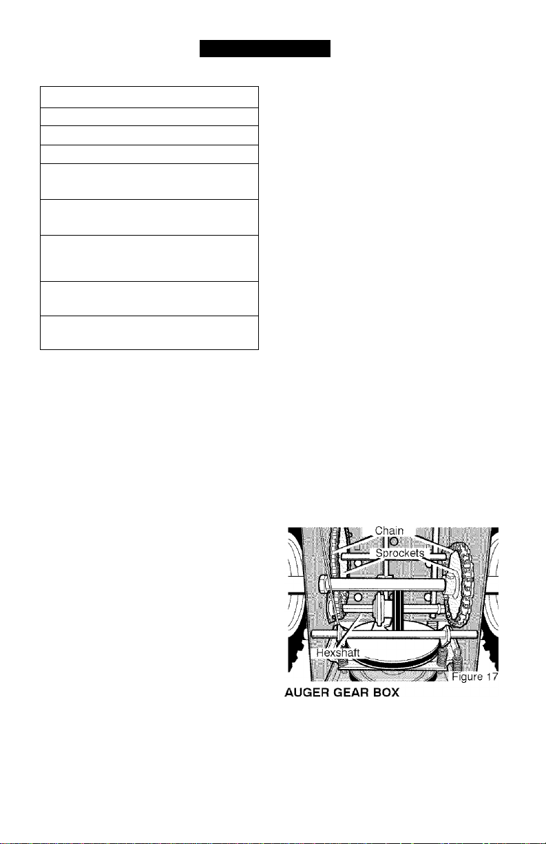
CHAIN LUBRICATION
EVERY 25 HOURS
1. Position speed selector lever in first
(1) forward gear.
2. Stand the snow blower up on the
auger housing end.
NOTE; When the crank case if
filled with oil, do not leave the
snow blower standing up on the
auger housing for an extended
period of time.
3. Remove the bottom panel.
4. Lubricate the chains with a chain
type lubricant.
5. For storage, wipe the hexshaft and
sprockets with 5W30 motor oil.
NOTE: Clean all excess grease or
oil found on the rubber friction
wheel or the disc drive plate.
CAUTION: Do not allow grease or
oil to contact the rubber friction
wheel or the disc drive plate.
6. Install the bottom panel.
The auger gear box is lubricated at the
factory and should not require addition
al lubrication. If for some reason the
lubricant should leak out, have auger
gear case checked by a competent re
pairman.
19
MAINTENANCE
ENGINE
LUBRICATION
Check the crankcase oil level before
starting the engine and after each eight
{8) hours of continuous use. See
Figure 18. Add S.A.E. 5W30 motor oil
as needed. Synthetic 5W30 is accept
able for aii temperatures. Tighten fill
cap/dipstick securely each time you
check the oil level.
Oil Fill Cap/Dipstick
Oil Drain
Plug
■ ,/
Change the oil every fifty (50) hours or
at least once a year if the snow thrower
is not used for fifty (50) hours.
TO CHANGE ENGINE OIL
1. Position the snow thrower so that
the oil drain plug is at the lowest
point on the engine.
2. When the engine is warm, remove
the oil drain piug and the oil fili
cap/dipstick (see Figure IS). Drain
the oil into a suitable container.
3. After draining aii the oil, reinstall the
oil drain plug securely.
4. Fill the engine crankcase with the
recommended motor oil, pouring
slowly. DO NOT OVERFILL. See
“To Add Oil” in the Operation Sec
tion.
NOTE: Oil level niusi be at FULL mark.
Figure 18
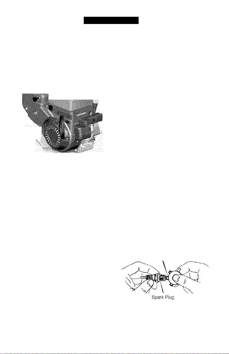
SPARK PLUG
Check the spark plug every twentyfive (25) hours. Replace the spark plug
if the electrodes are pitted or burned, if
the porcelain is cracked, or every 100
hours of use.
1. Make sure the spark plug is clean.
Clean the spark plug by carefully
scraping the electrodes (do not
sand blast or use a wire brush).
2. Check the spark plug gap with a
feeler gauge and reset gap to 0.30”
if necessary. See Figure 19.
3. Before installing the spark plug,
coat the threads lightly with oil for
easy removal. Tighten the spark
plug to a torque of 15 foot-pounds.
Feeler Gauge
0.030”
Figure 19
F-0410108L
20
SERVICE AND ADJUSTMENT
WARNING: Always discon
A
nect the spark plug wire and
place it where it cannot
make contact with spark plug to pre
vent accidental starting when mak
ing any adjustments or repairs.
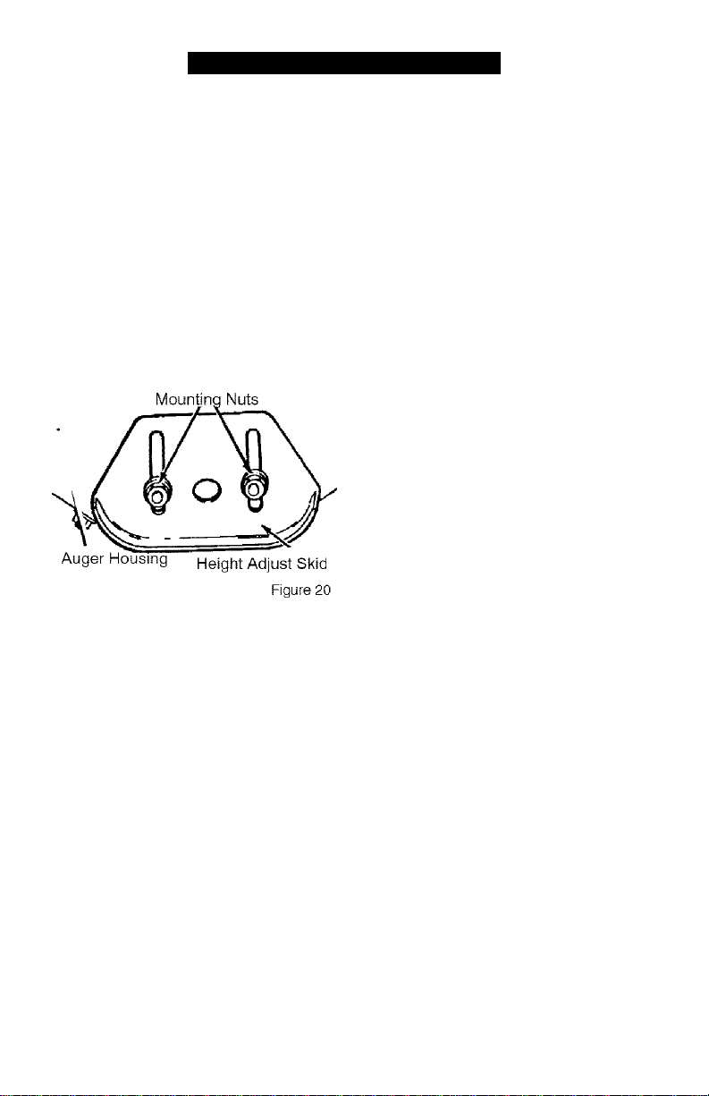
TO ADJUST SKID HEIGHT
This snow thrower is equipped with two
height adjustment skids, located on
the outside of the auger housing. See
Figure 20.
These skids elevate the front of the
snow thrower.
For normal hard surfaces, such as a
paved driveway or walk, adjust the
skids as follows.
1. Position the snow thrower on a level
surface.
2. Make sure both tires are equally in
flated. Proper tire pressure is 14 to
17 PSI. See side of tire for maxi
mum inflation. Do not exceed maxi
mum sidewall pressure on tire.
3. Place the extra shear bolts supplied
with the unit under each end of the
scraper bar next to the adjustable
skids.
4. Loosen the mounting nuts that hold
the adjustable skids. To bring the
front of the snow thrower down,
raise the adjustable skids. Tighten
the mounting nuts. See Figure 20.
NOTE: For rocky or uneven surfaces,
raise the front of the snow thrower by
moving the skids down.
WARNING: Be certain to
A
maintain proper ground
clearance for your particular
area to be cleared. Objects such as
gravel, rocks or other debris, if
struck by the impeller, may be
thrown with sufficient force to cause
personal injury, property damage or
damage to the snow thrower.
TO ADJUST SCRAPER BAR
After considerable use. the metal scrap
er bar will have a definite wear pattern.
The scraper bar in conjunction with the
skids should always be adjusted to al
low 1 /8” between the scraper bar and
the sidewalk or area to be cleaned.
1.
Position the snow thrower on a level
surface.
2.
Make sure both tires are equally in
flated. Proper tire pressure is 14 to
17 PSI. See side of tire for maxi
mum inflation. Do not exceed maxi
mum sidewall pressure on tire.
3.
Loosen the carriage bolts and nuts
securing the scraper bar to the au
ger housing.
4. Adjust the scraper bar to the proper
position.
5.
Tighten the carriage bolts and nuts,
making sure that the scraper bar is
parallel with the working surface.
For extended operation, the scraper
bar may be reversed. If the scraper
bar must be replaced due to wear,
remove the carriage bolts and nuts
and install a new scraper bar.
F-0410108L
21
SERVICE AND ADJUSTMENT
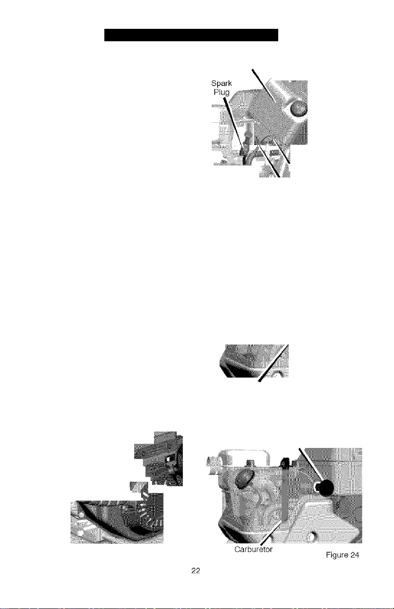
HOW TO REMOVE
THE SNOW HOOD
To access the spark plug, the snow
hood must be removed as follows:
1. Remove the choke control knob
(see Figure 21).
2. Remove the safety key.
3. Remove the mounting screws
(see Figure 22).
4. Slowly remove the snow hood.
Make sure that the primer button
hose and the ignition wire are not
disconnected.
5. The spark plug can now be ac
cessed.
6. To install the snow hood, first make
sure that the primer button hose
and the ignition wire are connected.
7. Mount the snow hood to the engine
and secure with the mounting
screws (see Figure 22).
8. Connect the choke control knob
with the choke shaft on the carbure
tor (see Figure 23 and Figure 24).
Make sure the choke control knob is
properly installed. If the choke con
trol knob is not Installed correctly,
the choke will not operate.
9. Install the safety key.
Mounting Screws
Snow Hood A
JUm
icnitio'h Wire
ittoi
■ M
Choke
Control Knob
PriTer Button -fi
3M Figure 22
'I
Cont'oVkncb
F-0410108L
} ’mg
Figure 21
Choke Shaft
Safety Key
Figure 23
SERVICE AND ADJUSTMENT
BELT ADJUSTMENT
Traction Drive Belt
The traction drive belt has constant
spring pressure and does not require
an adjustment. If the traction drive belt
is slipping, replace the belt. See “How
To Replace The Belts” in the Service
And Adjustment section.
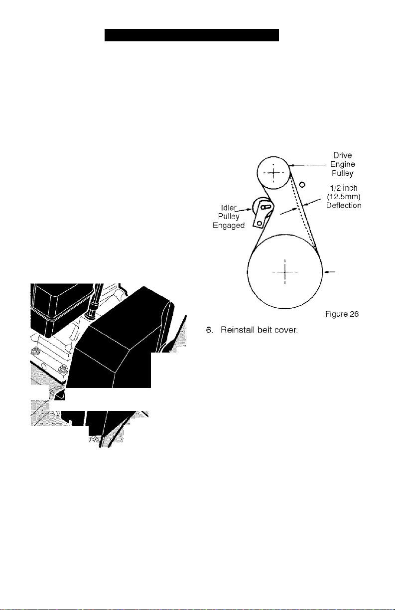
5. Have someone engage auger drive
clutch. Check tension on belt (op
posite idler pulley). Belt should de
flect about 1/2 inch (12.5 mm) with
moderate pressure (Figure 26). You
may have to move idler pulley more
than once to obtain the correct ten-
Auger Drive Belt
If your snow blower will not discharge
snow, check the control cable adjust
ment. If it is correct, then check the
condition of the auger drive belt. If it is
damaged or loose, replace it (see “How
To Replace The Belts” in this section of
the manual).
1. Disconnect spark plug wire,
2. Remove screw from belt cover.
Remove belt cover (see Figure 25).
Belt Cover
. ■' ■ ;■
.
..................... ■■ ■■ ■ ■ ■■ Figu-'e 25 i
Auger
7. Whenever belts are adjusted or re
placed, the cables will need to be
adjusted. (See Cable Adjustment in
this section of the manual).
8. Attach the spark plug wire.
3. Loosen nut on auger idler pulley
and move auger idler pulley towards
belt about 1/8 inch (3 mm) (see
Figure 29).
4. Tighten nut.
F-0410108L
23
SERVICE AND ADJUSTMENT
HOW TO REPLACE THE BELTS
The drive belts are of special construc
tion and must be replaced with original
equipment replacement belts available
from your nearest Sears service center.
Some steps require the assistance of a
second person.
How To Remove the Auger Drive Belt
If the auger drive belt is damaged, the
snow thrower will not discharge snow.
Replace the damaged belt as follows.
1. Disconnect the spark plug wire.
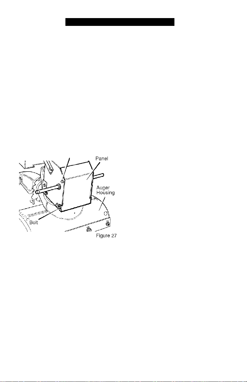
2. Loosen the bolts on each side of
the bottom panel (see Figure 27).
3. Remove the bottom panel.
Bolt
4. Remove screw from belt cover.
Remove the belt cover (see
Figure 25).
5. Loosen the belt guide. Pull the belt
guide away from the auger drive
pulley (see Figure 29).
6. Puli the idler pulley away from the
auger drive belt and slip the auger
drive belt off of the idler pulley.
7. Remove the auger drive belt from
the engine pulley. To remove the
auger drive belt, the engine pulley
may have to be partially rotated.
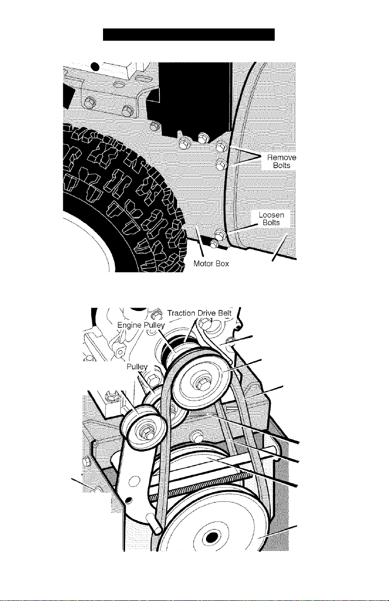
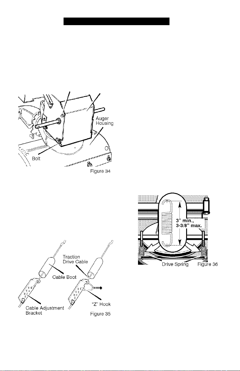
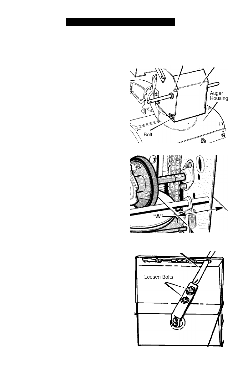
8. Remove the top four bolts that hold
together the auger housing and
the motor box. Loosen the bottom
F-0410108L
Bottom
two bolts. The auger housing and
the motor box can now be split
apart for removal of the belt (see
Figure 28).
9. Remove the old auger drive belt
from the auger drive pulley . Re
place the auger drive belt with an
original factory replacement belt
available from an authorized service
center (see Figure 29).
10. Install the new auger drive belt
onto the auger drive pulley.
NOTE: To assemble the auger
housing to the motor box, have
someone hold the auger clutch
lever in the ENGAGED position.
This will move the idler arm and
pulley enough to allow the auger
drive pulley to move back into
position.
11. Assemble the auger housing to the
motor box with the four bolts that
were removed in step 8. Tighten the
bottom two bolts.
12. Install the auger drive belt onto the
engine pulley.
13. Slip the auger drive belt under the
Idler pulley.
14. Adjust the auger drive belt. See
“How To Adjust The Auger Drive
Belt” in the Service And Adjustment
section.
15. Adjust the belt guide. See “How To
Adjust The Belt Guide” in the Ser
vice And Adjustment section.
16. Install the belt cover. Tighten
screw (See Figure 25).
17. Check the adjustment of the cables.
See “How To Check And Adjust The
Cables” in the Service And Adjust
ment section.
18. Install the bottom panel (see
Figure 27).
19. Tighten the bolts on each side of
the bottom panel.
20. Connect the spark plug wire.
24
SERVICE AND ADJUSTMENT
Auger
Housing
Figure 28
Traction Drive Idler
E-Ring
Swing Plate
Axle Rod ^
F-0410108L
Auger |(j|er Pulley
Beit Guide
Auger Drive Pulley
Auger Drive Belt
Traction Drive
Spring
Traction
Drive Belt
Traction
Drive Pulley
V
25
Engine
Pulley
Figure 29
SERVICE AND ADJUSTMENT
How To Remove
The Traction Drive Belt
If the snow thrower will not move for
ward, check the traction drive belt for
wear or damage. If the traction drive
belt is worn or damaged, replace the
belt as follows.
1. Disconnect the spark plug wire.
2. Remove the auger drive belt. See
“How To Remove The Auger Drive
Belt" in the Service And Adjustment
section.
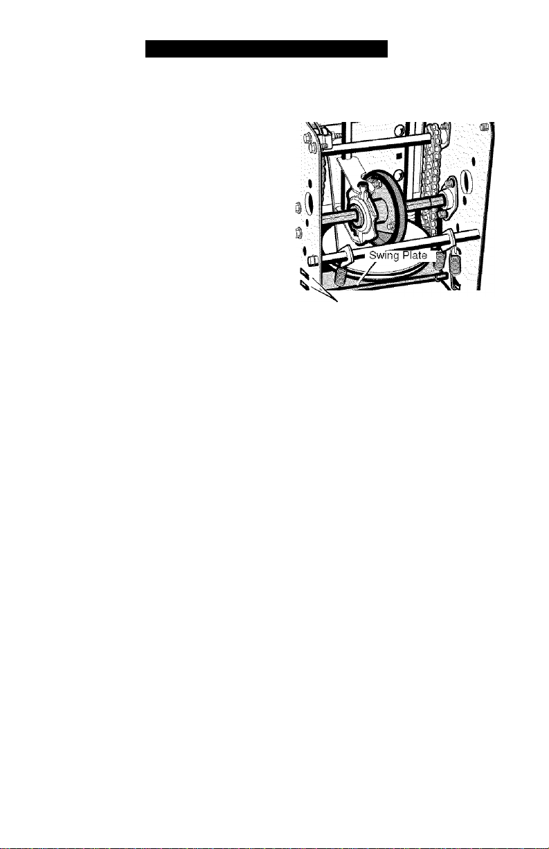
plate is properly secured (see
Figure 30).
3. Remove the e-ring from one end of
the swing plate axle rod. Remove
the swing plate axle rod to allow
the swing plate to pivot forward (see
Figure 29).
4. Remove the traction drive spring.
5. Remove the old traction drive belt
from the traction drive pulley and
from the engine pulley. Replace
the traction drive belt with an origi
nal equipment replacement belt
available from a Sears service cen
ter.
6. Install the new traction drive belt
onto the traction drive pulley and
onto engine pulley.
7. Make sure the traction drive idler
pulley is properly aligned with the
traction drive belt.
8. Attach the traction drive spring.
9. Install the swing plate axle rod and
secure with the e-ring removed
earlier.
10. The bottom of the swing plate must
be positioned between the align
ment tabs. Make sure the swing
F-0410108L
Alignment Tabs
NOTE; If the drive will not engage
after the traction drive belt has
been replaced, then check to
make sure that the swing plate is
positioned between the align
ment tabs.
11. Install and adjust the auger drive
belt. See “How To Remove The Au
ger Drive Belt” in the Service And
Adjustment section.
12. Adjust the belt guide. See “How To
Adjust The Belt Guide” in the Ser
vice And Adjustment section.
13. Install the bottom panel (see
Figure 27).
14. Tighten the bolts on each side of
the bottom panel.
15. Install the belt cover. Tighten
screw (see Figure 25).
16. Check the adjustment of the cables.
See “How To Check And Adjust The
Cables” in the Service And Adjust
ment section.
17. Connect the spark plug wire.
26
Figure 30
SERVICE AND ADJUSTMENT
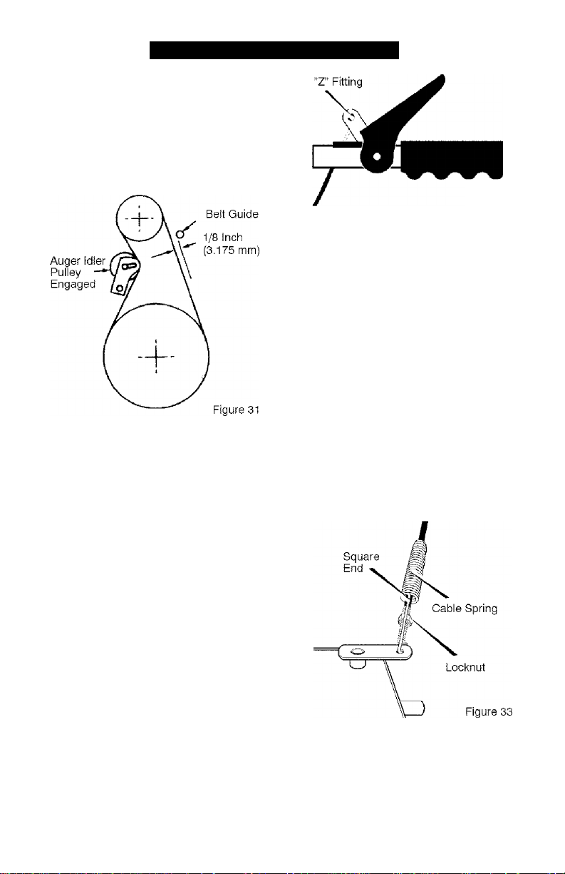
BELT GUIDE ADJUSTMENT
1. Remove spark plug wire.
2. Have someone engage auger drive.
3. Measure the distance between the
belt guide and belt. The distance
should be 1/8 inch (3.175 mm) for
guide. See Figure 31.
if adjustment is necessary, loosen
belt guide mounting bolt. Move belt
guide to the correct position. Tight
en mounting bolt.
Reinstall belt cover.
Reconnect spark plug wire.
Figure 32
2. The center of the “Z” fitting should
be between the center and top of
the hole in the ciutch lever. Adjust
either the auger drive cable or the
traction drive cable as as necessary
according to the following instruc
tions.
Auger Drive Cable Adjustment
1. Run the engine until the fuel tank is
empty and the engine stops.
2. Stand the snow thrower up on the
front end of the auger housing.
3. Push cable through spring to ex
pose the threaded portion of the
cable (see Figure 33).
HOW TO CHECK AND ADJUST THE CABLES
The cables are adjusted at the factory
and no adjustment should be neces
sary. If the cables have become
stretched or are sagging adjustment will
be necessary.
Whenever belts are adjusted or re
placed, the cables will need to be ad
justed.
To check for correct adjustment, un
hook “Z” fitting at clutch lever (see
Figure 32).
1. Move clutch lever to the full forward
position {just contacting plastic
bumper). Holding cable tight, note
position of fitting to hole in clutch le
ver.
F-0410108L
Hold square end of threaded portion
with pliers and adjust locknut in or
out until correct adjustment is
reached. Puli cable back through
spring and connect cable.
27
SERVICE AND ADJUSTMENT
TRACTION DRIVE CABLE ADJUSTMENT
Run the engine until the fuel tank is
empty and the engine stops.
Stand the snow thrower up on the
front end of the auger housing.
Loosen the bolts on each side of
the bottom panel (see Figure 34).
Bolt Bottom Panel
4. Remove the bottom panel.
5. Disconnect the “Z” fitting from the
drive lever (see Figure 32).
6. Slide the cable boot off the cable
adjustment bracket (see
Figure 35).
7. Push the bottom of the traction
drive cable through the cable ad
justment bracket until the “Z"
hook can be removed.
8. Remove the “Z” hook from the
cable adjustment bracket. Move
the “Z” hook down to the next ad
justment hole.
9. Pull the traction drive cable up
through the cable adjustment
bracket.
10. Put the cable boot over the cable
adjustment bracket.
11. Install the “Z” hook to the traction
drive lever (see Figure 32).
12. To check the adjustment, depress
the drive lever and check the length
of one of the drive springs. In cor
rect adjustment, the length of the
drive spring Is;
minimum 3” (76 mm.)
maximum 3-3/8” (85 mm.)
(see Figure 36).
F-0410108L
28
SERVICE AND ADJUSTMENT
HOW TO ADJUST OR REPLACE
THE FRICTION WHEEL
How To Check The Friction Wheei
If the snow thrower will not move for
ward, check the traction drive belt, the
traction drive cable or the friction wheel.
If the friction wheei is worn or damaged,
it must be replaced. See “How To Re
place the Friction Wheel” in this section.
If the friction wheel is not worn or dam
aged, check as follows.
1. Run the engine until the fuel tank is
empty and the engine stops.
2. Stand the snow thrower up on the
front end of the auger housing
(see Figure 37).
3. Disconnect the spark plug wire.
4. Loosen the bolts on each side of
the bottom panel (see Figure 37).
5. Remove the bottom panel.
6. Position the shift speed lever in
the lowest forward speed.
7. Note the position of the friction
wheel (see Figure 38). The correct
distance “A” from the right side of
the friction wheel to the outside of
the motorbox is as follows:
Tire Size Distance “A”
12 and 13 inch 4-1/8”
16 inch 4-5/16”
If the friction wheel is not in the
correct position, adjust according to
the following instructions.
5. Install the bottom panel (see
Figure 37).
6. Tighten the bolts on each side of
the bottom panel.
Bolt Bottom Panel
Figure 37
Figure 38
Speed Control Rod
How To Adjust The Friction Wheel
1. Position the shift speed lever in
the lowest forward speed.
2. Loosen the bolts on the speed
control rod (see Figure 39).
3. Move the friction wheel to the cor
rect position (see Figure 38),
4. Tighten the bolts on the speed
control rod (see Figure 39).
F-0410108L
Figure 39
29
SERVICE AND ADJUSTMENT
How To Replace The Friction Wheel
If the friction wheei is worn or damaged,
the snow thrower will not move forward.
The friction wheei must be replaced as
follows.
1. Run the engine until the fuel tank is
empty and the engine stops.
2. Stand the snow thrower up on the
front end of the auger housing (4),
(see Figure 37).
3. Disconnect the spark plug wire.
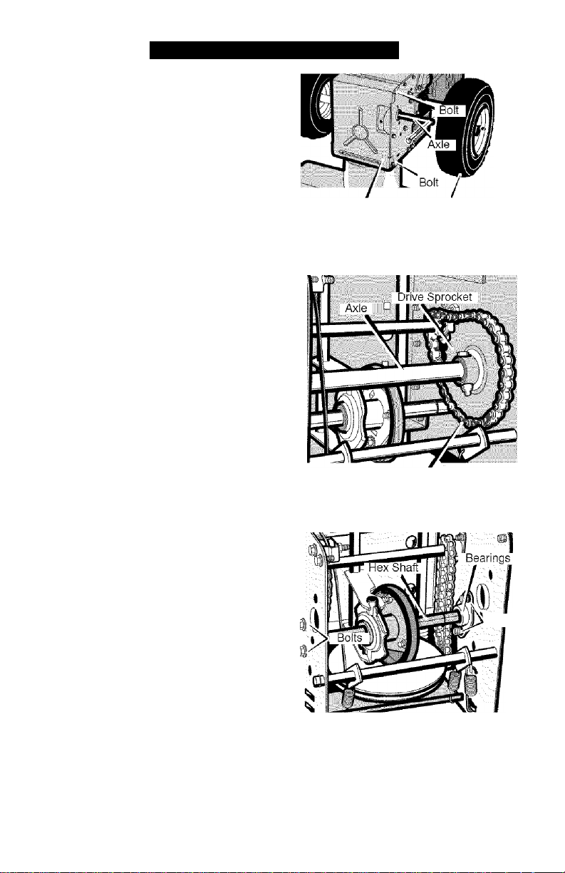
4. Remove the fasteners that secure
the right wheel. Remove the right
wheel from the axle (see Figure 40)
5. Loosen the bolts on each side of
the bottom panel,
6. Remove the bottom panel.
7. Remove the fasteners that secure
the drive sprocket to the axle (see
Figure 41).
8. Remove the left wheel, axle, and
drive sprocket.
Bottom Pane! Wheel
Chain
Figure 40
Figure 41
9. Remove the four bolts that hold the
bearings on each side of the hex
shaft (see Figure 42).
10. Remove the hex shaft and bear
ings.
NOTE: Take special note of the posi
tion of the washers on the hex shaft.
F-0410108L
Bolts
Figure 42
30

SERVICE AND ADJUSTMENT
11. Remove the three fasteners that
hold the friction wheel to the hub
(see Figure 43).
12. Remove the friction wheel from the
hub. Slip the friction wheel oft the
hex shaft.
13. Assemble the new friction wheel
onto hub with the fasteners re
moved earlier.
14. Install the hex shaft and bearings
with the four bolts removed earlier
(see Figure 44).
Make sure the washers are prop
erly installed in the original posi
tion. Also, make sure the two
washers are properly aligned
with the actuator arms.
15. Make sure the hex shaft turns free
ly-
16. Install the left wheel, axle, and
drive sprocket with the fasteners
removed earlier. Install the chain
onto the drive sprocket (see
Figure 41).
17. Check the adjustment of the friction
wheel. See “How To Adjust The
Friction Wheel” in this section.
18. Make sure the friction wheel and the
disc drive plate are free from grease
or oil.
19. Install the bottom panel (see
Figure 40).
20. Tighten the bolts on each side of
the bottom panel.
21. Install the right wheel to the axle
with the fasteners removed earlier.
22. Connect the spark plug wire.
F-0410108L
Washer
Washer
Figure 44

SERVICE AND ADJUSTMENT
HOW TO REPLACE
THE AUGER SHEAR BOLT
The augers are secured to the auger
shaft with special shear bolts. These
shear bolts are designed to break and
protect the machine if an object be
comes lodged in the auger housing. Do
not use a harder bolt as the protection
provided by the shear bolt will be lost.
WARNING; For safety and to
A
shear boits.
protect the machine, use
only original equipment
To replace a broken shear bolt, proceed
as follows. Extra shear bolts were pro
vided with the unit.
1.
Stop the engine. Disengage all con
trols.
2.
Disconnect the spark plug wire.
Make sure all moving parts have
stopped.
3.
Align the hole in the auger with the
hole in the auger shaft. Install the
new shear pin and spacer. See
Figure 45.
Connect the spark plug wire.
F-0410108L
Figure 45
32

STORAGE
WARNING; Never store your
A
snow thrower with gasoline
in the fuel tank indoors or in
an enclosed, poorly ventilated area.
If gasoline remains in the tank,
fumes may reach an open flame,
spark or pilot light from a furnace,
water heater, clothes dryer, ciga
rette, etc.
To prevent damage (if snow thrower is
not used for more than 30 days) follow
the steps below.
SNOW THROWER
1. Thoroughly clean the snow thrower.
2. Lubricate all lubrication points. See
the Maintenance section.
3. Be sure that all nuts, bolts and
screws are securely fastened. In
spect all visible moving parts for
damage, breakage and wear. Re
place if necessary.
4. Touch up all rusted or chipped paint
surfaces; sand lightly before paint
ing.
5. Cover the bare metal parts of the
blower housing auger and the im
peller with rust preventative, such
as a spray lubricant.
NOTE: A yearly checkup or tune-up by
a Sears service center is a good way ot
ensuring that your snow thrower will
provide maximum performance for the
next season.
ENGINE
Gasoline must be removed or treated to
prevent gum deposits from forming in
the fuel tank, filter, hose, and carburetor
during storage. Also, during storage al
cohol blended gasoline that uses etha
nol or methanol (sometimes called
gasohol) attracts water. It acts on the
gasoline to form acids which damage
the engine.
1. Run the engine until the fuel tank is
empty and the engine stops.
2. If you do not remove the gasoline,
use fuel stabilizer supplied with unit
or purchase Craftsman Fuel Stabi
lizer No. 3550. Add fuel stabilizer to
any gasoline left in the tank to mini
mize gum deposits and acids. If the
fuel tank is almost empty, mix stabi
lizer with fresh gasoline in a sepa
rate container and add some to the
fuel tank.
3. Always foliow the instructions on the
stabilizer container. After the stabi
lizer is added to the fuel tank, run
the engine at least ten minutes to
allow the mixture to reach the car
buretor.
4. Change the engine oil.
5. Remove the spark plug and pour
about 15 ml (1 /2 oz) of engine oil
into the cylinder. Replace the spark
plug and crank slowly to distribute
the oil.
6. Store in a clean and dry area, but
NOT near a stove, furnace or water
heater which uses a pilot light or
any device that can create a spark.
OTHER
1. If possible, store your snow thrower
indoors and cover it to give protec
tion from dust and dirt.
2. If the snow thrower must be stored
outdoors, put the snow thrower on
blocks to raise it off of the ground.
3. Cover the snow thrower with a suit
able protective cover that does not
retain moisture. Do not use plastic.
IMPORTANT: Never cover snow
thrower while engine and exhaust areas
are still warm.
F-0410108L
33

TROUBLESHOOTING
TROUBLE CAUSE CORRECTION
Difficult starting Defective spark plug. Replace spark plug.
Water or dirt in fuel system. Remove fuel from fue! tank.
Add fresh fuel.
Engine runs erratically Blocked fuel line, empty gas
tank, or stale gasoline
Engine stalls Unit running on CHOKE. Set choke lever to OFF
Clean fue! line; check fuel
supply; add fresh gasoline
position.
Engine runs erratic;
Loss of power
Excessive vibration Loose parts: damaged
Water or dirt in fue! system. Remove fuel from fue! tank.
Add fresh fue!.
Immediately stop engine.
impeller
Remove ignition key. Tighten
all fasteners and make all
necessary repairs. If
vibration continues, take the
unit to a Sears service
center.
Unit fails to propel itself Traction drive belt loose or
Replace traction drive belt.
damaged.
Incorrect adjustment of
Adjust traction drive cable.
traction drive cable
Worn or damaged friction
Replace friction wheel.
wheel.
Unit falls to discharge
snow
Auger drive belt loose or
damaged.
Auger control cable not
Adjust auger drive belt;
replace if damaged.
Adjust auger control cable.
adjusted correctly.
F-0410108L
Shear bolt broken Replace shear bolt
Discharge chute clogged. Stop engine immediately and
disconnect spark plug wire.
Clean discharge chute and
inside of auger housing.
Foreign object lodged in
auger
Stop engine immediately and
disconnect spark plug wire.
Remove object from auger.
34

(This page applicable in the U.S.A. and Canada only.)
Sears, Roebuck and Co,, U.S.A. (Sears), the California Air Resources Board
(CARB) and the United States Environmental Protection Agency (U.S. EPA)
Emission Control System Warranty Statement (Owner’s Defect Warranty
Rights and Obligations)
EMISSION CONTROL WARRANTY COVERAGE IS APPLICABLE TO CERTIFIED
ENGINES PURCHASED IN CALIFORNIA IN 1995 AND THEREAFTER. WHICH ARE
USED IN CALIFORNIA, AND TO CERTIFIED MODEL YEAR 1997 AND LATER EN
GINES WHICH ARE PURCHASED AND USED ELSEWHERE IN THE UNITED
STATES (AND AFTER JANUARY 1. 2001 IN CANADA).
California and United States Emission Control Defects Warranty Statement
The California Air Resources Board
(CARS), U.S. EPA and Sears are pleased
to explain the Emission Control System
Warranty on your model year 2000 and lat
er small off-road engine (SORE). In Califor
nia, new small off-road engines must be
designed, built and equipped to meet the
State's stringent anti-smog standards.
Elsewhere in the United States, new non
road, spark-ignition engines certified for
model year 1997 and later must meet simi
lar standards set forth by the U.S. EPA.
Sears must warrant the emission control
system on your engine for the periods of
time listed below, provided there has been
no abuse, neglect or improper mainte
nance of your small off-road engine.
Your emission control system Includes
parts such as the carburetor, air cleaner,
ignition system, muffler and catalytic con
verter. Also included may be connectors
and other emission related assemblies.
Where a warrantable condition exists.
Sears will repair your small off-road en
gine at no cost to you including diagnosis,
parts and labor.
Sears Emission Controi Defects Warranty Coverage
Small off-road engines are warranted rel- sions set forth below. If any covered part
ative to emission control parts defects for on your engine is defective, the part will
a period of two years, subject to provi- be repaired or replaced by Sears.
Owner’s Warranty Responsibilities
As the small off-road engine owner, you
are responsible for the performance of
the required maintenance listed in your
Operating and Maintenance Instructions.
Sears recommends that you retain all
your receipts covering maintenance on
your small off-road engine, but Sears
cannot deny warranty solely for the lack
of receipts or for your failure to ensure the
performance of all scheduled mainte
nance.
As the small off-road engine owner, you
should however be aware that Sears may
deny you warranty coverage if your small
off-road engine or a part has failed due to
abuse, neglect, improper maintenance or
unapproved modifications.
You are responsible for presenting your
small off-road engine to an Authorized
Sears Service Dealer as soon as a prob
lem exists. The undisputed warranty re
pairs should be completed in a
reasonable amount of time, not to exceed
30 days.
If you have any questions regarding your
warranty rights and responsibilities, you
should contact a Sears Service Repre
sentative at 1-800-469-4663.
The emission warranty is a defects war
ranty. Defects are judged on normal en
gine performance. The warranty is not
related to an in-use emission test.
Sears Emission Control Defects Warranty Provisions
The following are specific provisions relative to your Emission Control Defects Warranty
Coverage. It is in addition to the Sears engine warranty for non-regulated engines found
in the Operating and Maintenance Instructions.
F-0410108L 35

1. Warranted Parts
Coverage under this warranty ex
tends only to the parts listed below
(the emission control systems
parts) to the extent these parts
were present on the engine pur
chased.
a. Fuel Metering System
• Cold start enrichment sys
tem
• Carburetor and internal
parts
• Fuel Pump
b. Air Induction System
• Air cleaner
Intake manifold
c. Ignition System
• Spark piug(s)
• Magneto ignition system
d. Catalyst System
• Catalytic converter
• Exhaust manifold
• Air injection system or
pulse valve
e. Miscellaneous Items Used in
Above Systems
• Vacuum, temperature,
position, time sensitive valves
and switches
• Connectors and assem
blies
2. Length of Coverage
Sears warrants to the initial owner
and each subsequent purchaser that
the Warranted Parts shall be free
from defects in materials and work
manship which caused the failure of
the Warranted Parts for a period of
two years from the date the engine
is delivered to a retail purchaser.
3. No Charge
Repair or replacement of any War
ranted Part will be performed at no
charge to the owner, including diag
nostic labor which leads to the de
termination that a Warranted Part is
defective, if the diagnostic work is
performed at an Authorized Sears
Service Dealer. For emissions war
ranty service contact your nearest
Authorized Sears Service Dealer as
listed in the “Yellow Pages” under
“Engines, Gasoline,” “Gasoline En
gines,” “Lawn Mowers,” or similar
category.
4. Claims and Coverage Exclusions
Warranty claims shall be filed in ac
cordance with the provisions of the
Sears Engine Warranty Policy. War
ranty coverage shall be excluded
for failures of Warranted Parts
which are not original Sears parts
or because of abuse, neglect or im
proper maintenance as set forth in
the Sears Engine Warranty Policy.
Sears is not liable to cover failures
of Warranted Parts caused by the
use of add-on, non-original, or mo
dified parts.
5. Maintenance
Any Warranted Part which is not
scheduled for replacement as re
quired maintenance or which is
scheduled only for regular inspection
to the effect of “repair or replace as
necessary” shall be warranted as to
defects for the warranty period. Any
Warranted Part which is scheduled
for replacement as required mainte
nance shall be warranted as to de
fects only for the period of time up to
the first scheduled replacement for
that part. Any replacement part that
is equivalent in performance and du
rability may be used in the perfor
mance of any maintenance or
repairs. The owner is responsible for
the performance of all required
maintenance, as defined in the
Sears Operating and Maintenance
Instructions.
6. Consequential Coverage
Coverage hereunder shall extend to
the failure of any engine compo
nents caused by the failure of any
Warranted Part still under warranty.
In the USA and Canada, a 24 hour hot line, 1-800-469-4663, has a menu of pre-re
corded messages offering you engine maintenance information.
F-0410108L
36

Look For Relevant Emissions Durability Period and Air
Index Information On Your Engine Emissions Label
Engines that are certified to meet the California Air Resources Board (GARB) Tier 2
Emission Standards must display information regarding the Emissions Durability Pe
riod and the Air Index, Sears, Roebuck and Co,, U.S,A, makes this information avail
able to the consumer on our emission labels.
The Emissions Durability Period describes the number of hours of actual running
time for which the engine is certified to be emissions compliant, assuming proper
maintenance in accordance with the Operating & Maintenance Instructions, The fol
lowing categories are used:
Moderate; Engine is certified to be emission compliant for 125 hours of actual
engine running time.
Intermediate: Engine is certified to be emission compliant for 250 hours of actual
engine running time.
Extended: Engine is certified to be emission compliant for 500 hours of actual
engine running time.
For example, a typical walk-behind lawn mower is used 20 to 25 hours per year.
Therefore, the Emissions Durability Period of an engine with an intermediate
rating would equate to 10 to 12 years.
The Air Index is a calculated number describing the relative level of emissions for a
specific engine family. The lower the Air index, the cleaner the engine. This informa
tion is displayed in graphical form on the emissions label.
After July 1, 2000, Look For Emissions Compliance
Period OnEngine Emissions Compliance Label
After July 1, 2000 certain Sears, Roebuck and Co., U.S.A. engines will be certified to
meet the United States Environmental Protection Agency (USEPA) Phase 2 emission
standards. For Phase 2 certified engines, the Emissions Compliance Period referred to
on the Emissions Compliance label indicates the number of operating hours for which the
engine has been shown to meet Federal emission requirements. For engines less than
225 cc displacement, Category C = 125 hours, B = 250 hours and A = 500 hours. For
engines of 225 cc or more, Category C = 250 hours, B = 500 hours and A = 1000 hours.
The displacement engines of Model Series 90000 is 148 cc.
The displacement engines of Model Series 120000 is 206 cc.
The displacement engines of Model Series 200000 is 305 cc.
The displacement engines of Model Series 210000 is 342 cc.
This is a generic representation of the emission iabel
typically found on a certified engine.
IMPORTAKT ENGINE INFORMATION
F-0410108L
BRIGGS & STRATTON CORPORATION
FAMILY YBSXS.3192VA 274S12
THIS ENGINE CONFORMS TO 20D0-2001
CALIFORNIA EMISSION REGULATIONS
FOR SMALL OFFROAD ENGINES AND
EPA PHASE 2 REGULATIONS FQR SMALL
NON-ROAD ENGINES. REFER TO OWNER'S
MANUAL FOR MAINTENANCE
SPECIFICATIONS, AND ADJUSTMENTS.
EPA EMISSIONS COMPLIANCE PERIOD:
CATEGORY C
......
THE AIB INDEX QF THIS EWGIWE IS
m Rid LLSS WLLUimt4S
In CA J=CR№ T3 3= E\E5KNS C^'PUANT =0? IVE FD USE
ft':OUbKATb K IN:bPMbDIAIb LXI'bNUbU
THIS ENGINE CONFORMS TO 2006 CA EMISSION REGS FOR SMALL
OFF-ROAD ENGINES A EPA PH 2 REGS FOR SMALL NON-ROAD
ENGINES. REFER TO OWNER'S MANUAL FOR MARfTEKAiiCE SPECS,
ADJUSTMENTS, & EMISSION DURABILITY INFORMATfOK.
EPA EMISSIONS COMPLIANCE PERKNh CATEGORY: C
O U O <L
37

CRAFTSMAN 8HP SNOW THROWER 536.881800
ENGINE
25-2
F-0410108L
Ref. Auger Housing Page
38

CRAFTSMAN 8HP SNOW THROWER 536.881800
ENGINE
Key
No. Part No. Description
1 6219 CORD, ELECTRIC
F-0410108L
2
—
3 002x97 BOLT, CARRIAGE
4 028x76 RETAINER, PUSH
5 710026 NUT
6 1501109 PULLEY, ENGINE
7 710247 WASHER
8 71063 WASHER
9 71015 SCREW
10 579932 BELT, DRIVE V 3L
11 585416 BELT, AUGER V 4L
12 1501112 YZ
13 1501065 BUSHING, IDLER BRACKET
14 71060 WASHER, SPLIT
15 710097 SCREW 5/16-24X0.75
16 53704 SPRING, IDLER TRACTION DRIVE
17 50793 PULLEY. IDLER
18 590 NUT, JAM 3/8-16
20 1501201 GUIDE, ROD BELT
22 71060 WASHER
24 710097 SCREW
25 FRAME ASSEMBLY
25-1 1501062E201 PLATE, ENGINE
25-2 310169 SCREW
25-3 25x020 SCREW
25-4 1501050E201 MOTOR BOX
26 1501214 KEY, ENGINE
28 1501999 BRACKET, ENGINE SHIELD
29 06x117 SCREW
—
F-0410108L MANUAL
ENGINE
BRACKET ASSEMBLY IDLER
39

CRAFTSMAN 8HP SNOW THROWER 536.881800
FRAME
Ref. Auger
Housing
Page
103
Key
No. Part No. Description
90 1501055E701 COVER, BOTTOM 123 25x020 SCREW, TAP
91 310169 SCREW 148 50793 PULLEY, IDLER
103 1501226 YZ IDLER, AUGER 149 590 NUT, JAM 3/8-16
105 711682 PIN, HAIR 160 1501052 COVER, BELT
106 761761 PIN, CLEVIS 162 26x306 SCREW, TAP
107 165x159 SPRING, TENSION 166 71067 WASHER, FLAT
108 761675 YZ SPRING ATTACH 168 1501200 SPACER
110 585781 BOLT, CARRIAGE 169 760539 LID, TOOL BOX
111 711617 WASHER, FLAT 170 761187 PAD, FOAM
122 25X021
F-0410108L
SCREW, TAP
Key
No. Part No. Description
40
149
107

CRAFTSMAN 8HP SNOW THROWER 536.881800
GEAR CASE
Key
No. Part No. Description
300 10577 CASE. GEAR, RH 320 50221 BRNG,FL
301 10576 CASE, GEAR, LH 321 1501191
303 710025 SCREW 322 580295 COLLAR, THRUST
304 15X143 NUT 323 454565 PIN, SPRING
306 9344 SCREW 324 48275 WASHER, FLAT
310 9566 SEAL, OIL 325 50684 BRNG, ROLL
311 50304 BEARING, FL 326 50304 BRNG, FL
312 48275 WASHER, FLAT 327 9566 SEAL, OIL
313 1501307 SHAFT, OUTPUT 340 1501188E701 IMPELLER
314 51279 GASKET 341 454565 PIN, SPRING
315 51405 GEAR, WORM
316 431787 KEY, WOODRUFF
F-0410108L
Key
No. Part No. Description
SHAFT, INPUT
*
333431 10oz LUBRIPLATE
41
* (NOT ILLUSTRATED)

CRAFTSMAN 8HP SNOW THROWER 536.881800
DRIVE
F-0410108L
42

CRAFTSMAN 8HP SNOW THROWER 536.881800
DRIVE
Key No.
200
201 579851 CHAIN, ROLLER #42x19.00
203 334163 BEARING AND RETAINER, ASSY
204 579858 WASHER
206 25x020 SCREW, TAP 5/16-18x0,5
207 1501100 ASSY, HEX SHAFT
208 579868 CHAIN, ROLLER #36x18.00 LG
210 337029 BEARING, TRUNION CLUTCH R
212 1501435 WHEEL, FRICTION DISC
213 001x38 SCREW, 1/4-20 X 0.63
215 303008 NUT, KEPS HEX 1/4-20
217 579859 RING, RETEXT
218 579858 WASHER
220 334163 BEARING AND RETAINER, ASSY
221 25x020 SCREW, TAP 5/16-18 X .5
223 1501115
225 1501057 YZ LF PLATE, SWINGING YZ
226 1501158 SPACER, FRICTION PULLEY
227 15x114 NUT, FLANGE LOCK 3/8-24
229 11x30 RETAINER, RING
230 1501107 YZ LF ASSY, SPRING LINK YZ
232 11x30 RETAINER, RING
234 165x112 SPRING, EXTENSION
236 1501090 WLD, INTERMED SPROCKET 33T/7
238 71074 WASHER, FLAT
Part No.
1501092 YZ
Description
LF AXLE, SWING PLATE YZ
ASSY, FRICTION PULLEY
F-0410108L
43

CRAFTSMAN 8HP SNOW THROWER 536.881800
DISCHARGE CHUTE

CRAFTSMAN 8HP SNOW THROWER 536.881800
DISCHARGE CHUTE
Key No. Part No. Description
582 2x100 BOLT, 5/16-18 X 1.00 CARG,
583 71071 WASHER, FLAT
584 71038
596 71071 WASHER
597 1501260 KNOB, WING 3.00
599 002x97 BOLT, 5/16-18X1.125
600 762222 CHUTE ASSEMBLY
601 2X100 BOLT
602 71071 WASHER, FLAT
603 71038
606 1501932 YZ CHUTE COLLAR
607 02x101 SCREW, 1/4-20 X .75
609 15x145
610 337227 RETAINER RING INNER
611 1501282 RETAINER RING OUTER
NUT 5/16-18 NYLOCK
NUT, 5/16-18 HEXNYL
NUT, 1/4-20 HEX NYLOCK
F-0410108L
45

CRAFTSMAN 8HP SNOW THROWER 536.881800
AUGER HOUSING
F-0410108L
46

CRAFTSMAN 8HP SNOW THROWER 536.881800
AUGER HOUSING
Key No. Part No. Description
480 1501211 PULLEY, V4L 8.4X .67
481 577400 SCREW, 5/16-18X.63
482 2001022 KEY, SQUARE 3/16X3/4
485 1501158 SPACER, FRICTION PULLEY
490 582957 YZ RETAINER, BALL BRNG
491 1501389 BEARING, BALL
493 001X92 BOLT, HEX 5/16-18X1/2
499 710026 NUT, 5/16-18 HEXWDFLLK
500 1502013E549 HOUSING, ASSY
510 760661E701 BLADE, SCRAPER
511 340720 BOLT, 5/16-18X3/4
514 710026 NUT, 5/16-18
520 1502017E701 AUGER, ASSY, LH
521 1502016E701 AUGER, ASSY, RH
522 9524 SCREW
523 3943 SPACER,SLEEVE
524 73826 NUT, 1/4-20
525 9517 BEARING, FLANGE
526 711862 NUT, 5/16-18
527 9357 SCREW, 5/16-18X3/4
540 309016E701 SKID, HEIGHT ADJUST
541 340720 BOLT, 5/16-18 X .75
542 710026 NUT, 5/16-18
550 1501576 BRUSH,CLEANOUT
551 1501672 CLIP, RETAINER
552 06x115 SCREW
553 15x146 NUT
554 578063 BLOCK
—
1501227 KIT, SHEAR BOLT
F-0410108L
47

CRAFTSMAN 8HP SNOW THROWER 536.881800
HANDLE
731
F-0410108L
48

CRAFTSMAN 8HP SNOW THROWER 536.881800
HANDLE
Key No. Part No. Description
720 1501205E701 HANDLE, UPPER LH
721 1501206E701 HANDLE, UPPER RH
724 11234 SCREW, 5/16-18X2.75
725 71071 WASHER, FLAT
726 71060 WASHER, SPTLK .31X.58X.08
727 15X144 NUT, 5/16-18 REGHEXYZ
728 11261 STOP, RED PLASTIC
729 337399 GRIP-HANDLE FINGER
730 337816E701 LEVER, ASSY CLUTCH DRIVE RH
731 337815E701 LEVER, ASSY CLUTCH DRIVE LH
733 337381 ROD, PIVOT CLUTCH
734 761105
735 337373 SPACER-HANDLE
739 4049 BUyPER, RECTANGLE
740 1501123 CABLE, CLUTCH
741 761872 CABLE, AUGER CLUTCH
743 313441 BRACKET, CABLE ADJUSTER
744 1673 SPRING, AUGER CLUTCH
745 15X145
746 308146 BOOT, CABLE SPRING
750 339541E701 HANDLE, LOWER
751 25x021 SCREW, TAP 5/16-18 X .75
755 337407E701 BRKT, GEAR SELECTOR
756 6751 SCREW, 5/16-18X2.00
757 313441 PLATE, ADJUSTING
758 001798 BOLT, HEX 1/4-20 X 1.50
759 579860 SPOOL-GABLE, AUGRT CLUTCH
760 1501059 YZ BRACKET, CABLE SPOOL YZ
762 1501122 CABLE, LOWER DRIVE 12”
766 337380 GRIP, CLUTCH HANDLE
NUT, PUSH ON CAP
NUT, 1/4-20 NYLOCKYZ
F-0410108L
49

CRAFTSMAN 8HP SNOW THROWER 536.881800
CHUTE ROD
856
F-0410108L
50

CRAFTSMAN 8HP SNOW THROWER 536.881800
CHUTE ROD
Key No. Part No. Description
852-1 1501309 YZ ASSEMBLY, YOKE & ROD
852-2 313431 WASHER, CURVED SPRING
852-3 1501067 GEAR, CHUTE ROTATION 9T
852-5 579493 PIN, COTTER
852-6 1501306E701 BRACKET, GEAR MOUNT
852-7 1501293 PIN, HAIR
852-8 1501075 YZ ASSEMBLY, YOKE ADAPTER YZ
852-9 711682 PIN, HAIR
852-10 578060 PIN, UNIVERSAL JOINT
852-11 578309 PIN, CLEVIS
852-13 578063 HOUSING, UNIVERSAL
854 51443 KNOB, CRANK
855 309312 FLATWASHER
F-0410108L
856 73664 NUT, PUSH
860 1501456 EYE BOLT 3/8-16X6,00
861 148 GROMMET, EYE BOLT
863 71045 NUT, 3/8-16 HEXJAM
864 71072 FLATWASHER ,406X,81X.066
867 71046 NUT, 3/8-16 HEXNYL
868 002x98 BOLT, CARRIAGE 1/4-20 X 1.00
869 15x145 NUT, 1/4-20 NYLOCK YZ
870 1501074 YZ CRANK, ASSY CHUTE
51

CRAFTSMAN 8HP SNOW THROWER 536.881800
SHIFT YOKE
F-0410108L
Key No. Part No. Description
790 336702E701 ROD, SHIFT
791 302628 SCREW, 1/4-20X.75
792 73826 NUT, 1/4-20
796 331624 KNOB, SLIP
800 760564 LEVER, SPRING
801 302628 SCREW, 1/4-20X.75
802 73826 NUT, 1/4-20
812 1501085 YZ ROD ASSY., SPEED SELECT
813 11x30 RETAINER, RING
814 579944 BEARING, FLANGED
52

CRAFTSMAN 8HP SNOW THROWER 536.881800
WHEELS
652
Ref. Drive Page
653
Key No. Part No. Description
650 1501563 SHAFT, AXLE
652 1501089 SPRKT & HUB
653 01x193 SCREW, 1/4-20 X 1.75
654 15X145
655 1501114 BEARING, AXLE
671 712120 WASHER, FLAT
673 1501138 BUSHING, WHEEL
675 1501808 TIRE & RIM-RIGHT
676 577015 SCREW, 1/4-20X1.75 HH
677 15X145 NUT, 1/4-20 HEX NYLOCKYZ
678 239 RING, RET
679 73842 PIN, KLIK .25X 1.38 DIA
680 1501809 TIRE & RIM -LEFT
NUT 1/4-20 HEX NYLOCKYZ
655
F-0410108L
53

CRAFTSMAN 8HP SNOW THROWER 536.881800
PANEL
Key No. Part No. Description
770 1501203E201 PANEL
771 002x99 BOLT, CARRIAGE
772 71067 WASHER
773 15x145 NUT, 1/4-20 NYLOCKYZ
771
F-0410108L
DECALS
Part No. Description
48x5580 DECAL, DANGER CHUTE - ARM *
48x5286 DECAL, DANGER & FOOT *
48x5578 DECAL, DANGER THROWN OBJECTS *
48x5590 DECAL, TRACTON/AUGER DRIVE - ENGAGE *
48x5626 DECAL, SPEED SELECT *
760983 DECAL, TOOL BOX - BELT COVER *
48x5613 NAMEPU\TE, CRAFTSMAN *
48x5599 DECAL, CLEAN & CLEAR BRUSH
48x5554 DECAL, 8/27 ELECTRIC START *
* Not Illustrated
54

F-0410108L
55

BRIGGS & STRATTON ENGINE MODEL 12E114-0268-E1
383 (,a
F-0410108L
337#
Assemblies include all parts shown in frames.
56

BRIGGS & STRATTON ENGINE MODEL 12E114-0268-E1
Key Key
Part No. Description
No.
1 699510 Cylinder Assembly
2 399269 Kit-Bushing/Seal 146 690979 Key-Timing
(Magneto Side) 155 698214 Plate-Cylinder Head
3 *299819 Seal-Oil 192 694543 Adjuster—Rocker Arm
(Magneto Side) 219 693578 Gear-Governor
5 699486 Head-Cylinder 220 691724 Washer
7 *0698210 Gasket-Cylinder (Governor Gear)
Head
11 695745 Tube-Breather 306 695710 Shield-Cylinder
12 692549 Gasket-Crankcase 307 699483 Screw (Metric)
13 699482 Screw
(Cylinder Head) 307A 699234 Screw (Metric)
15 691686 Piug-Oi! Drain
15A 695757 Piug-Oii Drain 307B 790557 Screw (Metric)
16 699454 Crankshaft (Cylinder Shield)
24 222698 Key-Flywheel
25 690021 Piston Assembly 337 491055 Plug-Spark
(Standard)
----------
Note
--------
694168 Piston Crank
Assembly
(.020” Oversize) Shaft
26 499631 Ring Set 619 699230 Screw (Metric)
(Standard)
----------
Note
--------
692786 Ring Set
(.020” Oversize) 741 695087 Gear-Timing
27 691866 Lock-Piston Pin 742 692564 Retainer-E Ring
28 499423 Pin-Piston
29 690124 Rod-Connecting 830 694544 Stud (Rocker Arm)
30 692562 Dipper-Connecting 868 *0692044 Seai-Valve
Rod 914 697551 Screw (Side)
32 691664 Screw (1” Long) (Rocker Cover)
(Connecting Rod) 914 A 692557 Screw (Top)
32A 695759 Screw (1 1/2” Long) (Rocker Cover)
(Connecting Rod) 914B 699481 Screw (Bottom)
33 499642 Valve-Exhaust (Rocker Cover)
34 499641 Vaive-Intake
35 691304 Spring-Intake Valve 998 696683 Pipe-Oil
36 691304 Spring-Exhaust Valve 1019 790459 Kit-Label
40 692194 Retainer-Valve
45 690977 Tappet-Valve 1023 499924 Cover-Rocker Arm
46 696813 Camshaft
51**»0692555 Gasket-Intake 1029 691230 Arm-Rocker
(2 Required)
F-0410108L
57
Part No. Description
No.
122 *•693749 Spacer-Carburetor
238 691300 Cap-Valve
(Cylinder Shield)
(Cylinder Shield)
332 699359 Nut (Flywheel)
383 19374 Wrench—Spark Plug
552 692346 Bushing-Governor
615 692576 Retainer-Governor
(Cylinder Head Plate)
635 692927 Boot-Spark Plug
718 690959 Pin-Locating
746 692566 Gear-Idler
993 *0694088 Gasket-Cyi Head
1022 *0691890 Gasket-Rocker Cover
1026 693517 Rod-Push
1034 691343 Guide-Push Rod

BRIGGS & STRATTON ENGINE MODEL 12E114-0268-E1
977 CARBURETOR
51 'C\
137 ^
F-0410108L
10S4
GASKET SET
276
633
633A
Assemblies include all parts shown in frames.
Hl ^
-01
122 [
51
58
137
V71
276 .
633A

BRIGGS & STRATTON ENGINE MODEL 12E114-0268-E1
Key Key
Part No. Description
No.
12>1^699485 Gasket-Crankcase
333 697929 Armature-Magneto
18 699804 Cover-Crankcase 334 699477 Screw (Metric)
20 *692550 Seal-Oil
(PTO Side)
21 281658 Cap-Oil Fill
22 699478 Screw (Metric)
(Crankcase 365 699484 Screw (Metric)
Cover/Sump)
51**»0692555 Gasket-Intake
(2 Required)
347 692599 Switch-Rocker
356 695630 Wire-Stop
356A 790552 Wire-Stop
474 694457 Alternator
505 691251 Nut
95 691636 Screw
(Throttle Valve)
97 690024 Shaft-Throttle
98 398185 Kit-ldie Speed
104 •691242 Pin—Float Hinge
523 790546 Dipstick
524 281370 Seal-Dipstick Tube
562 691112 Bolt
108 695807 Valve-Choke
109 695729 Shaft-Choke
117 690048 Jet-Main
(Standard)
118 498976 Jet-Main
(High Altitude)
121 695157 Kit-Carburetor
Overhaul
564 699854 Screw
578 790481 Wire Assembly
604 695749 Cover-Control
604A 790473 Cover-Control
615 692576 Retainer-Governor
122 *•693749 Spacer-Carburetor
125 790558 Carburetor
127 •694468 Piug-Weich
(Bowl Vent)
127A 691739 Plug-Welch
616 692547 Crank-Governor
632 692653 Spring/Link-
633 •♦693867 Seal-Choke/Throttle
130 691181 Valve-Throttle
133 398187 Float-Carburetor
633A •♦691321 Seal-Choke/Throttle
134 •398188 Kit-Needle/Seat
137 ••693981 Gasket-Float Bowl
663 699854 Screw
186 692317 Connector-Hose
188 699479 Screw (Metric)
(Control Bracket)
692 690572 Spring-Detent
847 790545 Dipstick/Tube
209 692571 Spring-Governor
(Assemble in
Number 6 Hole)
222 790549 Bracket-Control
227 692573 Lever-Governor
Control
851 493880 Terminal-Spark Plug
975 790559 Bowl-Float
977 695156 Gasket Set-Carb.
1054 280275 Tie-Cable
1119 699772 Screw (Metric)
276 •♦271716 Washer-Sealing
281 699639 Panel-Control
1230 699847 Stud (Metric)
287 699629 Screw (Metric)
(Dipstick Tube)
F-0410108L
59
Part No. Description
No.
(Magneto Armature)
(Carburetor)
(Governor Control
Lever)
(Goveror Control
Lever)
(Control Cover)
Shaft
Mechanical Governor
Shaft (Choke)
Shaft (Throttle)
(Control Panel)
Assembly
(Alternator)
(Control Bracket)

BRIGGS & STRATTON ENGINE MODEL 12E114-0268-E1
1036 EMlSSiONS LABEL
957 187
MOi#
1251A
1251
12S2,
iiif
930 '
30S®*
■: .r LNGiNE GASKET SET
3 ; ■ ■ ■
-»tc!''' iii •>
20. ,
B6G- , S83
! 3ößJ M3
883
'''\ 12
1®22 1
601 #■
J22f.
51% ■■■■■'
493 ,
31S.
472
?31a|
876 892 ^
1196 i#
393 /
..
0, \ ■
455 V«" ‘
332 ■- '■
309
1347
HÜ2
528
731 ■ ■■■■■.'
ioii miii GÄiÄir SÌT
,^%\ 868 ft „
V.V «Ì, <022, ■ '
363 «$f 23 "
1005 ' ‘ ,
1070«*
F-0410108L
Assemblies include all parts shown in frames.
60

BRIGGS & STRATTON ENGINE MODEL 12E114-0268-E1
Key Key
Part No. Description
No.
3 *299819 Seal-Oil
(Magneto Side) (Pawl Friction Plate)
7 *0698210 Gasket-Cylinder
Head
12 *692549 Gasket-Crankcase
20 *692550 Seal-Oil
(PTO Side)
23 699516 Flywheel
51**»0692555 Gasket-Intake
55 696710 Housing-Rewind
Starter
731A 790547 Hood-Snow
58 693389 Rope-Starter
(Cut to
Required Length)
60 699334 Grip-Starter Rope
60A 398101 Grip-Starter Rope
65 699851 Screw
(Rewind Starter)
122 *•693749 Spacer-Carburetor
187 693401 Line-Fuel
(Molded)
1005 692592 Fan-Flywheel
190 699220 Screw
(Fuel Tank)
(Metric) 1070 699201 Screw
1036 790550 Label-Emissions
300 790548 Muffler
304 699598 Housing-Blower
305 699480 Screw
(Blower Housing)
(Metric) (Snow Hood)
1095 698215 Gasket Set-Valve
1196 696692 Screw
309 696818 Motor-Starter
318 690370 Screw
(Mounting Bracket) Assembly
1210 498144 Pulley/Sphng
332 699359 Nut
(Flywheel)
1211 498144 Pulley/Sphng
358 699638 Gasket Set-Engine
363 19069 Puller-Flywheel
455 692591 Cup-Flywheel 1251 790556 Shield-Snow
456 692299 Plate-Pawl Friction
459 281505 Pawl-Rachet
1251A 790555 Shield-Snow
1252 699234 Screw
472 790553 Knob-Choke Shaft (Snow Shield)
493 695744 Bracket-Mounting
528 695746 Hose-Primer
1347 699200 Screw
592 690800 Nut
(Rewind Starter)
Part No. Description
No.
597 691696 Screw
601 95162 Clamp-Hose
608 699335 Starter-Rewind
613 699209 Screw
(Muffler)
(Metric)
682 698039 Shield-Starter
689 691855 Spring-Friction
731 790554 Hood-Snow
868 *0692044 Seai-Vaive
883 *691893 Gasket-Exhaust
892 696749 Switch—Key
930 696709 Guard-Rewind
957 695737 Cap-Fuel Tank
972 695736 Tank-Fuel
976 790221 Primer-Carburetor
993 *0694088 Gasket-Cylinder
Head Plate
1022 *0691890 Gasket-Rocker Cover
(Flywheel Fan)
(Metric)
(Metric)
(Pulley)
Assembly
(Spring)
(Metric)
(Starter Shield)
(Metric)
F-0410108L
61

NOTES
F-0410108L
62

CONTENIDO
PIEZAS DE REPUESTO
PIEZAS DE REPUESTO - MOTOR .... 56
GARANTÍA ......................................................... 63
REGLAS DE SEGURIDAD
SÍMBOLOS INTERNACIONALES ..... 66
ENSAMBLAJE........................................... 68
..................... 38
...............................
63
OPERACION
MANTENIMIENTO
SERVICIO Y AJUSTES
ALMACENAMIENTO
TABLA DE LOCALIZACIÓN Y
PEDIDO DE PIEZAS/SERVICIO................... 100
......................................................
.............................................
..................................... 83
.......................................
REPARACIÓN DE AVERÍAS
..............
95
96
GARANTIA
GARANTIA LIMITADA DE DOS ANOS PARA EL QUITANIEVES CRAFTSMAN
Durante dos años a partir de la fecha de compra, siempre que a este quitanieves Craftsman se le
dé mantenimiento, lubricación y afinamiento de acuerdo con las instrucciones de operación y man
tenimiento presentadas en ei manual del usuario, Sears reparará, sin cargo alguno, cualquier defec
to en material y mano de obra.
Si este quitanieves Craftsman es usado con propósitos oomerciaies o de arrendamiento, esta ga
rantía será válida solamente por 90 días a partir de la fecha de compra.
Esta garantía no cubre lo siguiente:
• Elementos de desgaste normal, tales como bujías, correas de transmisión y pasadores de segu
ridad.
• Reparaciones necesarias debido al abuso o negligencia del operador, incluyendo varillas dobla
dos y otras reparaciones necesarias por falta del mantenimiento a la unidad según lo recomen
dado en las instrucciones contenidas en el manual del propietario.
EL SERVICIO DE GARANTÍA SE PUEDE OBTENER LLEVANDO EL QUITANIEVES AL CEN
TRO DE SERVICIO SEARS MÁS CERCANO EN LOS ESTADOS UNIDOS. ESTA GARANTÍA ES
VÁLIDA SÓLO CUANDO ESTE PRODUCTO ES USADO EN LOS ESTADOS UNIDOS.
Esta garantía le otorga derechos legales específicos, y asimismo es posible que tenga otros dere
chos ios cuales varían de un estado a otro.
Sears, Roebuck and Co., D817WA, Hoffman Estates, IL 60179
73
80
REGLAS DE SEGURIDAD
Preste atención a este símbolo, je indica precauciones de seguridad importantes. Sig
A
nifica—¡i ¡ATENCION!!! ¡üESTE ALERTA!!! Se trata de su seguridad.
A ADVERTENCIA A
Las emanaciones de escape producidas por este
motor y ciertos componentes de esta máquina con
tienen químicos reconocidos por el Estado de Cali
fornia como carcinógenos, también pueden produ
cir defectos en los recién nacidos o causar otros da
ños al sistema reproductivo.
Los bornes, terminales y accesorios relacionados
con la batería contienen plomo y compuestos del
plomo, además de sustancias químicas que el Esta
do de California reconoce que estos compuestos
pueden causar cáncer y defectos como carcinóge
nas, además estas sustancias pueden producir da
ños congénitos, a los bebés y además de otros da
ños al sistema reproductivo humano. DEBE LAVAR
SE MUY BIEN LAS MANOS DESPUÉS DE MANIPU
LAR ESTOS COMPONENTES.
A ADVERTENCIA:
Siempre desconecte
e! cable de la bujía y
colóquelo alejado de ésta
para prevenir un arranque
accidental durante la prepa
ración mantenimiento o al
macenamiento del quitanie
ves.
IMPORTANTE: Para prevenir
lesiones, las normas de seguri
dad exigen controles en la unidad
que sólo puedan ser manejados
en presencia de! operador. Su
quitanieves está equipado con
dichos controles. Por ningún mo
tivo intente pasar por alto la fun
ción del control en presencia del
operador.

CAPACITACION
1. Lea con atención las instrucciones en el
manual de operación y servicio. Familiarí
cese completamente con ios controles y
el uso apropiado del quitanieves. Apren
da a detener el quitanieves y a desen
ganchar rápidamente los controles.
2. Nunca permita a niños operar el quita
nieves. Nunca permita que adultos ope
ren el quitanieves sin la instrucción
apropiada.
3. Mantenga el área libre de personas, es
pecialmente niños pequeños y mascotas.
4. Tenga mucho cuidado para evitar resba
lones o caídas, especialmente cuando
esté retrocediendo.
PREPARACIÓN
1. Inspeccione completamente el área don
de se usará el quitanieves y retire todas
las esteras, trineos, tableros, cables, y
otros objetos extraños.
2. Desenganche todos los embragues antes
de hacer arrancar el motor.
3. No opere el quitanieves sin vestir pren
das de invierno adecuadas para trabajar
a la intemperie. Vista calzado que le dé
buena tracción sobre superficies resbalo
sas.
4. Maneje el combustible con cuidado; éste
es altamente inflamable.
(a) Use un contenedor aprobado para
combustible.
(b) Nunca quite la tapa del tanque de
combustible ni añada combustible a
un motor en marcha o a un motor ca
liente.
(c) Llene el tanque de combustible al ai
re libre y con mucho cuidado. Nunca
llene el tanque en un recinto cerrado.
(d) Vuelva a colocar la tapa del tanque
de combustible de manera segura, y
limpie el combustible derramado.
(e) Nunca almacene combustible o el
quitanieves con combustible en el
tanque dentro de un edificio donde
los vapores pudiesen alcanzar algu
na llama abierta o chispas.
(f) Verifique que el quitanieves tenga
suficiente combustible antes de cada
uso, y deje un espacio adicional en el
tanque puesto que el calor del motor
F-0410108L 64
y/o del sol hace que el combustible
se expanda.
5. Para todos los quitanieves con motores
de arranque eléctrico, use cables de ex
tensión con certificación CSA/UL. Use
solamente tomacorrientes que hayan si
do instalados de acuerdo con los regla
mentos de inspección locales.
6. Permita que el motor y el quitanieves se
ajusten a las temperaturas exteriores an
tes de comenzar a despejar la nieve.
7. Siempre use gafas de seguridad o pro
tectores para los ojos durante la opera
ción o mientras efectúa algún ajuste o
reparación a la unidad, para proteger sus
ojos de objetos extraños que pudiesen
ser lanzados por el quitanieves.
OPERACIÓN
1. No opere este quitanieves si está toman
do medicinas que puedan causar somno
lencia o afectar su habilidad para operar
el quitanieves.
2. No use e! quitanieves si por motivos
emocionales o físicos se le dificulta ma
nejarlo de forma segura.
3. No coloque las manos o los pies cerca o
debajo de piezas en movimiento. Man
téngase en todo momento a buena dis
tancia de la abertura del tubo de
descarga.
4. Tenga mucho cuidado al operar el quita
nieves en o a través de entradas de au
tos, senderos o caminos de grava.
Manténgase alerta de peligros ocultos o
tráfico.
5.. Si golpea un objeto extraño, pare el mo
tor, desconecte el cable de la bujía, ins
peccione meticulosamente el quitanieves
por si hubiera algún daño, y repárelo an
tes de arrancar el motor y operar el quita
nieves nuevamente.
6. Si el quitanieves comienza a vibrar de
manera excesiva, pare el motor y revíse
lo inmediatamente para encontrar la cau
sa. Generalmente, la vibración es una
advertencia de algún problema.
7. Pare el motor cuando deje la posición de
operación, antes de desobstruir el aloja
miento de la barrena/propulsor o el tubo
de descarga, y cuando efectúe cualquier
reparación, ajuste o inspección.
8. Cuando limpie, repare o inspeccione el
quitanieves, asegúrese de que la barre
na/propulsor y todas las partes móviles
se encuentren detenidas, y que todos los
controles estén desenganchados. Deseo-

necte el cable de la bujía y manténgalo
alejado de la bujía para evitar un arran
que accidental.
9. Tome todas las precauciones posibles al
dejar el quitanieves desatendido. Desen
ganche la barrena/propulsor, pare el mo
tor y retire la llave.
10. No haga arrancar el motor en recintos
cerrados, aún con las puertas y ventanas
abiertas. Los vapores de escape son peli
grosos (contienen MONÓXIDO DE CAR
BONO, un GAS INODORO y LETAL).
11. No use el quitanieves para limpiar áreas
de terreno inclinadas (cuestas, pendien
tes). Tenga mucho cuidado cuando cam
bie de dirección. No intente limpiar
pendientes muy pronunciadas.
12. Nunca opere el quitanieves sin que los
resguardos, placas u otros dispositivos
de seguridad se encuentren en su lugar.
13. Nunca opere el quitanieves cerca de es
caparates de vidrio, automóviles, vidrie
ras, sitios de carga/descarga, y similares,
sin el ajuste apropiado del ángulo de des
carga de la nieve. Mantenga a los niños y
las mascotas alejados del área que está
despejando.
14. No sobrecargue la capacidad del quita
nieves a! intentar limpiar la nieve a una
velocidad demasiado rápida.
15. Nunca opere el quitanieves a altas veloci
dades de transporte sobre superficies
resbalosas. Mire hacia atrás y tenga cui
dado al retroceder.
16. Nunca descargue directamente hacia es
pectadores ni permita a nadie frente al
quitanieves.
17. Desenganche la fuerza motriz de la ba
rrena/propulsor cuando el quitanieves
sea trasportado o no esté en uso.
18. Utilice únicamente aditamentos y acceso
rios aprobados por el fabricante del quita
nieves (tales como cadenas para las
ruedas, juegos de arranque eléctrico,
etc.).
19. Nunca opere el quitanieves sin tener bue
na visibilidad o iluminación. Asegúrese
siempre que tiene buena estabilidad, y
sujete con firmeza el mango. Camine;
nunca corra,
20. No trate de alcanzar áreas difíciles. Man
tenga la estabilidad y el balance en todo
momento.
21. No trate de usar el quitanieves para lim
piar techos.
MANTENIMIENTO Y
ALMACENAMIENTO
1. Revise los pernos con frecuencia para
asegurar que estén bien apretados y que
el quitanieves esté en condiciones segu
ras de funcionamiento.
2. Guarde el quitanieves a una distancia de
fuentes de ignición o de aparatos domés
ticos que tengan llamas de encendido,
tales como calentadores de agua y estu
fas, secadoras de ropa, etc. Permita que
el motor se enfríe antes de guardar el
quitanieves en cualquier recinto.
3. Si va a almacenar el quitanieves por un
período prolongado, siempre consulte las
instrucciones del manual del operador
donde encontrará consejos importantes.
4. Mantenga o reemplace las etiquetas de
seguridad e instrucciones, según sea ne
cesario.
5. Mantenga el quitanieves en marcha unos
cuantos minutos después de despejar la
nieve, para evitar que se congele la ba
rrena/propulsor.
ADVERTENCIA: Este quitanieves
A
es para uso en aceras, entradas
de auto y otras superficies de te
rreno planas. Se debe tener cuidado al
usar el quitanieves en superficies inclina
das. NO USE EL QUITANIEVES EN SU
PERFICIES SOBRE EL NIVEL DEL SUELO
tales como techos de residencias, de ga
rajes, porches u otras estructuras o cons
trucciones similares.
F-0410108L
65

SIMBOLOS
IMPORTANTE: Muchos de estos símbolos están colocados en su quitanieves o están impresos en
los manuales que vienen con el producto. Antes de operar el quitanieves aprenda y comprenda el
objetivo de cada símbolo.
SIMBOLOS DE CONTROL Y OPERACION
if ®
Despacio Rápido
Arranque eléctrico
i)
Motor en marcha Motor apagado
É
hl H
Ahogador
desactivado
Botón cebador Llave de encendido
/0V
Embrague
de propulsión
Ahogador
activado
♦
f
Avance
O
Apagado
N
Neutro
Ignición
desactivada
f
4
Marcha atrás
I
Encendido
M
Acelerador
Ignición
activada
X
Embrague
de barrena
Colector
de barrena
F-0410108L
Enganchar
Oprima para accionar
el arranque eléctrico.
66
O
Transmisión

SIMBOLOS DE CONTROL Y OPERACION
Combustible
Aceite
Mezcla de combustible
if é
Descarga hacia
ABAJO
Transferencia de peso
Levante el mango
para enganchar.
Símbolos de advertencia de seguridad
PELIGRO
Objetos lanzados.
Mantenga alejados a
ios transeúntes.
Descarga hacia
ARRIBA
Transferencia de peso
Presione el pedal
para desenganchar.
Objetos lanzados.
Mantenga alejados a
ios transeúntes.
PELIGRO
y aceite
ó
Descarga hacia la
IZQUIERDA
Llave de encendido
Insertar para marcha,
iW
Descarga hacia la
DERECHA
,
[stop
*—1 X —/
Retirar para parar.
ADVERTENCIA
IMPORTANTE
Lea el manual del
propietario antes de
operar esta máquina.
ADVERTENCIA
Superficie caliente
F-0410108L
i
Evite las lesiones que puede
causar ¡a barrena rotatoria.
Mantenga las manos, ios pies y
la ropa fuera de su alcance.
PELIGRO
PARE
67
antes de desatascar
el tubo de descarga.
PELIGRO
Pare el motor

ENSAMBLAJE
CONTENIDO DE LA BOLSA DE PARTES (TAMAÑO REAL)
1 - Manual del Propietario (no se muestra)
1 - Paquete de estabilizador de combustible (no se muestra)
1 - Tarjeta de garantía (no se muestra)
*Las partes que no necesitan ensamblado se encuentran en la caja de herramientas ubicada en la
cubierta de ia correa.
F-0410108L
68

ENSAMBLAJE
ADVERTENCIA: Siempre use
A
HERRAMIENTAS NECESARIAS
1 - Navaja para cortar cartón
2 - Llave de tuercas de 1/2 pig
2 - Llave de tuercas de 3/4 pig
1 - Alicate (para abrir las patas
del pasador de chaveta)
1 - Destornillador
1 - Cinta o regla para medir
gafas de seguridad o protecto
res para los ojos mientras en
sambla el quitanieves.
(o llave de tuercas ajustable)
2 - Llave de tuercas de 9/16 pIg
(o llave de tuercas ajustable)
(o llave de tuercas ajustable)
La Figura 46 muestra el quitanieves en
posición de envío.
La Figura 47 muestra el quitanieves
completamente ensamblado.
La referencia a ios lados izquierdo y
derecho del quitanieves se hace desde
la posición del operador cuando éste se
encuentra detrás de la unidad.
COMO SACAR EL QUITANIEVES
DE LA CAJA
1. Ubique todas las piezas que vienen
empaquetadas por separado y
sáquelas de la caja.
NOTA: Coloque el estabilizador de
combustible en un lugar seguro
hasta que lo necesite para guardar
la unidad.
2. Quite y deseche el material de
empaque que rodea la unidad.
3. Haga un corte de arriba hacia abajo
en cada esquina de la caja y deje
los paneles sobre el suelo.
4. Corte las tiras que sujetan el eje a
la plataforma de envío.
5. Para propósitos de envío, los pa
tines de ajuste de altura, van suje
tos a la plataforma de envío. Saque
el tornillo que sujeta cada patín a
la plataforma. Vea la Figura 47.
6. Agarre el quitanieves por el mango
y jale para sacarlo de la plataforma.
PRECAUCIÓN: NO retroceda so
bre los cables de control.
7. Quite el material de empaque de!
conjunto de los mangos.
F-0410108L 69
8. Corte ios amarres que sujetan el
cable de control del embrague al
mango inferior, y colóquelo alejados
del bastidor del motor.
Palanca de propulsión
de la barrena Palanca de
Palanca ^
de cambios
Torni^
propulsión
por tracción
Cable del
embrague
Manivela
Deflector de
descarga
Figura 47

ENSAMBLAJE
COMO ENSAMBLAR EL MANGO Y
EL CONJUNTO DE LA MANIVELA
1. Corte los amarres que sujetan la
palanca de cambios al mango
Inferior y mueva la palanca a la
primera velocidad de avance.
2. Corte y deseche el amarre de plás
tico que sujeta el conjunto de la ma
nivela.
3. Afloje pero no quite los tornillos,
arandelas planas, arandelas de
seguridad y tuercas hexagonales
que se encuentran en los agujeros
superiores del mango inferior. Vea
la Figura 48.
4. Retire los sujetadores y el perno de
anilla de los agujeros inferiores del
mango inferior. Vea la Figura 50.
Lado derecho del
mango superior
Afloje pero
j no quite
Tuerca
hexagonal de
5/16 pig '
Arandela de seguri
dad (abierta) de
5/16plg
Arandela
plana de
11/32 pIg
- Tornillo de
yX 5/16 pig
Figura 48
Palanca
Conexión en
Cable de control Figura 49
6. Instale los sujetadores que quitó en
el paso 4. NO los apriete hasta
tener todos los pernos en su lugar.
Lado izquierdo del '
mango superior'
Manivela
Contratuerca
de nylon de
3/8 pig
AS
Perno
de anillá
7. Conecte el eje de la manivela a la
junta universal con el pasador de
horquilla. Vea la Figura 51.
8. Apriete la tuerca del perno de
l
anilla. Asegúrese de que el perno
de anilla esté bien alineado y que
la manivela pueda girar libremente.
9. Apriete todos los pernos del mango
y del panel.
\
Arandela
Figura 50
NOTA: Asegúrese de que los
cables no queden atrapados entre
los mangos superior e inferior.
5. Levante el mango superior a la
posición de operación,
NOTA; Si los cables se han desconec
tado, conéctelos como se muestra en la
Figura 49.
F-0410108L
70
Junta universal
Mf nivela
Figura 51

ENSAMBLAJE
NOTA: Si los cables se han desconec
tado, conéctelos como se muestra en la
Figura 52.
COMO ENSAMBLAR EL DEFLECTOR DEL TUBO DE DESCARGA
1 Quite el perno cabeza de hongo
Vea la Figura 53.
2 Levante el defíector del tubo de
descarga a la posición de opera
ción.
3. Monte el defíector del tubo de
descarga en e! reborde con los
pernos de cabeza de hongo. Ase
gúrese de instalar los pernos de
cabeza de hongo con la cabeza en
el parte interior de! reborde.
4. Sujete con las arandelas y las con
tratuercas.
5. Apriete firmemente las contratuer
cas.
NOTA; Compruebe que los pernos
de cabeza de hongo en el reborde
estén bien apretados. PERO NO LOS
APRIETE DEMASIADO.
Cable de
propulsión
z
Cable de propul
sión de la barrena
Figura 52
COMO AJUSTAR LOS PATINES DE ALTURA
Su quitanieves está equipado con patines de ciones, consulte “Ajuste de los patines de
ajuste de altura ubicados en la parte exterior altura”, en !a sección de Servicio y Ajus-
del alojamiento de la barrena. Para ajustar tes.
los patines de altura para diferentes condi-
COMO ESTABLECER LA LONGITUD DE LOS CABLES
Puesto que los cables fueron ajustados en la
fábrica, no es necesario que usted los ajus
te. Sin embargo, una vez que se instalan los
mangos en la posición de operación, es po
sible que los cables queden muy tirantes o
F-0410108L
muy flojos. Si es necesario ajustarlos, con
sulte el párrafo “Cómo revisar y ajustar los
cables” que aparece en la sección de Servi
cio y Ajustes.
71

ENSAMBLAJE
LISTA DE REVISION
Antes de usar su nuevo quitanieves, y para
asegurar que obtenga e! mejor rendimiento y
la mayor satisfacción de este producto de
calidad, por favor haga un repaso de la si
guiente lista de revisión:
y" En los modelos de arranque eléctrico, la
unidad ha sido enviada con el cable del
sistema de arranque enchufado al motor.
Antes de utilizar la unidad, sírvase desen
chufar el cable de arranque del motor.
y“ Se han completado todas las instruccio
nes de ensamblado.
y" El canal de descarga gira libremente.
¡y No quedan piezas sueltas en la caja de
cartón.
y" Revise los sujetadores. Compruebe que
todos estén bien apretados.
y“ Revise la presión de aire de las ruedas. La
presión de aire correcta es de 14 a 17 PSI.
En la parte lateral de las llantas aparece la
presión de aire máxima para inflar las rue
das. No sobrepase este máximo.
Al mismo tiempo que aprende a usar su qui
tanieves, preste mucha atención a los impor
tantes detalles a continuación;
¡y El aceite del motor está al nivel adecuado.
Use un aceite detergente de alta calidad
clasificado como “Para servicio SG, SH,
SJ, SL o superior”.
y Asegúrese que el tanque de gasolina esté
lleno con gasolina limpia, fresca y sin plo
mo con un octanaje mínimo de 85.
y Familiarícese con todos los controles, su
ubicación y función. Opere ios controles
antes de hacer arrancar el motor.
F-0410108L
72

OPERACION
CONOZCA SU QUITANIEVES
LEA ESTE MANUAL DEL USUARIO Y LAS REGLAS DE SEGURIDAD ANTES DE USAR
USAR SU QUITANIEVES. Compare las figuras con su QUITANIEVES parafamllarlzarse con
las posiciones de los diversos controles y ajustes. Guarde este manual para referencia futura.
Palanca de
propulsión —
de la barrena
{mano derecha)
Estrangulador
Botón
cebador
Llave de
seguridad
Manija de
arranque
manual
Patines de ajuste de altura
Palanca de propulsión de la barrena -
Arranca y detiene la barrena y el propulsor
(recoge y lanza la nieve).
Palanca de propulsión por tracción - Im
pulsa el quitanieves hacia delante o hacia
atrás.
Palanca de cambio de velocidades - Selec
ciona la velocidad del quitanieves (6 velocida
des hacia adelante y 2 velocidades hacia
atrás).
Manivela - Cambia la dirección de lanza
miento de la nieve.
Deflector del canal de descarga -Cambia la
distancia de lanzamiento de la nieve.
Canal de descarga - Cambia la altura de
lanzamiento de la nieve.
Patines de ajuste de altura - Ajustan la dis
tancia libre entre el terreno y el alojamiento de
la barrena.
F-0410108L
Palanca de propul
sión por tracción
(mano izquierda)
Manivela
Deflector de
canal de
descarga
Canal de
descarga
Pasadores de
■arra
rasgadora
Llave de seguridad - Debe ser insertada pa
seguridad
ra arrancar el motor.
Manija de arranque manual - Para arrancar
e! motor de forma manual.
Estrangulador - Se usa para arrancar un
motor frío.
Botón cebador - Injecta combustible directa
mente dentro del carburador o distribuidor pa
ra un arranque rápido en temperaturas bajas.
Botón de arranque eléctrico (si la unidad lo
tiene) - Se usa para arrancar el motor usan
do ei arrancador eléctrico de 120V.
Pasadores de seguridad - Pernos diseña
dos especialmente para romperse (para prote
ger la máquina) si un objeto se atasca en el
alojamiento de la barrena.
Caja de herramientas - Contiene pasadores
de seguridad y espaciadores de repuesto.
73
Figura 54

OPERACION
La operación de cualquier quitanieves puede
ocasionar que objetos extraños sean ianzados con fuerza hacia los ojos, lo cual podría
resultar en lesiones graves. Use siempre
gafas de seguridad o protectores para los
ojos mientras opera el quitanieves.
Se recomiendan las gafas de seguridad es
tándar o la máscara de seguridad de visión
amplia para usarla sobre los anteojos.
ADVERTENCIA: Lea el manual
A
carga hacia los transeúntes. Pare el mo
tor antes de desobstruir el canal de des
carga o el alojamiento de la barrena y an
tes de dejar la máquina.
CÓMO DETENER EL QUITANIEVES
1. Para detener el lanzamiento de nieve,
2. Para detener las ruedas, suelte la palan
3. Para parar el motor, saque la llave de
PRECAUCIÓN: Para parar e! motor, no
mueva el control de cebado a la posición
de ESTRANGULADOR. Esto puede pro
ducir petardeo o daño al motor.
CÓMO CONTROLAR LA DESCARGA DE
NIEVE
1. Gire la manivela de control para estable
2.
del propietario antes de operar
la máquina. Nunca dirija la des
suelte la palanca de propulsión de la
barrena.
ca de propulsión por tracción.
seguridad.
cer la dirección del lanzamiento de la nie
ve.
Afloje la tuerca de mariposa en el de
flector del canal de descarga y ajuste el
deflector para establecer la distancia.
Mueva el deflector hacia (ARRIBA) para
mayor distancia, hacia (ABAJO) para
una distancia menor. Luego apriete la
tuerca de mariposa (Figura 55).
bios a la velocidad deseada. La veloci
dad en el terreno será determinada por
las condiciones de la nieve. Seleccione la
velocidad que desea moviendo la palan
ca de cambio de velocidades a la ranura
apropiada del panel de control de cam
bios.
Velocidad 1,2- Nieve mojada, pesada
Velocidad 3 - Nieve ligera
Velocidad 4 - Nieve muy ligera
Velocidad 5, 6 - Para transportar la uni
dad solamente
2. Enganche la palanca de propulsión por
tracción (mano izquierda). A medida
que el quitanieves comienza a moverse,
sujete firmemente los mangos, y guíe el
quitanieves a lo largo de! camino a des
pejar. No intente empujarlo.
3. Para mover el quitanieves en retroceso,
mueva la palanca de cambio de velocida
des a la primera o segunda velocidad de
retroceso y enganche la palanca de pro
pulsión por tracción (mano izquierda).
IMPORTANTE: Nunca mueva la palanca de
cambio de velocidades mientras la palanca
de propulsión por tracción está abajo.
LANZAMIENTO DE NIEVE
1. Empuje la palanca de propulsión de la
barrena (mano derecha) hacia abajo.
2. Suéltela para detener el lanzamiento de
nieve.
CÓMO USAR EL PASADOR DE
ENGANCHE DE LA RUEDA
1. La rueda del derecho va asegurada al eje
por medio de un pasador de enganche
(pasador klick). Esta unidad fue despa
chada con el pasador en la posición de
enganche (a través dei agujero de la
rueda). Figura 56.
Pasador klick
COMO AVANZAR Y RETROCEDER
1. Para cambiar de velocidad, suelte la pa
lanca de propulsión por tracción (mano
izquierda) y mueva la palanca de cam-
F-0410108L
Posición de
enganche Tracción en
2. Para facilitar la maniobra de la unidad en
condiciones de nieve ligera, desconecte
el pasador klick de la posición de en
ganche de la rueda e introdúzcalo en el
74
2 ruedas
Figura 56

OPERACION
agujero para tracción de una rueda {des
enganche solamente el agujero-del
eje). Figura 57.
Pasador klick
Posición de
desenganche
Figura 57
NOTA: Asegúrese de que ei pasador klick
esté en la posición de tracción de una sola
rueda en el eje solamente, y no esté inserta
do a través de la posición de enganche.
ANTES DE ENCENDER EL MOTOR
1. Antes de dar servicio o encender el mo
tor, familiarícese con su quitanieves. Ase
gúrese de conocer la ubicación de todos
ios controles y entender su función.
2. Revise la tensión del cable del embrague
antes de arrancar el motor. Consulte el
Ajuste del cable de control que apare
ce en la sección de Servicio y Ajustes
de este manual.
3. Asegúrese de que todos los sujetadores
estén apretados.
4. Compruebe que el ajuste de ios patines
de altura esté correcto. Consulte el párra
fo “Ajuste de los patines de altura” que
aparece en la sección de Servicio y
Ajustes de este manual.
5. Revise la presión de los neumáticos
(14-17 libras). No exceda el límite máxi
mo de presión.
ANTES DE ARRANCAR EL MOTOR
NOTA: El motor fue enviado de la fábrica
con aceite. Revise el niveí de aceite. Añada
aceite según sea necesario.
Para añadir aceite
1. Asegúrese de que la unidad se encuen
tre sobre una superficie nivelada.
NOTA: No revise el nivel de aceite estan
do ei motor en marcha.
2. Quite la tapa/varilia indicadora del nivel
de aceite y limpíela con un paño limpio.
3. Inserte la tapa/varilia indicadora del
nivel de aceite y gírela hacia la dere
cha para apretarla.
F-0410108L 75
Saque la tapa/varilia indicadora del nivel
de aceite y revise el aceite.
5.
Si es necesario, añada aceite hasta la
línea FULL (lleno) en la tapa/varilia indi
cadora del nivel de aceite ( Figura 58).
No exceda la medida.
Tapa/varilia indicadora
del nivel de ace“
NOTA; ”ET nivel del aceite deberá estar
en la marca FULL (lleno)
6. Apriete firmemente la tapa/varilia cada
vez que revise el nivel de aceite.
NOTA: El aceite sintético puede servirle
para hacer arrancar el motor en condiciones
de temperaturas sumamente frías. El aceite
sintético 5W30 es aceptable para todas las
temperaturas. NO mezcle el aceite con ga
solina.
Figura 58
COMBUSTIBLE:
Este motor ha sido certificado para funcionar
con gasolina. Sistema de control de emi
siones de escape: EM (Modificaciones al
motor).
ADVERTENCIA: Los combusti
A
que usan etanol o metano!) pueden
atraer humedad la cual conduce a la se
paración y formación de ácidos durante
el almacenamiento. Los gases acidices
pueden dañar el sistema de combustible
de un motor mientras se encuentra en
almacenamiento.
NOTA: Para evitar problemas en el motor, el
sistema de combustible debe vaciarse antes
del guardar la unidad por 30 días o más.
Arranque el motor y déjelo en marcha hasta
que las líneas de combustible y el carbura
dor estén vacíos. Use gasolina fresca la si
guiente temporada. Para mayor información
consulte la sección de Almacenamiento de
este manual.
Nunca use productos de limpieza de motor o
carburador en el tanque de combustible, de
bles mezclados con alcohol
(llamados gasohol o aquellos

OPERACION
lo contrario podría causar daño permanente
a la unidad.
Llene e¡ tanque solamente con gasolina fres
ca, limpia, regular sin plomo, súper sin plo
mo o gasolina automotor reformulada con un
octanaje mínimo de 85. NO use gasolina
con plomo. Asegúrese de que el recipiente
que contiene la gasolina a utilizar, esté lim
pio y sin óxido u otras partículas extrañas.
Nunca use gasolina que pueda estar venci
da debido a su prolongado almacenamiento.
ADVERTENCIA; La gasolina es
A
alamcenaria.
• Apague el motor y deje que se enfríe
• No llene el tanque de combustible
• Mantenga la unidad alejada de llamas
inflamable y debe tener mucho
cuidado al manipularla o
por lo menos por dos minutos antes
de quitar la tapa dei tanque de com
bustible.
mientras el quitanieves se encuentre
en marcha, cuando esté caliente, o
cuando el quitanieves se encuentre
en un área cerrada.
abiertas o chispas eléctricas y no fume
mientras Mena e! tanque de combustible.
PARADA DEL MOTOR
PRECAUCIÓN: Para parar e! motor, no
mueva el control de cebado a la posición
CHOKE. Puede producir petardeo o daño
al motor
1. Empuje el interruptor de parada a la
posición APAGADO.
fm l "Vt: de parada
2. Jale hacia fuera la llave de seguridad.
^ Interruptor
Figura 59
r
Llave de
seguridad
Figura 60
F-0410108L
Nunca llene el tanque completamente,
Llene el tanque hasta dejar entre 1-1/2
pulgada aproximadamente de la boqui
lla del tanque para proporcionar espa
cio para la expansión del combustible.
Siempre llene el tanque al aire libre y
use un embudo o boquilla para preve
nir el derrame.
Asegúrese de limpiar cualquier com
bustible derramado antes de arrancar
el motor.
Almacene la gasolina en un conten
dor, limpio y aprobado, y mantenga la
tapa puesta y segura en el
contenedor.
ARRANQUE DEL MOTOR
Asegúrese de que el nivel de aceite indique
FULL (LLENO) en la varilla. El motor del qui
tanieves está equipado con un arrancador
eléctrico de 120 voltios de corriente alterna y
con un arrancador manual. Antes de arran
car el motor, asegúrese de haber leído la
información siguiente:
Si ei motor se ahoga, coloque el estrangula-
dor en la posición OPEN/RUN (abierto/en
marcha) y vire ei motor hasta que arranque.
ADVERTENCIA: El rápido retro
A
cia el motor mucho más rápido de lo que
usted pueda soltar el cordón de arranque
manual. Esto puede causar rotura de hue
sos, fracturas, hematomas o torceduras.
• Cuando haga arrancar el motor, jale
• Antes de hacer arrancar el motor,
• Asegúrese de que los componentes;
76
ceso del cordón de arranque ma
nual jalará su mano o brazo ha
lentamente el cordón de arranque
manual hasta que sienta resistencia.
Entonces, dé el jalón rápido al cor
dón de arranque manual.
quite toda carga externa de equipo/
motor.
tales como el rotores, poleas o ruedas
dentadas, estén instalados firmemente.

OPERACION
ADVERTENCIA; El motor de
A
fe trifilar, diseñados para funcionar con
corriente doméstica de 120 voltios CA. El
cable de alimentación deberá estar co
nectado a tierra en todo momento para
evitar la posibilidad de un choque eléctri
co que podría lesionar ai operador.
• Siga cuidadosamente todas las ins
• Verifique que el alambrado eléctrico
arranque está equipado con un
cable de alimentación y enchu
trucciones de la sección "Arranque
del motor.”
de su casa tenga un sistema trifilar
conectado a tierra. SI no está seguro
de esto, pregúntele a un electricista
profesional. Si su casa no cuenta con
un sistema de alambrado eléctrico tri
filar, no use el arrancador eléctrico
bajo ninguna circunstancia.
Si su sistema está conectado a tierra
pero no dispone de un tomacorrientes
trifilar, en un punto conveniente para
enchufar su arrancador eléctrico, pida
a un electricista profesional que le
instale uno.
Para conectar el cable de alimenta
ción de 120 voltios de CA, siempre
conecte primero el cable a la caja del
tomacorrientes del motor, luego en
chufe el otro extremo en el tomaco
rrientes trifilar conectado a tierra. Al
desconectar el cable de alimentación
eléctrica, siempre desenchufe prime
ro el extremo en el tomacorrientes co
nectado a tierra.
Botón de
arranque
Cebadoi
Llave de
seguridad
Interruptor de parada
Cómo hacer arrancar el motor en frío
1. Compruebe que las palancas de propul
sión de la barrena y de propulsión por
tracción estén en la posición desengan
chado.
2. Empuje el botón de parada a la posición
ENCENDIDO (Figure 16).
3. Empuje la llave de seguridad.
4. Gire la perilla de estrangulación a la
posición ESTRANGULACIÓN.
5. (Arranque eléctrico) Conecte el cable
de alimentación al motor de arranque
en ei motor. Enchufe el otro extremo del
cable de alimentación en un tomacorrien-
F-0410108L
\
Enchufe del cordón
Manija de arran
que manual
tes trifilar de 120 voltios CA, conectado a
tierra.
Empuje ei botón cebador de la manera
indicada a continuación. Quite el dedo
del botón cebador entre cebados.
• Oprima el botón dos veces si la tem
peratura está 15°F (-9°C) o más.
• Oprima el botón cuatro veces si la
temperatura se encuentra por debajo
de los 15“F (-9°C).
7.
(Arranque eléctrico) Presione el botón
de arranque hasta encender el motor.
Para prolongar la vida útil del motor de
arranque, no lo presione por más de 5
segundos a la vez. Espere un minuto en-
77
de alimentación
Figura 61

OPERACION
tre arranques para permitir que el motor
de arranque se enfríe.
8. (Arranque a m anual) Jale lentamente
la manija de arranque manual has
ta que sienta resistencia y entonces
jálela rápidamente para arrancar el
motor. No suelte la manija inmediata
mente después de jalarla. Deje que la
manija del arranque manual se enrolle
lentamente.
9. Si el motor no arranca a los 5 ó 6 inten
tos, lea las instrucciones sobre: Dificultad
para arrancar en la “Tabla de localización
y reparación de averías”.
10. Permita que el motor se caliente por va
rios minutos. Mientras el motor se calien
ta, ajuste la perilla de estrangulación
moviéndola hacia la posición EN MAR
CHA. Espere hasta que el motor esté en
marcha suave antes de cada ajuste de!
estrangulador.
11. (Arra nque elé ctrico) Desconecte el ca
ble de alimentación, primero del tomacorrientes y luego del motor de arranque.
Cómo hacer arrancar un motor caliente
Si está arrancando un motor caliente des
pués de haberlo apagado por un período
corto, deje la palanca del estrangulador en la
posición “DESACTIVADO” y no oprima el
botón cebador. Si el motor no arranca, siga
las instrucciones sobre Arranque del motor
en frío.
ARRANQUE CONGELADO
Si el motor de arranque está congelado y no
enciende el motor, siga los pasos siguientes.
1. Jale tanta cuerda del motor de arranque
como sea posible.
2. Suelte ¡a manija de arranque manual y
déjela enrollarse con fuerza contra el mo
tor de arranque. Repita hasta que logre
encender el motor.
Cuando hace frío, un motor caliente produci
rá condensación. Para ayudar a evitar que
se congelen el arranque manual y los con
troles del motor, proceda de la manera si
guiente después de cada trabajo de
remoción de nieve.
1. Deje que el motor (apagado) se enfríe
unos cuantos minutos.
2. Jale lentamente el cordón (cuerda) de
arranque hasta que sienta resistencia,
luego deje de jalar. Permita que el cordón
vuelva a enrollarse. Repita tres veces.
3. Con el motor apagado, limpie toda la nie
ve y humedad de la cubierta del carbura
dor en la zona de los controles y las
palancas. Asimismo, mueva la palanca
del estrangulador/ahogador y la manija
de arranque varias veces.
ADVERTENCIA: Nunca arran
A
poca ventilación. Los gases de escape
del motor contienen MONÓXIDO DE
CARBONO, UN GAS INODORO Y MOR
TAL. Mantenga las manos, los pies, ei
pelo y la ropa suelta alejados de las par
tes en movimiento tanto del motor como
del quitanieves.
• Las partes del motor, particularmente
• Los niños nunca deben operar el qui
• Asegúrese de que en el área a despe
• No deje nunca el quitanieves desaten
que el motor dentro de un re
cinto cerrado o en áreas con
el silenciador, se ponen muy calien
tes. El contacto puede producir que
maduras severas debido al calor. Deje
que el motor se enfríe antes de tocar
lo.
tanieves. Los adultos no capacitados
nunca deben operar el quitanieves.
jar no haya personas, especialmente
niños pequeños y mascotas.
dido mientras el motor está encendi
do. Las personas que operen el motor
o equipo deben haber leído detenida
mente y entendido las instrucciones
de operación.
F-0410108L
78

OPERACION
COMO QUITAR LA NIEVE Y ESCOMBROS ATASCADOS DE U BARRENA
ADVERTENCIA: No intente qui
A
manos. Use el la barra de limpieza para
quitar ia nieve o escombros.
En ¡a parte de arriba del alojamiento de la ba
rrena se encuentra un bastón de limpieza. Uti
tar la nieve ni escombros atas
cados en la barrena con sus
CONSEJOS SOBRE EL LANZAMIENTO DE NIEVE
1. Para un rendimiento máximo de su quita
nieves, al despejar la nieve ajuste la ve
locidad sobre el terreno. Avance
lentamente en nieve profunda, congela
da, o mojada. Si las ruedas patinan, re
duzca la velocidad de avance.
2. El lanzamiento de nieve es más eficiente
si el trabajo se realiza inmediatamente
después de la nevada.
3. Para una remoción completa de la nieve,
traslape ligeramente cada camino adop
tado previamente. En nieve profunda, su
perponga los barridos entre sí para evitar
sobrecargar la máquina.
4. La nieve debería ser descargada en la
dirección del viento siempre que sea po
sible.
5. Para uso normal, ajuste ios patines de
altura de manera que la barra raspadora
quede a 1/8 de pulgada sobre ios pati
nes. Para superficies de nieve sumamen
te compacta, ajuste los patines de aitura
lice el bastón de limpieza para quitar la nieve
atascada en el alojamiento de ia barrena,
• Suelte ia palanca de propulsión de la ba
rrena.
• Retire (sin girar) ia llave de seguridad.
• Desconecte el cable de la bujía.
• No coloque las manos en la barrena o
canal de descarga. Use el bastón de lim
pieza para quitar la nieve.
hacia arriba de manera que la barra ras
padora haga contacto con el suelo.
6. En superficies de grava o piedra tritura
da, ajuste los patines de altura a 1-1/4
pulgadas por debajo de la barra raspado
ra. Consulte el párrafo “Ajuste de los
patines de altura” en la sección de Ser
vicio y Ajustes de este manual. Este
ajuste es importante para que la máquina
no recoja y lance piedras ni grava.
7. Después de completar e! trabajo de des
pejar la nieve, deje el motor en marcha
por unos cuantos minutos, esto derretirá
ia nieve y hielo acumulados alrededor del
motor.
8. Limpie completamente el quitanieves
después de cada uso.
9. Quite toda acumulación de hielo y nieve
y todo material extraño del quitanieves, y
enjuague con agua (si fuera posible) para
remover toda la sal u otros químicos. Se
que el quitanieves con un paño.
F-0410108L
79

MANTENIMIENTO
RESPONSABILIDADES DEL PROPIETARIO
REGISTROS DE
SERVICIO
Anote las fechas en
que se hace manteni
miento regular
Revisar el nivel de ■ ■
aceite del motor
Cambiar el aceite del
motor V
Apretar todos los
tornillos y tuercas
Revisar la bujía
Reemplazar la bujía
Limpiar y examinar el
parachispas
Lubricar el reborde del
control de descarga
Revisar e! combustible
Revisar el ajuste del
cable de control de la
barrena......................
Correa de propulsión de
la barrena * V
Revise la presión de las
ruedas
....................
.....
Antes
de ca
da uso
ia/ ■
V
A me
nudo
Cada
8
horas
- V
.....
Cada
25
horas
V
■ V "
Cada
50
horas
V
Cada
100
horas
y.......
Cada
esta
ción
Antes de
guardarlo
■ '■ ■ ■ '■ ■ 'V'"
..
* Ajustar después de 2 a 4 horas de uso.
RECOMENDACIONES GENERALES
La garantía de este quitanieves no cubre pie
zas que hayan sido sometidas a abuso o ne
gligencia por parte del operador. Para recibir
el valor completo de la garantía, el operador
debe mantener el quitanieves de acuerdo a
las instrucciones contenidas en este manual.
Se deben hacer algunos ajustes periódica
mente para mantener adecuadamente su
quitanieves.
El mantenimiento, reemplazo o reparación de
los dispositivos y sistemas de control de emi
siones, pueden ser realizados por personas
capacitadas o establecimientos de reparacio
nes de unidades con motor móvil no carrete
ra. El mantenimiento periódico mejorará el
rendimiento y extenderá la vida útil del motor.
A ADVERTENCIA: No golpee la
rueda volante con un martillo o
con algún objeto duro. Si lo
naceja rueda volante puede quebrarse
durante el uso de la unidad. No trate de
modificar ei resorte del regulador ni
otras piezas para incrementar la la velo
cidad del motor.
F-0410108L
DESPUES DE CADA USO
■ Haga funcionar la unidad para que salga
toda la nieve acumulada en la barrena.
■ Para evitar e¡ congelamiento de la
barrena o de los controles, limpie toda la
nieve y el hielo del quitanieves.
■ Vea si hay piezas sueltas o dañadas.
■ Apriete ios sujetadores que estén sueltos.
■ Revise y dele mantenimiento a la barrena.
■ Revise los controles para asegurarse de
que funcionan adecuadamente.
■ Para evitar el congelamiento de la
barrena o de los controles, limpie toda la
nieve y el hielo del quitanieves.
80

MANTENIMIENTO
MOTOR ESPECIFICACIONES
CABALLOS DE
FUERZA
CILINDRADA
CALIBRE 68mm (2,677 pulg.)
CARRERA 56mm (2,205 pulg.)
CAPACIDAD DE
GASOLINA
CAPACIDAD DE
ACEITE
BUJÍA:
JUEGODE
VÁLVULA:
ENTREHIER
RO DEL
INDUCIDO:
CLASIFICACION DE POTENCIA
La clasificación de potencia para un modelo
de motor en particular se desarrolla
iniciaimente comenzando con el código
J1940 de SAE (Sociedad de Ingenieros
Automotrices) (Procedimiento de Clasificación
de Potencia & Torque del Motor Pequeño)
(Revisión 2002-05). Dado ambos un amplio
conjunto de productos en los cuales son
puestos nuestros motores, y la variedad de
emisiones ambientales aplicables al operar el
equipo, puede que el motor que usted haya
comprado no desarrolle la potencia nominal
cuando sea usado en una parte dei equipo
acoplado (potencia real “en el-sitio"). Esta
diferencia se debe a una variedad de factores
incluyendo, pero no limitándose a, lo
siguiente: diferencias en altitud, temperatura,
presión barométrica, humedad, combustible,
lubricación del motor, máxima velocidad
regulada del motor, el motor particular a la
variabilidad del motor, diseño de la parte en
particular de! equipo acoplado, ia manera en
la cual es operado el motor, el despegue del
motor para reducir la fricción y para limpiar
las cámaras de combustión, los ajustes a las
válvulas y al carburador, y otra variedad de
factores. Esta clasificación de potencia puede
también ser ajustada basándose en
comparaciones a otros motores semejantes
utilizados en aplicaciones similares, y por lo
tanto no se igualarán necesariamente los
valores derivados usando los códigos
anteriores.
F-0410108L
8 HP
206 cc
3 cuartos
(sin plomo)
18 onzas, 5W30
Champion RJ19LM
{Entrehierro 0,030pig.)
Entrada: 0,004-0,006 pig.
Escape: 0,009-0,011 pIg.
0,010-0,014 pulg.
QUITANIEVES
CORREA DE PROPULSIÓN DE LA
BARRENA
Ajuste la correa de propulsión de la barrena
después de las primeras 2 ó 4 horas, y nue
vamente a mitad de la temporada, y dos
veces cada temporada posteriormente,
(Consulte “Cómo ajustar las correas” en
la sección de Servicio y Ajustes.
LUBRICACION DE LA CADENA - CADA
25 HORAS
Ponga la palanca de selección de veloci
dad en primera (1).
Ponga el quitanieves de pie sobre el ex
tremo de! alojamiento de la barrena,
NOTA: Cuando el cárter del motor esté
lleno de aceite, asegúrese de no dejar el
quitanieves de pie sobre el alojamiento
de la barrena por mucho tiempo.
Quite el panel inferior.
Lubrique las cadenas con un lubricante
especial para cadenas.
Cuando vaya a almacenarlo, limpie el eje
hexagonal y los engranajes con aceite
de motor 5W30.
NOTA; Limpie todo exceso de grasa o
de aceite de la rueda de fricción o de
la placa del disco de propulsión.
PRECAUCIÓN: No permita que la
grasa entre en contacto con la rueda
de fricción ni con la placa del disco de
propulsión.
Instale el panel inferior.
La caja de engranajes de la barrena se lubri
ca en la fábrica y no requiere lubricación. Si
por alguna razón el lubricante se escapa,
haga revisar esta caja de engranajes en un
centro de servicio autorizado.
81

MANTENIMIENTO
MOTOR
LUBRICACIÓN
Revise e! nivel de aceite en el cárter del mo
tor antes de encenderlo y después de cada
ocho (8) horas de uso continuo. Figura 63.
Agregue aceite de motor S.A.E. 5W30 a me
dida que sea necesario. El aceite sintético
5W30 es aceptable para cualquier
temperatura. Apriete la tapa/varilla
indicadora en forma segura cada vez que
revise el nivel del aceite.
Tapa/varilia indicadora del nivel de aceite
r
Tapón ae
drei - -
acede
NOTA: El nivel de aceité debe indicar
LLENO (FULL). Figura 63
Cambie e! aceite cada cincuenta (50) horas
de uso, o por lo menos una vez al año si el
quitanieves no se usa por cincuenta (50)
horas.
CAMBIO DE ACEITE
1. Coloque el quitanieves de manera tal que
el tapón de drenaje del aceite quede en
el punto más bajo del motor.
2. Una vez que el motor está caliente, quite
el tapón de drenaje del aceite y la
tapa/varilla indicadora del nivel de
aceite (Figura 65). Drene el aceite en
un recipiente apropiado.
3. Una vez que haya sacado todo el aceite,
coloque nuevamente el tapón de drenaje
en su lugar y apriételo para que quede
seguro.
4. Llene lentamente el cárter del motor con
aceite recomendado. NO LO LLENE DE
MASIADO. Consulte “Para añadir
aceite” en la sección de Operación.
BUJIA
Revise ia bujía cada veinticinco (25) horas.
Reemplácela si los electrodos están picados
o quemados, si la porcelana está rajada, o
cada 100 horas de uso.
1. Asegúrese de que la bujía esté limpia.
Limpíela raspando con mucho cuidado
los electrodos (no use chorro de arena
ni cepillo de alambres).
2. Revise el entrehierro de la bujía usando
una lámina calibradora y restablezca el
entrehierro a 0,030 pig. si fuera
necesario. Figura 64.
3. Antes de instalar la bujía, cubra la rosca
F-0410108L
con un poco de aceite para que sea más
fácil sacarla, si fuera necesario. Apriete
la bujía a un par de apriete de 15
pie-libra.
Lámina
calibradora
82

SERVICIO Y AJUSTES
ADVERTENCIA: Para prevenir
A
ble de ia bujía y manténgalo alejado de
ésta mientras realiza ajustes o repara
ciones a la unidad.
COMO AJUSTAR LOS PATINES DE
ALTURA
Este quitanieves está equipado con dos pati
nes de ajuste de altura, ubicados en el lado
exterior dei alojamiento de ¡a barrena. Vea ia
Figura 65.
Estos patines de ajuste de altura elevan la
parte delantera del quitanieves.
el arranque accidental del mo
tor, siempre desconecte el ca
4. Afloje las tuercas de montaje que sujetan
los patines de ajuste de altura. Para bajar
la parte delantera del quitanieves, suba
los patines. Apriete las tuercas de mon
taje. Vea la Figura 65.
NOTA: Para las superficies pedregosas o
irregulares, suba la parte delantera del quita
nieves bajando los patines de ajuste..
ADVERTENCIA: Asegúrese de
mantener la altura necesaria
A
va a limpiar. Si el impulsor golpea obje
tos tales como grava, piedras u otros
desechos, los puede lanzar con sufi
ciente fuerza como para causar lesio
daños al quitanieves.
sobre el suelo del área que se
nes personales, daños a la propiedad o
Tuercas de montaje
Para superficies duras normales, tales como
entradas de auto o senderos pavimentados
ajuste los patines de ajuste de altura de la
de la siguiente manera:
1. Ponga el quitanieves en una superficie
nivelada.
2. Compruebe que ambos neumáticos ten
gan ¡a misma presión de aire. La presión
de aire correcta es 14 a 17 PSI. No exeda la presión máxima indicada en la cara
lateral del neumático.
3. Coloque los pernos de seguridad adicio
nales que vienen con la unidad deba
jo de cada extremo de la barra raspadora
junto a los patines de ajuste de altura.
AJUSTE DE LA BARRA
RASPADORA
Después de mucho uso, la barra raspadora
metálica se gastará. La barra raspadora y
los patines, siempre deben ajustarse de ma
nera que quede un espacio de 1/8 pig. entre
la barra raspadora y la acera o ei área que
se va a despejar.
1. Ponga el quitanieves en una superficie
nivelada,
2. Compruebe que ambos neumáticos tie
nen ia misma presión de aire. La presión
correcta es de 14 a 17 PSI. No exceda
la presión máxima indicada en la cara
lateral del neumático.
3. Afloje ¡as tuercas y pernos de coche que
sujetan la barra raspadora al alojamiento
de la barrena.
4. Ajuste la barra raspadora a la posición
correcta,
5. Apriete las tuercas y pernos de coche. .
Asegure que la barra raspadora quede
paralela con la acera o el área que se va
a despejar.
6. Para que la barra raspadora dure más
tiempo, quítela y móntela al revés. Si de
be reemplazarla debido al desgaste, qui
te las tuercas y los pernos de coche e
instale una barra raspadora nueva.
F-0410108L
83

SERVICIO Y AJUSTES
COMO DESMONTAR LA
CUBIERTA PROTECTORA
Para acceder a la bujía es necesario
quitar la cubierta protectora:
1. Quite el estrangulador (vea la
Figura 66).
2. Saque la llave de seguridad.
3. Quite los tornillos de montaje
(Figura 67).
4. Retire cuidadosamente la cubierta
protectora. Asegúrese de que la
manguera del botón cebador y el
cable de ignición permanezcan con
ectados.
5. Ahora se puede alcanzar la bujía.
6. Para instalar la cubierta protectora,
asegúrese de que la manguera del
botón cebador y el cable de ignición
estén conectados.
7. Monte la cubierta protectora en el
motor y fíjela con ios tornillos de
montaje (vea la Figura 67).
8. Conecte el estrangulador a la varilla
del estrangulador en el carburador
(Figura 68 y Figura 69). Asegúrese
de que el estrangulador esté insta
lado correctamente. Si no lo está, el
estrangulador no funcionará.
9. Instale la llave de seguridad.
Cubierta Tornillos de montaje
protectora A
Buji:
\
\
' \
‘wKIíIId^w
Estragulador
SU llUlÜ
Vangueraoei
beton cebaooi
I
F-gura 67
Esrrangj'ador
!^—i
F-0410108L
Figura 66
Varilla del
estragulador
Llave de
= - ■
Figura 68
« \
Carburador
84
/
Figura 69

SERVICIO Y AJUSTES
AJUSTE DE LAS CORREAS
Correa de propulsión
La correa de propulsión tiene una
presión de resorte constante y no re
quiere ningún ajuste. Si nota que em
poza a resbalar, reemplácela. Consulte
“Cómo reemplazar la correa” en la sec
ción de Servicio y Ajustes.
Correa de propulsión de la barrena
Si el quitanieves no expulsa la nieve,
compruebe el ajuste del cable. Si es
correcto, compruebe que la correa de
propulsión de la barrena esté en buen
estado. Si está estropeada o suelta,
reemplácela (consulte “Cómo desmon
tar la correa de propulsión de la barre
na” en esta misma sección del manual).
1. Desconecte el cable de la bujía.
2. Quite el tornillo de la cubierta de
la correa. Quite la cubierta de la
correa (Figura 70).
i
Cubierta de ^
■ ■ ■ ■ ©5 correa :
3. Afloje la tuerca de la polea guía de
la barrena y mueva esta última ha
cia la correa un octavo de pulgada
aproximadamente (3 mm)
(Figura 74).
4. Apriete la tuerca.
5. Pida a alguien que ponga el embra
gue de la barrena. Compruebe la
tensión de la correa (al lado contra
rio de la polea guía). La correa de-
F-0410108L
bería ceder media pulgada (12,5
mm) con presión moderada
(Figura 71). Puede que tenga que
mover la polea guía más de una
vez para conseguir la tensión co
rrecta.
Polea de
6. Vuelva a poner la cubierta de la
correa.
7. Siempre que ajuste o reemplace las
correas, también hará falta ajustar
los cables. (Consulte “Cómo ajustar
los cables” en esta misma sección
del manual).
8. Conecte el cable de las bujías.
CÓMO REEMPLAZAR LAS CO
RREAS
Las correas de propulsión son especia
les y se deben reemplazar con correas
originales del fabricante que podrá en
contrar en su tienda Sears más cerca
na.
Para completar algunos de estos pro
cedimientos necesitará la ayuda de otra
persona.
Cómo desmontar la correa de propul
sión de la barrena
Si la correa de propulsión está estro
peada, el quitanieves no expulsará la
nieve. Reemplace la correa de la si
guiente manera.
1. Desconecte el cable de la bujía.
85

SERVICIO Y AJUSTES
2. Afloje los pernos a cada lado del
panel inferior (Figura 72).
3. Quite el panel inferior.
Perno
Quite el tornillo de la cubierta de
la correa. Quite la cubierta
(Figura 70).
Afloje la guía de la correa. Separe
la guía de la polea de propulsión
de la barrena (Figura 74).
Aleje la polea tensora de la correa
del propulsor de la barrena y des
lice la correa del propulsor de la
barrena para sacarla de la polea
tensora.
Saque la correa del propulsor de
la barrena de la polea del motor.
Para sacar la correa del propulsor
de la barrena, tal vez haya que gi
rar parcialmente la polea del mo
tor.
Retire los cuatro pernos superi
ores que unen el alojamiento de la
barrena y la caja del motor. Afloje
los dos pernos inferiores. Ahora el
alojamiento de la barrena y la
caja del motor pueden separarse
para retirar la correa (Figura 73).
Quite la antigua correa del propul
sor de la barrena de la polea del
propulsor de la barrena. Cambie
Panel
la correa del propulsor de la bar
rena por una correa de repuesto
original de fábrica disponible en un
centro de servicio autorizado
(Figura 74).
10. Instale la nueva correa del propul
sor de la barrena en la polea del
propulsor de la barrena.
NOTA: Para montar el alojamien
to de la barrena a la caja del mo
tor, consiga que otra persona
sujete la palanca de embrague de
la barrena en la posición EN
GANCHADO. Esto moverá el bra
zo y la polea tensora lo suficiente
para permitir que la polea del
propulsor de la barrena vuelva a
su posición.
11. Monte el alojamiento de barrena a la
caja del motor con los cuatro pernos
que se retiraron en el paso 8. Apriete los
dos pernos inferiores.
12. Instale la correa del propulsor de
la barrena en la polea del motor.
13 Deslice ia correa del propulsor de
la barrena por debajo de la polea
tensora.
14. Ajuste la correa de propulsión de
!a barrena. Consulte “Cómoajustar
la correa de propulsión de la barre
na” en la sección de Servicio y
Ajustes.
15. Ajuste la guía de la correa. Consul
te “Cómo ajustar la guía de la co
rrea” en la sección de Servicio y
Ajustes.
16. Instale la cubierta de la correa.
Apriete el tornillo (Figura 70).
17. Revise los cables. Consulte “Cómo
revisar y ajustar los cables” en la
sección de Servicio y Ajustes.
18. Instale el panel inferior (Figura 72).
19. Apriete los pernos a cada lado del
panel inferior
20. Conecte el cable de la bujía.
F-0410108L
86

SERVICIO Y AJUSTES
Aiojamiento
de la barrena
Figura 73
Polea guia de propulsión
Polea guia de la barrena
Anillo E
Eje de la
placa oscilante
F-0410108L
A AAfí
............
Correa de propulsion
87
Guía de la correa
Polea de propulsión
te la barrena
Correa de propulsión
de la barrena
Resorte de
propulsión
Correa de
propulsión
Polea de
propulsión
Polea del motor
Figura 74

SERVICIO Y AJUSTES
cómo desmontar la correa de
propulsión
Si el quitanieves no se mueve hacia
adelante, asegúrese de que la correa
de propulsión no esté excesivamente
desgastada o dañada. Si lo está,
reemplácela de la siguiente manera.
1. Desconecte el cable de la bujía.
2. Quite la correa de propulsión de la
barrena. Consulte “Cómo desmon
tar la correa de propulsión de la ba
rrena” en la sección de Servicio y
Ajustes.
3. Quite el anillo E de uno de ios ex
tremos del eje de la placa oscilan
te. Quite este eje para que la placa
oscilante gire hacia adelante
(Figura 74).
4. Quite el resorte de propulsión.
5. Quite ia correa de propulsión vieja
de la polea de propulsión y de la
polea del motor. Instale una co
rrea de propulsión original de fá
brica disponible en un centro de
servicio Sears.
6. Instale la nueva correa de propul
sión en la polea de propulsión y
en la polea del motor.
7. Asegúrese de que la polea guía de
propulsión esté alineada con la
correa de propulsión.
sujeta (Figura 75).
Marcas de alineamiento
Figura 75
NOTA, Si ia transmisión no fun
ciona una vez que haya substitui
do la correa de propulsión,
asegúrese de que la placa osci
lante se encuentre entre las dos
marcas de alineamiento.
11. Instale y ajuste la correa de pro
pulsión de la barrena. Consulte
“Cómo desmontar la correa de pro
pulsión de ia barrena” en la sección
de Servicio y Ajustes.
12. Ajuste la guía de la correa. Consul
te “Cómo ajustar la guía de la co
rrea” en ¡a sección de Servicio y
Ajustes.
13. Instale ei panel inferior (Figura 72).
14. Apriete los pernos a ambos lados
del panel inferior.
8. Conecte el resorte de propulsión.
9. Instale el eje de la placa oscilante
y sujételo con el anillo E.
10. La parte inferior de la placa osci
lante debe quedar entre las mar
cas de alineamiento. Asegúrese
de que la placa oscilante esté bien
F-0410108L 88
15. Instale la cubierta de la correa.
Apriete el tornillo (Figura 70).
16. Revise el ajuste de los cables. Con
sulte “Cómo revisar y ajustar los
cables” en la sección de Servicio y
Ajustes.
17. Conecte el cable de la bujía.

SERVICIO Y AJUSTES
AJUSTES DE LA CORREA GUIA
1. Quite ei cable de la bujía.
2. Pida a alguien que ponga el propul
sor de la barrena.
3. Mida la distancia entre la guía de la
correa y la correa. La distancia de
be ser de 1/8 de pulgada {3,175
mm) para la guía. (Figura 76).
4. Si necesita hacer algún ajuste, aflo
je ei perno de montaje de la guía de
la correa. Ponga la guía en la posi
ción correcta. Apriete el perno.
5. Vuelva a instalar la cubierta de la
correa.
6. Vuelve a conectar el cable de la bujía.
CÓMO REVISAR Y AJUSTAR
LOS CABLES
Los cables se ajustan en la fábrica y no
debería ser necesario ajustarlos. Si se
se dan de sí o están flojos, ajústelos.
Siempre que cambie o ajuste las
correas tendrá que ajustar ios cables.
Para asegurarse de que estén bien
ajustados, suelte el accesorio “Z” en
la palanca de propulsión
(Figura 77).
1. Mueva la palanca de propulsión to
do lo que pueda hacia adelante
(hasta que toque el tope de plásti
co). Sujete bien el cable, observe
la posición del accesorio con res
pecto al agujero en la palanca de
propulsión.
F-0410108L 89
Accesorio
Figura 77
2. El centro del accesorio “Z” debe es
tar entre ei centro y la parte super
ior del agujero en la palanca de
propulsión. Ajuste el cable de pro
pulsión de la barrena o el cable de
propulsión por tracción según sea
necesario, siguiendo las instruccio
nes a continuación.
Ajuste del cable de propulsión de la
barrena
1. Deje ei motor en marcha hasta que
ei tanque de combustible quede va
cío y ei motor se pare.
Levante el quitanieves con el extre
2.
mo frontal del alojamiento de la ba
rrena hacia abajo.
Meta el cable por el resorte hasta
exponer la porción roscada del ca
ble (Figura 78).
4. Sujete ei extremo cuadrado de ia
parte roscada con unos alicates y
ajuste la contratuerca hacia afuera
o hacia adentro hasta conseguir el
ajuste correcto. Vuelva a meter el
cable por el resorte y conéctelo.

SERVICIO Y AJUSTES
AJUSTES DEL CABLE DE PROPULSION
Deje e! motor en marcha hasta que
el tanque de combustible quede va
cío y el motor se pare.
Levante el quitanieves con el extre
mo frontal del alojamiento de la ba
rrena hacia abajo.
Afloje los pernos a cada lado de!
panel inferior (Figura 79).
Perno Panel inferior
7. Meta la parte inferior de! cable de
propulsión por el soporte de ajus
te del cable hasta que pueda sacar
el gancho “Z”.
8. Saque el gancho “Z” del soporte
de ajuste del cable. Mueva el gan
cho “Z” hacia abajo hasta el si
guiente agujero de ajuste.
9. Jale el cable de propulsión por el
soporte de ajuste.
10. Ponga el manguito del cable sobre
el soporte de ajuste del cable.
11. Instale el gancho “Z" en la palan
ca de propulsión (Figura 77).
12. Para revisar el ajuste, baje la palan
ca de propulsión y compruebe la
longitud de uno de los resortes de
propulsión. Si el ajuste es el co
rrecto, la longitud del resorte de
propulsión es:
mín. 3 pig. (76 mm.)
máx. 3-3/8 pIg (85 mm.)
(Figura 81).
4. Quite el panel inferior.
5. Desconecte el accesorio “Z” de la
palanca de propulsión (Figura 77).
6. Saque el manguito del cable del
soporte de ajuste del cable
(Figura 80).
F-0410108L
90

SERVICIO Y AJUSTES
COMO AJUSTAR O REEMPLAZAR LA RUEDA DE FRICCION
Cómo revisar la rueda de fricción
Si el quitanieves no avanza, revise la
correa de propulsión por tracción, el ca
ble de propulsión o la rueda de fricción.
Si la rueda de fricción está gastada o
dañada, hay que cambiarla. Ver
“Reemplazo de la rueda de fricción” en
esta sección. Si la rueda de fricción no
está gastada o dañada, revísela de la
siguiente manera.
1. Deje e! motor en marcha hasta que
el tanque de combustible quede va
cío y el motor se pare.
2. Ponga el quitanieves en posición
vertical sobre la parte delantera del
alojamiento de la barrena
(Figura 82).
3. Desconecte el cable de la bujía.
4. Afloje los pernos a cada lado del pa
nel inferior (Figura 82).
5. Quite el panel inferior.
6. Ponga la palanca de cambio de
velocidades en la posición más
lenta de velocidad de avance.
12y13pulgs. 4-1/8”
16 pulgs. 4-5/16”
Si la rueda de fricción no está en la
posición correcta, ajústela de acuer
do a las instrucciones siguientes.
Cómo ajustar la rueda de fricción
1.
Coloque la palanca de cambio de
velocidades en la posición más
lenta de velocidad de avance.
2.
Afloje los pernos en la vara de
control de velocidad (Figura 84).
Mueva la rueda de fricción a la po
3.
sición correcta (Figura 83).
Apriete los pernos que hay en la
vara de control de velocidad
(Figura 84).
Instale el panel inferior (Figura 82).
Apriete los pernos que hay a cada
lado del panel inferior.
Fíjese en la posición de la rueda de
fricción (consulte la Figura 83). La
distancia correcta “A” desde el lado
derecho de la rueda de fricción
hasta la parte exterior de la caja
del motor es la siguiente:
Tamaño llanta Distancia “A”
F-0410108L
91

SERVICIO Y AJUSTES
cómo reemplazar la rueda de fricción
Si ia rueda de fricción está gastada o
dañada, el quitanieves no avanza. La
rueda de fricción se debe cambiar de la
siguiente manera.
1. Deje ei motor en marcha hasta que
ei tanque de combustible quede va
cío y el motor se pare.
2. Ponga el quitanieves en posición
vertical sobre la parte delantera del
alojamiento de la barrena (4).
(Figura 82).
3. Desconecte el cable de la bujía.
4. Quite ios sujetadores que fijan la
llanta derecha. Quite la llanta de
recha del eje (Figura 85)
5. Afloje los pernos que haya a cada
lado del panel inferior.
Panel inferior
Perno
Perno y
Llanta
Figura 85
6. Quite el panel inferior.
7. Quite ios sujetadores que fijan el
engranaje de propulsión al eje
(Figura 86).
8. Quite la llanta izquierda, el eje y el
engranaje de propulsión.
9. Quite los cuatro pernos que retie
nen los cojinetes a cada lado del
eje hexagonal (Figura 87).
10. Quite el eje hexagonal y los coji
netes.
NOTA; Fíjese especialmente en la
posición de ias arandelas en el eje
hexagonal.
F-0410108L
Pernos
Figura 87
11. Quite ios tres sujetadores que re
tienen la rueda de fricción en el
cubo (Figura 88).
92

SERVICIO Y AJUSTES
12. Quite la rueda de fricción del cu
bo. Deslice la rueda de fricción
fuera del eje hexagonal.
13. Instale la nueva rueda de fricción
en el cubo con los sujetadores que
quitó antes.
14. Instale el eje hexagonal y los coji
netes con los cuatro pernos que
quitó antes {Figura 89).
Asegúrese de que haya instalado
correctamente las arandelas en
su posición original. Asimismo,
compruebe que las dos arande
las estén correctamente alinea
das con los brazos del impulsor.
15. Asegúrese de que el eje hexagonal
gira libremente.
16. Instale la llanta izquierda, el eje y el
engranaje de propulsión con los
sujetadores que quitó antes. Instale
la cadena en el engranaje de pro
pulsión (Figura 86).
17. Revise el ajuste de la rueda de fric
ción. Consulte “Cómo ajustar la rue
da de fricción” en esta sección.
18. Asegúrese de que la rueda de fric
ción y la placa del propulsor de dis
co no tienen ni grasa ni aceite.
19. Instale el panel inferior (Figura 85).
20. Apriete los pernos a cada lado del
panel inferior.
21. Instale la llanta derecha en el eje
con los sujetadores que quitó antes.
22. Conecte el cable de la bujía.
F-0410108L
Brazos del impulsor
Cojinetes
Arandela
Arandela
Figura 89

SERVICIO Y AJUSTES
COMO REEMPLAZAR LOS PERNOS DE SEGURIDAD DE LA BARRENA
Las barrenas están sujetas al eje de la ba
rrena con pernos de seguridad especiales.
Estos pernos están diseñados para romper
se y proteger la máquina en caso de que un
objeto se atasque en el alojamiento de la
barrena. No use pernos duros pues perderá
la protección de los pernos de seguridad.
ADVERTENCIA; Por razones de
A
de seguridad originales.
Para cambiar un perno de segundad roto,
proceda de la siguiente manera. En la bolsa
seguridad y para proteger la
máquina, use solamente pernos
de partes encontrará pernos de seguridad
adicionales.
1. Parar el motor. Desenganche todos ios
controles.
2. Desconecte el cable de la bujía. Asegú
rese de que todas las piezas móviles se
hayan detenido.
3. Alinee el agujero de la barrena con el
agujero del eje de la barrena. Instale el
nuevo pasador de seguridad y espacia
dor. Figura 90.
4. Conecte el cable de la bujía.
F-0410108L
94

ALMACENAMIENTO
ADVERTENCIA: Nunca guar
A
Para prevenir ei daño (si el quitanieves
no se usa por más 30 días) prepárelo
como se indica a continuación.
QUITANIEVES
1, Limpie todo el quitanieves.
2. Lubrique todos los puntos de lubri
3. Asegúrese de que todas las tuercas,
4. Retoque todas las superficies oxida
5. Cubra las piezas de metal expuesto
NOTA: Una revisión o afinamiento
anual hecho en un Centro de Servicio
Sears es una buena manera de asegu
rar que su quitanieves le brinde el má
ximo rendimiento la siguiente
temporada.
MOTOR
Deberá sacar la gasolina de! tanque o
prepararla para prevenir la formación
de depósitos de goma en ei tanque, fil
tro, manguera y carburador durante el
almacenamiento. Además, durante el
almacenamiento, la gasolina mezclada
con alcohol que contiene etanoi o metanol (llamada a veces gasohol) atrae
agua, y ésta actúa sobre la gasolina
formando ácidos que dañan el motor.
de su quitanieves con gaso
lina en el tangue de combus
tible en ambientes interiores o en
un área cerrada y mal ventilada. Si
queda gasolina en el tanque, los va
pores podrían alcanzar alguna lla
ma expuesta, chispa o llama piloto
de una caldera, calentador de
agua, secadora de ropa, cigarrillo,
etc.
cación. Consulte ¡a sección de Man
tenimiento.
pernos y tornillos estén bien apreta
dos. inspeccione todas las piezas
móviles visibles para detectar da
ños, roturas y desgaste. Haga ios
reemplazos necesarios.
das o que tengan ¡a pintura saltada;
líjelas suavemente antes de aplicar
la pintura.
del soplador del alojamiento de la
barrena y del impulsor, con un anti
corrosivo, tal como un lubricante en
aerosol.
1. Deje el motor en marcha hasta que
el tanque quede vacío y el motor se
pare.
2. Si no quiere sacar la gasolina, use el
estabilizador de combustible provis
to con la unidad, o compre estabili
zador de combustible Craftsman
Núm. 3550. Añada el estabilizador
de combustible a cualquier cantidad
de gasolina que permanezca en el
tanque para minimizar los depósitos
de goma y ácido. Si el tanque está
casi vacío, mezcle ei estabilizador
con gasolina fresca en un recipiente
separado y añada un poco de esta
mezcla al tanque.
3. Siempre siga las instrucciones del
envase del estabilizador. Luego de
añadir el estabilizador, encienda el
motor y déjelo correr por 10 minutos
por lo menos para permitir que la
mezcla alcance ei carburador.
4. Cambie el aceite del motor
5. Saque la bujía y vierta aproximada
mente 15 mi (1/2 onza) de aceite
para motor en el cilindro. Vuelva a
colocar la bujía y vire el motor lenta
mente para distribuir el aceite.
6. Almacene en un área limpia y seca,
pero NO cerca de una estufa, cal
dera o calentador de agua que ten
ga una llama piloto ni algún otro
dispositivo que pueda generar chis
pas.
OTRAS INDICACIONES
1. Si fuera posible, guarde su quita
nieves dentro de un recinto, cubrién
dolo para protegerlo del polvo y la
suciedad.
2. Si debe guardar el quitanieves afue
ra, colóquelo sobre bloques para le
vantarlo del suelo.
3. Cubra el quitanieves con una cubier
ta protectora apropiada que no re
tenga humedad. No use plástico.
IMPORTANTE: Nunca cubra el quita
nieves mientras las áreas del motor y
del escape estén todavía calientes.
F-0410108L
95

TABLA DE LOCALIZACION DE AVERIAS
PROBLEMA CAUSA CORRECCION
Dificultad de
arranque
El motor funciona
erráticamente
El motor se para Unidad funcionando con
El motor funciona
erráticamente;
pérdida de
potencia
Vibración excesiva Piezas sueltas; propulsor
La unidad no se
puede propulsar a
sí misma
La unidad no
descarga la nieve
Bujía defectuosa. Reemplace la bujía defectuosa.
Agua 0 suciedad en el sistema
de combustible.
Línea de combustible bloqueada,
falta de combustible o mezcla de
combustible vieja.
Saque el combustible del tanque.
Añada combustible fresco.
Limpie la línea de combustible;
revise la existencia de
combustible en el tanque,
agregue gasolina fresca si es
necesario.
Coloque ¡a palanca de
estrangulador activado.
estrangulador en la posición
DESACTIVADO.
Agua 0 suciedad en el sistema
de combustible.
Saque el combustible del tanque.
Añada combustible fresco.
Pare el motor inmediatamente.
dañado.
Saque la llave de encendido.
Apriete todos los sujetadores y
realice todas las reparaciones
necesarias. SI la vibración
continúa, lleva la unidad a su
Centro de Servicio Sears.
Correa de propulsión por
tracción floja o dañada.
Ajuste incorrecto del cable de
propulsión por tracción.
Rueda de fricción gastada o
Reemplace la correa de
propulsión por tracción.
Ajuste cable de propulsión por
tracción.
Reemplace la rueda de fricción.
dañada.
Correa de propulsión de la
barrena suelta o dañada.
El cable de control de la barrena
no está ajustado correctamente.
Reemplace la correa de
propulsión de la barrena.
Ajuste el cable de control de la
barrena.
Perno de seguridad roto. Reemplace e! perno de
seguridad.
Canal de descarga obstruido Pare el motor inmediatamente y
desconecte el cable de la bujía.
Limpie el canal de descarga y la
parte de adentro del alojamiento
de la barrena.
Objeto extraño atascado en la
barrena.
Pare el motor inmediatamente y
desconecte el cable de la bujía.
Retire el objeto atascado en la
barrena.
F-0410108L
96

(Esta pàgina es aplicable únicamente en Estados Unidos de América y Canadá.)
Sears, Roebuck and Co., U.S.A. (Sears), Junta de Recursos Ambientales de California
(CARB) y Agencia de Protección Ambiental de los Estados Unidos (U.S. EPA)
Declaración de la Garantía del Sistema de Control de Emisiones (Derechos y
LA COBERTURA DE LA GARANTIA DEL CON
TROL DE EMISIONES ES APLICABLE A LOS
MOTORES CERTIFICADOS QUE HAYAN SI
DO COMPRADOS EN CALIFORNIA A PARTIR
DE 1995 Y DESPUÉS DE ESTA FECHA, LOS
Obligaciones del Propietario de la Garantía de Defectos)
PARA LOS MOTORES CERTIFICADOS MO
DELOS 1997 EN ADELANTE QUE SEAN
COMPRADOS Y USADOS EN OTRA PARTE
DE LOS ESTADOS UNIDOS {Y A PARTIR DE
ENERO 1 DE 2001 EN CANADA).
CUALES SEAN USADOS EN CALIFORNIA, Y
Declaración de la Garantía de Defectos del Sistema de Control de Emisiones de
California, Estados Unidos y Canadá
La Junta de Recursos Ambientales (CARB), La
Agenda de Protección Ambiental de los Estados
Unidos U.S. ERA y Sears se complacen en expli
carles la Garantía del Sistema de Control de
Emisiones de su motor pequeño modelo 2000 en
adelante para uso en terrenos sin pavimento
(SORE). En California, los nuevos motores
pequeños para uso en terrenos sin pavimento
deben ser diseñados, fabricados y equipados
para cumplir los rigurosos estándares anti-smog
del Estado. En cualquier otra parte de los Esta
dos Unidos, los nuevos motores de encendido
por chispa para no uso en carreteras modelos
1997 y posteriores, deben cumplir estándares si
milares a los establecidos por la Agencia de Pro
tección Ambiental de los Estados Unidos {U.S.
Cobertura de la Garantía de Defectos del Sistema de Control de Emisiones Sears
Los motores pequeños para uso en terrenos
sin pavimento se garantizan relativo a los de
fectos de las partes del sistema de control de
emisiones durante un período de dos años, su-
Responsabilidades del Propietario de la Garantía
Como propietario de un motor pequeño para
uso en terrenos sin pavimento, usted es res
ponsable de que se lleve a cabo el manteni
miento requerido el cual se indica en sus
Instrucciones de Mantenimiento y Operación.
Sears le recomienda guardar todos sus recibos
que cubran el mantenimiento en su motor
pequeño para uso en terrenos sin pavimento,
pero Sears no solo puede negar la garantía por
la falta de recibos sino por su omisión a¡ asegu
rar la realización de todo el mantenimiento pro
gramado.
No obstante, como propietario de un motor pe
queño para uso en terrenos sin pavimento, us
ted tiene que darse cuenta que Sears puede
negarle la cobertura de la garantía si su motor
pequeño para uso en terrenos sin pavimento o
una de sus partes ha fallado debido a abuso,
F-0410108L 97
EPA). Sears debe garantizar el sistema de con
trol de emisiones en su motor por los períodos de
tiempo listados abajo, teniendo en cuenta que no
haya habido abuso, negligencia o mantenimien
to no apropiado en su motor pequeño para uso
en terrenos sin pavimento.
Su sistema de control de emisiones incluye
partes tales como e! carburador, el filtro de aire,
el sistema de encendido, el mofle y el converti
dor catalítico. También puede incluir conectores y otros conjuntos relacionados con el
sistema de emisiones.
Siempre que exista una condición de garantía,
Sears reparará su motor pequeño para uso en
terrenos sin pavimento sin ningún costo para
usted incluyendo el diagnóstico, las partes y la
mano de obra.
jeto a las provisiones establecidas abajo. Si al
guna de las partes bajo cobertura en su motor
se encuentra defectuosa, la parte será repara
da o reemplazada por Sears.
negligencia, mantenimiento incorrecto o modi
ficaciones no aprobadas
Usted es responsable de presentar su motor
pequeño para uso en terrenos sin pavimento a
un Distribuidor de Servicio Autorizado Sears
tan pronto se presente ei problema. Las repara
ciones bajo garantía indisputables deben com
pletarse en un período de tiempo razonable
que no se exceda de 30 días.
Si usted tiene algunas preguntas relacionadas
con los derechos y responsabilidades de la ga
rantía, debe contactar a un Representante de
Servicio Sears marcando el teléfono:
1-414-259-5262.
La garantía de emisiones es una garantía de
defectos. Los defectos son juzgados en el des
empeño normal de un motor. La garantía no es
tá relacionada con una prueba de emisiones en
uso.

Provisiones de la Garantía de Defectos del Sistema de Control de Emisiones Sears
Las siguientes son provisiones específicas reiativas a la Cobertura de Garantía de Defectos
dei Sistema de Controi de Emisiones. Es una
adición de ia garantía dei motor Sears para los
motores no-reguiados encontrados en las
Instrucciones de Mantenimiento y Operación.
1. Partes Garantizadas
La cobertura bajo esta garantía se extiende
únicamente a las partes listadas abajo (par
tes de los sistemas de control de emisiones)
hasta la extensión que estas partes fueron
presentadas en el motor comprado.
a. Sistema de Medición de Combustible
• Sistema de Enriquecimiento de
Arranque en Frío (estrangulación suave)
• Carburador y Partes Internas
• Bomba de Combustible
b. Sistema de Inducción de Aire
• Filtro de Aire
• Múltiple de Admisión
c. Sistema de Encendido
• Bujía(s)
• Sistema de Encendido con Magneto
d. Sistema Catalizador
• Convertidor Catalítico
• Múltiple de Escape
• Sistema de Inyección de Aire o Válvu
la de Pulsación
e. Items Varios Usados en los Sistemas An
teriores
• Vacío, Temperatura, Posición, Válvu
las Sensitivas de Tiempo y Suiches
• Conectores y Conjuntos
2. Duración de la Cobertura
Sears garantiza a! propietario inicial y a ca
da comprador subsecuente que las Partes
Garantizadas estarán libres de defectos en
materiales y mano de obra ia cua! haya oca
sionado fallas de las Partes Garantizadas
por un período de dos años a partir de la fe
cha en que es entregado el motor a un
comprador detallista.
3. Sin Costo
La reparación o cambio de cualquier Parte
Garantizada se llevará a cabo sin costo al
guno para el propietario, incluyendo la labor
de diagnóstico la cual conduce a la determi
nación de que esa Parte Garantizada es de
fectuosa, si el trabajo de diagnóstico es
realizado en un Centro de Servicio Autoriza
do Sears. Para servicio de garantía de emi
siones contacte su Centro de Servicio
Autorizado Sears más cercano listado en
las “Páginas Amarillas” bajo “Motores,
Gasolina”, “Motores a Gasolina”, “Máquinas
Cortacésped” o en una categoría similar.
4. Reclamos y Exclusiones de ia Cobertura
Los reclamos de la garantía se completarán
de acuerdo con las provisiones de la Póliza
de Garantía del Motor Sears. La cobertura
de la garantía estará excluida para fallas de
las Partes Garantizadas las cuales no sean
partes originales Sears o por abuso, negli
gencia o mantenimiento incorrecto según
se establece en la Póliza de Garantía del
Motor Sears. Sears no se hace responsable
de cubrir fallas de Partes Garantizadas oca
sionadas por el uso de adición de partes,
partes no-originales o partes modificadas.
5. Mantenimiento
Cualquier parte garantizada la cual no esté
programada para cambio al realizar el
mantenimiento requerido o la cual esté pro
gramada únicamente para una inspección
reguiar por el efecto de “repare o cambie si
es necesario” se garantizará por defectos
durante el período de la garantía. Cualquier
Parte Garantizada la cual esté programada
para cambio por el mantenimiento requerido
se garantizará únicamente por defectos du
rante el período de tiempo hasta el primer
cambio programado para esa parte. Cual
quier repuesto que sea equivalente en des
empeño y durabilidad puede ser usado al
llevar a cabo toda tarea de mantenimiento o
reparación. El propietario es responsable
de la realización de todo e! mantenimiento
requerido, según se define en las Instruccio
nes de Mantenimiento y Operación Sears.
6. Cobertura Consecuente
La cobertura aquí establecida se extenderá
hasta la falla de cualquiera de los compo
nentes del motor ocasionada por la falla de
cualquier Parte Garantizada que aún se en
cuentre bajo garantía.
F-0410108L
98

Busque el Período de Durabilidad de Emisiones y la Información del índice
de Aire Pertinentes en su Etiqueta de Emisiones del Motor
Los motores que son certificados para cumplir con las Normas de Emisiones Etapa 2 de la Junta
de Recursos Ambientales de California (CARB) deben mostrar la información referente al Perío
do de Durabilidad de Emisiones y al Indice de Aire. Sears, Roebuck and Co., U.S.A. n hace que
esta información esté disponible para el consumidor en nuestras etiquetas de emisiones. La eti
queta de! motor indicará la información de certificación.
El Período de Durabilidad de Emisiones describe el número de horas del tiempo real de oper
ación para el cuál está certificado el motor por cumplir con las emisiones, asumiendo un manten
imiento apropiado de acuerdo con las Instrucciones de Mantenimiento y Operación. Se utilizan
las siguientes categorías:
Moderado: Ei motor es certificado para cumplir con las emisiones durante 125 horas
del tiempo real de operación del motor.
Intermedio: El motor es certificado para cumplir con las emisiones durante 250 horas
del tiempo real de operación del motor.
Prolongado: Ei motor es certificado para cumplir con las emisiones durante 500 horas
del tiempo real de operación del motor.
Por ejemplo, una máquina cortacésped de arrastrar típica es usada de 20 a 25 horas por año.
Por lo tanto, el Período de Durabilidad de Emisiones de un motor con una clasificación inter
media se igualaría de 10 a 12 años.
El índice de Aire es un número calculado que describe el nivel relativo de emisiones para una
familia específica de motores. Mientras más bajo sea ei índice de Aire, más limpio será el motor.
Esta información es mostrada en forma gráfica en la etiqueta de emisiones.
Después de Julio 1,2000, Busque el Período de Conformidad de Emisiones
en la Etiqueta de Conformidad de Emisiones del Motor
Después de Julio 1,2000 ciertos motores Sears, Roebuck and Co., U.S.A. estarán certificados
por cumplir con las normas de emisiones Fase 2 de la Agencia de Protección Ambiental de los
Estados Unidos (USEPA). Para los motores certificados Fase 2, el Período de Conformidad de
Emisiones al cual se refiere la Etiqueta de Conformidad de Emisiones indica el número de horas
de operación para las cuales el motor ha demostrado que cumple con los requerimientos Feder
ales de emisiones. Para motores con un desplazamiento inferior a 225 cc. Categoría C = 125
horas, B = 250 horas y A - 500 horas. Para motores con un desplazamiento de 225 cc o superior,
Categoría C = 250 horas, B = 500 horas y A = 1000 horas.
El desplazamiento de los motores Modelos Serie 90000 es 148 cc.
El desplazamiento de los motores Modelos Serie 120000 es 206 cc.
El desplazamiento de los motores Modelos Serie 200000 es 305 cc.
El desplazamiento de los motores Modelos Serie 210000 es 342 cc.
Esta es una representación genérica de una etiqueta de emisiones
típicamente encontrada en un motor certificado.
IMPORTANT ENGINE INFORMATION
SRIGGS & STRATTON CORPORATION
THIS ENGINE CONFORMS TO 2000-2001
CALIFORNIA EMISSION REGULATIONS
EPA PHASE 2 REGULATIONS FOR SMALL
NON-ROAD ENGINES. REFER TO OWNER'S
SPECIFICATIONS, AND ADJUSTMENTS.
EPA EMISSIONS COMPLIANCE PERIOD:
F-0410108L
FAMILY Y8SXS.3192VA 274S12
FOR SMALL OFFROAD ENGINES AND
MANUAL FOR MAINTENANCE
CATEGORY C
T.
FAf.1LY: YBSXS.5012VP 2/4S26
THE AH INDEX OF THIS ENGINE IS 0::::\
oi
I-: LQWl.n -l! AI-IRI.L1.X >(::№i>OLIL;lK!k"-M>t.NDWL|S(::'irr|-ID
if CALIFORNIA^ BE EMfSSIÓNS COMPLIANT THE FOábVüNG ÚSE:
THIS ENGINE CONFORMS TO OA EMISSION REGS FOR SMALL
OFF-ROAD ENGINES « EPA PH 2 REGS FOR SHALL NON-ROAD
ENGINES. REFER TO OWNER’S MANUAL FOR MAMTENANCE SPECS,
ADJUSTMENTS, & EMISSION DURABRJTY INFORMATION.
MODbHAlb MNlbMaiEDlAIE EXTENDED
lo O O O •[
99

Get it fixed, at your home or ours!
Your Home
For repair - in your home - of all major brand appliances,
lawn and garden equipment, or healing and cooling systems,
no matter who made it, no matter who sold it!
For the replacement parts, accessories and
owner's manuals that you need to do-it-yourself.
For Sears professional installation of home appliances
and items like garage door openers and water heaters,
1 -800-4-My-HOME®' Anytime, day or night
i1-8E)0-469-4e63) {U.S A, and Canada)
WWW soars.com www soars ca
Our Home
For repair of carry-in products tike vacuums, lawn equipment,
and electronics, call or go on-line for the nearest
Sears Parts and Repair' Center.
1-800--48S-1222 Anytime, day or night {U.S,A, only)
www.s9ars.cora
To purchase a protection agreement (U.S.A.)
or maintenance agreement (Canada) on a product serviced by Sears
1-800-827-6655 ;U.= Ai
Para, pedir servido de reparadón^
a domicilio, у para orden.ar piezas:
1-888-SU+I06AR*
(1-888-Т84Т>427)
CÍStáS, RMbücis and Co.
Registered Ttad«mark / ^“'Tradetnarít / Service Mark of Sears. Roebuck and Co.
1-800-361-6665 (Canada)
Au Canada pour service en français.
M00-LE-FOYE,R“'ï
(1«0<S33-6S37)
www.sears.ca
€) Marca Regi.sir3;da / ™ Marca de Fábrica í * Marca de Servicio de Sears, Roabuck and Co.
“=■ Margue da comme-rce /" Margue dépftsée de Sears. Roebyck and Co.
 Loading...