

Craftsman 536.881230 Instructions Manual
12.5 Horsepower
33 Inch Dual Stage
120V. Electric Start
SNOW THROWER
MODEL NO.
536.881230
Caution:
Read and follow all Safety
Rules and Operating
Instructions before first use
of this product.
SEARS, ROEBUCK AND CO., Hoffman Estates, IL 60179 U.S.A.
F-O01059J 07/23/99
Table of Contents 2 Service and Adjustments 18-22
Warranty 2 Storage 23
Safety Rules 2-4 Troubleshooting 24
Contents of Shipping Carton 4-5 Snow Thrower Repair Parts 25-36
Assembly 5-8 Engine Repair Parts 37-41
Operation 9-14 Spanish(EspaSol) 42-67
Maintenance 15-17 Parts Ordering/Service Back Cover
LIMITED TWO-YEAR WARRANTY ON CRAFTSMAN SNOW THROWER
For two years from the date of purchase, when this Craftsman Snow Thrower is main-
tained, lubricated, and tuned up according to the operating and maintenance instruc-
tions in the owner's manual, Craftsman will repair, free of charge, any defect in mate-
rial or workmanship,
Ifthis Craftsman Snow Thrower is used for commercial or rental purposes, this war-
ranty applies for only 90 days from the date of purchase,
This warranty does not cover the following:
• Items which become worn during normal use, such as spark plugs, drive belts and
shear pins,
• Repairs necessary because of operator abuse or negligence, including bent crank
shafts and the failure to maintain the equipment according to the instructions con-
tained in the owner's manual.
WARRANTY SERVICE IS AVAILABLE BY RETURNING THE CRAFTSMAN SNOW
THROWER TO THE NEAREST CRAFTSMAN SERVICE CENTER/DEPARTMENT IN
THE UNITED STATES. THIS WARRANTY APPLIES ONLY WHILE THIS PRODUCT
IS IN USE IN THE UNITED STATES.
This warranty gives you specific legal rights, and you may also have other rights which
may vary from state to state.
Sears, Roebuck and Co., D817WA, Hoffman Estates, IL 60179
Look for this symbol to point out important safety precautions. It means--
ATTENTIONH! Become alertlll Your safety is involved.
Z_ CAUTION: Always disconnect spark
plug wire and place wire where it cannot
contact spark plug to prevent accidental
starting when setting-up, transporting,
adjusting or making repairs.
iMPORTANT: Safety standards require
operator presence controls to minimize the
risk of injury. Your snow thrower is
equipped with such controls. Do notattempt
to defeat the function of the operator
_resence control under any circumstances.
_ California Proposition 65
WARNING: The
engine exhaust from this product
contains chemicals known to the
State of California to cause cancer
birth defects or other reproductive
harm.
TRAINING
1. Read the operator's manual carefulty.
Be thoroughly familiar with the controls
and the proper use of the snow thrower.
Know how to stop the snow thrower and
disengage the controls quickly.
2. Never allow children to operate the
snow thrower and keep them away
while it isoperating. Never allow adults
to operate the snow thrower without
proper instruction. Do not carry passen-
gers.
3. Keep the area of operation clear of all
persons, particularly small children and
pets.
4. Exercise caution to avoid slipping or
falling, especially when operating in
reverse.
PREPARATION
1. Thoroughly inspect the area where the
snow thrower is to be used and remove
all doormats, sleds, boards, wires and
other foreign objects.
2. Disengage all clutches before starting
the engine (motor).
3. Do not operate the snow thrower
without wearing adequate winter outer
garments. Wear footwear that wiU
improve footing on slippery surfaces.
4. Handle fuel with care; it is highly
flammable.
(a) Use an approved fuel container.
(b) Never remove fuel tank cap or add
fuel to a running engine or hot
engine.
(c) Fill fuel tank outdoors with extreme
care. Never fill fuel tank indoors.
(d) Replace fuel tank cap securely and
wipe up spilled fuel
(e) Never store fuel or snow thrower
with fuel in the tank inside of a
building where fumes may reach
an open flame or spark.
(f) Check fuel supply before each use,
allowing space for expansion as
the heat of the engine (motor) and/
or sun can cause fuel to expand.
5. Use extension cords and receptacles
as specified by the manufacturer for all
snow throwers with electric drive
motors or electric starting motors.
6. Adjust the snow thrower height to clear
gravel or crushed rock surfaces.
7. Never attempt to make any adjustments
while the engine (motor) is running
(except when specifically recom-
mended by the manufacturer).
8. Let engine (motor) and snow thrower
adjust to outdoor temperatures before
starting to clear snow.
9. Always wear safety glasses or eye
shields during operation or while
performing an adjustment or repair to
protect eyes from foreign objects that
may be thrown from the snow thrower.
OPERATION
1. Do not operate this machine ifyou are
taking drugs or other medication which
can cause drowsiness or affect your
ability to operate this machine.
2. Do not use this machine if you are
mentally or physically unable to operate
this machine safely.
3. Do not put hands or feet near or under
rotating parts. Keep clear of the
discharge opening at all times.
4. Exercise extreme caution when operat-
ing on or crossing gravel drives, walks,
or roads. Stay alert for hidden hazards
or traffic.
5. After striking a foreign object, stop the
engine (motor), remove the wire from
the spark plug, disconnect the cord on
electric motors, thoroughly inspect the
snow thrower for any damage, and
repair the damage before restarting and
operating the snow thrower.
6. If the snow thrower should start to
vibrate abnormally, stop the (motor) and
check immediately for the cause.
Vibration is genera]ly a warning of
trouble.
7. Stop the engine (motor) whenever you
leave the operating position, before
unclogging the auger/impeller housing or
discharge guide, and when making any
repairs, adjustments, or inspections.
8. When cleaning, repairing, or inspecting,
make certain the auger/impeller and all
moving parts have stopped. Disconnect
the spark plug wire and keep the wire
away from the plug to prevent accidental
starting.
9. Take all possible precautions when
leaving the snow thrower unattended.
Disengage the auger/impeller, stop
engine, and remove key.
10. Do not run the engine indoors, except
when starting the engine and for
transporting the snow thrower in or out
of the buildl"'ng.Open the outside doors;
exhaust fumes are dangerous (contain-
ing CARBON MONOXIDE, an ODOR-
LESS and DEADLY GAS).
11. Do not clear snow across the face of
slopes. Exercise caution when changing
direction on slopes. Do not attempt to
clear steep slopes.
12. Never operate the snow thrower without
proper guards, plates or other safety
protective devices in place.
13. Never operate the snow thrower near
glass enclosures, automobiles, window
wells, drep-offs, and the like without
proper adjustment of the snow discharge
angle. Keep children and pets away.
14. Do not overload the machine capacity by
attempting to clear snow at too fast a
rate.
15. Never operate the snow thrower at high
transport speeds on slippery surfaces.
Look behind and use care when
backing.
16. Never direct discharge at bystanders or
allow anyone in front of the snow
thrower.
I
17. Disengage power to the auger/impeller
when snow thrower is transportedor
not in use.
18. Use only attachments and accessories
approved by the manufacturer of the
snow thrower (such as tire chains,
electric start kits, etc).
19. Never operate the snow thrower
without good visibility or light. Always
be sure of your footing, and keep a firm
hold on the handles. Walk; never run.
MAINTENANCE AND STORAGE
1. Check shear bolts and other bolts
frequently for proper tightness to be
sure the snow thrower is in safe
working condition.
2. Never store the snow thrower with fuel
in the fuel tank inside a building where
ignition sources are present such as
hot water and space heaters, clothes
dryers, and the like. Allow the engine
to cool before stodng in any enclosure.
3. Always refer to operator's manual
instructions for important details if the
snow thrower is to be stored for an
extended pedod.
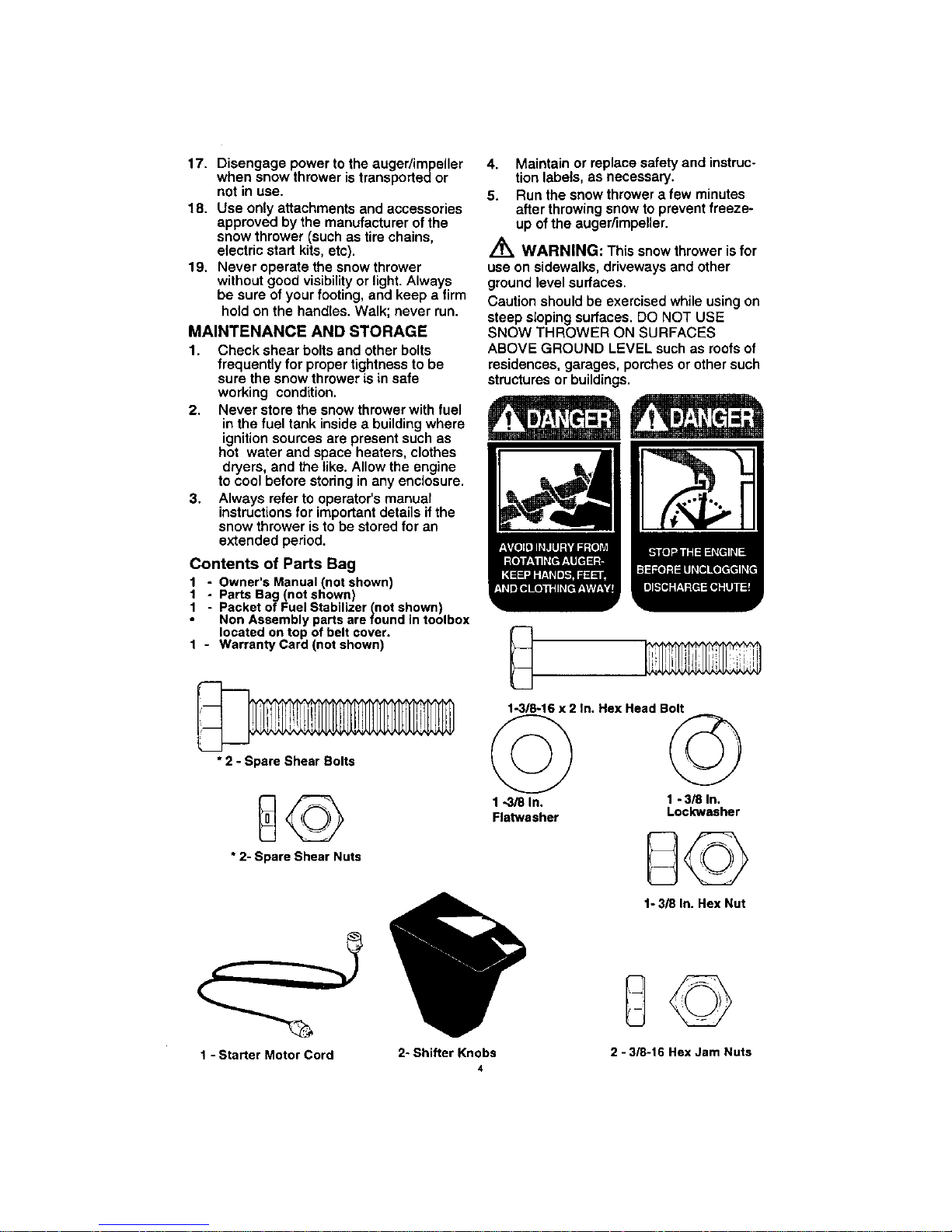
Contents of Parts Bag
1 - Owner's Manual (not shown)
1 - Parts Bag (not shown)
! - Packet of Fuel Stabilizer (not shown)
Non Assembly parts are found in toolbox
located on top of belt cover.
1 - Warranty Card (not shown)
4. Maintain or replace safety and instruc-
tion labels, as necessary.
5. Run the snow thrower a few minutes
after throwing snow to prevent freeze-
up of the auger/impeller.
Z_ WARNING: This snow thrower is for
use on sidewalks, driveways and other
ground level surfaces.
Caution should be exercised while using on
steep sloping surfaces. DO NOT USE
SNOW THROWER ON SURFACES
ABOVE GROUND LEVEL such as roofs of
residences, garages, porches or other such
structures or buildings.
• 2 - Spare Shear Bolts
• 2- Spare Shear Nuts
1-3/8-16 x 2 In. Hex Head Bolt
©
1_/8 In.
Flatwasher
©
1 - 3/8 In.
Lockwasher
1- 3/8 In. Hex Nut
1 - Starter Motor Cord
2- Shifter Knobs
4
@©
2 - 3/8-16 Hex Jam Nuts
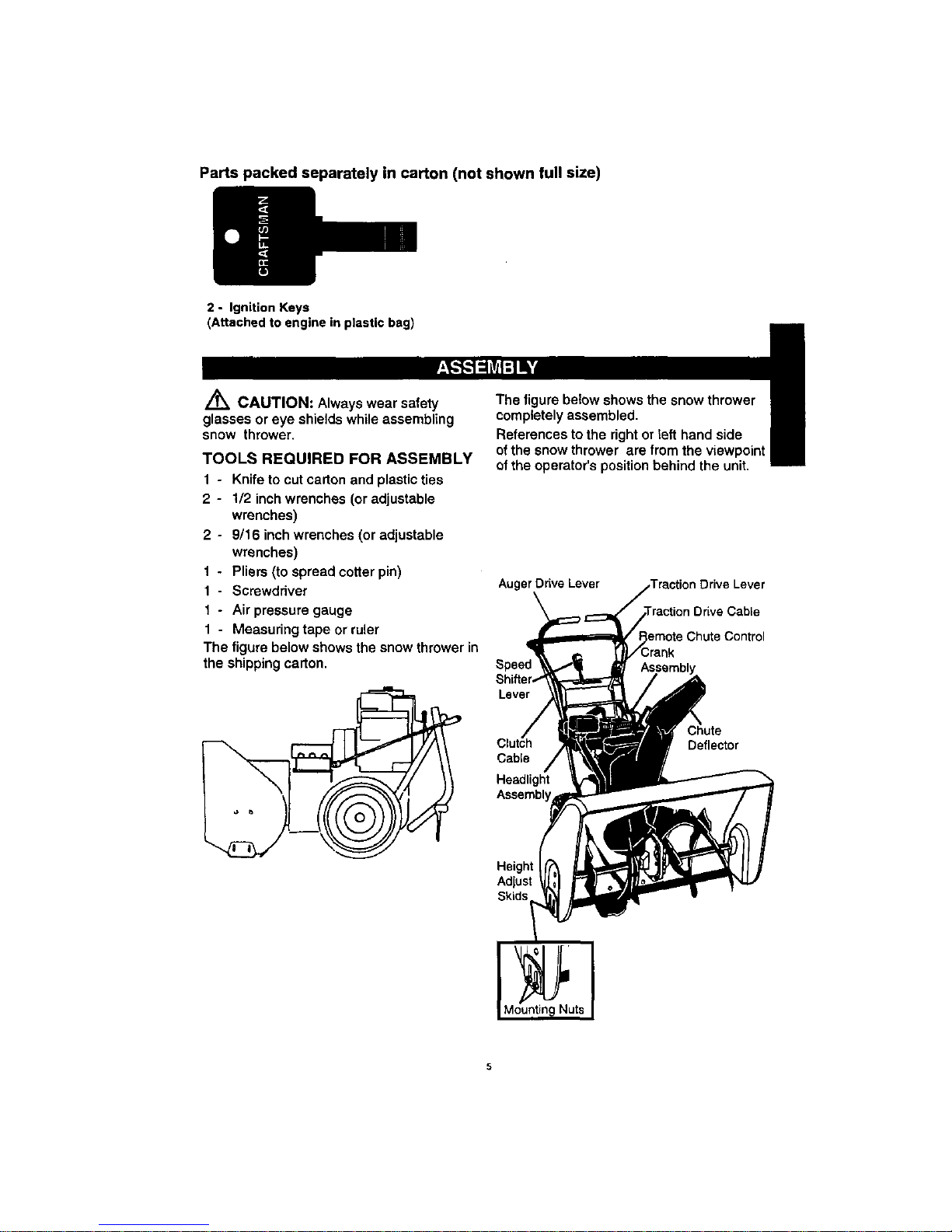
Parts packed separately in carton (not shown full size)
2 - Ignition Keys
(Attached to engine in plastic bag)
Z_ CAUTION: Always wear safety
glasses or eye shields while assembling
snow thrower,
TOOLS REQUIRED FOR ASSEMBLY
1 - Knife to cut carton and plastic ties
2 - 1/2 inch wrenches (or adjustable
wrenches)
2- 9/16 inch wrenches (or adjustable
wrenches)
1 - Pliers (to spread cotter pin)
1- Screwdriver
1 - Air pressure gauge
1 - Measuring tape or ruler
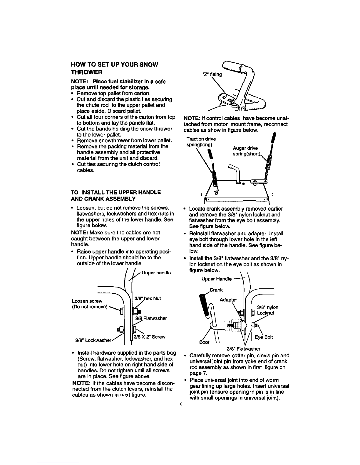
The figure below shows the snow thrower in
the shipping carton.
,i
The figure below shows the snow throwe_
completely assembled.
I
References to the right or teft hand side
ofthe snow thrower are from the viewpoint
of the operator's position behind the unit,
Auger Drive Lever
Speed
Lever
Cable
Headlight
Chute
Deflector
Height
Adjust
HOW TO SET UP YOUR SNOW
THROWER
NOTE: Place fuel stabilizer In a safe
place untll needed for storage.
• Remove top pallet from carton.
• Cut and discard the plastic ties securing
the chute rod to the upper pallet and
place aside. Discard pallet.
• Cut all four comers of the carton from top
to bottom and lay the panels flat.
• Cut the bands holding the snow thrower
to the lower pallet.
• Remove snowthmwer from lower pallet.
• Remove the packing material from the
handle assembly and all protective
material from the unit and discard.
• Cut ties securing the clutch control
cables.
"z"fitting
NOTE: If control cables have become unat-
tached from motor mount frame, reconnect
cables as show in figure below.
Tractiondrive I
spdng(Iong)
i Augerdrive
TO INSTALLTHE UPPER HANDLE
AND CRANKASSEMBLY
• Loosen, but do not remove the screws,
flatwashers, leckwashers and hex nuts in
the upper holes of the lower handle. See
figure below.
NOTE: Make sure the cables are not
caught between the upper and lower
handle.
• Raise upper handle into operating posi-
tion. Upper handle should be to the
outside of the lower handle.
--_t _/" Upper handle
Loosenscrew _'_'hex
Nut
(Do notremove)
I;
_8Flatwasher
t"
Lockwasher//_ 3/8 X 2"Screw
3/8"
• Install hardware supplied in the parts bag
(Screw, flatwasher, Iockwasher, and he:<
nut) into lower hole on right hand ,side of
handles. Do not tighten untilall screws
are in place. See figure above.
NOTE: If the cables have become discon-
nected from the clutch levers, reinstall the
cables as shown in next figure.
Locate crank assembly removed earlier
and remove the 3/8" nylon Iocknut and
flatwasher from the eye bolt assembly.
See figure below.
Reinstall flatwasher and adapter. Install
eye bolt through lower hole in the left
hand side of the handle. See figure be-
low.
install the 3/8" flatwasher and the 3/8" ny-
lon Iocknut on the eye bolt as shown in
figure below.
3/8"nylon
Locknut
Eye Bolt
Boot
3/8" Flatwasher
• Carefully remove cotter pin, clevis pin and
universal joint pin from yoke end of crank
rod assembly as shown in first figure on
page 7.
• Place univemal joint into end of worm
gear lining up large holes. Insert universal
joint pin (ensure opening in pin is in line
with small openings in universal joint).
6
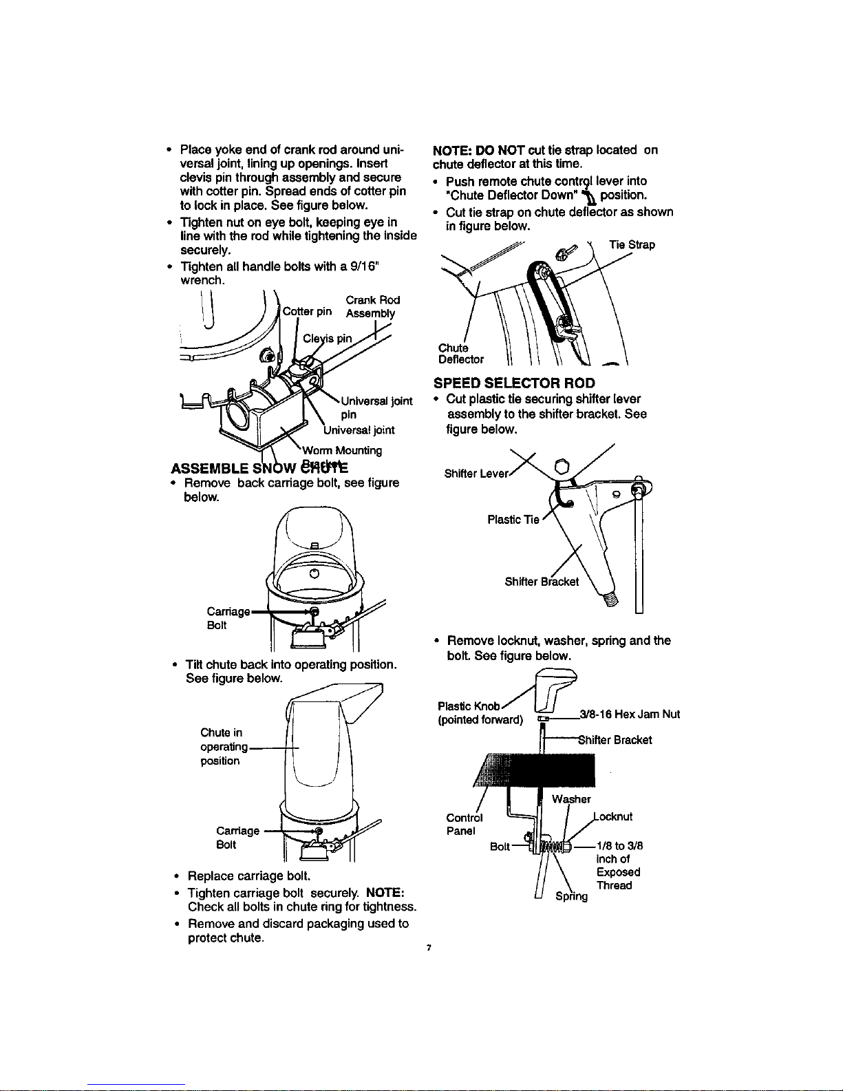
• Place yoke end of crank rod around uni-
versal joint, lining up openings. Insert
clevis pin through assembly and secure
with cotter pin. Spread ends of cotter pin
to lock in place. See figure below.
• Tighten nut on eye bolt, keeping eye in
line with the rod while tightening the inside
securely.
• Tighten all handle bolts with a 9/16"
wrench.
Crank Rod
Assembly
NOTE: DO NOT cut tie strap located on
chute deflector at this time.
• Push remote chute co n.trgllover into
•Chute Deflector Down '_, position.
• Cut tie strap on chute deflector as shown
_nfigure below.
Tie Strap
Joint
pin
joint
ASSEMBLE
• Remove back cardage bolt, see figure
below.
Bo_tCardagem
• Tilt chute back intooperating position.
See figure below.
Chute in
operating
position
Bolt
• Replace carriage bolt.
• Tighten carriage bolt securely. NOTE:
Check all bolts in chute ring for tightness.
• Remove and discard packaging used to
protect chute.
Chute
Deflector
SPEED SELECTOR ROD
• Cut plastic tie securing shifter [ever
assembly to the shifter bracket. See
figure below.
\
• Remove Iocknut, washer, spring and the
bolt. See figure below.
Plasticl_ob_
(pointedforward) _._3/8-16 HexJam Nut
I_-'-Shifter Bracket
Control
Panel
--1/8 tO3/8
inch of
Exposed
Thread
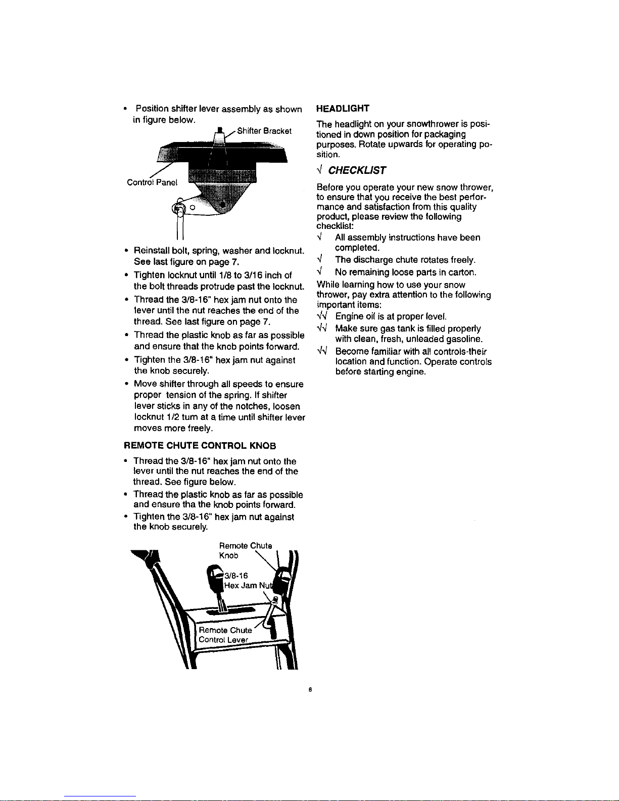
Position shifter lever assembly as shown
in figure below.
,€
Control Panel
• Reinstall bolt, spring, washer and Iocknut.
See last figure on page 7,
• Tighten Iocknut until 1/8 to 3/16 inch of
the bolt threads protrude past the Iocknut
• Thread the 3/8-16" hex jam nut onto the
lever until the nut roaches the end of the
thread. See last figure on page 7.
• Thread the plastic knob as far as possible
and ensure that the knob points forward.
• Tighten the 3/8-16" hex jam nut against
the knob securely.
• Move shifter through all speeds to ensure
proper tension of the spring. If shifter
lever sticks in any of the notches, loosen
Iocknut 1/2 turn at a time until shifter lever
moves more freely.
REMOTE CHUTE CONTROL KNOB
• Thread the 3/8-16" hex jam nut onto the
lever until the nut roaches the end ofthe
thread, See figure below.
• Thread the plastic knob as far as possible
and ensure tha the knob points forward.
• Tighten the 3/8-16" hex jam nut against
the knob securoly.
RemoteChute
Knob
3/8-16
HEADLIGHT
The headlight on your snowthrower is posi-
tioned in down position for packaging
purposes. Rotate upwards for operating po-
sition.
CHECKLIST
Before you operate your new snow thrower,
to ensure that you receive the best peffor-
mance and satisfaction from this quality
product, please review the following
check|ist:
-J All assembly instructions have been
completed.
_/ The discharge chute rotates freely.
q" No remaining loose partsin carton.
While learning how to use your snow
thrower, pay extra attention to the following
important items:
_/_ Engine oil isat proper level.
_/4 Make sure gas tank is filled properly
with clean, fresh, unleaded gasoline.
4_/ Become familiar with all controls-their
location and function. Operate controls
before starting engine.
 Loading...