

Page 1
Caution:
Read and Follow
All Safety Rules
and Instructmns
,,,,,,,,,, ,,, , .........
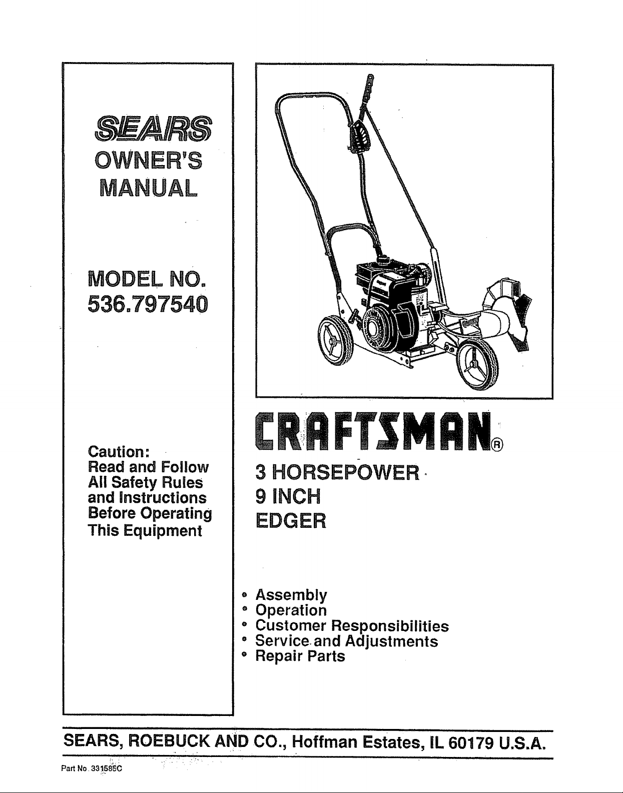
3 HORSEPOWER .
9 iNCH
Before Operating
EDGER
This Equipment
o Assembly
" Operation
o Customer Responsibilities
° Serviceand Adjustments
• Repair Parts
SEARS, ROEBUCK AND CO., Hoffman Estates, iL 60179 U.S.A.
=
PartNo,33_58SC
Page 2
SAFETY RULES
CAUTION: ALWAYS DISCONNECT SPARK PLUG WIRE AND PLACE WIRE WHERE IT A
CANNOT CONTACT SPARK PLUG TO PREVENT ACCIDENTAL STARTING WHEN SET-
TING-UP, TRANSPORTING, ADJUSTING OR MAKING REPAIRS
4t
BEFORE USE
• Read the owner's manual carefully+ Be thoroughly
familiar with the controls and the proper use of the
edger. Know howtostop the edger anddisengage the
controls quickl'y.
@ Do not operatethe edger withoul wearing adequate
outer garments. Wear footwear thatwillimprove foot-
ing on sUpperysurfaces.
@ Keep the area of operation clear of all persons,
particularly small children_lndpets+:
@ Thoroughly inspect the area wheretheedger istobe
used and remove all foreign objects,
FUEL SAFETY
• Handte fuel with care; it is highly flammable°
• Use an approved container.
• Checkfuelsupplybeforeeachuse, allowingspacefor
expansion as the heat of the engine and/or sun can
cause fuel to expand..
• FiUfuettankoutdoorswith extreme care=Neverfilliuel
tank indoors+Replace |uel tankcap securely and wipe
up spilled fuel+
• Never remove the fuel tank cap or add fuel to a
runningor hot engine,.
• Neverstorefuel oredgerwith fuelinthetank inside a
buitdingwhere fumes may reach an openflame+
OPERATING SAFETY
@ Never allow childrenor youngteenagers to operate
the edger+ Keep them away while it is operating.
Never allow aduttsto operate the edgedtdmmer with+
out proper instruction+
Ill Nways wear safety glasses or eye shields during
operationor while performing an adjustment orrepair
toprotect your eyes from foreign objects that may be
thrownfrom the edger+
@
Donot put hands orfeet near or under rotating parts+
@
Exercise extreme caution when operating onorcross-
{nggravel drives, walks, or roads.Stayalert forhidden
hazards or traflic.
@ Exercise caution to avoid slipping or falling.
@ Neveroperate the edgerwithout properguards,plates,
or other safety protective devices in place.
@ Never operate the edger at high transportspeeds or+
slipperysurfaces. Look behind and use care when
backing.
@ Never allow bystanders near the edger.
@ Keep childrenand petsaway whileoperating+
• Neveroperatetheedgerwithoutgood v!sibilityorlight.
• Donot runtheengineindoors.Theexhaustfumes are
dangerous (containingCARBON MONOXIDE, an
ODORLESS and DEADLY GAS).
@ Take a!l possibteprecautionswhenleavingthe edger
unattended+ Stopthe engine+
@ Do not overload the edger capacityby attemptingto
edge toodeet_at too fast a rate.
SAFE STORAGE
@
Always reter to the owner'smanual storage section
for importantdetails if the edgeris to be stored for an
extended period+
@
Neverleave the edger with fuel in the fuel tank inside
abuilding where ignition sources are present such as
water andspaceheaters, clothesdryers, and thelike.
Allow the engine to cool before placing in any enclo-
sure.
@ Keep the edger in safe working condition. Check all
fasteners at frequent intervalsfor proper tightness
REPAiR!ADJUSTMENTS SAFETY'
@ Afterstdking aforeign object, stopthe engine (motor).
Remove the wire from the spark plug, and keep the
wire away fro mthe plug to prevent accidental starting..
Thoroughly inspectthe edger for any damage, and
repair the damage before restarting andoperating the
edger.
@ litheedger shouldstartto vibrate abnormally, stopthe
engine (motor) andcheck immediately {orthe cause
Vibration is generaUy a warning of troubte.
@ Stop the blade whenever you leave the operating
position. Also, stop the engine and disconnect the
spark plug wire before unclogging theblade andwhen
making any repairs, adjustments, or inspections
@ When cteaning, repairing,or inspecting, shuto{{ the
engine andmakecertain allmovingpartshave stopped
@ Never attempt to make any adjustments while the
engine is running (except when specitically recom-
mended by themanufacturer).
+
! oo, o+0L+0++0u++o.+++
ATTENTIONIt! BECOME ALERTLI! YOUR SAFETY IS INVOLVED, 1
Page 3
CONGRATULATIONS on your purchase of a Sears
Craftsman Edger. tt has been designed, engineered and
manufactured togive youthe best possible dependability
and per/ormanceo
Should you experience any problem you cannot easily
remedy, please contact your nearest Sears Service
Center/Deparlment. We have competent, well-trained
technicians and the proper tools to service or repair this
unit,.
Please read and retain this manual.. The inslruc!ions will
enable you to assemble and maintain your edgei: prop-
erlyo Always observe the "SAFETY RULES."
MODEL
NUMBER 536,797540
SERIAL
NUMBER
DATE OF
PURCHASE
THE MODEL AND SERIAL NUMBERS WILL BE
FOUND ON A DECAL ON THE FRAME OF THE
EDGER BEHIND THE ENGINE.
YOU SHOULD RECORD BOTH SERIAL NUMBER
AND DATE OF PURCHASE AND KEEP IN ASAFE
PLACE FOR FUTURE REFERENCE..
MAINTENANCE AGREEMENT
A Sears Maintenance Agreement is available on this
product. Contact your nearest Sears Store for details.
PRODUCT sPEC!FICATIONS
" " i i i i lll l i
_HORSE POWER; 3.0 hp
DISPLACEMENT: 9.06 cu. in.
(148 c.c)
GASOLINE CAPACITY: 1,0 qt.
Unleaded
(Regular)
20 oz.
SAE- 3OW
SPARK PLUG : Champion
(GAP .030 in.) CJ-8 or
Equivalent
CUSTOMER RESPONSIBILITIES
e Read and observe the Safety rules.
@ Follow a regular schedule in maintaining, caring for
and using your edger.
@ Follow the instructions under "Customer
Responsibilites"and"Storage" sections of thisowner's
manual
ONE YEAR LIMITED WARRANTY ON CRAFTSMAN
EDGER
For one year from the date of purchase,when this Craftsman Edger is maintained, lubricated and tuned-
up according to the instructions in the owner's manual, Sears will rePair, free of cl_arge, any detect in
material and workmanship
I! this Craftsman Edger is used for commercial or rental purposes, this warranty applies for only 90 days
{rbmthe date of purchase.
This warranty does not cover the following:
e Expendable items which become worn during normat use, such as spark plugs, etc
• Repairs necessary because of operator abuse or negligence, including bent crankshafts and the failure
to maintain the equipment according to the instructionscontained in the owner's manual
WARRANTY SERVICE ISAVAILABLE BY RETURNING THE CRAFTSMAN EDGER TO THE NEAREST
SEARS SERVICE CENTERIDEPARTMENT IN THE UNITED STATES THIS WARRANTY APPLIES
ONLY WHILE THiS PRODUCT tS IN USE IN THE UNITED STATES
This warranty gives you specific legal rights, and you may also have other righls which may vary trom
state to state
SEARS, ROEBUCK AND CO. Depadment D/871WA, Hoffmar] Estates, {L 60179
WARNING: This unit is equipped with aninternal combustion engine and should not beused on or near anyunimproved
foresFcovered, brush-covered or grass-covered land unless the engine's exhaust system is equipped with a spark
arrester meeting applicable local or state taws (if any) If a spark arrester is used, it should be maintained in effective
working order by the operator
In the state of California the above is required by law (Section 4442 of the California Public Resources Code) Other
states may have similar laws. Federal laws apply on federal lands A spark attester/muffler [savailable lhrough your
nearest Sears Authorized Service Center (See REPAIR PARTS section in this manuaI)
3
Page 4
TABLE OF CONTEN rs
SAFETY RULES ,_......................................... 2
PRODUCT SPECIFICATIONS ...................... 3
CUSTOMER RESPONSIBILITIES ..... 3,12,13
WARRANTY .................................................. 2
TABLE OF CONTENTS .............. ................... 4
CONTENTS OF HARDWARE PACK ............ 5
ASSEMBLY ................................................ 6-7
INDEX
A
Adjustments:
Carburetor................................ 15
Assembly ..........................................6-7
Tools Required ............................ 6
To Assemble ........................... 6-7
B
Belt:
Removal/Replacement ................14
Blade:
Replacement ..........................14,15
CarburetorAdjustment...................15
Check List:
Operation ...........................................7
Maintenance ............................ 12
Clutch ......................._......................8,9
Controls,Edger ..............................8,9
Customer Respons_ilities.°.3,12,13
General Recommendations ....12
Lubrication.......................... 12,13
Edger ...............................................12
Er_jlne ...............................12,13
/kit Cleaner, Engine...................13
Spark Plugs ....................................13
Engine:
Air Cleaner .................................13
Oil Change ....:........................... 12
Oil Level ...................................9,12
Oil Type ................................3,9,12
Preparation ..................................9
Starting................................................11
Storage...........................................16
Edger Tips .......................................11
Fuel:
Type ........................................................9
Storage ..........................................16
General Recommendations .........12
Lubrication:
Edger ......................................12
Engine .......................................12,13
Oil:
Cold Weather Conditions ......9,12
Engine ..............................................9,12
Storage............................................16
Type ......................................3,9,12
Operation ..........................................8-11
Operating Your Edger ......................9
OPERATION..., ........................................ 8-11
SERVICE AND ADJUSTMENTS .., ........ 14-15
STORAGE .............................................. ,....16
TROUBLE SHOOTING ............................... 17
REPAIR PARTS (EDGER)..; ................ 18-24
REPAIR PARTS (ENGINE) ................... 25-28
PARTS ORDERING/SERVICE .....Back Cover
E
PartsBag..............................................5
PrimerButton.......,........................8,9
ProductSpech'ications.................. 3
Repair Pads:
Edger ................................................18-24
Engine ..................................25-28
F
Safety Rules ....................................2
Service and Adjustments ..........t4-15
Carburetor.................................15
V-Belt:
G
L
O
Removal/Replacemer_t ....................14
Specifications......................................3
Starting the Engine ...........................11
Stoppingthe Edger ..._..............................9
Storage.............................................16
Table of Contents .............................4
ThrottleControl...............................9
TroubleshootingPo{nts ..................... 1 7
Warranty...............................................2
P
R
S
T
W
Page 5
CONTENTS OF
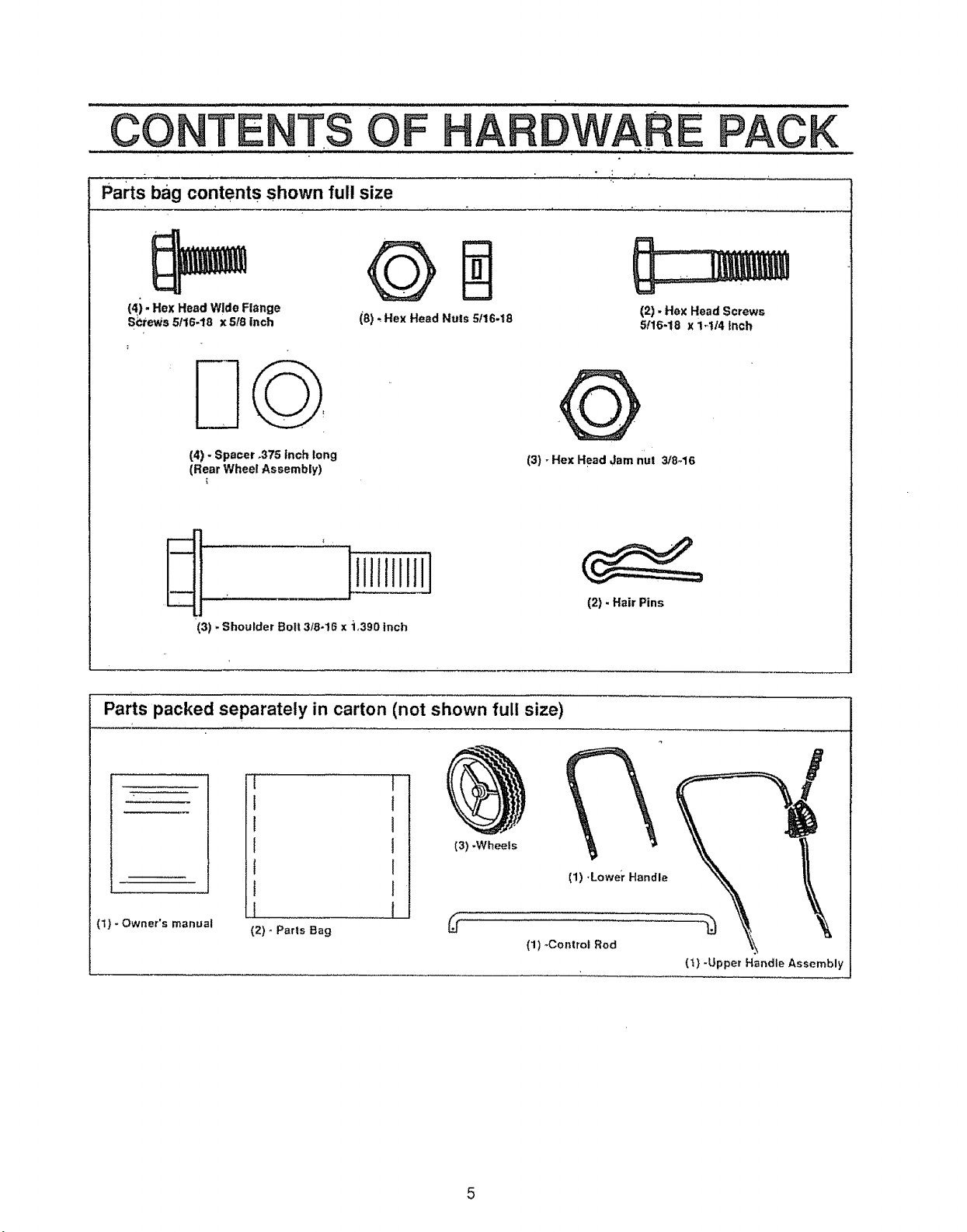
Parts bag contents shown full size
ARDW'ARE
PACK
(4i" Hex Head Wide Range
S_tews 5/16-18 x 518 inch
(4) -Spacer .375 inch Gong
(Rear Wheel Assembly)
(3) -Shoulder Bolt 3/8-!6 x 1,390 inch
Parts packed separately in carton (not shown full size)
(8) * Hex Head Nuts 5t16-18
(3) - Hex Head Jam n'ut 3/8-16
1
(2) - Hex Head Screws
5116-18 x 1,1/4 inch
(2) - Hair PEns
.....t,
l
1
f
f
J
(1} - Owner's manual ._
(2)- Parts Bag
(3) -Wheels
(1) -Lowe;r Handle
(1) -Control Rod
(t) -Upper Handle Assembly
Page 6
EMBLY
TOOLS REQUIRED FOR ASSEMBLY TO ASSEMBLE THE EDGER
1 - 314inch Wrench (or adjustable wrench)
2 - 1/2 inch Wrenches (or adjustable wrenches)
1 - Pair Pliers Ill
1 - Regular Screwdriver
2- 9/!6 inch Wrench ( or adjustable wrenches)
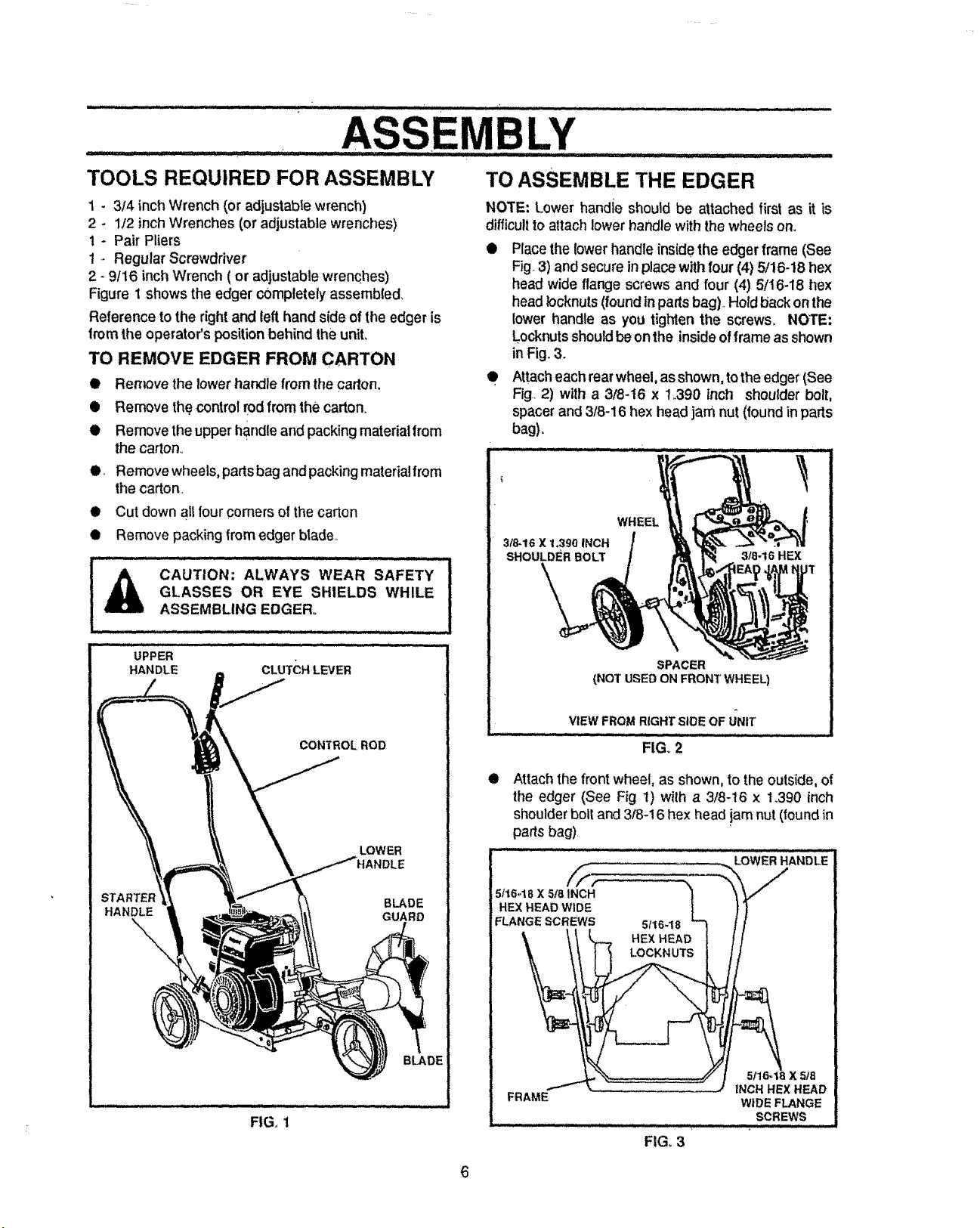
Figure 1 shows the edger completely assemb(ed_
Reference to the rightand left hand side of the edger is
from the operator's position behind the unit.
TO REMOVE EDGER FROM CARTON
tt
Remove the lower handle from the carton.
e
Remove the control rodfrom the carton.
e
Remove theupper handleandpackingmaterialfrom
the carton_
e.. Remove wheels,partsbagand packingmaterialfrom
the carton.
• Cut downall four comersof the carton
• Remove packingfrom edgerblade_
....,_ CAUTION: ALWAYS WEAR 'SAFETY !
GLASSES OR EYE SHIELDS WHILE |
ASSEMBLING EDGER.
NOTE: Lower handle should be attached first as it is
difficult to attach lower handle with the wheels on.
Place the lower handle inside the edgerlrame (See
Fig.3) and secure inplace withfour (4) 5/16-18 hex
head wide flange screws and four (4) 5;/16-18 hex
head Iocknuts (found inparts bag), Hold back on the
lower handle as you tighten the screws,. NOTE:
Locknuts should be on the inside of frame as shown
in Fig. 3.
• Attach each rear wheel,as shown, to the edger (See
Fig 2) with a 3/8-t6 x i_390 inch shoulder bolt,
spacer and 3/8-16 hex head jam nut (found in parts
bag).
........... ............ _ L ....
WHEEL
3/8-16 X 1,390 INCH
SHOULDER BOLT 318-16 HEX
1
FIG. 1
SPACER
(NOT USED ON FRONT WHEEL)
VIEW FROM RIGHT SIDE OF UNIT
FIG. 2
ill Attach the front wheel, as shown, to theoutside, of
the edger (See Fig 1) with a 3/8-t6 x 1.390 inch
shoulder boll and 3/8-16 hex head jam nut (found in
parts bag)
_: ii ,i i, LowER HANDLE ....
HEX.EADW_OE | t/
FLANGE SCREWS 5t16-18 _'3 { /
\ \\ % HE .E O1 //
I_" 7"7: .. -': ..j INCH HEXHEAD
FRAME WIDE FLANGE
....................1# °,,°,,ox,,=
...... : , ,iuLJ
FIG, 3
SCREWS
6
Page 7
ASS L¥
" • ' _ u,1,,i,iii, t ....'
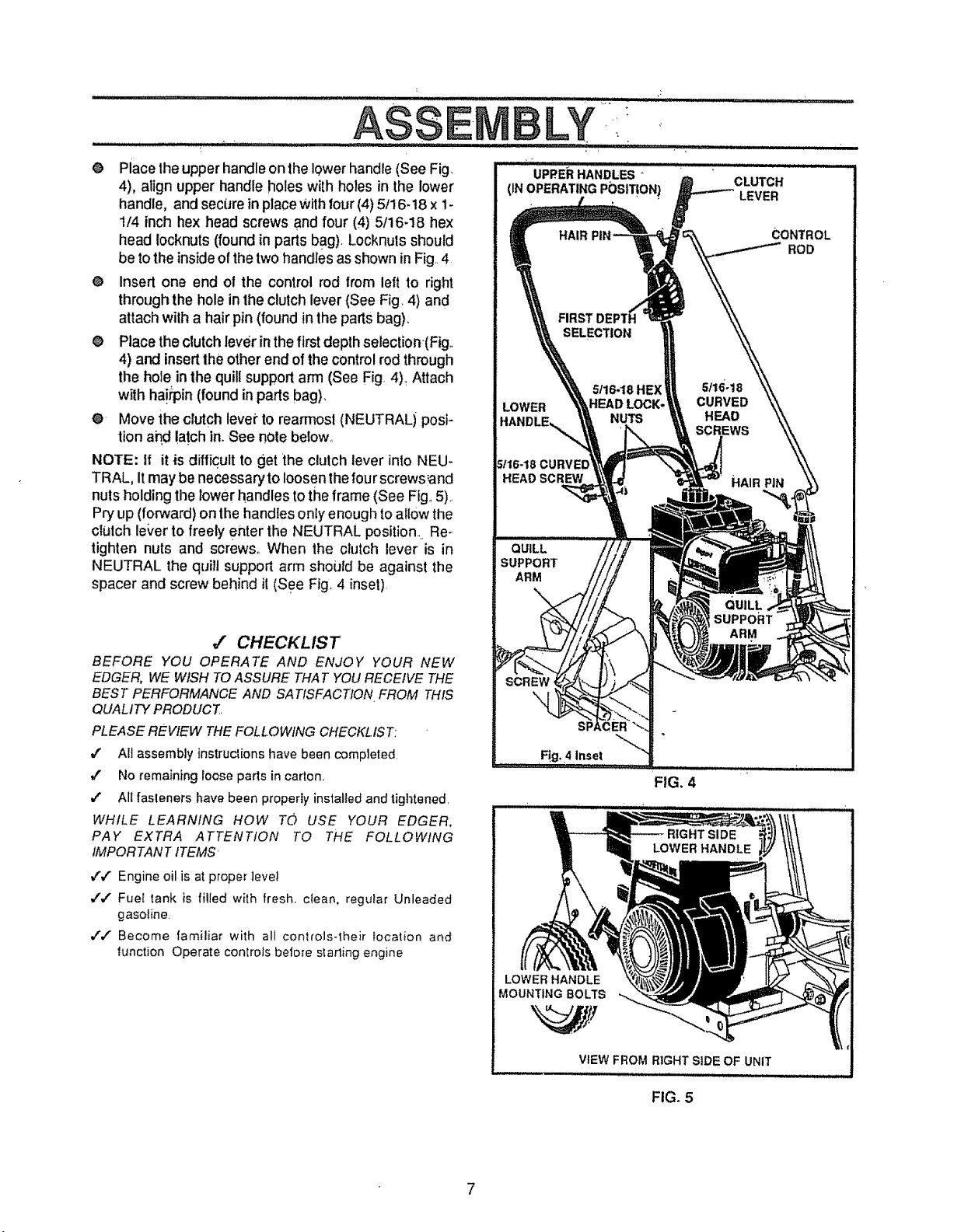
• Place theupper handle on the lower handle (See Fig.
4), aiign upper handle holes with holes in the lower
handle, and secLJreinplace Withfour (4) 5/16-18 x 1-
1/4 inch hex head screws and four (4) 5/16-18 hex
head locknuts (found in parts bag). Locknuts should
be to the insideof the two handles asshown in Fig..4
O Insert one end ol the control rod from left to right
through the hole in the clutch lever (See Fig, 4) and
attach with a hair pin (found in the parts bag),
O Place the clutch lever inthe first depth selection-(Figo
4) and insert the other end of the control rod through
the hole in the quill support arm (See Fig. 4)_Attach
with ha!qoin(found in parts bag),
@ Move the clutch levei"to rearmost (NEUTRALi posi-
tion ahd !a!ch in. See note below_
NOTE: tf it is difficult to get the clutch lever into NEU-
TRAL, It may be necessary to loosen the four screws'and
nuts holding the lowerhandles to the frame (See Fig•.5).
Pry up (forward) on the handles onty enough to allow the
clutch le_,erto freely enter the NEUTRAL position.. Re-
tighten nuts and screws° When the clutch lever is in
NEUTRAL the quitl support arm shoiJid be against the
spacer and screw behind it (See Fig. 4 inset),
J CHECKLIST
BEFORE YOU OPERATE AND ENJOY YOUR NEW
EDGER,WE WISHTOASSURE THATYOURECEIVETHE
BEST PERFORMANCEAND SATISFACTION.FROM THIS
QUALITYPRODUCT
PLEASEREVIEWTHEFOLLOWINGCHECKLIST:
4' Aft assemblyinstrucl[onshave beencompleted.
J Noremainingioosepartsin carton..
,/ All {asleners have been properly installed and tightened,
WHILE LEARNING HOW TO USE YOUR EDGER,
PAY EXTRA ATTENTION TO THE FOLLOWING
1MPORTANTtTEMS'
JJ' Engine oil is at proper level
,/'v" Fuel tank is filled with fresh• ctean, regutar Unleaded
gasoline.
,/,f Become familiar wilh all controls-their Iocafion and
function Operate conlrolsbefores_,arling engine
UPPER HANDLES °
(IN OPERATING POSIT!ON!
HAIR CONTROL
SELECTION
LOWER HEAD LOCK. CURVED
HANDLE_ NUTS HEAD
ED
HEAD SCREW
QUILL
SUPPORT
ARM
F!g. 4 Inset
LOWER HANDLE
MOUNTING BOLTS
ii,,, ,, ,,,
CLUTCH
LEVER
ROD
5f16-18 HE]< 5116-18
SCREWS
HAIR PiN
QUILL
SUPPORT
ARM
FIG. 4
FIGo 5
Page 8
OPERATION
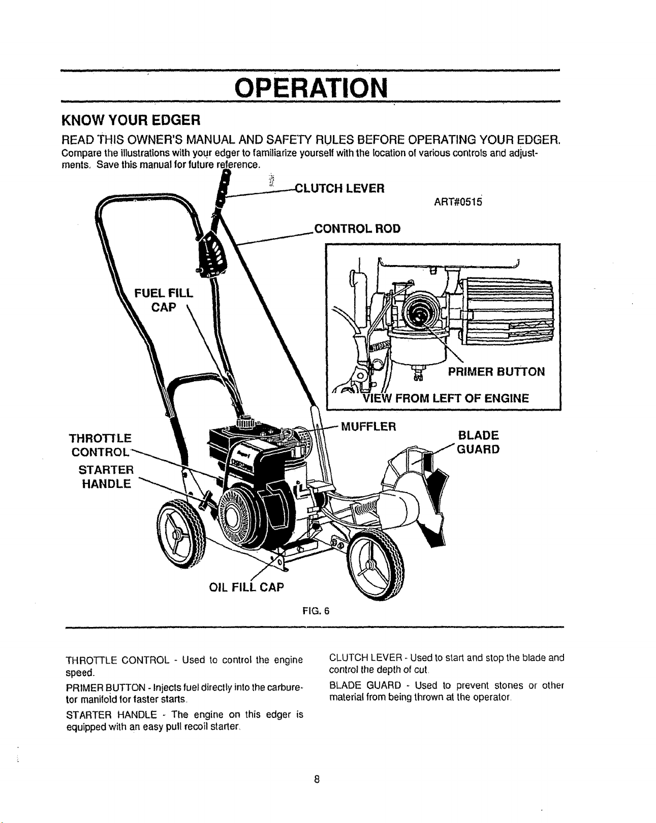
KNOW YOUR EDGER
READ THIS OWNER'S MANUAL AND SAFETY RULES BEFORE OPERATING YOUR EDGER.
Compare the illustrationswith you? edger to familiarize yourselfwith the location of various controls and adiust-
merits, Save this manual forfuture
LEVER
ART#0515
CONTROL ROD
FUEL FILL
CAP \,_
PRIMER BUTTON
THROTTLE
CONTROL
STARTER
HANDLE
OIL FILL CAP
THROTTLE CONTROL - Used to control the engine
speed.
PRIMER BUTTON - Injects fuel directly into the carbure o
tot manifoid for faster starts,
STARTER HANDLE - The engine on this edger is
equippedwith an easy pull recoil starter_
VIEW FROM LEFT OF ENGINE
BLADE
ARD
FIG. 6
CLUTCH LEVER - Used to start and stop the blade and
control the depth of cut
BLADE GUARD - Used to prevent stones or other
material from being thrown at the operator
Page 9
............................................ERA'rUo............•.....
The operationof this edgercan resultinforeign objectsbeing'thmwn int0the eyes,
which can result in severe eye damage. Always Wearsafety glasses oreye shields
whileoperatingthe edger.
We recommend Standard safety glasses or Wide Vision Safety Mask for over your
: :: ::! !: i ii,ul,,ll,u,ull, i i i,,i _ .......... ,
HOW TO USE YOUR EDGER
glasses,,
TO STOP EDGER
O
To stop the engine, make sure the clutchlever is all
the way back (or up) and move the throttlecontrol
lever to the STOP position
. ,i IIIIIIlU'IHIIn"Ii,ilnl _ -
CAUTION: NEVER LEAVE THE EDGER IUNATTENDED WHILE THE ENGINE IS i
RUNNING. ALWAYS DISENGAGE THE ! J
CUTTING BLADE AND STOP THE I
ENGINE. , " I
TO USE THROTTLE CONTROL
O Run at fullengine speed during normal user
O. Push throttle control lever up to increase speed;
down to decrease speed,
TO USE PRIMER BUTTON
e Push pdmer button five (5) times (see Fig. 6)o Wait
about two (2) seconds between each push.
NOTE: Do not use primer to restart a warm engine after
a short shutdown,
TO USE THE CLUTCH LEVER
e Start the engine and move the clutch lever forward
(or down) to engage the cutting blade.
e Select the edging depth you need There are 5
selections up to 2-3/4 inches deep,,
IMPORTANT: IFVERY DEEP EDGING ISREQUIRED,
WE RECOMM EN DTHAT A SHALLOW
C[,ITBE MADE FIRST, THEN CUTS AT
GREATER DEPTHS UNTIL THE
DESIRED DEPTH IS OBTAINED
TATING BLADE. THE BLADE CAN
CAUTION; KEEP AWAY FROM THE RO- I
CAUSEiNJURY. " I
:7 _ ]_III11]111 H ,llrllll , "r' I 11111]11111_I,t I
BEFORE STARTING ENGINE
PRE-USE CHECK OF CONTROLS
Al!controls should becheckedfor proper func!ionbefore
servicingor starting the engine.
O Move the clutch leverintoall six (6) positionsirl the
selectorplate° Make sure theclutch lever snaps into
all six(6) holes, (Fig. 6)
O Return the clutch lever to the rearmost hole in the
selectorplate
FILL/ADD OIL:
The engine on thisedger was shipped with littleor nooi!,
Add oilbefore you start the engine,
OIL RECOMMENDATIONS
Only use highquality detergent oi1rated withAPI service
classification SG Select the"oil's SAE viscositygrade
according to your expected operating temperature:
32OF ' ]
COLDER<< ! - _>WARMER
5W30 SAE30
NOTE: Although•multi-Viscosity oits(5W30, 10W30, etc.)
improvestarting incoldweather,thesemultFviscosity oils
willresuti inincreasedoilconsumptionwhenused above
32°F Check yourengineoillevel morefrequently toavoid
possible engine damage from running low on oil
TO ADD ENGINE OIL
@ Place the edger on a level surface
@
Remove the oil fitl cap (Fig 7A)
e
Fill the engine crankcase, pouring slowly Do not
overfill. For approximate capacity see PRODUCT
SPECIFICATIONS on page 3 of this manual
®
Reinstall the oil fi!l cap and tighten securely.
®
Check oil before each use. Add if needed
®
Change oil afterthe first2 operating hours and every
25 operating hours thereafter.
_J
t
Page 10
WHILE THE ENGINE IS RUNNING OR
CAUTION: NEVER FILL THE GAS TANK
HOT, IMMEDIATELY WIPE OFF ANY
SPILLED GASOLINE BEFORE AT-
TEMPTING TO START THE ENGINE,
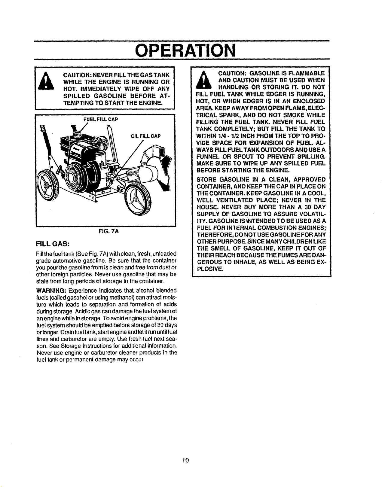
FIGo7A
FILL GAS:
Fillthefueltank(See Fig. 7A) withclean, fresh,unleaded
grade automotive gasoline_ Be sure that the container
you pour the gasoline from isclean and free from dust or
otherforeign particles.. Never use gasoline that may be
stale fromlong periods of storage in the container.
WARNING: Experience indicates that alcohol blended
fuels (called gasoho! or using methanol) can attract mois-
ture which leads to separation and formation of acids
dudng storage. Acidic gas can damage thefue!system of
anengine while in storage. Toavoid engine problems, the
fuel system should be emptied before storage of 30 days
or lor_jer_Drain fuel tank, start engine andletitrununtil fuel
lines and carburetor are empty_ Use fresh fuel next sea-
son. See Storage Instructions for additional information_
Never use engine or carburetor cleaner products in the
fuel tankor permanent damage may occur
AND CAUTION MUST BE USED WHEN
CAUTION: GASOLINE IS FLAMMABLE
HANDLING OR STORING IT. DO NOT
FILL FUEL TANK WHILE EDGER IS RUNNING,
HOT, OR WHEN EDGER IS IN AN ENCLOSED
AREA. KEEP AWAY FROM OPEN FLAME, ELEC-
TRICAL SPARK, AND DO NOT SMOKE WHILE
FILLING THE FUEL TANK. NEVER FILL FUEL
TANK COMPLETELY; BUT FILL THE TANK TO
WITHIN 1/4 - 1/2 INCH FROM THE TOP TO PRO-
VIDE SPACE FOR EXPANSION OF FUEL. AL-
WAYS FILL FUEL TANK OUTDOORS AND USE A
FUNNEL OR SPOUT TO PREVENT SPILLING.
MAKE SURE 1'O WIPE UP ANY SPILLED FUEL
BEFORE STARTING THE ENGINE.
STORE GASOLINE IN A CLEAN, APPROVED
CONTAINER,. AND KEEP THE CAP IN PLACE ON
THE CONTAINER. KEEP GASOLINE IN A COOL,
WELL VENTILATED PLACE; NEVER IN THE
HOUSE, NEVER BUY MORE THAN A 30 DAY
SUPPLY OF GASOLINE "tO ASSURE VOLATIL-
ITY. GASOLINE IS INTENDED TO BE USED AS A
FUEL FOR INTERNAL COMBUSTION ENGINES;
THEREFORE, DO NOT USE GASOLINE FOR ANY
OTHER PURPOSE. SINCE MANY CHILDREN LIKE
THE SMELL OF GASOLINE, KEEP IT OUT OF
THEIR REACH BECAUSE THE FUMES ARE DAN-
GEROUS TO INHALE, AS WELL AS BEING EX-
PLOSIVE.
Jj...,.ll_ Ii i. _....,_
10
Page 11
TO START THE ENGINE
Before starting the engine, be sure you have read and
understoodall the instructionson the precedingpages.
The edgerisequippedwithe recoilsta_er.The operation
ofthe engine ts controlledby tile throttlecontroliever.
O Pul!the clutch lever allthe way back (or up) to the
rearmosthole to raise and disengage the btade,,
o
Movethethrottlecontrollever(See Fig,6) totheRUN
position.
O
Pushprimer button five (5) times (see Fig. 6)_ Wait
about two (2) seconds between each push_
NOTE: Do not use primer to restart a warm engine alter
a short shutdown.
0 To start engine, grasp the engine starter handle
firmlyWithyour righthand
O Holdthe edger handle firmly with your lefthand:
O Pullup sharplyon the recoil starterhandle..DO NOT
allowthe starterrope tosnapback,letitrewind slowly
while holding the starter handle.
NOTE: tf enginefails to start after three (3) pulls,push
primerbutton two (2) times and pullstarter rope again.
O Whenthe enginestarts..Pushthrottlecontrolleverup
to increasespeed; down todecrease speed..Runat
full engine speed during normaluse
NOTE: The cutting blade speed is controlled by the
engine speed. To reduce the cuttingblade speed, push
downon the throttlecontrollever_To increasethe blade
speed, pushthe throttlecontrol lever up.
O To stopthe engine, make sure the clutchlever is all
the way back (or up) and move the throttle control
leverto the STOP position..
CAUTION: NEVER RUN THE ENGINE IN-
DOORS OR IN A POORLY VENTILATED
AREA. ENGINE EXHAUST CONTAINS
CARBON MONOXIDE_ AN ODORLESS
GAS AND DEADLY GAS.
KEEP HANDS, FEET, HAIR AND LOOSE
CLOTHING AWAY FROM ANY MOVING
PARTS ON THE ENGINE OR EDGER,
WARNING - AVOID THE MUFFLER AND
SURROUNDING AREAS (SEE FIG. 6).
TEMPERATURES, MAY EXCEED 150oF.
EDGING TIPS
O
Edging is best performed when conditions are dry. If
the soil is to wet,did becbmes packed inand around
the blade causing premature belt wear and de-
creased performance
0 If dirt does become packed around the blade, stop
the engine, remove the spark plug wire, and remove
the packed debris before continuing to edge.
0 If very deep edging is required, we recommendthat
a shallow cutbemade first,then cuts atgreater depth
until the desired depth is obtained_
0 Uniform edging can be performed when the blade
guide rides on and against the surface which you are
edging
@ Edging can be Customized by varying the numberof
passes and by the distance your blade is from the
surface you are edging
1t
Page 12
CUSTOMER RESPONSIBILITIES
MAINTENANCE
CHECK LIST
BEFORE STORAGE
BEGINNING EACH SEASON
....EVERY 25 HOURS OFUSE
EVERY 10 HOURS OF USE
EVERY 5 HOURS OF USE
FREQUENTLY
BEFORE EACH USE
AFTER FIRST 2 HOURS OF USE
SERVICE RECORD
FILLIN DATES
ASYOU COMPLETE
REGULARSERVICE
LubricateallP_votPoints
LubricateWheelAxles
CheckEngine OilLevel
ChangeEngineOi!
ReplaceAir CleanerFitter
Check Drive Belt
Tighten All Screws and Nuts
Check Blade Wear/Damage
P_
..... e
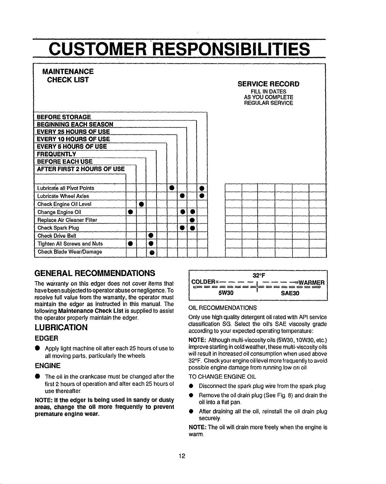
GENERAL RECOMMENDATIONS
The warranty on this edger' does not cover items that
havebeen subjected tooperatorabuse ornegligence. To
receive full value from the warranty, the operator must
maintain the edger as instructed in this manual.. The
followingMaintenance Check List is supplied to assist
the operator properly maintain the edger.
LUBRICATION
EDGER
• Apply light machine oil after each 25 hours of use to
all moving parts, particularly thewheels.
ENGINE
The oil in the crankcase must be changed after the
first2 hours of operation and alter each 25 hours of
use thereafter.
NOTE: If the edger is being used In sandy or dusty
areas, change the oll more frequently to prevent
premature engine wear.
e
e
e
e
e
e
COLDER<_ ,,I *>WARMERs>
OIL RECOMMENDATIONS
Only use highquality detergentoil rated with APt service
classification SG Select the oil's SAE viscosity grade
according to your expected operating temperature:
NOTE: Although multiwiscosity oils (5W30, 10W30, etc.)
improve starting in cold weather, thesemulti-viscosity oils
will result inincreasedoil consumption when used above
32°F. Check your engine oil levelmore frequently to avoid
possible engine damage from runninglow on oil
TO CHANGE ENGINE OIL
• Disconnect the spark plug wire from the spark plug
! Remove the oil drain plug (See Fig 8) and drain the
oil into a fiatpan..
i After draining all the oil, reinstall the oil drain plug
securely.
NOTE: The oilwilt drain more freely when the engine is
warm
f
32OF
5W30 SAE30
12
Page 13
- CUSTO ...................."....................................ESPONSm.. 'lLmTl
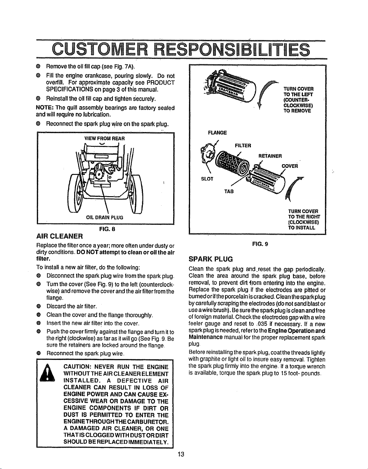
O Remove the oilfillcap (see Fig,,7A),
e Fill the engine crankcase, pouring slowly. Do not
overfill. Foi" approximate capacily see PRODUCT
SPECIFICATIONS on page 3 of this manual,
e Reinstall the 0il fill cap and tighten securely,
NOTE: The quillassembly bearings are factory sealed
and willrequire no lubrication.
e Reconnect the spark plug wire on the spark plug.
i=,l '_1= r_l _Vl,Ii r I ,=,,=l,,ul_ H"
F.o=
V
OILDRAINPLUG
,,,_,_,r::_:::: FIG, 8
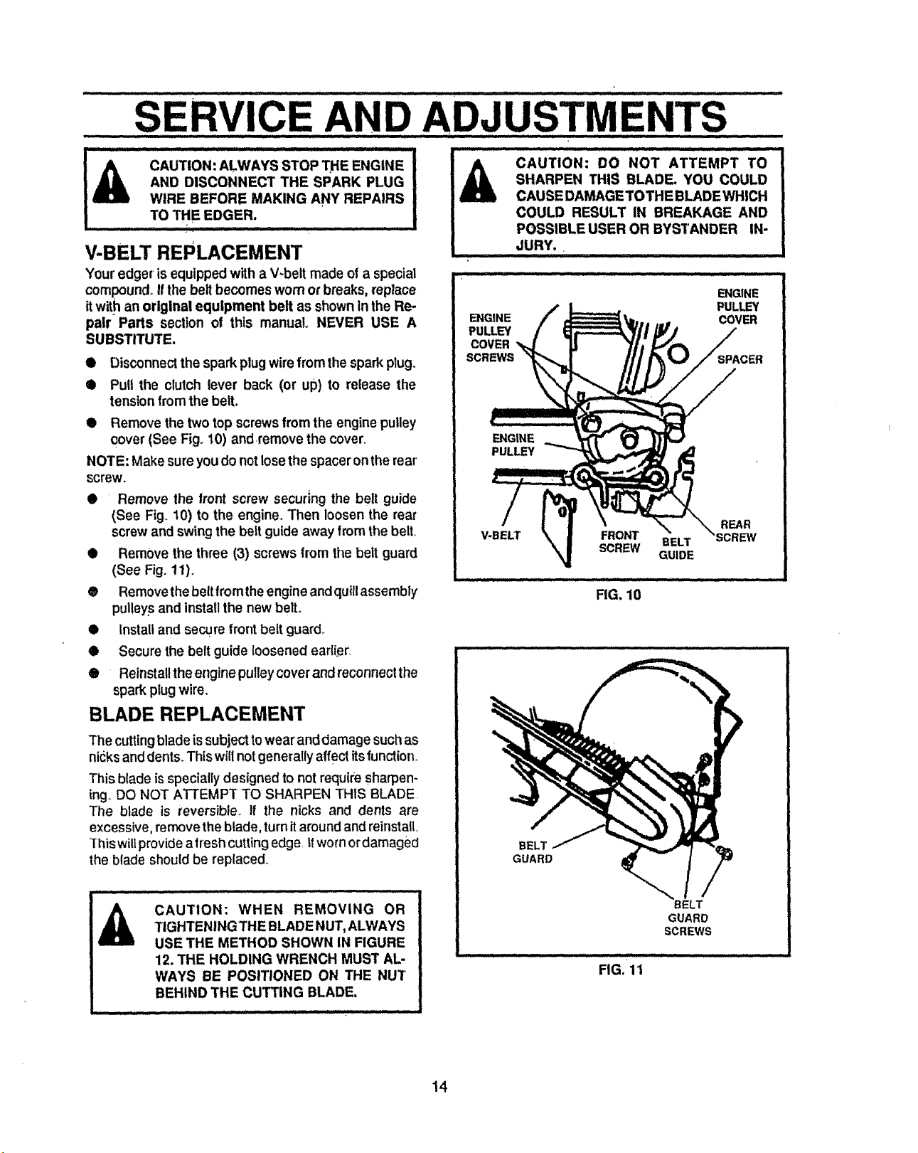
AIR CLEANER
Replace the filteronce a year; moreoftenunder dustyor
dirtyconditions°DO NOT attempt to clean or oll the air
filter,
To instalta new airfilter,dothe following:
e Disconnectthe spark plugwire from the spark plug.
e Turn the cover (See Fig.9) to the left (counterclock-
wise) andremove the cover and theairfilter from the
flanger
@ Discard the air filter.
e Clean the cover and the flange thoroughly_
e Insert the new air filter into the cover.
@ Push the cover firmly against the flange and turn itto
the right (clockwise) as far as itwilt go (See Fig,,9. Be
sure the retainers are locked around the flange,
• Reconnect fhe spark plug wire_
CAUTION: NEVER RUN THE ENGINE
WITHOUT THE AIR CLEANER ELEMENT
INSTALLED. A DEFECTIVE AIR
CLEANER CAN RESULT IN LOSS OF
ENGINE POWER AND CAN CAUSE EX-
CESSIVE WEAR OR DAMAGE TO THE
ENGINE COMPONENTS IF DIRT OR
Dus'r IS PERMITTED TO ENTER THE
ENGINETHROUGH THE CARBURETOR,
A DAMAGED AIR CLEANER, OR ONE
THAT ISCLOGGEDWITH DUSTOR DIRT
SHOULD BEREPLACED IMMEDIATELY°
IIIIIII IIII ii i i
FLANGE
FILTER
RETAINER
SLOT
TAB
FIG. 9
SPARK PLUG
Clean the spark plug and =reset the gap periodically.
Clean the area around the spark plug base, before
removal, to prevent dirt _[om entering into the engine.
Replace the spark plug if the electrodes are pitted or
burned or ifthe porcelain iscracked. Clean thesparkplug
bycarefully scraping the electrodes (do not sand blast or
usea wire brush). Be surethe spark plug iscleanand free
of foreign material. Check the electrodes gapwith awire
feeler gauge and reset to ,,035 if necessary. If a new
spark plug isneeded, refer to the Engine Operation and
Maintenance manual for the proper replacement spark
plug
Before reinstalling the spark plug, coat the threads lightly
with graphite or light oil to insure easy removal° Tighlen
the spark plug lirmly into the engine,, If a torque wrench
is available, torque the spark plug to 15 foot- pounds_
13
TURNCOVER
TOTHE _
(COUNTER.
CLOCKWISE)
TO REMOVE
COVER
TURN COVER
TO THE RIGHT
(CLOCKWISE)
TOINSTALL
"1
Page 14
SERVICE AND ADJUS rMEN rs
AND DISCONNECT THE SPARK PLUG |
CAUTION: ALWAYS STOP THE ENGINE I
WIRE BEFORE MAKING ANY REPAIRS |
............;toT,EEDGER....... i
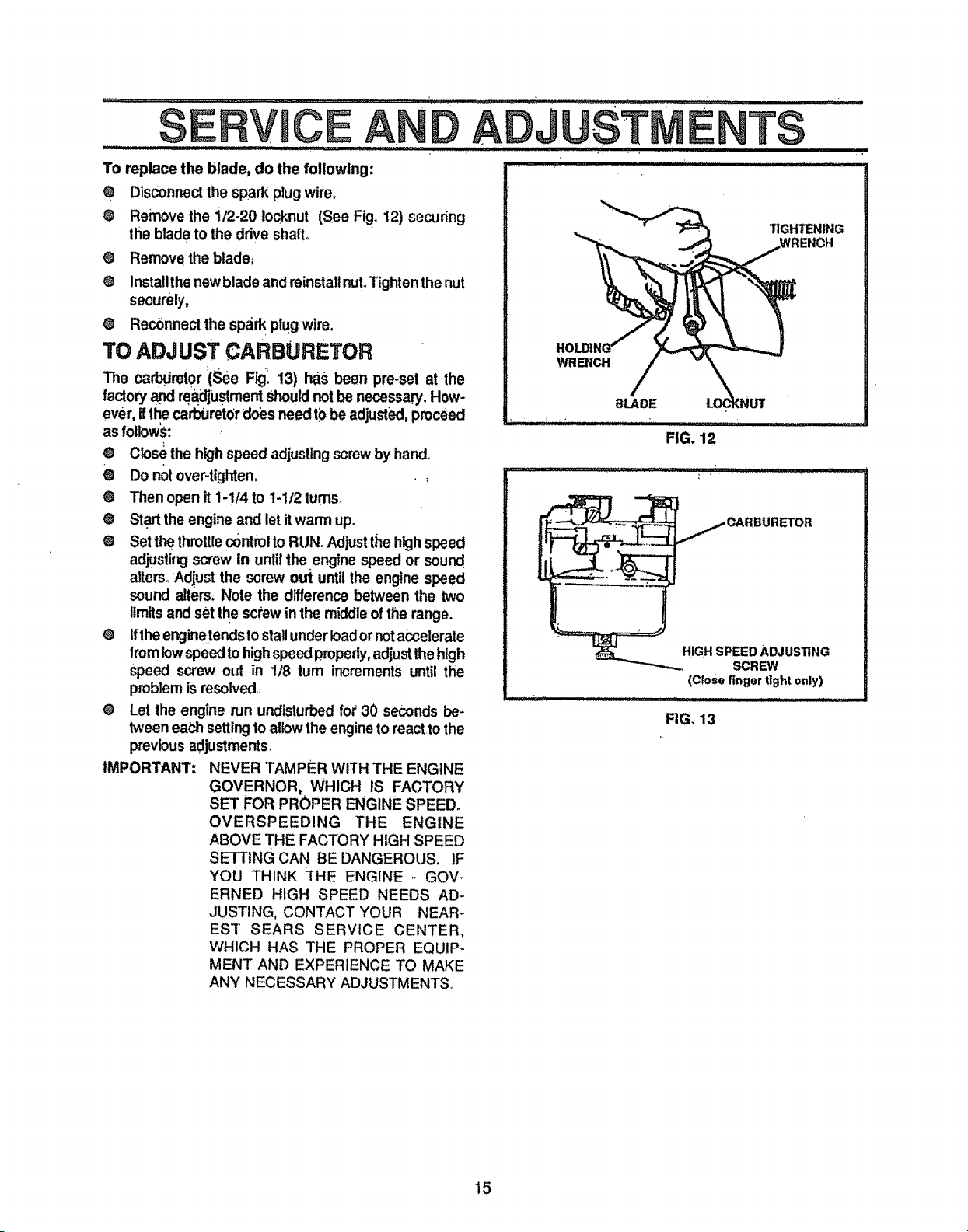
V-BELT REPLACEMENT
Your edger is equippedwith a V_beitmade of a special
compound°If the belt becomes worn or breaks, replace
itwith an original equipment belt as shown in the Re-
pair Parts section o! this manual. NEVER USE A
SUBSTITUTE.
@ Disconnectthe sparkplug wirefrom the sparkplug.
@ Pull the clutch lever back (or up) to release the
tensionfrom the belt.
• Remove the twotop screws from the engine pulley
cover (See Fig° 10) and.remove the cover.
NOTE: Make sure youdonot losethe spacer onthe rear
screw.
@ ' Remove the front screw securing the belt guide
(See Fig..t0) to the engine. Then loosen the rear
screw and swing the belt guide away from the bell
€ Remove the three (3) screws from the belt guard
(See Fig°11)o
@ Remove the belt from the engine andquill assembly
pulleys and install the new belt.
@ Install and secure front belt guard,,
@ Secure the belt guide loosenedeart[er_
® Reinstall the engine pulley cover and reconnect the
spark plug wire.
BLADE REPLACEMENT
SHARPEN THIS BLADE. YOU COULD
CAUTION: DO NOT ATTEMPT TO
CAUSE DAMAGETOTHE BLADE WHICH
COULD RESULT IN BREAKAGE AND
POSSIBLE USER OR BYSTANDER IN-
JURY,
_7 -- = I i iiiiiii iiii iiiiii iii jji !uii i1[ iii iii
ENGINE
ENGINE
PULLEY
COVER
ENGINE
PULLEY
V-BELT FRONT
SCREW BELT
GUIDE
PULLEY
COVER
REAR
RG. 10
The cutting blade is subject to wear and damage such as
nicks and dents_Th_swillnotgenerally affect its function,_
This blade is specially designed to not require sharpen-
ing_DO NOT ATTEMPT TO SHARPEN THIS BLADE
The blade is reversible,, if the nicks and dents are
excessive, remove the blade, turn itaround and reinstall
This willprovide atresh cutting edge, _!worn ordamaged
the blade should be replaced.
CAUTION: WHEN REMOVING OR
TIGHTENING THE BLADE NUT,ALWAYS
USE THE METHOD SHOWN IN FIGURE
12. THE HOLDING WRENCH MUST AL-
WAYS BE POSITIONED ON THE NUT
BEHIND THE CUTTING BLADE.
BELT
GUARD
ELT
GUARD
SCREWS
FIG, 11
14
Page 15
: :: : ,, _iiii,ii
SERVHCE
To replace the blade, do the following:
O Disconnect the spark plugwire.
Q Remove the 112-20 Iocknut (See Fig° 12) securing
the blade to ttie drive shall
O Remove the blade_
O Insta!lthe newblade and reinstall nutoTighten the nut
securely,
• Re_nnect the spark plug wire.
I':,,ADJUSTME
l'T_ j I I IIII I II III"I I JIII II 11111IIIUU
TO ADJUST CARBURETOR
The carl_Jretor'(See F_. 13) has been pre-set at lhe
factoryand rea_djustmentshouldnotbe necessary_How-
ever, ifthe carburetordoes need to be adjusti_l,proceed
as followS:
O Closethe high speed adjusting screwby hand.
® Do not over-tighten. .
O Then open it 1-!/4 to t-1/2 turns.
O Start the engine and let it warm up.
O Setthe.throttle c0ntiol toRUN. Adjust the high speed
ad_sting screw in untilthe engine speed or sound,
a_ers. Adiust the screw old untilthe engine speed
sound alters, Note the difference between the two
limits and set the screw in the middle of the range.
O Iftheenginetends to stallunder Ioador notaccelerate
fromlow speed toh_ghspeed properly,adjustthe high
speed screw out in 1/8 turn increments until the
problem is resolved.,
O Let the engine run undisturbed for 30 seconds be-
tweeneach setting to allow the engine to react to the
previous adjustments.
IMPORTANT: NEVER TAMPER WITH THE ENGINE
GOVERNOR, WHICH IS FACTORY
SET FOR PROPER ENGINE SPEED°
OVERSPEEDING THE ENGINE
ABOVE THE FACTORY HIGH SPEED
SETTING CAN BE DANGEROUS, 1F
YOU THINK THE ENGINE - GOV-
ERNED HIGH SPEED NEEDS AD-
JUSTING, CONTACT YOUR NEAR-
EST SEARS SERVICE CENTER.
WHICH HAS THE PROPER EQUIP°,
MENT AND EXPERIENCE TO MAKE
ANY NECESSARY ADJUSTMENTS,,
" " T$
i .......................
TIGHTENING
WRENCH
BLADE
FIG. 12
HIGH SPEED ADJUSTING
SCREW
(Close finger tight only)
FIG, 13
15
Page 16

i...... : .......... :: : : ..... _ : ::::: ' ...... .: .... + : + ii_+mlUimL111111¸¸¸
STORAGE
+ ...... ............. ........... : _ + ........ " ............. ENGINE
CAUTION: NEVER STORE YOUR
EDGER INDOORS OR IN AN EN-
CLOSED, POORLYVENTILATED AREA
IF GASOLINE REMAINS IN THE TANK
FUMES MAY REACH AN OPEN FLAME,
SPARK OR PILOT LIGHT FROM A FUR-
NACE, WATER HEATER, CLOTHES
DRYER, CIGAREI"r E, ETC.
....... : -: : +++ .
EDGER
0
Clean the edger thoroughly; remove all debris and
wipe the unit dry.
O
inspect the edger for worn or damaged parts and
tighten all loose hardware+
0
Oil allpoints described intheLubrlcatlon paragraph
in+the Customer Responsibilities section of this
manua!:
O
Store the edger in a protected area and cover for
additional protection+
IMPORTANT:
A YEARLY CHECKUP OR TUNE+UP
BY A SEARS SERVICE CENTER IS A
GOOD WAY OF ENSURING THAT
YOUR EDGER WILl. PROVIDE
MAXIMUM PERFORMANCE FORTHE
NEXT SEASON.
IMPORTANT: IT IS IMPORTANT TO PREVENT GUM
DEPOSITS FROM FORMLNG IN ES-
SENTIAL FUEL SYSTEM PARTS
SUCH AS THE CARBURETOR, FUEL
FILTER, FUEL HOSE, OR TANK DUR-
ING STORAGE, ALSO, EXPERIENCE
INDICATES THAT ALCOHOL-
BLENDED FUELS (CALLED GASO-
HOLOR USING ETHANOL ORMETHA-
NOL) CAN ATTRACT MOISTURE
WHICH LEADS TO SEPARATION AND
FORMAT!ON OF ACIDS DURING
STORAGE+ ACIDIC GAS CAN DAM-
AGE THE FUEL SYSTEM OF AN EN-
GINE WHILE IN STORAGE.
To prevent engine damage (ifedger:is not Usedfor more
than 30 days) followthe steps below,
• To remove gasoline, run the engine until the tank is
empty and the engine stops.,
O
ifyoudo not wantto remove gasbline, a fuelstabilizer
(such as Sears Craftsmanfuel stabilizer No+33500)
may be added to any gasoline left in the tank to
minimize gum deposits and acids, If the tank is
almost empty, mix stabilizer with fresh gasoline in a
separate container and add some to the tank+AL-
WAYS FOLLOW INSTRUCTIONS ON STABILIZER
CONTAINER. THEN RUN ENGINE AT LEAST 10
MINUTES AFTER STABILIZER IS ADDED TO
ALLOW MIXTURE TO REACH CARBURETOR.
STORE EDGER IN A SAFE PLACE. SEE WARN-
ING ABOVE.
O
Storethe edger inthe wheels-down, operatingposi-
tion. If the edger is stored in any other position, oil
from the crankcase could enter the cylinder, causlng
a service problem.
You can keep your engine in good operating condi-
tion during storage by:
• Changing oil+
O
Lubricating the piston!cylinder area, This, can be
done by first removing the spark plug and squirting
clean engine oil intothe spark plug holeoThen cover
the spark plug hole with a rag to absorb oil spray
Next, rotate the engine by pulling the starter'two or
three times. Finally, reinstallspark plug and attach
spark plug wire+
16
Page 17

TROU L SHOOTRNG
TROUBLE
Difficult starting
Englne runs erratic
Cutting blade falls to
turn
Blade fails to cut
properly
::: : :11111111
Excessive vibration
CAUSE
Stale fuel
Defective spark plug
Clogged fuel fil!er
Blocked.fuel line or empty fuel tank
Carburetor outOfadjustment
Fouledspark plug
........... i " ....................................
Clogged air cleaner.•.......... .
Jammed due to foreignobject
Looseblade
Defective V-belt
Defective quill bearings
Damaged or worn blade
= .
CORRECTION
..i..11111............
Drain fuel tank. Fillwilh fresh fuel
Clean and re-gap spark plug-.
r_l_l..i i.....i.ll...lll •. ....i,iiHi
Replace fue!filtero ' '
Clean fuel line;check gas tank.
:--.:-:- ".................. r;,,; " • ......................
Have caP'_Jretoradjusted.
C!ean and adjust gap.
Tap Cleanor replace air cleaner,
Clear obstruction,.
Tighten blade retaining nuL
Replace the V-belL
Replace the bearings.
,iirH LIH..',i.l.....Hii
Reverse blade or replace blade,
Stop engine immediaiely; tighten all bolts. If
vibration continues, take the unit into the
nearest SEARS Service Center_
17
Page 18

CRAFTSMAN 9"- 3 H.R EDGER 536.797540
ENGINE ASSEMBLY 13
12
1
\
I1
10
16
\
NOTE: ALWAYS USE ORIGINAL
EQUIPMENT PARTS Use of service/
replacement parts other than odginal
pads may void your warranty
REF.!
No. !
1
2
3
4 !
5 ,
6
7
8
9
PART NO.
331570
48148
314781
181608
120638
45602
32668
313011
320353
PARTNAME
Engine, Edger Tecumseh 3hp
Screw, 3/8-16 x 1..00
Pulley, Half V3L
Screw, 5/16-24x 1_00HHC
Washer, SPTLK _328x.60x,09
Washer, Flat o333x.87xolt9
Belt, V 4L 32_60LG
Screw and Washer Assembly
Retainer', Bell
REF.
NO.
10
1I
12
13
14
15
16
17
ALL UNNUMBERED
ITEMS ARE INTERCHANGEABLE
WITH OPPOSITE SIDE
PARTNO. PARTNAME
309300
181624
53407
173030
308237
315095
323534-854
308154-854
331585
Cover, Engine Pulley
Screw, 5/16-24x3.00 HHC
Spacer, Sleeve 335x.43x2.37
Screw, 5f16-24x3.75
Spacer, _3221D_562OD 80 TK
Spacer, Sleeve,335xA31x2.50
Frame, Assy Edger
Strap
Owner's Manual
18
!
t8
Page 19

CRAFTSMAN 9" - 3 H.P=EDGER 536.797540
FRONT WHEEL ASSEMBLY
REF°
NO.
1
2
3
4
PARTNO.
51796-854
180077
309902
1498
PART NAME
Arm, Front Wheel Support
Screw, 5/16-!8 x .75
Bolt, o500x°094 HHSH 5116-18
Nut, 5/16-18 REGHEXCTRLK
19
Page 20

CRAFTSMAN 9" - 3 H.P. EDGER 536.797540
N
GUARD ASSEMBLY
REF.
NO.
PARTNO.
1
320222
57072
2
3
120393
4
1498
5
308262
6
411666
7
1501
PARTNAME
Guard, Blade
Bolt, 5116-18x 63 CARR
Washer, Flat .344x 69x 065
Nut, 5116-18 REGHE×CTRLK
Guard, Belt
Screw, 10-16x ,50
Washer, tlat 203x °56 x .040
BLADE ASSEMBLY
9
1E0
11
\
\
8
REF._
NO_
1
2
3
4
5
6
7
8
9
10
11
PARTNO.
120396
308539
308254
1499
308243
411666
336391
315233
412281
20562-853
46023
PART NAME
Washer, Flat .531 x 1.06x .095
Quill Supportt Assembly
Bolt, 500 x 3275 HHSH 318_16
Nut, 3f8-16 REGHXCTRLK
Delfector, Rubber
Screw, 10-16x ,50
Quill Assy, Large Suppoit
Spring, compression
Pin, Spring _250DIAx1.00LG
Blade, Edger 9"
Nut, 12-20 WDFL
20
Page 21

CRAFTSMAN 9"- 3 H.P. EDGER 536.797540
DECALS
\
REFo
NO,
1
2
3
4
5
6
PARTNO.
69711
332077
324860
324475
324476
312548
PARTNAME
Decal, InformationDANGER
Decal; 3°0 HP
Edger/Craltsrr
Decal, Blade F , Edger
Decal, Dangel Blade, Edger
Decal, Warning, Edger Blade
Decal, Quadrant Setector
3
/
!
21
Page 22

CRAFTSMAN 9"- 3 H.R EDGER 536;797540
HANDLE ASSEMBLY
7
3
7
i8
REF.
NO.
1
2
3
4
5
6
PARTNO,
308253-853
580292-853
310146-853
51333
1498
180081
36368
1498
I
'4
PARTNAME
Handle, Lower
Rod, Control 25 65 LG
Handle, Upper
Screw, 5116-18 x ,63
Nut, 5/16-t8 REGHXCTRLK
Screw, 5/16-18xl _25
Pin, Hair ,072 DIAx 1,i3LG
Nut, 5t16-t8 REGHXCTRLK
22
Page 23

CRAFTSMAN 9" - 3 H.P. EDGER 536.797540
DEPTH ADJUST HANDLE ASSEMBLY
12
6
9
12
REF TO
UPPER
REF.
NO.
!
2
3
4
5
6
7
8
9
t0
1t
12
PARTNO.
310052-853
180024
1502
310050-853
180081
25644
1498
56924
310053
1499
311670
1498
PART NAME
Plate, Sector
Screw, t/4-20xl,25 HHC
Nut, 1/4-20 REGHEXCTRLK
Handle, Depth Adiust
Screw, 5/16-18xlo25 HHC
Spdng
Nut, 5/16-18 REGHEXCTRLK
Grip, Hand r75x425
Stud
Nut, 3/8.16 REGHXCTRLK
Strap, Lever
Nut, 5/16-18 REGHEXCTRLK
23
Page 24

CRAFTSMAN 9"- 3 H.P. EDGER 536.797540
WHEEL ASSEMBLY
3
3
Ho. i pARTNO.
331578
,23763
3 41529
4 21882
i
/
1
PARTNAME
Tire & Rim Assembly
Bolt, 500xl .39 HHSH 3/8-16
Nut, 3/8d 6 Jam Nut
Spacer Sleeve .406x _83x.375
24
Page 25

CRAFTSMAN 4-CYCLE ENGINE MODEL NUMBER: 143.953005
131
' \_,_t1_1
f-
312
.224 172
\
238 _.s _"
171
209
ze5 92
93
ze?/
_q
25
Page 26

CRAFTSMAN 4-CYCLE
REF.
NO.
t
2
14
15
!6
17
18
19
20
25
25A
26
26A
3O
40
40
4O
41
41
4t
42
42
42
43
+45
46
48
49
50
60
65
69
70
72
75
80
81
82
83
86
89
90
92
93
100
lo2
103
t10
t19
120
125
125
126
126
130
13t
132
135
PART NO.
0
0
36560
26727
28277
31334
31336
31335
65O548
34593
32600
36552
35883
650802
65O926
359O2
34514
34515
34516
32538B
32548B
32549B
28986
28987
28988
2O381
30963B
32610A
27241
28594
33149A
29745
65O128
27677A"
35863A
27642
26208
30574A
30590A
30591
30588A
650488
610961
611195
65O815
650816
34443A
650872
650814
35182
36437"
36438
36471
36472
29314B
29315C
650694A
6021A
850708
33636
RPM Higl_3300 tO3600
RPM Low t700 to 2000
Cyclinder (tnc+2,20,72;&125)
Dowel Pin
Washer
Governor Rod
Governor Lever
Governor Lever Clamp
Screw 8+32 x 5/16+"
Extension Spring
oi! Seal
Blower Housing Baffla(tnc 262)
Baffle Extension
Screw t/4-20x5/8"
Screw 8-32x21/64"
Crankshaft
Piston, Pin & Ring Set iStd)
Piston, Pin & Ring Set (,.010" OS)
Piston, P+n& Ring Set (°020" OS)
Piston& Pin Assy (Std)(Inc. 43)
Piston & Pin Assy (.010" OS}(Inci 43)
Piston & Pin Assy (.020" OS)(Inc143
Ring Set (Std)
Ring Set (+010" OS)
Ring Set ( 020" OS)
Piston Pin Retaining Ring
Connecting Rod Assy
(IncL 46 & 49)
Connecting Rod Boli
Valve Lifter
Oil Dipper
Camshaft (BCR)
Blower Housing Extension
Screw 10-24xl/2"
Cylinder Cover Gasket
Cyctinder Cover (Incl..75-83 311&31;
Oil Drain Ptug
Oil Seal
Governor Shaft
Washer
Governor Gear Assy (!ncL 8!)
Governor Spool
Screw, 114-20x 1+1/4"
Flywheet Key
Flywheel
Belleville Washer
Flywheel Nut
Solid State Ignition
Solid State Mounting Stud
Screw, Torx T+15, 10-24x1
Ground Wire
Cylinder Head Gasket (Kit)
Cylinder Head (Inci t30)
Exhaust Valve (Std) (lncf 151)
Exhaust Vafve (!/32" OS) (Inc] 15t)
Intake Valve (Std)(lnc1151)
Intake Vatve (1t32"OS (inc1151)
Screw, 5116-18x2"
Screw, 5/16+18x1+1/2"
Washer
Resistor Spark Plug (CJ+8)
PART NAME
ENGINE MODEL NUMBER: 143,953005
REF°
p
NOTE: This engine could have been built with 590688 starter
Refer to the design of the air intake louvers for part identifica-
tion. Individual stadet parts do not interchange
PART NO,
150
31672
t511
31673
169
27234A"
170
27666
171 .
3141O
172
34146
173
35350
174
30200
178
29752
179
30593
182
6201
184
31688A*
t85
345.97
186
31341
20O
33858A
203
31342
20;_
650549
206
610973
209
650139
2o9A
30322
215
3241O
223
65O451
224
32649A*
238
650932
239
34338
241
35797
245
35066
250
35065
260
35585
262
65O737
274
3008tA*
275
30996
277
650493
285
36467A
287
650926
290
29774
292
26460
298
650665
3OO
32660A
301
35355
311
27625
3t2
29673 °
31.3
34080
327
35392
339
28212
340
32661
342
650751
345
32664
370A
36261
370B
35703
370C
36501
380
632589-
390
59O732
40O
36439
includes 26754A, 26756, 27234A, 27272A, 27677A,
29673,30081A, 31688A+36437+
Valve Spring
Valve Spring Cap (Kit}
Valve Cover Gasket
Breather Body
Breather Element
Valve Cover
Breather Tube
Screw 10+24x9/16"
Nut & Lock Washer 1/4-28
Retainer Clip
Screw 1/4-28x7t8"
Carburetor To Intake Pipe Gasket
intake Pipe
Governor Link
ControlBracket (tnci 203,204,206
209,209A)
Compression Spring
Screw 5-40x7t16"
Terminal
Screw 8+32x1!2"
Locknut8+32
ControlKnob
Screw 1t4+20x1"
Intake Pipe Gasket (Kit)
Screw 10-32,_49/64"
Air Cleaner Gasket (Kit)
Air Cleaner Collar
Air Cleanre Filter
Air Cleaner Cover
Blower Housing
Screw 1/4+20xt/2"
Exhaust Gasket
Muffler
Screw tt4-20x 1-314"
Starter Cup
Screw 8-32x 21t64"
Fuel Line
Fuel Line Clamp
Screw 1/4.15x7/8"
Fuel Tank (IncL 292 & 301)
Fuel Cap
Oil Fill Plug (lncl+312)
Oit FillP_ugGasket (Kit)
Spacer
Starter Plug
Spacer
Fuel Tank Bracket
Screw, 1/4-20x7116"'
Heat Baftie
Lubrication Decal
Control Decal
Primer Decal
Carburetor (lnci 184)
Rewind Starter
Gasket Set (lncl items marked ")
PART NAME
26
Page 27

CRAFTSMAN 4-CYCLE ENGaNE MODEL NUMBER: 143.953005
CARBURETOR NO. 632589
REF:I
NO. I
6 I
I6 I
25 I
27 I
28 I
29 I
PART NO.
635289
631615
631767
631184
631183
63259O
6505O6
832164
631867
631024"
632019
63t028"
PART NAME
Carburetor
(Inct 184 of Engine Parts List)
Throttle Shaft & Lever Assy
Throttle Return Spring
Dust Seat Washer
Dust Seal (Throttle)
Throttle Shutter
Shutter Screw
Fuel Fitting
Float Bowl
Float Shaft (Kit)
Float
Float Bowl "0" Ring (Kit)
27
REF.
NO ....
30
31
35
35A
40
41
42
43
44
48
6O
PART NO. PART NAME
631021°
631022
36045
632647
632591
63O74O"
630739
63O736
27110"
631027'
632592
inletNeedle, seat, & Clip (lnc131)
Spring Oflp
Primer Bulb/Retainer Ring
Primer Bulb Filter
Main Adj. Screw Assy (lncl 41 thru 44
High Speed Mixture Screw "O" Ring
High Speed Mixture Screw Washer
High Speed Mixtbre Screw Tension
Spring
Bowl Nut Washer (Kit)
Welch Plug, Atmospheric Vent (Kit)
Repair Kit(tnct Items Marked ")
Page 28

CRAFTSMAN 4-CYCLE ENGINE MODEL NUMBER: 143.953005
RECOIL STARTER 590732
11
/
13
_8
7 _ _,_7
REF'
NO.
o
2
3
4
5
6
7
8
1t
12
13
_3
PARTNO_ PARTNAME
590732
590599A
59060O
590696
590601
590697
590698
590699
590700
59O695
590535
59070t
Rewind Starter
Spring Pin (]ncl 4)
Washer
Retainer
Washer
Brake Spring
Starter Dog
Dog Spring
Pufley & Rewind Spring Assy
Starter Housing Assy(40 degree
grommet)
Starter Rope (lg 98"x9/64" dia)
Starter Handle
4
28
Page 29

CRAFTSMAN 4=CYCLE ENGINE MODEL NUMBER: 143.953005
RECOIL STARTER 590688 (OPTIONAL)
REF.
PART NO,
NO.
....590688 .........RewindStader
o
t
590599A
2
59O60O
3
590615
4
590601
590598
5
6
590616
7
59O617
8
590618
lO
590620
tl
59O687
59O535
12
13
590701
PART NAME
Spring Pin (tncl 4)
Washer
Retainer
Washer
Brake Spring
Starter Dog
Dog Spi'ing
Pulley Assy (lncl. 9 & 10)
Spring Cover
Starter Housing Assy(40 d
grommet)
Starter Rope (lg 98"x9/64
Starter Handle
29
Page 30

: : ............ -- ,,',, .... ,;,,,,,,,,,,,,,, ........................ .. ,....... _ H
CRAFTSMAN
OWNER'S
MANUAL
MODEL NO.
536.79754O
HOW TO ORDER
REPAIR PARTS
3 HORSEPOWER
9 INCH
EDGER
Each EDGER has itsown MODEL NUMBER on
a model plate on the frame behind the engine.
Each ENGINE has its Own MODEL NUMBER
found on the BLOWER HOUSING.
Always mention these MODEL NUMBERS when
requesting service or Repair Parts for your
EDGER.
All parts listed herein may be ordered through
any Sears Service Ce nter/Departments and most
Sears Stores,
WHEN ORDERING REPAIR PARTs, ALWAYS
GIVE THE FOLLOWING INFORMATION:
* PRODUCT- "EDGER"
* MODEL NUMBER - 536.797540
"ENGINE MODEL NUMBER - 143.953005
* PART NUMBER
* PART DESCRIPTION
'Your Sears merchandise has added value when you
consider that Sears has service units nationwide staffed
with Sears trained technicians, Professional technicians
specifically trained on Sears Products, having the parts.
tools and equipment to ensure that we meet our pledge
toyou,,,,weservice what we sell,,"
.................................................. :........... _ i,,iml : lllll,ll, I II
SEARS, ROEBUCK AND CO., Hoffman Estates, IL 60179
331585 t2/02/94 Printed in U,S.A.
Page 31

UAL
MODELO NO.
536.797540
Precaucibn:
Leay sigatodas Uas
reglase instrucciones
de seguddadantesde
operareste equipo
SEARS, ROEBUCK AND CO., Hoffman Estates, IL 60179 ESTADOS UNIDOS
3 CABALLOS DE FUERZA
9 PULGADAS
CANTEADORA
°Montaje
oOperacibn
• Responsabilidades del C|iente
°Servicio y Ajustes
° Partes de Repuesto
Part No 3315850
Page 32

REGLAS DE SEGURIDAD
PRECAUCION: SIEMPRE DESCONECTE EL ALAMBRE DE LA BUJtA Y PONGALO EN
DONDE NO PUEDA ENTRAR EN CONTACTO CON ESTA PARA EV1TAR EL ARRANQUE
POR ACCIDENTE DURANTE LA PREPARACION, EL TRANSPORTE, EL ,_JUSTE O
CUANDO SE HAGAN REPARACIONES
ANTESDECADA USO
Q Lea el manual del dueSocuidadosamente. Familiaricese
completamentecon loscontrolesyconetuso adecuado de
la canteadora. Sepa c6mo pararla y desenganchar los
controlesr&pidamente.
• No opere la canteadora sin user ropeexterior adecuada.
Use zapatos que mejoren el equilibrtoen las superficies
resbalosaso
eli Mantenga el &rea de operad6n despejada de toda la
genre, especialmente, los niSospequeSosy losanimales
dom_sticos,.
• Inspeccione cuidadosamente el _Pea en donde se va a
userla canteadora y remueva todoslos objetosextra_os
SEGURIDAD DEL COMBUSTIBLE
Q Maneje el combustibte con cuidado; es altamente
inflamabie_
• Use un envase adecuado,
O
Revise el sumtnistrode combustibleantes de cada uso,
permittendoque exfsta espaciopare la expansionpues el
calor del motory!o sol pueden hacer que se expanda el
combustible.
O
Uene el estanque de combustible afuera con mucho
cuidado_ Nunca Ilane el estanque de combustible en
recintoscerrados_ Vusiva a colocar ta tapa del estanque
de combustible en forma segura y limpie el combustible
derrama.do,
• Nunca remueva la tapa del estanque de combustible o
agregue combustiblea un motorque est_ funcionando o
que est_ ¢altente.
• Nunca almacene combustible o la canteadora con com-
bustible en el estanque dentro de un ed_cio en donde los
gases pueclan aJoanzar una llama exPuesta.
SEGURIDAD DE OPERACION
• Nunca permitaqua los nihoso adolescentes j6venes
operensucanteadora,Mant_ngalosalejadoScuandoest6
en operacl6n,Nunca permitaque losadultosoperenIs
canteadora!recortadorasinlosconocimientosadecuadgs,
• Siempreusaanteojosde seguridado proteccionespare
los oJosdurantela operaci6no cuandohaga ajusteso
reparacionaspareprotegersusojoscontraobjetosextra_os
quelacanteadorapuedalanzar,
e, Nopongafasmanosnilospiescercao debajode partes
rotatorias_
• Tenga sumo cuidado cuando opere o atraviese entradas
de autom6viles deripio, senderosocamlnos. Mant_ngase
alerta de peligros escondidos otr_ficoo
• Tenga cuidado para evitar resbalarse ocaerse..
• Nunca opere la canteadora sin las protecciones y tas
planchas adecuadas, o sin otrosdispositos de protecci6n
de la seguridad en su lugar.
® Nunc.aoperelacanteadora aaltas vsiocidadesde transporte
ensuperficiesresbalosas_ Mirehactaatr_sytenga cuidado
cuandoretrocedao
• Nunca permtta la presencia de espectadores cerca de la
canteadora.
• Mantenga a losnifos y alos anlmalesdom_sticos atejados
mientras se est_ en operaci6n.
• Nunca opere la canteadora sir]buena vtsibilidado luz_
• No haga funcionar el motor en rectntos cerrados. Los
gases de escape son peligrosos(confienen MONOXtDO
DE CARBONO, UN GAS SIN OLOR QUE CAUSA LA
MUERTE).
• Tome todas las precauciones posibles cuando deje fa
canteadoradesatendida. Pare el motor,
• No sobrecarguela capacidadde laeanteadora tratandode
cantear muy profund_mente a mucha velocldad.
ALMACENAMIENTO CON SEGURIDAD
• Siempre refi_rase ala seccl6n de almacenamiento del
manualdelduefiopare verfficar!osdetatles de importancia
silacanteadora/recortadoraseva aalmacenar porunlargo
perfodode tiempo_
• Nunca almacene ta canteadora/recortadoracon combus-
tible en elestanque de combustible dentro de unedificioen
donde se encuentren presentesfuentes de ignici6n, tales
como los catentadoresde aguao del amblente, secadoras
de ropeyotros artefactosparecidos. Permita que seenfr[e
el motorantes de guardarloen alg0n lugar cerrado.
• Mantenga la canteadora/recortadora en condiclones de
trabajoseguras. Revise todoslos sujetadores a inter€aloe
frecuentes para ver_icar si est&n apretados en forma
segura.
SEGURIDAD DE REPARACIONESIAJUSTES
• Despu,_s de pegarle a obJet0s extraSos, pare el motor.
Remueva el alambre de labujia, y mant6ngalo alejado de
6sta para evitar at arranque por accidente, Inspeccione
cuidadosamente la canteadora/recortadora pare veri|icar
si est& daSada y repare los dafios antes de vofver a
arrancar yoperar la canteadora/recortadora.
• Si la canteadoratrecortadora empieza a vibrar
anorma[mente, pare el motor y revise inmedtatamente la
cause. Lavibraci6n,normalmenteesunavisode problemas.
@ P_velacuchillacuando abandonelaposici6nde operaciSn
Tambi_n, pareelmotor ydesconecte el alambre de tabuifa
antesdedestaponar lacuchillay cuandohagareparaciones,
a,_usteso inspecciones_
• Cuando haga fimpiezas, reparaciones o inspecciones,
apague el motor y asegfirese que todas las partes en
movim!ento se hayan detenido
Q Nunca trate de hacer ajustes mientras el motor estd
funcionando (excepto cuando espec|ficamente Io
recomiendeel fabricante).
2
Page 33

FELIClTAClONESperla compradesuCanteadora!
RecortadoraCraftsmanSears..Hasidodisehada,planificada
y fabricada para darte ta mejor confiabilidad y el mejof
rendimiento posibles
En el caso de que se encuentre con cuaiq uierprobtema que no
pueda solucionar f&citmente, haga el favor de ponerse en
contacto con su Centro/DepartamenEo de Servicio Sears m&s
cercano Sears cuenta con tecnicos bien capacitados y
competentes y con {as herramientas adecuadas para darle
servicio opara reparar esta unidad _
Haga el favor de leer y de guardar este manual Estas
instrucciones le permitir&n montar y mantener su canteadora;
recortadora enforma adecuada. Siempre observe Ias"REGLAS
DE SEGURIDAD.."
NUMERO DE MODELO 536.797540
ESPECIFICACIONES DEL PRODUCTO
C BALLOSDEFUERZA: ,p
DESPLAZAMIENTO "
9,06 pulgadas
cuadradas
(148 c,c )
CAPACIDAD DE
GASOLINA
LuBRIOAOION:
1,0 cuartos
Sin plomo
(regufar)
20 oz
SAE 30W
NUMERO DE SERIE
FECHA DE COMPRA
EL NUMERO DEL MODELO Y EL DE SERIE SE
ENCUENTRAN EN LA CALCOMANIA EN ELBASTIDOR
DE LA CANTEADORNRECORTADORA, DETRAS DEL
MOTOR.
DEBE REGISTRAR TANTO EL NUMERO DE SERIE
COMO LA FECHA DE COMPRA Y MANTENERLOS EN
UN LUGAR SEGURO PARA REFERENCIA EN EL
FUTURO.
ACUERDO DE MANTENIMIENTO
Este producto incluye un Acuerdo de Mantenimiento Sears
Pbngase en contacto con su tiend_ Sears m&s cercana para
informarsesobre losdetalles.
I lU I
BUJIA: Champion
(ABERTURA 0°030 pulg,,) CJ-8 o equivalente
RESPONSABILtDADES DEL CLIENTE
e
Lea y observe las reglas de seguridad
®
Siga unprogramaregular de mantenimienlo, cuidado y uso
de su canteadora/recortadora
O
Siga las instrucciones descritas en las secciones de
"Responsabilidades del Cliente" y "Almacenamiento" de
este Manual det DueSo
GARANTIA LIMEADA DE UN Ai O PARA LA CANTEADORA/
RECORTADORA CRAFTSMAN
Pot uno,_5o a partirdela fecha de compra, cuando esta Canteadora/Recortadora Craftsman se mantenga, iubrique y afinesegun
las instruccionesen el manual del dueSo, Sears i'eparar&, gratis, todo defecto en el material y la mano de obra
Si laCanteadoralRecoriadora Craftsman se usa para fines comerciateso de arriendoo est& garantia se ap_ca solo por 90 dies,
a partir de la fecha de compra
Esta garantia no cubre Io siguiente:
@ Articu!os desgastables que se desgastan durante et us0 normal tales como las buj{as, etc
@ Reparaciones necesarias debido al abuso o a {a negligencia del operador, incluyendosea los cigueSales doblados y a la
lalta de mantenimiento del equipo segun las instrucciones que se encuentran en el manual del dueSo
EL SERVIClO DE GARANTiA ESTA DISPONIBLE AL DEVOLVER LA CANTEADORA/RECORTADORA CRAFTSMAN AL
CENTRO/DEPARTAMENTO DE SERVICIO SEARS MASCERCANO EN LOS ESTADOS UNIDOS ESTA GARANTIA SOLO
SE APLICA CUANDO ESTE PRODUCTO SE USA EN LOS ES'TADOS UNtDOS
Esta Garant{a le otorga derechos legales espec{ticos, y puede que tambi_n tenga olros derechos que varian de estado a estado
SEARS, ROEBUCK AND CO, DepartamentO D1817 WA, Hoffman Estates, LL60179
ADVERTENCiA: Esta unidad viene equipada con un motor de combustion interna y no se debe user sobre, o cerca, deun terreno
no desarrollado cubierto de bosques, de arbustos o de c6sped, a menos que el sistema de escape de!motor venga equipado con un
amortiguador de chispas que cumpla con fas leyes focales o estatales (si existen) Si Seusa un amortiguador de chispas, etoperado;
debe mantenedo en condicionesde trabajo eficientes
Enel estado de Cati|omia, taiey exige 1oanterior (Secci6n 4442 del"California Public Resources Code" (Decrelo de Recursos Publicos
de California)),. Otros estados pqeden contar con otras leyes parecidas. Las {eyesfederales se aplican en Ias tierras {ederales Su
Centro de Servic]o Autorizado Sears m&scercano tiene disponibfe un amortiguador de chispas/silenciador (yea la seccion "PARTES
DE REPUESTO" en este manua!)
3
Page 34

CONTENIDO
REGLAS DE SEGURIDAD .......................... 2
ESPECIFiCAClONES DELPRODUCTO ..... 3
RESPONSABILIDADES DEL CLIENTE ........
.......................................... ................ 3,12,13
GARANTIA ................................................. 2
CONTENIDO .................................................. 4
CONTENIDO DEL PAQUETE CON
ARTICULOS DE FERRETERIA .................. 5
MONTAJE ............................................... 6-7
A
Ajustes:
Carburador .................................... 15
Montaje ................................................6-7
B
Correa:
Rernocl6n/cambio ........................ 14
CuchiUas:
Afilamtento ................................14,15
C
Ajuste del Carburador.................... 15
Listade Revision
Operact0n .................................... 7
Maintenance................................12
Palanca del Embrague ........._.......8,9
Controles, canteadora ..................8,9
Slatar ia Acera ................................. 9
Responsabilidades,dal Cliente..........
.........•...................................... 3,12,13
Recemendaciones Generafes,_ 12
Lubrication ............................12,13
Canteadora........................;..........12
Motor ................................... 12,13
Bujfas ............................................13
Motor:
Cambio de aceite ............... i....... 13
Nivel de aceite ..................................12
Tipo de aceite .............................3,9,t2
Preparacl6n ................................. 9
Armnque ..........................................1t
Almacenamiento...........................16
Consejos para Canteadora ............11
Combustible:
Tipo ................................... ;............9
Almacenamiento....................'.............16
Recomendaciones Generates ...... 12
Lubricaci0n:
Canteadora .................................. 12
Motor .................................... 12,13
Aceite:
Condiciones de clima fr[o ..........9,12
Motor ...................:................... 9,12
Almacenamiento ......................;........16
Tipo .........................................3,9,12
OperactSn................................... 8-11
OperaciSn de la canteadora ..............9
INDICE
E
F
G
L
O
OPERACION ......................................... 8-11
SERViCIO Y AJUSTES ........................ t 4-15
ALMACENAMIENTO .................................... 16
IDENTIFICACION DE PROBLEMAS ........ 17
PARTES DE REPUESTO
(CANTEADORA) (VEA EL INGLES) .... 18-24
PARTES DE REPUESTO
(MOTOR) (VEA EL INGLe:S) ............... 25-28
ORDEN DE PARTEStSERVlCIO. Contratapa
P
Bolsa con laspartes ............................5
Bot0n det cebador..........................8,9
Especificaciones det producto ...........3
R
Partesde repuesto (Yea el manual del
due¢=oen ingt_s) ............................18-28
S
Reglas de seguddad ........................ 2
Servicioy Ajustes ...........................14-15
Ajuste del Carburador .....................14
Correa:
Remoci6n/carnbio..................14,15
Especificaciones................................3
Arranque del motor ...............................11
Parada del tractor ................................9
Almacenamiento ................................16
T
Contenido ..........................................4
Llantas ................_'.................................9
Puntos para la identificacidn de
pmblemas .........................................17
W
Garantfa ..................................................2
4
Page 35

i i L i ............ ,,,,....................................................
CONTENIDO DEL PAQUETE CON ARTICULOS DE FERRETERBA
Contenido de la bolsa con las partes, mostradas del tafio real a menos que se indique
4 - Tom Ilos de brida ancha de
cabeza hexagonal de
5!16-1"8x 5t8 pulg_das
8 * Tuercas de cabeza
hexagonal de 5/16-t8
2 - Torn]llos de cabeza hexagonal
de 5!16-18 x 1-1/4 pulgadas
G
4 - Espactadores (conjunto de la
tueda trasei'a Izqulerda)
Partes empaquetadas en forma separada en la caja de cart6n (no se muestran del tamafio real)
3 - Tuercas de cabeza
hexagonal 3t8-16
2 "Horqulllas
Manual del Duefio
1
f
I
I
I
2 - Bolss con las partes
I
t
1
I
I
(3) ;Rue_a
(1) ,Mango Inferior
I
I - Varilla de control
(1) -Mangos superiores
Page 36

MONrAJE
............ ,....................... _ ,,,,,,,,_,,,,,,,,,,,_,,_ .... ,,..... ,......... ........ .. ..............
HERRAMIENTAS NECESARIAS PARA EL PARA MONTAR LA CANTEADORA
MONTAJE • Ponga etmango inlerior dentro delbastLdordetacanteadora
1 - Ltave de3/4 pulgada (o !lave ajustable) (vea la Fig. 3A) y aseg_relo en su lugar con cuatro (4)
2 - Llaves de !/2 putgada (o llaves ajustabtes) torniItos de brida ancha, de cabeza hexagonal de5!16-18
1- Par de alicates ycuatio (4)tuercasdeseguridad,decabezahexagonatde
1 - Desatotnillador regular 5/16-18 (qua se encuentran en _abolsa con las partes).
2 _ Liave de 9116pulgada (o I_avesajustables) Sujete el mango inferior hacia atr&sa medida que aprieta
lostomitlos.Lastuercasde seguddadse deben encontrar
La Figurai muestra la canteadora completamente montada
Lasreferendasalladoderechoyallado izquierdo delacanteadora
son desde laposidSn deloperador detrAsde la unidad
PARA REMOVER LA CANTEADORA DE LA
CAJA DE CARTON
• Remueva el mango inferior de la caja de cart6no
• Remueva la varifla de control de la caja de cartdno
o Remueva el mango superior y el material de empaque de la
caja de cart6n,
• Remueva las ruedas, la bolsacon faspartesy el material de
empaque de lacaja decart6no
• Corte las cuatro esqutnas de la caja de cartSn_
• Remueva el empaque de la cuchiHade la canteadora
en la parte interior de los dos mangos, segSn se muestra
en la Fig. 3A
O
Adjunte cada rueda trasera, segQn se muestra, ala
canteadora (yea la Fig. 2) con un perno con resalto de 3/
8-16 x t ,390pulgadas, elespaciador y latuerca de cabeza
hexagonalde 31B-16(que se bncuentran en la bolsa con
tas partes).
,, ....... i
L i SEGURIDAD O PROTECCION PARA LOS |
OJOS CUANDO MONTE LA CANTEADORA,
I ..... ............... I
MANGO PALANCA DEL
SUPERIOR
VARILLA DE
PROTECCtONDE
LACUCHILLA
MANGO DEL
ARRANCADOR
FIG, 2
Q
Adjuntela rueda delantera, segOnse muestra, en la parte
exterior de tacanteadora (yea la Fig. 1)con-un perno con
resattode 3t8-.16x 1,.390puigadas y unatuerca decabeza
hexagonal de 3/8-16 (que se eneuentran en la bolsa con
las partes)
........._,,,,,,,,,,,,_, _ --
FIG, 1
_IILL
FIG. 3A
Page 37

TAJE
O Ponga e] mango superior en e] mango inferior (yea ]a Fig
4), alineeelmango superior con losdos agujeros superiores
en el mango inferior y aseg{Jreto en su fugarcon quatre (4)
tornit!os de cabeza hexagonalde 5/16+18x t +t/4pulgadas
yquatre (4) tuercas de seguridad, de cabeza hexagonal de
5/16+18(que se encuentran en [abolsa con laspartes) Las
tuercas de segur]dad se deben encontrar en la parte
interior de los dos mangos, seg_Jnse muestra en +aFig 4
O fnserte un extremo de la varilla de control, desde la
izquierda a la derecha, a tray,s del agujero en ta patanca
del embrague (yea ta Fig,,4) y adjuntelo con una horqui!ta
(que se encuentra en {aboisa con Ins partes)
O Ponga la palanca de{ embrague en la primera profundidad
selecctonabte (yea Ia Fig, 4) e inserte el otto extremo de la
varitla de control a travEs del agujero del brazo de soporte
del cuerpo (vea la Fig, 4)° Adjt_ntela con la horquLtla(que
se encuentra en la bolsa con las partes)
• Mueva la palanca delembrague a la posiciEn m_s trasera
posibte (NEUTRO)y aseg_rela. Vea elaviso acontinuaciEn
AMISO: En el caso de que sea dificil hacer que la palanca del
embrague se meta en NEUTRO, puede set necesario soltar !os
cuatro tornilfos y tuercas que sujetan Ios mangos inferiores al
bastidor (yea la Fig.. 5). Pafanquee (hacia adelante) los man-
gos, sElo lo suficiente parapermitir que Ia patanca del embrague
entre libremente a la posici6n de NEUTRO Vuelva a apretar
Ins tuercas y ios tornillos Cuando la palanca del embrague
est,_ en la postci(_}n de NEUTRO eL Brazo de Soporte de1
Cuerpo tiene que estar en contra del espaciador y del lornillo
delr_s de 6ste (vea la figura insertada dentro de la Fig 4)
MANGOS SUPERIORES
N LA POSICION
E OPERACION)
PBOFUNDIDAD
SELECCIONABLE
TUERCASDE
SEGURIDAD DE
CABEZA
DE5116-18
BRAZO DE
SOPORTE
DELCUERPO
TORNiLLOS
DE CABEZA
HEXAGONAL
DE5t16_18
EMBRAGUE
HORQUILLA
DEL
CUERPO
_J LISTA DE REVISION
ANTES DE OPERAR Y DE DISFRUTAR DE SU
RECORTADORA NUEVO, LE DESEAMOS QUE RECIBA EL
MEJOR RENDIMIENTO Y LAMA YOR SATISFACCIQN DE
ESTE PRODUCTO DE CALIDAD,
HAGA EL FAVOR DE REVISAR LA LISTAA CONTtNUACION;
q Se han completado todas tas instrucciones de montaje
q Noquedan partes suellas en lacaja de cartEn
-V Revise si hay sujetadores sueltos+
AL MISMO TIEMPO QUE APRENDE COMO USAR SU
RECORTADORA, PRESTE ATENCION EX?RA A LOS
PUNTOS DE IMPORTANCIA QUE SE PRESENTAN A
CONTINUACION:
qq El aceite del motor tiene que llegar al nivet adecuado
-,iVElestanque decombustible tieneque eslar lleno congasolina
sin plomo regular, nueva y limpia
-q'qFamiliar[cese con todos los controles + su ubicacion y su
funciSn OpErelos antes de hacer arrancar el motor
PERNOS DE MONTAJE
DEL MANGO tNFERIOR
VISTA DESDF. EL LADO DERECHO DE LA UNIDAO
FIG. 4
FIG, 5
7
Page 38

CONOZCA SU CANTEADORA
LEA ESTE MANUAL DEL DUEI_,IO Y LAS REGLAS DE SEGURIDAD ANTES DE OPERAR LA
CANTEADORA. Compare tas ilustraciones con su canteadora para familiarizarse con la ubicaciSn de
los diversos controles y ajustes. Guarde este manual para referencia en el futuro.
PALANCA DEL EMBRAGUE
VARILLA DE CONTROL
TAPA DEL
DESPOSITO
DE RELLENO
DEL
PALANCA DE
CONTROL DE
ACELERACION
I
BOTON DEL CEBADOR
VISTA DESDE LA LA IZQUIERDA DEL MOTOR
LENCIADOR
PROTECCION DE
LA CUCH|LLA
TAPA DEL DEPOSITO
DE RELLENO DEL ACEITE
........ i
CONTROL DE LA ACELERACION - Se usa para controlar la
velocidad del motor_
BOTON DEL CEBADOR _Inyecta combustibledirectamente
en etm0!tiple del carburador para arranques m_ r_idos.
MANGO DEL ARRANCADOR - El motor de esta canteadora
viene equtpado con un arrancador de culateo de ti[of_,ciL
FIG, 6
PALANCA DEL EMBRAGUE - Se usa para hacer arrancar y
parar la cuchillay controlarla prolundidad del corte.
PROTECCION DE LA CUCHILLA - Se usa para evitar que ias
piedras y otros materiales sean lanzados hacia el operador,,
8
Page 39

OPERACION
La operaci6n de esta canteadora/recortadora puede hacer que saffen objetos extrafos dentro de sus
ojos, toque puede producir da6os graves en 6stos, Stempreuse anteojos de seguridad oprotecciones
para los ojos al operar la canteadora/recorladora,
Recomendamos el uso de anteojos de seguridad est&ndar o la M_scara de Seguridad de Visi6n
Amp.!ia,para uso sobre los espejuetos..
COMO USAR SU CANTEADORA
PARADA
@ Parapararel motor, aseg0rese quela palancadelembrague
est6 completamente hasta atr&s (o hacia arriba) y mueva
la palanca de control de la aceleraci6n a la posici6n de
PARADA (STOP).
'IH_ I I'1 I "1 ...... _
PRECAUCION: NUNCA DEJE LA
CANTEADORA/RECORTADORA
DESATENDIDA MIENTRAS QUE EL MOTOR
ESTA FUNCIONANDO° SIEMPRE
DESENGANCHE LA CUCHILLA DE CORTE Y
PARE EL MOTOR.
PARAUSARELCONTROLDELAACELERACION
O Haga funcionarel motor a velocidadcompleta durante el
uso normal.
@ Empuje la palanca de control de la estrangutaci6n hacia
ariiba para aumentar levelocidad:haciaabajo paradlsmtnuir
la velocidad°
PARA USAR BOTON DEL CEBADOR
e Muevalapalancadecontrolde la aceleraci6n(yeala Fig
6) a laposict6ndeFUNCIONAMIENTO(RUN).
@ Empujeelbot6ndel cebadorcinco(5) veces(yeala Fig_
6). Esperealreded0rde"dos (2) segundos entrecada
empuj6n.
AVISO: No useel cebadorpal'avolvera arrancarunmotor
calientedespu_sde unaparadacorta,
PARA USAR PALANCA DEL EMBRAGUE
O Haga arrancar e! motor y mueva la palanca del embrague
hacia adelante (o hacia abajo) para enganchar la cuchilla
de corteo
G Seteccione la profundidaddel canteo que necesita. Hay
cinco selecciones hasta 2-3!4 pulgadas de profundidad.
IMPORTANTE: EN EL CASO DE QUE SE NECESITE
CANTEAR CON MUCHA PROFUNDIDAD, RECOMENDAMOS
QUE PRIMERO SE HAGA UN CORTE MENOS PROFUNDO,
LUEGO CORTES A MAS PROFUNDIDAD HASTA QUE SE
LOGRE LA PROFUNDIDAD DESEADA
LA CUCHILLA ROTATORIA. LA CUCHILLA
PRECAUCION.; MANTENGASE ALEJADO DE
PUEDE PRODUCIR LESIONES.
,,,,,, i illl , ,, i ,ill ill,,,i ............--
ANTES DE HACER ARRANCAR EL MOTOR
R_-'VISION DE LOS CONTROLES ANTES DE USARSE
Se deben revisar todosloscontmlespara verificarsi funcionan
en formaadecuada antes dedar servicioo dehacer arrancar el
motor.
e Mueva la palanca de controldet embrague alas seis (6)
posictonesen laplancha de selecci6no Aseg_rese que la
pa_ancadel embraguecaiga en los seis (6) agujeros.(Fig,
6)
@ Vuelva ]apalanca del embrague al agujero m_s trasero
posibleen laplancha de selecci6n,
RELLENO/AGREGAR ACEITE:
El motor de esta canteadora/recortadora se env[o con poco o
sin nada de aceite, Agregue aceite antes de hacer arrancar el
motor.
RECOMENDACIONES PAPA EL ACE]TE
Use solamenteaceite de detergentede altacalidad c]asificado
con la c_asificaciOnSG de ser¢icio APL Seleccione la calidad
de visdosldad delaceite SAEseg0n sutemperaturade oporaci6n
esperada:
AS FRIOc* _>
5W30 SAE30
AVISO: A pesar de que los aceites de multiviscosidad (5W30,
10W30,etc,.)mejoran el arranque en climafrio, eslos aceites de
mulliviscosidad van a aumentar el consumo de aceite cuando
se usan en temperaturas sobre 32='F,Revise et nivel det aceite
det motor m_.sa menudo, para evitar un posible da5o en el
motor, debido aque no tiene suficlente aceite,
PARA AGREGAR ACEtTE AL MOTOR
@ Ponga la canteadora en una superficie nivelada
® Remueva la tapa del dep6sito det relleno del aceite (Fig
7A).
O Vuetva a llenar el c&rler del motor con aceite a trawas del
tubo para relleno del aceite° Vacfelo lentamente. No 1o
I]ene demasiado, Para la capacidad aproximada vea las
ESPECIFIOACIONES DEL PRODUCTO en lap&gina 3 de
este manual.
Page 40

@ Vuelvaacolocarla tapa del dep6sito de relteno de aceite.
• Revise el aceite antes de cada uso, agr_gueE0 si es
necesario_
• Setiene que cambiar el aceite en el c&rter despu6s de las
2 primeras horas de operaoi6n y'despu6s decad a25 horas
de uso, de ah[ en adelanteo
RELLENO DE GASOLINA:
Uene elestan.que de combustible(yea la Fig. 7A) congasol_na
de ttpo automotriz, limpia, nueva y sinptomo. Aseg0rese queet
envase que est& usando para vactar la gasolina est6 _impioy
sin polvo u otras part|culas extraSas_ Nunca use ta gasolina
que pueda estar rancia debtdo a los largos perfodos de
almacenamiento en el envase_
ADVERTENCIA: La experiencia ha indicado que los combus-
t_les mezcladoscon alcohol (conocidoscomo gasohol,oeluso
de metanol) pueden atraer la humedad, la que conduce a la
separaci6n y formaci6nde &cidos durante el almacenamiento,,
La gasol[naaCfdlca puede daSar el sistema_lelcombustiblede
unmotordurante elalmacenamiento. Para evitarlosprobternas
con elmotor, se debevaciarel sistemade combustibleantesde
guardarlopot unperlodo de30 dt'as o re&s, Vacfe el estar_que
decombustible,hagaarrancar el motory h&gatofunc[onarhasta
que lasIfneas del combustible yet carburadorqueden vac[os.
La pr6xima temporada use combustible nuevo, Vea las
InstruccionesPara El Almacenamiento para m&s informaci6n.
Nunca use productos de timpieza para el motor o para el
carburador an el estanque del combustible,pues se pueden
producirdaSospermanentes.
....... jl /JlIJJJ'j
PRECAUClON: NUNCA RELLENE EL
ESTANQUE DE GASOLINA MIENTRAS EL
MOTOR ESTA FUNCIONANDO O CALIENTE.
INMEDIATAMENTE LIMPIE LA GASOLINA
DERRAMADA ANTES DETRATAR DEHACER
ARRANCAR EL MOTOR.
_ iHi u,,,,.
PRECAUCION: LA GASOL1NA ES
INFLAMABLE Y sE TIENE QUE TENER
CUIDADO CUANDO SE MANEJE O
ALMACENEo NO LLENE EL ESTANQUE DE
COMBUSTIBLE MIENTRAS QUE LA
CANTEADORA/RECORTA [_ORA ESTA
FUNCIONANDO, CUANDO ESTA CAUENTE O
CUANDO ESTA EN UN RECINTO CERRADO.
MANTENGALA ALEJADA DE LtNA LLAMA
EXPUESTA, DELAS CHiSPAS ELECTRICAS Y
NO FUME CUANDO LLENE EL ESTANQUE DE
COMBUSTIBLE. NUNCA LLENE EL
ESTANQUE DE COMBUSTIBLE
COMPLETAMENTE; sINO QUE LLENE EL
ESTANQUE HASTA DENTRO DE 114 - 1/2
PULGADA DESDE LAPARTESUPERIOR PARA
PERMITIR ESPACIO PARA LA EXPANSION
DEL COMBUSTIBL_ SIEMPRE LLENE EL
ESTANQUE DECOMBUSTIBLEAFUERA YUSE
UN EMBUDO O UN PICO PARA EVITAR EL
DERRAME_ ASEGURESE DE LIMPIAR TODA
LA GASOLINA DERRAMADA ANTES DE
HACER ARRANCAR EL MOTOR.
ALMACENE LA GASOLINA EN UN ENVASE
APROBADO Y LIMPIO Y MANTENGA LA TAPA
DE ESTE EN SU LUGAR. GUARDE LA
GASOUNA EN UN LUGAR FRESCO Y BIEN
VENTILADO; NUNCA EN LA CASA. NUNCA
COMPRE MAS GASOLINA QUE LA QUE
NECESITA PARA 30 DIAS PARA ASEGURAR
LAVOLATIUDAD. LAGASOUNATIENE COMO
FIN SERVIR DE COMBUSTIBLE EN MOTORES
DE COMBUSTION INTERNA; POR LO TANTO,
NO USE LA GASOUNA PARA NINGUN OTRO
RN. DADO QUEA MUCHOS Ni_OS LES GUSTA
EL OLOR DE LA GASOUNA, MANTENGALA
ALEJADA DE SU ALCANCE PUES LOS
VAPORES SON PEUGROSOS DE ASPIRAR,
ADEMAS DE SER |NFLAMABLES_
ill _ i i ii lll,,lll,,! i iiii jj . .....
FIG, 7A
to
Page 41

OPERACNON
PARA HACER ARRANCAR EL MOTOR
Antes de hacer arrancarel motor asegOresede que haya tet'do
y comprendido todas las instrucciones que se dan en las
p,_gtnasanteriores. La canteadora viene equtpada con un
arrancador de culateo. La operad6n del motor escontrolada
pot la paianca de controlde la aceleraci6n.
O Tire fa palanca del embraguecompletamente basraatr&s
(o hacia arriba) al agujero m&straseroposiblepara eTevar
y desenganchar la cuchtlla,
O Mueva ta palanca de contmtde laaceleraci6n(vea la Fig.
6) ala posici6nde FUNCIONAMIENTO (RUN)°
O Empuje el bot6n del cebador cinco (5) veces (vea laFig.
6). Espere atl'ededor de dos (2) segundbs entre cada
empuj6n.
AVISO: No use e! cebador pam volvera arrancar un motor
caliente despu_s de una parada corta.
O Para hacer arraqcar un motor, agarre el mango del
arrancador del motor,firmemente, con su mano derecha_
O Sujete el mango de la canteadora, firmemente, con su
mano izquierda.
O Tire hacia arriba, abruptamente, el mango delarrancador
de culateo. NO permitaque el cord6n del arrancador se
devuelva abruptamente0d_je!oque se enrolls lentamente,
mientras se sujeta el mangodet arrancador,.
AV|SO: Si el motor no arranca despu6sdetres (3)tiros, empuje
el I:_ot6ndel cebador dos (2) veces y tirede nuevo el cord6n
arrancador.
Q Cuando et motorarrenca, Empuje lapalanca decontrol de
la estrangutaci6nhacia arribapare aumentar laveloctdad;
hacia abajo para disminuirlaveiocidad, Haga funcionar el
motor a velocidad complete durante e[ uso normal
AVISO: La veloddad de la cucl_illade corte se controla por
medi9 de la velocidad del motor, Pare reducirla veloctdadde
lacuchi!lade corle, empujelapalanca decontrold01aaceleraci6n
haciaabajoo Pare aumentar la vel6cidadde la cuchi[ta,empuje
lapalanca de control de taaceleraci6n hacta arriba_
O Parapara.re!motor, aseg_trosequelapalancadelembrague
est6 completamente haste atr_ (o hacta arriba) y mueva
la palanca de control de la aceleraci6n ala posici6n de
PARADA (STOP).
PRECAUCION:NUNCA HAGA FUNCIONAR
ELMOTOR ENREClNTOSCERRADOSO EN
UNAREAMALVENTILADA.ELESCAPEDEL
MOTOR CONTIENE MONOXIDO DE
CARBONO,UNGASSINOLORVQUECAUSA
LA MUERTE
MANTENGA LASMANOS, LOSPIES, EL PELO
Y LA ROPA SUELTA ALF_JADOS DE LAS
PARTES EN MOVIMIF..NTO EN EL MOTOR O
EN LA CANTEADORA.
ADVERTENCIA - EVtTE EL SILENClADOR Y
I.AS AREAS A SU ALREDEDOR (VEA LA RG.
6). LAS TEMPERATURAS PUEDEN
SOBREPASAR 150°F.
CONSEJOS PARA CANTEAR
O El recorte de los cantos se haca mejor bajo condiciones
secaso Si el siJeloest_ muy mojad0, fa tierra se aprieta
dent_oy alrededor de la cuchillapmduciendo un desgaste
prematuro de la correa y un menor rendimtento,,
@ Silatierrase aprieta alrededorde lacuchi_la, pare el motor,
remueva el alambre de la bujia, y remueva la tierra
apretada antes de continuar recortando los cantos,,
O Si se necesita un recorte en los cantos muy profundo,
recomendamosque primero se haga uno menos profundo,
para luego cortar am_ profundidad hasta que se obtenga
la profundidad deseada,
O Se pusde hacer un recorte de cantos uniforms cuando la
quia de la cuchilla est& funcionando en yen contra de la
superficie CLr)toscantos que estd recortando_
O Et recorte de loscantos puede hacerse para satisfacer
cualqulera necesidad vadando el nOmero de las pasadas
y la clistanciaque hay entre la cuchitla y el canto de la
supefficie que se est&recortando_
11
Page 42

RESPONSABILI
LISTA DE REVISION
DE MANTENIMIENTO
ANTES DEL ALMACENAMIENTO
A COMIENZOS DE CADA TEMPORADA
CADA 25 HOP,AS DE USO
CADA IOHORAS DE USO
CADA 5 HOP,AS DE U$O
FRECUENTEMENTE
ANTES DE CADA usO
DESPUES DE LAS PR1MERAS
2 HORAS DE USO
Lubber todos lospuntos de plvote .
Lubridarlos e|es de las ruedas
Re'v_sarel nivel delaceite del motor
Cambtarel aceite del motor
Cambiar el fi_tr0de aire
Reviser la bujfa
Reviser la correa de impulsi6n "
Apretar todos los t0rntllos y tuercas
Reviser la cuchilla por desgasteldafio
O
.... O_ ,
O
O
RECOMENDAClONES GENERALES
LagarantTadeestacanteadorahec_ortadoranocubrelosartlculos
que henestado sujetosal abuso oala negligenciadeloperador,,
Pare recibir el valor total de la garantfa, el operador debe
mantener ata canteadora/recortadora seg_n las tnstrucctones
dadas en este manual, La Lista de Revisi6ndeMantenimtento
qua se entrega a continuaci6nIs servir&de ayudaal operador
pate rnantener lacanteadora/recortadora en forma adecuada.
LUBRICACION
CANTEADORA
• /_,ltque aceite livtanode m&quina despU_s de cada 25
horas de uso a todas las partes movibles, especialmente
iasl'uedas.
MOTOR
• Setiene qua cambiar el aceite en etc_rterdespu6s delas
2primates horasdeoperaci6n ydespu6s de cada25 horas
de uso, de ah| an adetante,
AVISO: Si la canteradora]recortadora se estd usando en &teas
arenosas o polvorosas,cambie el aceite mils frecuentemente
pare avatarel desgaste prematuro del motor.
RECOMENDACIONESPARAELACEITE
Usesolamenteaceitedpdetergentedealtacalidadclastficado
conlaclasificackSnSGdeservicioAPt.Seleccionelacalidadde
vlscosidaddetaceiteSAEseg5nsutemperaturedeoperaci6n
esperada:
REGISTRO DE SERVICIO
LLENE LAS FECHAS A MEDIDA QUE COMPLETA
EL SERViCIO REGULAR
o
:• •
oj
-- --i _ " _ 5 ..... " i
,,i
I MA=SFRIO*_ --'_
AVISO-"A pesar de qua los aceltes de multiviscosidad (5W30,
1OW30,etc.) mejoran el arranque en climefrlo, estos aceites de
multiviscostdad van a aumentar el consumo de aceite cuando
se Usanen temperaturas sobre32"F. Revise el nivel del aceite
del motor m&s a menudo, pare evitar un posible dafio en el
motor,debIdo a qua no ttane suftcienteacoite,
PAPA CAMBIAR EL ACEITE DEL MOTOR
• Desconecte el alambre de la bujfa.
• Remueva et tap6n del drenaje de aceite (yea la Fig 8) y
drene el aceite en un envase piano..
• Despu_s dedrenar el aceite, vuelva a instalar el drenajede
aceite en forma segura.
AVISO: E! aceiteva adrenar m_s fibremente cuando el motor
estA caliente.
• Remueva la tapa del dep6sito del retlenodel aceite (Fig.
7A),
• Vueiva a Ilenar el c&rterdel motor con aoeite a travds del
tubo para relleno del aceite. Vaclelo [entamente_ No Io
Irene demastado. Pare la capacldad aproximada yea las
ESPECIFICAGIONES DEL PRODUCTO en la p&gina3de
este manual.
, I
32°F
SAE30
12
Page 43

ESPONSABmLI
TE
/ /,/_1,/,_,:_,.,.,
VISTA DESDE LA PARTE TRASERA
,l_,li i ...................... /,.i,
TAPON DEL DRENAJE DE ACEITE
FIG. 8
O Vuelva a cotocarla tape det depSsitode rel_enodeaceite_:
AVISO: Los rodamientoS del conjunto del cuerpo hen sfdo
sellados en la f_bricay no van a necesitar lubrtcaciSn,,
O Vuetva a conec_arel alambre en la buj[a.
FILTRO DE AIRE
Cambie el filtrounavez alaSo;m&sa menudo bajo condicione s
polvorsas o sucias. NO trate de limpiar o de aceitar el fiitrode
aim°
Para instalarunfiltm de aire nuevo haga Io stgutente:
O Desconecte el alambre de la buj|a,, Gire la cubierta a la
izquierda (vea la Fig, 9) (an e! sentido €ontrario alas
manillas del reloj)yremueva lacubfertay el_tro deaire de
la bride,
O
Desecheel filtmde aire.
O
Limpielacubiertaylabridecuidadosamenteo
O
Inserteelfiltm de air.enuevoentacubierta,
O
Empujelacubtertafirrnemanteencontradelabridaygfrela
a taderecha(anelsentidodelasmanilJasdelrelej)tanto
comesea postble(yea la Fig. 9). Asegt3resequa los
retenesest_naseguradosafrededorde labride,,
O
Vuelvaa conectarelalambredelabujfa,,
illii,i, r , ,
PREcAUCION: NUNCA HAGA FUNCIONAR
EL MOTOR SIN EL ELEMENTO DEL FtLTRO
DE AIRE INSTALADO. UN FILTRO DE AIRE
CON DEFECTOS PUEDE PRODUCIR
PERDIDA DE LA FUERZA DEL MOTOR Y
PUEDE PRODUCIR DESGASTE EXCESIVO O
DAI_IOEN LOS COMPONENTES DEL MOTOR
si SE PERM|TE QUE LA MUGREO EL POLVO
ENTREN AL MOTOR A TRAVES DEL
CARBURADO R. S!ELFILTRO DEAIRE ESTA
DAI_ADO O TAPONADO CON POLVO O
MUGRE TIENE QUE CAMBIARSE
INMEDIATAMENTE
.................... :: :T: iii, i_11111ii i
GIRE LA CUBIERTA
A LA IZQUIERDA
(EN EL SENTIDO
CONTRARIO A LAS
MANILLAS DEL RELOJ)
PAFIA REMOVERLA
8RIDA
FtLTRO
RETEN
CUBtERTA
RANURA
OREJAS
GiRE LA CUBIERTA A LA
DERECHA (EN EL SENTIDO DE
LAS MAffiLLAS DEL RELOJ)
PARA INSTALARLA
FIG. 9
BUJIA
Limpie la buj_ayvuelva a ajustar la abertura periSdicamente,,
Limple el &tea alrededor de ta base de la buj[a antes de
removerl a,para eviler qua ta mugre entre en el motor, Cambie
la buj[a si los electrodes est&n picados e quemados osi la
porcelana est&partida. IJmpie labuJfarascando cuidadosamente
loselectrodes (no use chorrodearenab un cepillo de alambre).,
Aseg_rese qua ta bujfa est_ limpia y qua no tenga materialas
extrar3os. Revise la abertura de los electrodes con medidor de
cinta de alambre y vuelva a ajustarla a 0.035 si es nacesarioo Si
se necesita una bujla nueva, refi_rase aJmanual de Operaci6n
y Mantenimiento del Motor pare obtener la bujla de repuesto
adecuada.
Antes de instafarla bujFa,cubra las roscas con una capa
delgada de acaite liviano o grafito pare asegurarse qua la
remoc_n set& fdciL Apdete labujla flrmemente en elmotor. Si
hay disponibleuna flave de torstSn, torstonela bujia a 15 pies
libraso
13
Page 44

SERVIClOS
CAMBIO DE LA CORREA V
Sucanteadora/recortadora viene equipadacon unacorrea V de
un compuestoespecial, S| se desgasta ose qutebra la correa
c&mbielapor unacorrea del equipooriginal,segSn se muestra
en tasecd6n de Partesde Repuestode este manual. NUNCA
USE UN SUBSTmJTO.
• Oesconecte el a(ambre de la bujfao
• Tire ta palanca del embrague hacta atr&s (o arras) pars
soltar ta tansi6n de la cortes.
• Remuevalosdostornil!ossUperioresdela cubtertadela
poleadetmotor (vaala Fig.10} y ramuevala_jbterta.
AVISO:AsegSresede no perderel espaciadoren el tomiUo
trasero.
tl Remuava el tomtllo detantero qua asegura la gu|a de la
cortes (yea la Rg. 10) al motor., Luego suelte at tornitlo
trasero yosctle la gu|ade lacorrea, alej_dola de lacorrea,
Q Remueva los ires (3)tornfllos de laprotecd6n de lacortes
delantera (yea la Fig, 11),
• Remueva ta correa detas poteasdel conjuntodelcuerpo
y del motor• Instate una cortes nueva,
Q lnst_e y asegure la protecdSn de la cortes delantera,
• Asegure la guts de la cortes qua se solt6anterlorrnenteo
• Vuetva a instalar lacubierta de la polesdelmotor yvuelva
a conectar-el alambra de la bujfa,
:NO TRATE DE ARLAR ESTA
._CUCHILLA. PODRIA HACERLE DAI_tOA LA
CUCHILLA, LO QUE PUEDE HACER QUE SE
QUIEBRE Y POSIBLEMENTE LESIONAR AL
USUARIO O A ALGUN ESPECTADOR.
:_::_ • : II1,1'_1 _ II Jl I I IIII . IIIIIIII
TORN|LLOS DE CUB|ERTA DE LA
DEL MOTOR
CORREA V
_DELANTERO
POLEA DEL MOTOR
ESPAC_ADQR
CORREA
TRASERO
FIG. 10
IIIII JL I I Irllll IIIII I ImtU . L. IIIIIIIL f
CAMBIO DE LA CUCHILLA
LacuchtUadecoltsest&sujetaaldesgasteyatdaSotalescomo
lasploadurasy abo!laduras. Generalmente,estonova a
afectarsufund_n,
Esta cuchUlaha sido especiatmente disaSada pars qua no
necesite afilarse. NO TRATE DE AFILAR ESTA CUCHILLA
La cuchilla es reversible, Sl tiene demasiadas ptcadurasy
abotiaduras, remuevatacuchilla,dalevusltayvuelvaainstalarla,
Esto Is entregar& un horde de corte nuevo. Si la cuchillaest&
desgastada o daSada se tiene que cambiar,
11111 : - : . _,,,,, , ............. ....... _,_,,,, ,,,, ,_
PRECAUCION: CUANDO SE REMUEVAO
APR|ETE LA TUERCA DE LA CUCHiLLA,
SIEMPRE USE EL METODO QUE SE
MUESTRA EN LA RGURA 12, LA LLAVE
SUJETADORASIEMPRETIENEQUEESTAR
UBICADAEN LA TUERCA DETRASDE LA
CUCHILLADE CORTE.
14
: 111111111111111i
PROTECQON
DE LA CORREA
FIG. 11
?ORNILLOS DE
LA
PROTECCtON
DE LACORREA
Page 45

$ERVJCUO$Y AJUSTE$
Para camblar la cuchllla, haga Io slgutente:
O Desconecte elatambrede la bujia.
e Remueva la tuema de saguddad (vea la Fig. 12) que
asegum la cuchi!taal eje de impulsi6n.
e Remueva la cuchilla.
e lnstaJe la cuchilla nueva, vuelva a instalar la tuerca de
seguridad. Aprietelatuerca en forma segura.
e Vuelva a conectar el alambre de la bujfa_
LLAVE DE
APRIETE
PARA AJUSTAR EL CARBURADOR
El cazburador (V6ase Fig. 13) ha sido preconfigurado en la
f_tbrica y los reajustes no deberlan ser necesartos, Sin em-
bargo,si elcarbura_fordehechonecesitaser a!ustad0' proceda
de la manera stguiente:
e Cferre eltomillo de ajustede alta velocidad a mano.
e No ioapriete en exceso.
e Luego dbra!o 1-114a 1-1/2 vueltas.
e Arrahque el motory d6jelo calentar.
e Coloque el controlde la aceleraci6n en MARCHA (RUN).,
Ajuste el tomil]o de ajuste de altavelocldad hacla adentro
hasta que la vetocidad del motor 0 el sonido se alte_ao
Ajuste el torhillo hacla afuera hasta que el sonidode la
velocidad del motor se altera_ Note la d_ferenciaentre los
dos I|mites y fije el tomillo an ta mitad de ese tango.
e SI el motor tiende a apagarse bajo carga o no acelerar
desde iavelocidadbaja a taa]ta apropiadamente,ajuste el
tomilJode attavelockfad en tncrementosde 118de vuelta
hastaque el problemase resuelva..
e Deje que el motor est_ en marcha sin perturbac_ones
durante30 segundosentrecadaposici6npa_'apermitirque
et motorreaccione a los ajustesprevios.
IMPORTANTE: NUNCA EXPERIMENTE CON EL
GOBERNADOR DEL MOTOR, EL CUAL
ESTACONFIGURADO DE FABRICA PAPA
LAVELOCIDAD APROPIADA DEL MOTOR.
EL EXCESO DE VELOC!DAD DEL MOTOR
POR ENCtMA DEL AJUSTE DE ALTA
VELOCtDAD DE FABRICA PUEDE SER
PELIGROSOo S! US'TED CREE QUE LA
ALTA VELOCIDAD GOBERNADA POR EL
MOTOR NECESITA SER AJUSTADA,
PONGASE EN CONTACTO CON SU
CENTRO DE SERVICIO SEARS MAS
CERCANO, EL CUAL TIENE EL EQUfPO Y
LA EXPERIENCIA APROPIADO PARA
EFECTUAR LOS AJUSTES NECESARIOS.
SUJECION
TUERCA DE
i i i IHH"
SEGURIDAD
FIG. 12
TORNILLODE AJUSTEDE
ALTA VELOC.IDAD (Aprlete
con tosdedosdnlcamente)
FIG. 13
15
Page 46

PRECAUCION: NUNCA ALMACENE SU
CANTEADORA EN RECINTOS
CERRADOS, EN UN AREA CERRADA,
MAL VENTILADA SI LA GASOLINA SE
VA A QUEDAR EN EL ESTANQUE. LOS
VAPORES PUEDEN ALCANZAR UNA
LLAMA EXPUESTA, UNA CHISPA OUNA
LUZ PILOTO DE UNA CALDERA,
CALENTADOR DE AGUA, SECADORA
DE ROPA, ClGARRILLO, ETC.
CANTEADORA
uu ,, , ,,,,,,................. != .............. ..... , .
0
Llmpielacanteadoracuidadosarnente;remuevatodala
basurayseque[aunidadconfrotaci6n..
fnspecc_onelas partesdesgastadaso dafiadas de la
canteadorayaprietetodoslosartlcutosdeferreter{asueltos..
Q
Ace_etodosIospuntosdescr_osenelp_rrafodeLubricac_n
en ta secci6nde Responsabtfldadesdel Clien_een este
manual.
o
Almacenelacanteadoraen un _reaprot_gidayc(_brala
paradarleprotecct6nadiclonaL '
IMPORTAN'rE:
UNA BUENA FORMA DE
ASEGURARSE QUE LA
CANTEADORA LE ENTREGARA UN
RENDIMIENTO MAXIMO LAPROXIMA
TEMpORADAESLLEVARLA, UNAVEZ
AL AttIC, AL CENTRO DE SERVtCIO
SEARS PARA REVISARLA O
AFINARLA.
de 30 dlas)sigalospasosacontinuaci6n.
• Pararemoverla gaso!lna,hagafunctonarelmotorhasta
queel.estanqueest6vac|o_y pare el motor.
• Si no desearemoverla gasoiina,se puedeagregarun
estabtlizadordecombustible(talcomoelestabifizadorde
combustibleSears Craftsman No. 33500) a cualquiera
gasolinaque se deje en el estanque parareductra un
minImolosdepdsitosdegomaylosdcldos. SIelestanque
est,_casivacfo,mezdeelestabllizadorcongasoflnanueva
en unenvaseapartey agreguealgode 6sical estanque.
StEMPRESIGALAS INSTRUCC|ONESEN ELENVASE
DELESTABIUZADOR.LUEGO,HAGAFUNCIONAREL
MOTORPORLOMENOSPOR10 MINUTOSDESPUES
DE QUE SE HAYAAGREGADO EL ESTABILIZADOR
PARA PERMITIR QUE LA MEZCLA ALCANCE AL
CARBURADOR. GUARDE LA CANTEADORi_EN UN
LUGARSEGURO.VEA LAADVERTENCIAANTERIOR.
• ' Almacene ta canteadora en la posfcl6n de operac'_n con
lasruedasabajo. Sise guardalaoanteadota encualquiera
otrapostci6n,elaceite delc&rterpuede entraren elcilindro,
produciendoun problema que necesite servicio.
Puede mantener su motoren buenas condicionesdeoperaci6n
durante el almacenamiento al:
• Cambiar el aceiteo
Q
Lubdcaret &tea del pist6nicilindro. Esto se puodo hacer
removiendo la buj[a primero y roctando aceite de motor
limpio en elagujerodelabujia. Luegoc_ibratocon untrapo
para absorber el roc[o del aceiteo Luego, rote el motor
tirandoel arrancador dos otresveces. Finalmente, vuelva
a instatar fa bujia y adjunte el alambre de _sta,,
MOTOR
IMPORTAffTE:
ES IMPORTANTE EVITAR QUE SE
FORMEN DEPOStTOS DE COMA EN
PARTES FUNDAMENTALES DEL
SISTEMA DE COMBUSTIBLE TALES
COMO ELCARBU RADOR, ELFILTRO DEL
COMBUSTIBLE, LA MANGUERA DEL
COMBUSTIBLE O EN EL ESTANQUE
DURANTE EL ALMACENAMIENTO. LA
EXPERtENCIATAMBIEN tNDICAQUELOS
COMBUSTIBLES MEZCLADOS CON AL-
COHOL (CONOCIDO COMO GASOHOL O
QUE TIENEN ETANOL O METANOL)
PUEDEN ATRAER HUMEDAD. LO QUE
CONDUCE A LA SEPARACION Y A LA
FORMACION DE AGIDOS DURANTE EL.
ALMACENAMIENTO. LA GASOLINA
ACID!CA PUEDE DAI_AR ELSISTEMA DE
COMBUSTIBLE DE UN MOTOR DURANTE
EL PERIODO DE ALMACENAMIENTQ.
16
Page 47

_ i ; ' , ill ,,i,iill:l_l,ll,,,,, '_1 _ .............. , _ i
k
TIFICACmON
PROBLEMA
Arranque dlficli
El motor funclona
errdtlcamente
La cuchllla de corte
no glra
cuchllla no corta
en forma adecuada
CAUSA
Combustible rancio
BlJjfadefectuosa
Fittrodet combustible taPonado
L{nea del combustible bbqueada o
estanque de combustible vac{o
Carburadordesajustado
,,ii I!l _'I i , "
Buj{a mala
Fillrode aire ta'ponado
Atascamiento debido a objetos
extrat_s
Cuchilla suetta
Con'ea V defectuosa
Rodamientos delcuerpodefectuoso ,
Cuchilla datlada odesgastada
CORRECCION
Drene elestanquede combustibte,,LI_nelo
con c0mbustib!er'.uevo,
Limpie y vuelva a ajusta_rla abertura de ia
buj[a.
Cambie el _tro de (_ombustible_
Limpie la I[nea del combustible; revise et
estanque de gasolinao
....ii i i ii ...................i,,, ;
Ajuste el carburador°
i ,i ii ,ill ,i
Limpie y ajuste la abertura_
L[mpielo golpedndoloocambieelfiilro de
aire,
Despeje la obstrucciSn,
Apdetelatuerca deretenci6n delacuchilla,
Cambie la correa V..
Camb|e los mdamientos
Invierta la cuchilla o c_mbiefa,
Vlbracldn excesiva
Parles sueltas
Pare e! motor inmediatamente; apriete todos
los pemos, Si continl_a ta vibrack_n tleve la
unidad al Centro de Servicio SEARS,,
17
Page 48

MANUAL DEL
DUENO
MODELO NO.
536.797540
COMO ORDENAR
LAS PARTES DE
REPUESTO
3 CABALLOS DE FUERZA
9 PULGADAS
CANTEADORA
CadaCANTEADORNR ECORTADORA cuenta con supropio
NUMERO DE MODELO que se encuentra en la ptancha de
modelo en el bastidor detrds del motor,
Cada MOTOR cuenta con su propio NUMERO DE MODELO
que se encuentra en la CAJA DEL VENTILADQR
Siempre mencione esos NUMEROS DE MODELO cuando
soliciteservicio o Partesde Repuesto para su CANTEADORN
RECORTADORA,
Todas las partesqueaqu+seenumeran se pueden ordenar a
traves _e cualquiera de los Centros de Servicio Sears y en la
mayoria de sus tiendas,
CUANDO ORDENE PARTES DE REPUESTO, SIEMPRE
DE LA INFORMACION S|GUIENTE:
" PRODUCTO - "CANTEADORA"
• NUMERO DE MODELO-536.797540
" NUMERO DE MODELO DEL MOTOR * 1437953005
• NUMERO DE LA PARTE
• DESCRIPCION DE LA PARTE
SEARS,
331585(3 12102194
ROEBUCK AND CO,, HoffmanEstates, IL60179
"Su mercadeda Seats vale m&s cuando se toma en
consideraci6n que Sears cuanta unidades de servi¢io en todo
el pats, con tecnicos entrenados por Sears•+ Tenemos a
te+cnicosprofesionales, especiatmente entrenados en los
Productos de Sears, que cuentan con las partes, las
herramientas y el equfpo necesario para garantizarle que
cumpiimos con nuestrapromesa, servimos toque vendemos"
Impreso en los Estados Unidos
 Loading...