

Page 1
OWNER'S
MANUAL
MODEL NO.
536.797500
Caution:
Read and Follow
Al! Safety Rules
and Instructions
Before Operating
This Equipment
■\"/M ■
№ if :: n.
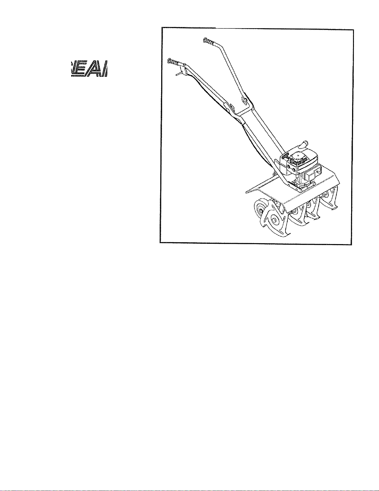
32.8 cc 2-CYCLE
10 INCH DIAMETER TINES
MINI TILLER/CULTIVATOR
® Assembly
® Operation
® Customer Responsibilities
® Service and Adjustments
® Repair Parts
Ri
SEARS, ROEBUCK AND CO., Hoffman Estates 60179 U.S.A.
Page 2

SAFETY RULES
CAUTION; ALWAYS DISCONNECT SPARK PLUG WIRE AND PLACE WIRE WHERE
IT CANNOT CONTACT SPARK PLUG TO PREVENT ACCIDENTAL STARTING
4
WHEN SETTING-UP, TRANSPORTING, ADJUSTING OR MAKING REPAIRS
IMPORTANT
CACcpy qjaIsidaRDS REQUIRE OPERATOR PRESENCE CONTROLS TO MINIMIZE THE RISK OF INJURY YOUR
MINITILLER/CULTIVATOR IS EQUIPPED WITH SUCH CONTROLS DO NOT ATTEMPTTO DEFEATTHE FUNCTION
QP THE OPERATOR PRESENCE CONTROL UNDER ANY CIRCUMSTANCES.
BEFORE USE
® Read the owner’s manual carefully. Be thoroughly farnil*
iar with the controls and the proper use of the mini tiller/
cullivalot. Know how to stop the mini liller/cuitivator and
disengage the confrois quickly.
® Do not operate the mini iiller/cultivator without wearing
adequate outer garments. Wear footwear that will im
prove footing on slippery surfaces
® Keep the area of operation clear of all persons, parlicu-
larly small children and pets.
# Thoroughly inspect the area where the mini tiller/cultiva-
tot is to be used and remove all foreign objects
FUEL SAFETY
® Handle fuel with care; it is highly flammable
# Use an approved container
® Check fuel supply before each use, allowing space for
expansion as the heat of the engine and/or sun can
cause fuel to expand
# Fill fuel tank outdoors with extreme care. Never fill fuel
tank indoors Replace fuel tank cap securely and wipe up
spilled fuel
® Never remove the fuel tank cap or add fuel to a running
or hot engine
@ Never store fuei or mini tiller/cultlvator with fuel in the
tank inside a building where fumes may reach an open
flame,.
OPERATING SAFETY
® Never allow children or young teenagers to operate the
mini tiller/cuitivator Keep them away while it is operat
ing. Never allow adults to operate the mini tliler/cultivator
without proper instruction,
# Always wear safety glasses or eye shields during opera
tion or while performing an adjustment or repair to
protect your eyes from foreign objects that may be
thrown from the mini iillef/cultivator
® Do not put hands or feet near or under rotating parts,
® Exercise extreme caution when operating on or crossing
gravel drives, walks, or roads Stay alert for hidden
hazards or traffic.
® Exercise caution to avoid slipping or falling
® Never operate the mini iiller/cultivator without proper
guards, plates, or other safety protective devices in
place.
® Never operate the mini tiller/cuitivator at high transport
speeds on slippery surfaces Look behind and use care
when backing
® Never aliow bystanders near the mini tiller/cuitivator
® Keep children and pets away white operating
® Never operate the mini tiiler/cuitivalor without good
visibility or light
® Do not run the engine indoors. The exhaust fumes are
dangerous (containing CARBON MONOXIDE, an
ODORLESS and DEADLY GAS)
9 Take al I poss ib!e precau tlo ns when lea ving th e m in i til le r/
cultivator unattended - Stop the engine
® Do not overload the mini tiller/cuitivator capacity by
attempting to till too deep at too fast a rate
SAFE STORAGE
® Always refer to the owner's manual instructions for
important details if the minitiiler/cultivator is to be stored
for an extended period
® Never store the mirii tiiier/cultivalor with fuel in the fuel
tank inside a building where ignition sources ate present
such as water and space heaters, clothes dryers, and
the like Aliow the engine to cool before storing in any
enclosure
# Keep the mini tiller/cuitivator in safe working condition
Check ali fasteners at frequent intervals for proper
tightness
REFAiR/AOJUSTMENTS SAFETY
# After striking a foreign object, stop the engine (motor)
Remove the wire from the spark plug, and keep the wire
away from the plug to prevent accidental starting Thor
oughly inspect the mini iiller/cultivator for any damage,
and repair the damage before restarting and operating
the mini tiller/cuitivaior
@ If the mini tiller/cuitivator should start to vibrate abnor
mally, stop thesngirie (motor) and check immediately for
the cause Vibration is generally a warrting of trouble,
® Stop the engine (motor) whenever you leave the operat
ing position. Also, disconnect the spark plug wire before
uriclogglng the tines and when making any repairs,
adjustments, or inspections,
@ When cleaning, repairing, or inspecting, shutoff the
engine and make certain ail moving parts have slopped,
® Never attempt to make any adjustments while the en
gine is running (except when specifically recommended
by the manufacturer)
/4.1
LOOK FOR THIS SY!
ATTENTION!l! BECO]
mOL TO POINT OUT IMPORTANT SAFETY PRECAUTIONS. iT MEANS№ ALERT!!! YOUR SAFETY IS INVOLVED.
Page 3

CONGRATULATIONS on your purchase of a Sears
Craftsman Mini tiller/culfivalor It has been designed,
engineered and manufactured to give you the best pos
sible dependability and performance
Should you experience any problem you cannot easily
remedy, please contact your nearest Sears Service
Center/Department. We have competent, welt-trained
technicians and the proper tools to service or repair this
unit
Please read and retain this manual. The instructions wHi
enable you to assemble and maintain your mini tiller/
cultivator properly. Always observe the "SAFETY
RULES."
MODEL
NUMBER 536 797500
DATE
CODE
DATE OF
PURCHASE
THE MODEL AND DATE CODE WILL BE FOUND
ON A DECAL ON THESIDEOFTHE MINITILLER/
CULTIVATOR TINE SHIELD
YOU SHOULDRECORD BOTH DATE CODE AND
DATE OF PURCHASE AND KEEP IN A SAFE
PLACE FOR FUTURE REFERENCE
MAINTENANCE AGREEMENT
A Sears Maintenance Agreement is available on this
product. Contact your nearest Sears Store for details
CUSTOMER RESPONSIBILITIES
® Read and observe the safety rules
• Follow a regular schedule in maintaining, caring for
and using your mini tilier/cultfvator
® Foiiow the instructions under "Customer Responsi-
bi!ities"and "Storage” sections ot this owner’s manual
PRODUCT SPECIFICATIONS
HORSE POWER;
DISPLACEMENT:
GASOLINE CAPACITY:
FUEL/OIL MIX RATIO:
SPARK PLUG :
(GAP .035 in.)
WARNING: This unit is equipped with an internal com
bustion engine and should not be used on or near any
unimproved forest-covered, brush-covered or grass-cov
ered land unless the engine’s exhaust system is equipped
with a spark arrester meeting applicable local or state
laws (if any) if a spark arrester is used, it should be
maintained in effective working order by the operator
in the state of California the above is required by law
(Section 4442 of the Caiifornia Public Resources Code)
Other stales may have similar laws Federal laws apply
on federal lands A spark arrester/muffler is available
through your nearest Sears Authorized Service Center
(See REPAIR p/s,Rj3 section in this manual)
1.6 hp
2.0 cu. in.
(32.8 C.C)
16 oz.
Unleaded
(Regular)
24:1 Gas To Oil
(5 Oz. Oil/1 Gal.
Gas)
Champion
CJ'8Y
LIMITED ONE-YEAR WARRANTY ON CRAFTSMAN
MINI TILLER/CULTIVATOR
For one year from the date of purchase, when this Craftsman Mini tiller/cuilivator is maintained, lubricated, and
tuned up according to the operating and maintenance instructions in the owner's manual, Sears will repair, free
of charge, any defect in materia! or workmanship '
This warranty excludes tine(s), spark piug, and air cleaner which are expendable parts and become worn
during normal use
If this Mini tilier/cuitivator is used for commercial or rental purposes, this warranty applies lor only 30 days from
the date of purchase This warranty applies only while this product is in use the United States WARRANTY
SERVICE IS AVAILABLE BY RETURNING THE MINI TILLER/CULTIVATOR TO THE NEAREST SEARS
SERVICE CENTER IN THE UNITED STATES
This warranty gives you specific legal rights, and you may also have other rights which vary from state to state
SEARS, ROEBUCK AND CO.,D817WA, Hoffman Estates, IL 60179 USA
Page 4

TABLE OF
rONTFNTS
1 a— a ^ 1
SAFETY RULES
PRODUCT SPECIFICATIONS...,,,.
...
................................
.............
CUSTOMER RESPONSIBILITIES....3,
WARRANTY.....................
TABLE OF CONTENTS
...........................
.................. ...
CONTENTS OF SHIPPING CARTON
OPERATION......
Adjustments:
Carburetor
Assembly..
Tools Requited..............
To Assemble
Carburetor Adjustment
Choke Corttrol ...............
Check List:
Operation
Maintenance
Cleaning
Controls, Mini tiller/cullivator ,9,10
Guttivafing Hints.,
Customer Responsibilities .3,13-15
General Recommendations
Lubrication.....................
Mini tiiler/cultivator
Air Cleaner, Engine
Cylinder Exhaust Potts ..
Spark Plugs
.........................
........................
...................................
A
.
.....
......
.
.
..,6-8
,13
13,14
.
....
„,.17
.6-8
.....
..,,17
,9,11
.....
,.,.15
,, .12
,,.,13
.,..13
,14
14
,14
6
8
...........................
.......................
G
..........
...........................
....
....................................................
....... .........
.........
.........
..........
........
Fuel:
General Recommendations
Hand Grip
Lubrication:
Operation
Operating
Your Mini tiller/cuitivator
Options
.
.......
.......
2
3
.
13-15
........3
........
.
¿j,
....
6-8
,.,9-12
INDEX
Type
.... ..........................
Storage
Assembly
Spark Arrestof
.........
.......
Mini tiiler/cultivator
Engine
..........................
...........................
SERVICE AND ADJUSTMENTS.
STORAGE...........
............................
TROUBLE SHOOTING.....................
REPAIR PARTS
{MIN! TILLER/CULTIVATOR)
REPAIR PARTS (ENGINE)
PARTS ORDERING/SERVICE
F
Safety Ruies
, 11 Service and Adjustments
.............
...................
,,
G
H
L
.......
0
......
................
. ,17
13
.... 8
,13 Tilling Hints...................
.
.. 11
9-12
.....
10
.......
3
.
Carburetor
Specifications
Starting the Engine
Stopping the Mini tiller/cuitivator 10
Storage
Table of Contents
Throttle Control
Tines
Troubleshooting Points .
Warranty
............................
Assembly
Operation
Replacement
..........
..............
........
......... ......
.................
....................
T
............
......................
..............
W
..........
...........16-17
................
................
...........
...........
.Back Cover
s
.........
, 16-17
...........
............
. 11
......
,, . 19
18
19
20-25
26-29
2
, 3
17
4
8
.9
12
, , 16
2
Engine:
Air Cleaner
Gas and Oil Mixture
Preparation
Starting
Storage
.........................
........................
...............................
............................
E
............
....
14
11
10,11
....
11
...
17
P
Parts Bag
Product Specifications
............................
R
Repair Parts:
Mini tiller/cuitivator
Engine.........................
.....
....
5
,.3
20-25
26-29
.
Page 5
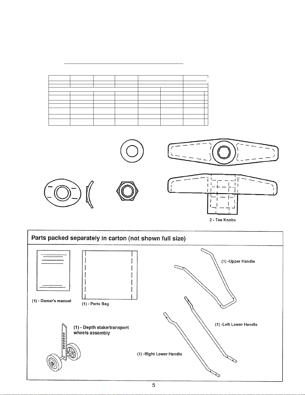
CONTENTS OF HABDWARE PACK
CONTENTS OF PARTS BAG (shown actual size)
iiiMiiiii HiiMiHiiuiMmiimuniUiinuuimiui
===@
;
........
f
' ■
. -
big~'~
_____
............
:../
n -
_
b=d
..........
f
VlllliJ
^ 2 - Curved Head Screws
2 - Formed {Curved) Washers
1 - Tie Strap
^
---------
J
T:
-1
_
____
-
----------
..
_
*
2»Hand Grips
2 -11/32 inch Ffatwashers
2-S/16'1BHexNwis
....
1
}
J
.
..............I_
gjiiSSiSI
^
................
SKsSiSSlb
z>
..
'i
[ImOTiTO»
^ 1-10-iex 1-1/2 inch
Washer Head Tap Screw
Page 6
AQQPiiRI Y
CAUTION; ALWAYS WEAR SAFETY
GLASSES OR EYE SHIELDS WHILE
A
TOOLS REQUIRED FOR ASSEMBLY
1-5/16 inch Wrench {or adjustable wrench)
2 - 7/16 inch Wrenches (or adjustable wrenches)
1 ' Regular Screwdriver
1 - Pair Scissors
1 ' Hammer
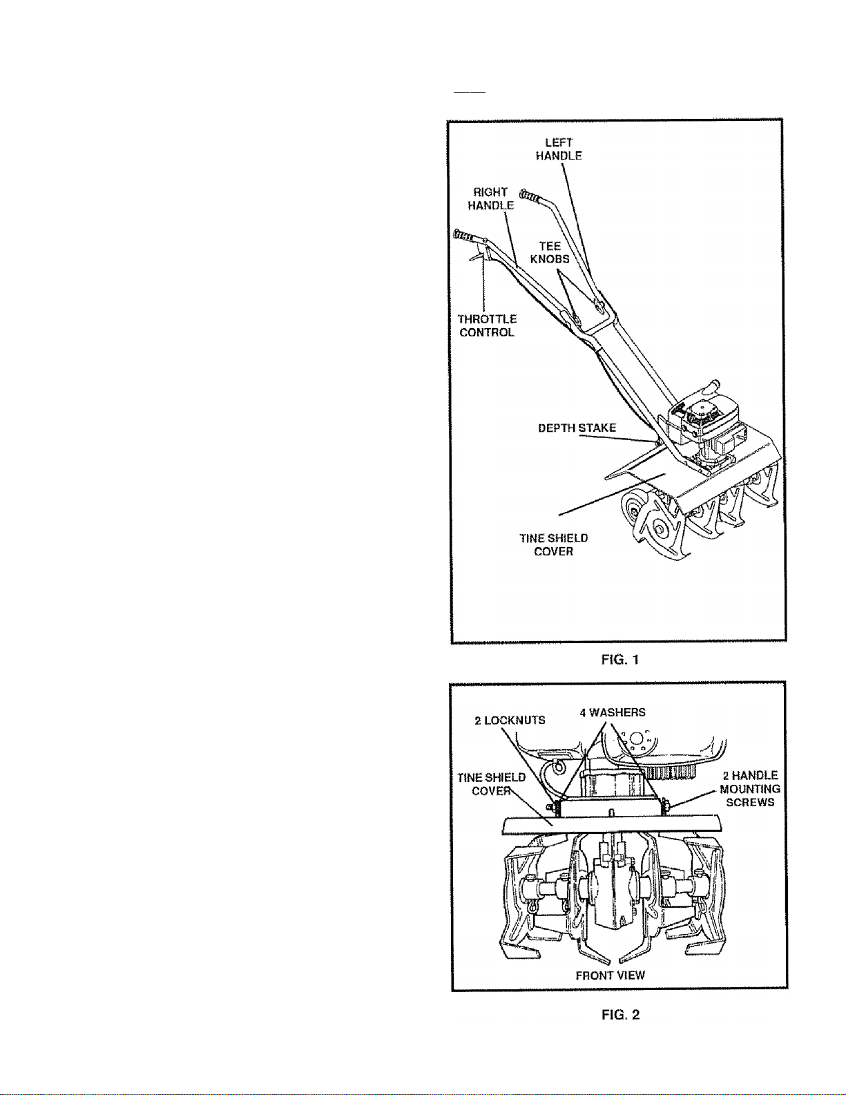
Figure 1 shows the mini tiller/cultivator completely
assembled
Reference to the right and let! hand side of the mini tiller/
cultivator is from the operator’s position behind the unit
TO REMOVE MINI TILLER/CULTIVA
TOR FROM CARTON
# Remove the piastic parts bag from the carton
® Remove the handles 1rom the carton
® Remove packing insert trom carton that contains
depth stake/transport wheels assembly
® Lift the tiller/mini tiller/cultivator out of the carton and
place on a hard level surface
® Remove packing material from around tines
ASSEMBLING TILLER/ MINI TILLER/
CULTIVATOR.
|L-, pMi d i— I
TO INSTALL THE HANDLE ASSEMBLY
The lower handles have a short bend at the bottom end
arid are flattened at the top to allow the upper handle to
be placed between the lower handles To assemble the
handles, do the following:
® Unwind the throttle control from around the engine
and straighten the cable Be careful you do not kink
the cable.
® Remove two iocknuts, four washers and two handle
mounting screws from the tine shield (see Fig 2)
Page 7

ASSEMBLY
® Insert the right side lower handle section info the
mouniirig channel between the tine shield and the
engine casting {see Fig 3) Push the mounting
screws through the tine shield. handle and approxi
mately haft way into the engine casting Be sure a
washer is on each mounting screw (see Fig 4) It
may be necessary to rotate the lower handle to align
the mounting holes. To allow proper mounting of the
upper handle section be sure the flat portion of the
lower handle is facing inward
@ Position the left side lower handle section info the
mounting channel between the tine shield and the
engine casting Align the holes in the handle with the
engine casting and the tine shield, then push the
mounting screws completely through the engine
casting, handle and tine shield install a washer onto
the mounting screws and secure the lower handle
sections using two locknuts previously removed (see
Fig 4). Finger tighten the locknuts at this lime
® Place the upper handle between the lower handies
(see Fig. 5) and secure with two curved head car
riage bolts, two formed washers, two 11/32 inch
fiatwashers and two tee knobs on the inside of the
handle You must insert a hex nut Into each tee
knob. Finger tighten only Pul! back on the tee knob
to engage the hex opening with the hex nut Tighten
the tee knob. The nut will be pulled into the cavity and
locked. The lower handles have two holes at the top
end to allow the upper handle to be positioned at two
different heights,
# Using two 7/16 inch wrenches, tighten the locknuts
on the screws in the lower ends of the lower handles
just enough to hold the lower handles firmly in place
IMPORTANT: OVERTIGHTENING THE SCREWS
ENOUGH TO CHANGE THE SHAPE
OF THE HANDLES CAN RESULT IN
DAMAGE TO THE ENGINE CASTING
@ Hold the curved head carriage boll against the out
side of the lower handle while tightening the tee
knobs securely (see Fig 5)
Page 8

ASSEMBLY
TO INSTALL THE THROTTLE CONTROL ASSEMBLY
@ Place a No 10 x 1-1/2 inch hex head screw down
through the hole in the upper handle right side and
attach the throttle control to the underside of the handle
(see Fig, S),
m Attach the throttle cable to the right lower handle by
threading a tie strap through the hole in the lower
handle and around the throttle cable on the outside o1
the handle.
# Thread the pointed end of the strap through the other
(square) end of the strap and pull tight around the
throttle cable and lower handle.
NOTE: One side of the tie strap is rough, while the other
side is smooth The rough side must be on the inside of the
loop formed when the ends of the tie strap are put together,
® Try to loosen the tie strap, if it will loosen, it is put
together with the smooth side to the inside of the loop
Remove the tie strap and reverse the direction
® Cut off excess strap
HANDGRIP ASSEMBLY
# Install the hand grips onto the upper handies (see Fig
5). It may be necessary to lubricate the handles with
soap and water to aid assembly
Cui* fy. imi' W
BEFORE YOU OPERATE AND ENJOY YOUR NEW
MINI TILLER/CULTIVATOR, WE WISH TO ASSURE THAT
YOU RECEIVE THE BEST PERFORMANCE AND SATISFAC^
riON FROM THIS QUALITY PRODUCT
PLEASE REVIEW THE FOLLOWING CHECKLIST.
/ All assembly instrudions have been completed
/ Ha remaining loose parts in carton.
/ All fasteners have been properly installed and tightened
WHILE LEARNING HOW TO USE YOUR MINI TILLER/CUL TiVATOR. PAY EXTRA ATTENTION TO THE FOLLOWING
IMPORTANT ITEMS:
// Fuel tank is filled with correct gasoiine and oil mixture
// Become familiar with all controis-their location and
function, operate controls before starting engine,
Page 9

OPERMIOW
KNOW YOUR MINI TILLER/CULTIVATOR
READ THIS OWNER’S MANUAL AND SAFETY RULES BEFORE OPERATING YOUR MINI
TILLER/CULTIVATOR Compare the illustrations with your mini tiller/cultivalor to familiarize yourself with the
location of various controls and adjustmenfs Save this manual for future reference
SEARS MINI TiLLER/CULTiVATOR conforms to the safety standards of the
American National Standards Institute B71 8
THROTTLE CONTROL - Controls the engine speed and
the tine rotafion. This mini tiiler/cuitivatoris equipped with
a centrifugai dutch that engages the tine drive system
when the engine speed is increased
CHOKE CONTROL LEVER - Used to assist in sfarting a
co!d engine,
SHUT-OFF SWITCH ^ Used to stop the engine
RECOIL STARTER HANDLE - The engine on this mini
tiller/cultivatoris equipped with an easy pull recoil starter
DEPTH STAKE/TRANSPORT WHEELS ASSEMBLYUsed (with wheels up) when tilling or cultivating to adjust
the depth of the cut it also acts as a brake to help the
operator control the direction and speed of the unit
The depth stake/transport wheel assembly (with wheels
down) can be used for transporting the unit
Page 10

©PERÄTiOM
The operation of this mini liller/cullivator can result in foreign objects being thrown
into the eyes, which can result in severe eye damage Always wear safety glasses
or eye shields while operating the mini tiller/cuitivator,
We recommend standard safety glasses or Wide Vision Safety Mask for over your
glasses.
TO STOP MINI TILLER/CULTIVATOR
® Release the throttle control to stop the tines
® Move the shuboff switch on the engine to the "OFF"
position
TO OPERATE
MINI TILLER/CULTIVATOR
® Set the depth stake/transporl wheels assembly to the
desired tilling position as follows:
# Remove the hairpin cotter t ro m the cievi spin securing
'the depth slake (see Figure 8} Remove the clevis pin
and adjust the depth stake upward to dig shallower or
downward to dig deeper Reinstall the clevis pin and
hairpin cotter
# Start the engine, tilt the unit back on the depth stake
untli the tines are off the ground and squeeze ihe
throttle control all the way up against the hand grip
The engine is governor controlled and should be run
at full throttle
® Gras p the h a ndtes fir ml y and slowly till 1 he u nit to rward
to begin the lilting action
@ As the tines begin to make contact with the ground,
hold back on the handles so that the tines will dig and
not ride forward over the ground Hold back until the
tines dig into the soil
© If the tilled depth is too deep ortoo shallow, turn off the
engine and reset the depth stake
# If depthstake is not controiling forward action, lower
the depth stake If the unit is not going forward, raise
the depth stake
CAUTION: GASOLINE IS FLAMMABLE
AND CAUTION MUST BE USED WHEN
ä
FILL FUEL TANK WHILE MINI TILLER/CULTIV ATOR IS RUNNING, HOT, OR WHEN MINI TILLER/
CULTIVATOR IS IN AN ENCLOSED AREA. KEEP
AWAY FROM OPEN FLAME, ELECTRICAL
SPARK, AND DO NOT SMOKE WHILE MIXING
FUEL OR FILLING THE FUEL TANK. NEVER
FILL FUEL TANK COMPLETELY; BUT FILL THE
TANK TO WITHIN 1 /4 -1/2 INCH FROM THE TOP
TO PROVIDE SPACE FOR EXPANSION OF FUEL.
ALWAYS FILL FUEL TANK OUTDOORS AND
USE A FUNNEL OR SPOUTTO PREVENT SPILL
ING. MAKE SURE TO WIPE UP ANY SPILLED
FUEL BEFORE STARTING THE ENGINE.
STORE GASOLINE IN A CLEAN, APPROVED
CONTAINER, AND KEEP THE CAP IN PLACE ON
THE CONTAINER. KEEP GASOLINE IN A COOL,
WELL VENTILATED PLACE; NEVER IN THE
HOUSE. NEVER BUY MORE THAN A 30 DAY
SUPPLY OF GASOLINE TO ASSURE VOLATIL
ITY. GASOLINE IS INTENDED TO BE USED AS A
FUEL FOR INTERNAL COMBUSTION ENGINES;
THEREFORE, DO NOT USE GASOLINE FOR
ANY OTHER PURPOSE. SINCE MANY CHIL
DREN LIKE THE SMELL OF GASOLINE, KEEP IT
OUT OF THEIR REACH BECAUSE THE FUMES
ARE DANGEROUS TO INHALE, AS WELL AS
BEING EXPLOSIVE.
HANDLING OR STORING IT. DO NOT
BEFORE STARTING ENGINE
A
CAUTION: KEEP AWAY FROM THE RO
TATING TINES. ROTATING TINES CAN
CAUSE INJURY.
FILL GAS
The two cycle errgine used on this mini tiller/cuitivator
requires a mixture of gasoline and oil for lubrication of the
bearings and other moving parts The correct fuel mixture
ratio is 24:1 (see Fuel Mixture Chart) Gasoline and oil
must be premixed in a clean gasoline container Always
use fresh, clean unleaded gasoline
WARNING: Experience indicates that alcohol blended
fuels (called gasahol or using ethanol or methanol) can
attract moisture which leads to separation and formation
of acids during storage Acidic gas can damage the fuel
system of an engine white in storage To avoid engine
problems, the fuel system should be emptied before
storage for 30 days or longer. Drain the gas tank, start
10
Page 11

OPERATION
the engine and iet it run until the fuel lines and carburetor
are empty Use fresh fuel next season See Storage
Instructions for additional information. Never use en
gine or carburetor cleaner products In the fuel tank or
permanent damage may occur
GASOLINE AND OIL MIXTURE
Mix gasoline and oil (See Fig 7) as follows;
® Pour 1 U S quart of fresh, clean, unleaded automo
tive gasoline into a gallon gasoline container.
® Add (5 oz,) of clean, high quality SAE 30 or SAE 40
two-cycle oil into the gasoline container
ÍMPORTANT: DO NOT USE OUTBOARD MOTOR
OIL OR MULTI-VISCOSITY OILS,
SUCH AS 10W-30 OR 10W-40.
® Reinstall the cap on the gasoline container and shake
container vigorously so the oil mixes with the gasoline
® Add an additional 3 Li S quarts of gasoline to the
gallon container and shake the container again
FUEL MIXTURE CHART (Mixture 24:1)
u. s.
GAS
1 Gal.
2 Gal. 11 oz.
5 Gal. 27 01.
otu
EÜPOní 031}
..
"•*.*"
j'fryflTTIWtlii
1 E1.S, CJUXOK
® This completes the special gasoline mixing (24:1)
procedure. It can now be poured into the mini tiller/
cultivator fuel tank
IMPORTANT: DO NOT FILL FUEL TANK WITH
OIL
5 oz.
Jl
GASO- LINE THAT DOES NOT HAVE
OIL MIXED IN IT DO NOT USE GASO
LINE ADDITIVES BECAUSE THE EN
GINE MAY BE DAMAGED SHAKETHE
GASOLINE CONTAINER BEFORE
EACH FILLING OF THE FUEL TANK
S. 1. (METRIC)
GAS OIL
4 Liters .167 L
8 Liters .333 L
20 Liters .833 L
■
FIG. 7
TO START THE ENGINE
Before starting the engine, be sure you have read and
understood all the instructions on the preceding pages
® Fill the fuel tank (to 1/2 inch below the bottom of the fill
neck) with fresh fuel mix and reinstall the fuel lank cap
securely Never use fuel that may be stale from long
periods of storage
@ Move the shut-oft switch to the ON position
® Move the choke controi (see Fig 6) to the FULL choke
position (ail the way down)
NOTE: A warm engine should not require choking
CAUTION: DO NOT TOUCH THE
THROTTLE CONTROL WHILE START
ING THE ENGINE. THE MINI TILLER/
CULTIVATOR WILL PROPEL ITSELF IF
THE ENGINE SPEED IS ADVANCED
FROM IDLE.
@ Tilt the mini tiller/cuilivator back on the depth stake or
transport wheels to raise the tines off the ground
@ Grasp the upper handle firmly lo stabilize the mini
tiiler/cultivator and pull the starter handle with short
quick puiis Do not allow the starter handle to snap
back, let it rewind slowly while holding the starter rope
It will take a few pulls on the starter handle to leed gas
from the fuel tank to the carburetor
@ When engine starts, move the choke control to 1/2
choke position until the engine runs smoothly Then
move choke control to OFF position
® If engine taiters, move choke control to 1/2 choke
position until engine runs smoothly Then move
choke control to OFF position
® If engine fires, but does not continue to run, move
choke control to no choke position and repeat starting
instructions
NOTE: If the tines do not stop when the throttle control is
released, adjust the carburetor Idle speed as instructed in
Step 5 ot Carburetor Adjustment paragraph in the
ServIce/Adjustments section ot this manual
® To stop the engine, release the throttle control and
move the shut-off switch to the OFF position
® If the engine becomes flooded, see the Spark Plug
Maintenance paragraph in the Maintenance section
of this manual Then pull the starter rope with the
choke "OFF"
CAUTION: THE MUFFLER AND SUR
ROUNDING AREAS BECOME HOT AF
A
TER RUNNING THE ENGINE, AVOID
THESE AREAS,
11
Page 12

OPERATION
TILLING HINTS
® Tilling is digging in, turning over and breaking up
packed soil before planting. Loose unpacked soil
helps root growth Best tilling depth is 4 to 6 inches, A
tiller will also clear the soil of unwanted vegetation.
The decomposition of this vegetation matter enriches
the soil. Depending on the climate (rainfall and wind),
it may be advisable to til! the soil at the end of the
growing season to turfher condition the soil,
® Avoid 1iHing t he soil f hat is too dry as the soil puIverizes
and produces a dust that will not hold water Also,
tilling soil that is too wet will produce unsatisfactory
clods besides being hard on the machine.
® Better growth will be obtained in tilled ground if a
relatively small area is tilled properly and the tilled
ground used soon aftertillingto preserve the moisture
content,
® The depth stake (on the back of the mini tiller/
cultivator)serves actual purpose (see Fig 8) It helps
regulate the depth of the cut to a uniform level and also
acts as a brake to help the operator control the speed
oiihe mini tiller/cultivator.
9 Lowering the depth stake will slow the mini tiller/
cultivator and make it till deeper Raising the depth bar
will allow the mini tiiler/cultivator to move faster and till
more shallow.
® if the tiller mini tiiler/cultivator stops forward motion
and fries to dig deeper than necessary, move the
handles from side to side to start forward motion
CULTIVATING HINTS
9 When cultivating (weed killing) il is best to till no
deeper than 1 -1 /2 inches Tilling deeper will oniy pull
to the surface ungerminated weed seeds You may
want to raise the depth bar to lessen the braking
action
® When cultivating around plants or dose areas you
may want to remove the outside tines (see Tine
Reptacemetit parag r aph in the Service/Adjustments
section of this manual)
12
Page 13

CUSTOMIE3 RESPONSIBILITIES
SERVICE RECORDS
SCHEDULE
Fill in dates as you compiGte reguiar service
Tighten All Screws and Nuts
Lubricate Transmission
Lubricate Tine Shaft
Clean and Re-Oil Air Cleaner Fitter
Check Spark Plug
Cylinder Exhaust Ports
Drain Fuel
Before After
Each
Use Hours
first 2
Every
25
Hours
GENERAL RECOMMENDATIONS
The warranty on this mini liller/cultivator does not cover
items that have been subjected to operator abuse or
negiigence To receive full value from the warranty, the
operator must maintain the mini tiiler/cuitivator as in
structed in this manual. The following Service Recom
mendations Chart is provided to assist the operator in
properly maintaining the mini tiiler/cuitivator
SERVICE DATES
Every
Before
75
Storage
Hours Season
# Check the condition of the felt washer in the side of Ihe
AIR VENT SCREW
Before
Each
transmissionatihelineshaU(seeF(g 9) Replace Ihe
felt washer if it is damaged (see Repair Parts section
in this manuail
TRANSMISSION
FELT WASHER
LUBRICATION
Every 25 hours and/or at the beginning of each season,
thegearboxshouldbefifiedwithfubhcani- Tubesofgear
lubricant are available from most automotive supply
stores Use portable tool grease such as Lubriplate
630AA (Product No 06787-1-3/4oz tube) orLubriplaie
GR-132 (Product No 15892-10 oz tube). The tine shaft
should have oil applied before storage and after clean
ing, if the mini tiiler/cuitivator is flushed with water The
fofiowing illustration is provided to assist the operator in
properly maintaining the mini tilier/cultivator
CAUTION: ALLOW THE TRANSMISSION
TO COOL BEFORE FILLING WITH
GREASE,
® Remove both left side tines (see Adjustments/ Re
pairs section) in this manual.
@ Remove the airvent screw (see Fig 9)fromthetopleft
side of the fransmission
® Using a grease gun, fill the transmission through the
grease filling until the new grease begins to come out
of the air vent screw hole
® Reinstall the air vent screw.
TINE SHAFT
Oil the tine
shaft before
storage and
after
cleaning, If
the mini tiller/
cultlsialor is
GREASE
FITTING
(Lubricate the
gear box with
lubriplate
03OAA or
Lubriplate
GR-132
VIEW OF LEFT SIDE WITH TINES REMOVED
flushed with
aterj
FIG. 9
Clean tine shaft, spread a few drops of oil on shaft in
line replacement areas Reinslall the tines
Remove the right side tines Check the felt washer for
damage, clean and oil the tine shaft Reinstall the
tines.
13
Page 14

CUSTOR/IER RESPONSIBILITIES
ENGINE
AIR CLEANER MAINTENANCE
The air cteaner filter should be cleaned and reoiled atter
every 25 hours of use Clean more often under dusty
conditions
IMPORTANT: THE ENGINE CAN BE WORN OUT IN
A VERY SHORT PERIOD OF TIME IF
DIRT OR GRIT IS ALLOWED TO EN
TER THE ENGINE,,
To clean the air filter, do the following:
# Loosen screws on air cleaner cover (see Fig 10) and
remove the cover.
® Remove foam element from air cleaner
® Wipe inside of the air cteaner housing clean
® Glean the foam element by washing in a strong
solution of water and household detergent. Then
rinse thoroughly in clean water.
® Wrap foam element in clean cloth and squeeze out
(do not twist) all the liquid until dry.
# Cover the ends and side of the foam element with
same oil used in fuel mixture Knead the foam
element between fingers to distribute oil and remove
excess oil
® Reinstall foam element in air cleaner housing.
® Service the foam element carefully, inspection for
deterioration or damage A defective, improperly
sen/iced, or misassembled air filter will allow dirt
particies to enter the engine.
® Reassemble the filter (see Fig 10) Place the cover
on the air cleaner housing and tighten screws to
secure cover to the housing.
SPARK PLUG MAINTENANCE
if the engine is flooded, clean the area around the spark
plug base to prevent foreign material from entering the
cylinders when the plug is removed Remove and dry the
spark plug Regap the electrodes to 035 if necessary If
a new spark plug is needed, refer to the Engine Opera
tion and Maintenance manual lor the proper replace
ment sparkplug Tighten the spark plug firmly if a torque
wrench is available, torque the spark plug to 15 foot
pounds
CYLINDER EXHAUST PORTS
The cylinder exhaust ports should be cleaned after each
seventy-five (75) to one hundred (100) hours of opera
tion For this procedure we recommend that you take
your unit to a technician trained to work on two cycle
engines, such as a SEARS Service Center
A
CAUTION: NEVER RUN THE ENGINE
WITHOUTTHE AIR CLEANER ELEMENT
INSTALLED. A DEFECTIVE AIR
CLEANER CAN RESULT IN LOSS OF
ENGINE POWER AND CAN CAUSE EX
CESSiVE WEAR OR DAMAGE TO THE
ENGINE COMPONENTS IF DIRT OR
DUST IS PERMITTED TO ENTER THE
ENGINETHROUGH THE CARBURETOR.
AN AIR CLEANER THAT IS CLOGGED
WITH DUST OR DIRT SHOULD BE
CLEANED AND RE-OILED.
14
Page 15

eiJg l?£FONSIBiUTIES
CLEANING
Always remove the dirt and debris from the mini tiller/
cultivator after each use (see Fig, 11) Remove atiy
string, wire or vegetation that may become lodged in the
mechanism and stop the tine rotation Proceed as fol
lows;
® Release the throttle control and move the shut-off
switch to the OFF position, then disconnect the spark
plug wire
® Remove the hairpin and clevis pin securing the tine(s)
assemb ly to I he shaft and re move the tine (s) (see Fig
11).
# Remove the lodged material. Reassemble the tine(s)
on the shaft and secure with a clevis pin and hairpin
@ Reconnect the sparkplug wire and restart the engine
FRONT VIEW
TINE SHIELD
LOOGED ITEM
CLEVIS PINS
RIGHT SIDE ‘
TINES
HAIRPINS
TRANSMISSION
FIG. 11
LEFT SIDE
TINES
HAIRPINS
15
Page 16

SE™CE AMD ADJUSTIIEMTS
TINE REPLACEMENT
The mini tilier/cultivator is ieft hand or right hand as
viewed from the operator's position behind the unit
All four tines on this unit are different and cannot be
interchanged The tines must be properly installed as
shown in figures 12 and 13 or the mint tilier/cultivator will
not function property
The outside tines may be removed to reduce the tilling
width to about 7 inches, for working close around plants
orinsmall areas, if desired. When reinstaiiing the outside
tines see below.
CAUTION: THE TINES ARE SELFSHARPENING AND WILL BECOME
A
The lines will all wear fairly eveniy. If the tines are being
replaced because of wear, we recommend that ai! four
tines be replaced at the same time To replace the tines,
do the following:
# Place the shut-off switch to the OFF position and
@ Removethehairpinsandthedevispinslromthetines
9 Clean the tine shaft and oil the shaft at the tine
® Piace the inside tine on the tine shaft and reinstall the
® Whenthe tines are properly installed, the letter "R" will
• Place the outside tine on the tine shaft and reinstall f tie
® The outside tine cutting tips wiil all bend in toward the
® Repeat steps on the opposite side of the unit
® Check to make sure the tines are installed on correct
QUITE SHARP FROM USE. HANDLE
CAREFULLY.
disconnect the spark plug wire
on one side of the unit and remove the fines.
locations.
clevis pin and hairpin,
be visible on the outside of the right-hand tine (the
letter "L" on the left-hand tine). The letter should
appear opposite the small hole in the side of the tine
clevis pin and hairpin cotter,
inside line The letter"R‘'onthe right sideorT“on the
left side should be visible from the outside of the unit,
side of the unit
RIGHT SIDE
TINES
FRONT VIEW
• 1 i'!
Í i iLi
CLEVtg PINS
HAIRPINS
FIG. 12
ilillffHf
I LEFT SIDE
TINES
16
Page 17

SERVICE AMD ADJUSTMEWTS
CARBURETOR ADJUSTMENT
A dirty air cleaner will cause the engine to run
improperiy and/or smoke excessively. Be sure the
air cleaner is clean before adjusting the carburetor.
Never make unnecessary adjustments to the carburetor
The carburetor was set at the factory to operate efficiently
under most applications However, if adjustments are
required, we recommend you contact your nearest SEARS
Service Center If you feel that you are competent to
make carburetor adjustment proceed as foiiows:
CAUTIDNiUSEEXTREIViECAREWHEN
MAKING ADJUSTMENTS THAT RE
A
® Turn the mixture adjustment screw {see Fig 14)
clockwise to close
IMPORTANT: TIGHTEN THE ADJUSTING SCREW
# Turn the mixture screw counterclockwise (open) one
(1) turn,
® Start the engine and let it warm up approximately 3 to
5 minutes Do not adjust the carburetor when the
engine is cold
® if the engine falters or stops after the choke lever is
moved to the OFF position, open the mixture adjusting
screw an additional 1/8 turn counterclockwise
# With the engine running, release the throttle control
(idle position) to make the mixture adjustments
a. Turn the mixture adjusting screw (see Fig, 14)
b. Turn the mixture adjusting screw slowly counter
c. Turn the mixture adjusting screw clockwise until
QUIRE THE ENGINE TO BE RUNNING,
KEEP HANDS, FEET, HAIR AND LOOSE
CLOTHING AWAY FROM ANY MOVING
PART.
WITH YOUR FINGERS TO PREVENT
DAMAGE TO THE CARBURETOR OR
ADJUSTING SCREW.
slowly clockwise until the engine falters Note this
location.
clockwise until the engine starts to sputter Note
this location
it is halfway between the first position where the
engine faltered and the second position where
the engine started to sputter
-fl il ^ '
IDLE SPEED
ADJUSTING
SCREW
ENGINE SHOWN WITH AIR CLEANER REMOVED
CAUTION: NEVER TAMPER WITH THE
ENGINE GOVERNOR WHICH IS FAC
TORY SET FOR PROPER ENGINE
SPEED. OVER-SPEEDING THE ENGINE
ABOVE THE FACTORY HIGH SPEED
SETTING CAN BE DANGEROUS. IF YOU
THINK THE ENGINE GOVERNED HIGH
SPEEDS NEEDS ADJUSTING, CONTACT
YOUR NEAREST SEARS SERVICE CEN
TER WHICH HAS THE PROPER EQUIP
MENT AND EXPERIENCETO MAKE ANY
NECESSARY ADJUSTMENTS.
The idle speed may need to be adjusted after making
the mixture adjustment If the tines do not turn when
the engine is running and the throttle control is re
leased, the idle speed will not need adjusting If the
tines turn when the throttle control is released, do the
fo! lowing;
a Have someone hold the mini tiller/cultlvalor back
on thedepthbarwiththeti nes off t he g round
b Start the engine.
C- Wilh the throttle in the released (idle) position,
turn the idle speed adjusting screw counterclock
wise until the tines stop rotaiing
MIXTURE CARBURETOR
ADJUSTING
SCREW
FIG. 14
17
Page 18

STORAGE
CAUTION: NEVER STORE ENGINE
WITH FUEL IN TANK INDOORS OR IN
ENCLOSED, POORLY VENTILATED
AREA WHERE FUEL FUMES MAY
REACH AN OPEN FLAME, SPARK OR
PILOT LIGHT AS ON A FURNACE, WA'
TER HEATER CLOTHES DRYER ETC
NOTE: The tlier/mint tiiler/cullivator should be immedi
ately prepared tor storage at the end of the season ot if
the unit
will not be used for 30 days or more
I I Inn i| V V H I lUn I H Whrh * %iP Mm %m I Vr Iwt Inn \tf f WI «
f MMV * V winnv» I MW I l| 1— nnr ¥ c I %w Inn Inr I I I MM-I 1^ Inn I Mann
MINI TiLLER/CULTIVATOR
® Thoroughly clean the mini tiller/cuitivator Remove ail
dirt and debris from the engine and unit
@ Remove the tines and oil the tine shaft and reinstall the
tines (see Service/Adjustments section in this
manual)
® Loosen the tee knobs that secure the upper handle to
the tower handle
® Carefully fold the upper handle down making sure the
throttle is not kinked Tigtiten the tee knobs.
@ The cross piece of the upper handle (between the
lower handles) cart now be used as a carry handle or
can be hooked over a wail hook to stor e the mini tiller/
cultivator up off the floor out of the way
NOTE; A yearly checkup or tuneup by a SEARS Service
Center is a good way to insure that your mini tiller/
cultivator wit! provide maximum performance for the next
season
ENGINE
IMPORTANT: IT IS IMPORTANT TO PREVENTGUM
DEPOSITS FROM FORMING IN ES
SENTIAL FUEL SYSTEM PARTS
SUCH AS THE CARBURETOR, FUEL
FILTER, FUEL HOSE OR TANK DUR
ING STORAGE. ALSO. EXPERIENCE
INDICATES THAT ALCOHOL
BLENDED FUELS (CALLED GASO-
HOLOR USING ETHANOL OR METHA
NOL) CAN ATTRACT MOISTURE
WHICH LEADS TO SEPARATION
AND FORMATION OF ACIDS DUR
ING STORAGE ACIDIC GAS CAN
DAMAGE THE FUEL SYSTEM OF AN
ENGINE WHILE IN STORAGE
® Drain the fuel from the fuel tank into an approved
container outdoors, away from open flame
# Startandajntheengineuntilitstopsduetolackoffuel
® Pull the starter handle slowly until you feel resistance
due to compression pressure, then stop
# Release the starter tension slowly to prevent the
engine from reversing due to compression pressure
This position wilt close both the intake and exhaust
ports to prevent corrosion of the piston and cylinder
bore
OTHER
® If possible, store your mini tiller/cultlvalor indoors and
cover it to give protection from dust and dirt
# Cover the mini tiiler/cultivator with a suitable protec
tive cover that does not retain moisture Do not use
plastic
IMPORTANT: NEVER COVER THE MINI TILLER/
CULTIVATOR WHILE THE ENGINE
AND EXHAUST AREAS ARE STILL
WARM
18
Page 19

TROUBLE SHOOT!WG
TROUBLE
Difficult starting
Engine runs erraticaily
Engine will not run at
full speed
Engine speed does not
increase properly
Engine smokes
excessively
Tines continue to
rotate when throttle the
control is released
Tines will not turn
CAUSE
Staie fuel mixture
Too much oil in mixture
Dirt in fuel tank or out of fuel
Carburetor out of adjustment
Fouled spark plug
Plugged air cleaner
Debris interferring with throttle linkage
Plugged air cleaner
Too much oil in fuel mixture
Carburetor out of adjustment
Foreign object lodged in tine
CORRECTION
Drain fuel tank Fll! with fresh mixture
Check fuel mix chart and mix fresh fuel
Clean fuei tank. Fuel tank should be half full
when starting engine
See carburetor adjustment section
Clean and re-gap plug
Clean and re-oil air cleaner
Biow dirt and debris off top of carburetor
Clean and re-oil air deaner
Check fuel mix chart and mix fresh fuel
Adjust carburetor idle speed. See
Carburetor Adjustment paragraph in
Service/Adjustments section of this manual
Remove lodged item See Keep
Tiller/Cutlivator Clean paragraph in the
Operation section of this manual
Unit does not ttii
properiy
incorrect tine instaiiatlon
Check the tines for proper installation See the
Tine Replacement paragraph in the
Service/Adjustment section of this manual
19
Page 20

mMm
OWNER’S
MANUAL
MODEL NO.
536.797500
32.8CC 2-CYCLE
10 INCH DIAMETER TINERS
MINI TILLER/CULTIVATOR
Each CULTIVATOR has its own MODEL NUMBER found on the tine shield.
Each ENGINE has its own MODEL NUMBER
found on the BLOWER HOUSING.
Always mention these MODEL NUMBERS when
requesting service or Repair Parts for your
CULTIVATOR.
All parts may be ordered through any Sears,
Roebuck and Company Service Centers and
most Retail Stores.
WHEN ORDERING REPAIR PARTS, ALWAYS
GIVE THE FOLLOWING INFORMATION:
HOW TO ORDER
REPAIR PARTS
* PRODUCT - MINI TILLER/CULTIVATOR
* MODEL NUMBER - S36.797S00
* ENGINE MODEL NUMBER - 143.941600
* PART NUMBER
* OAQT ni^Qr^DIOTIAM
“Your Sears merchandise has added value when you
consider that Sears has service units nationwide stalled
with Sears trained teGhnicians, Prolessional technicians
specifically trained on Sears Products, having the parts,
tools and equipment to insure that we meet our pledge
to you we service what we sell"
SEARS, ROEBUCK ÄND CO., Hoffman Estates, IL60179 USA
331S18 12/01/93 Printed in U.S.A.
 Loading...