

Craftsman 536.797420 Owner's Manual

CRRFTSMRN ®
3.8 Horsepower
9 Inch
EDGER/TRIMMER
MODEL NO.
536.797420
Caution:
Read and follow all Safety
Rules and Operating
Instructions before first use
of this product.
Sears, Roebuck and Co., Hoffman Estates 60179 U.S.A.
339907 3/06/96
I
D
n
H
m
D
Table of Contents 2 Service and Adfustments 13-14
Warranty 2 Storage 14-15
Safety Rules 2-3 TroubJeshootmg 15
Contents of Sh_ppmg Carton 4 Spanish (Espa5ol) 16-30
Assembly 5-7 Edger Repair Parts 31-35
Operatnon 7-11 Engnne Repair Parts 36-39
Maintenance 11-12 Parts Ordenng/Serwce Back Cover
LIMITED ONE-YEAR WARRANTY ON CRAFTSMAN EDGER/TRIMMER
For one year from the date of purchase, when this Craftsman Edger/Trimmer Is main-
tained, lubncated, and tuned up according to the operating and maintenance tnstruc-
tnons m the owner's manual, Sears wdl repanr, free of charge, any defect _nmaterial or
workmanship
If thrs Craftsman EdgerFFnmmer is used for commercial or rental purposes, this war-
ranty apphes for only 90 days from the date of purchase
This warranty does not cover the following
• Expendable items wh)ch become worn durJng normal use, such as spark plugs, etc
• Repairs necessary because of operator abuse or neghgence, including bent crank
shafts and the failure to maintain the equppment according to the instruchons con-
tained =nthe owner's manual
WARRANTY SERVICE IS AVAILABLE BY RETURNING THE CRAFTSMAN EDGER/
TRIMMER TO THE NEAREST SEARS SERVICE CENTER/DEPARTMENT IN THE
UNITED STATES THIS WARRANTY APPLIES ONLY WHILE THIS PRODUCT IS IN
USE IN THE UNITED STATES
Thrs warranty gwes you specffnc legal rights and you may also have other rnghts whnch
may vary from state to state
Sears, Roebuck and Co, D817WA, Hoffman Estates, IL 60179
/_ Look for this symbol to point out important safety precautions. It means---
AI-rENTION!!! Become alert_!J Your safety is Involved.
,Z_ CAUTION: Always disconnect spark
plug wire and place wire where _1cannot
contact spark plug to prevent accidental
starting when setting-up, transporting.
adlastlng or making reparrs
IMPORTANT: Safety standards require
operator presence controls to mJnlmnze the
nsk of mlary Your Edger/Tnmmer _s
equipped with such controls Do not attempt
to defeat the function o1 the operalor
presence control under any cnrcumstances
BEFORE USE
• Read the owner's manual carefurly Be
thoroughly familiar with the controls and
the proper use of the edger/trimmer
Know how to stop the edger/trimmer and
disengage the controls quickly
• Do not operate the edger'tnmmer wuthout
wearing adequate outer garments Wear
footwear that wdl improve footing on
stnppery surfaces
• Keep the area o1 operation clear of all
persons, particularly small children and
pets
• ThorougHy inspect the area where the
edger/trimmer asto be used and remove
all foreign oblects
FUEL SAFETY
• Handle fuel wnth care, ttns hnghly flam-
mable
• Use an approved container
• Check fuel supply before each use,
allowing space for expansion as the heat
of the engine and_or sun can cause fuel 1o
expand
• Fill fuel tank outdoors wnth extreme care
Never fill fuel tank indoors Replace fuel

tankcap securely and wtpe up spilled
fuel
• Never remove the fuel tank cap or add
fuel to a runmng or hot engme
• Never store fuel or edger/Lnmmer wtth
fuel in the tank inside a building where
fumes may reach an open flame
OPERATING SAFETY
• Never allow children or young teenagers
to operate the edger/_rtmmar Keep them
away whtle _tis operating Never allow
adults to operate the edger/tnmmer
wrthout proper instruction
• Do not operate this machine d you are
taking drugs or other medlcat_on which
can cause drowsiness or affect your
ablhty to operate thrs machine
• Do not use this machine if you are
mentally or physically unable to operate
this machtna safely
• Always wear safety glasses or eye
shields dunng operation or while perform-
rng an adjustment or repair to protect
your eyes from foreign obleCts that may
be thrown from the edger/tnmmer
• Do not put hands or feet near or under
rotating parts
• Exercise extreme ceut_on when operating
on or crossing gravel drives, walks, or
roads Stay alert for h_dden hazards or
traffic
• Exercise caution to avoid slipping or
falhng
• Never operate the edger_rrmmer without
proper guards, plates, or other safety
protective devices m place
• Never operate the edgerttnmmer at htgh
transport speeds on shppery surfaces
Look behind and use care when backing
• Never allow bystanders near the edger/
trlnlmer
• Keep ohddren and pets away wh_le
operating
• Never operate the edgerrt nmmer without
good wslbd_ty or hght
• Do not run the engine indoors The
exhaust fumes are dangerous, contalmng
CARBON MONOXIDE, an ODORLESS
and DEADLY GAS
• Take all possible precautions when
leaving the edger/trimmer unattended
Stop the engine
• Do not overload the edger/trammer
capacity by attempting to edge too deep
at too fast a rate
SAFE STORAGE
• Always refer to the owner's manual
instructions for important deta,{s ,{ the
edgert[nmmer is to be stored for an
extended period
• Never store the edger/trimmer wJth fuel _n
the fuel tank inside a budding where
ignition sources are present such as
water and space heaters, clothes dryers.
and the hke Allow the engpne to cool
before stonng in any enotosure
• Keep the edger/trimmer tn safe working
condihon Check all fasteners at frequent
intervals for proper tightness
REPAIR/ADJUSTMENTS SAFETY
• After striking a foreign object, stop the
engine (motor) Remove the wJre from the
spark plug, and keep the wrre away from
the plug to prevent acctdenta! startmg
Thoroughly inspect the edger_tnmmer for
any damage, and repair the damage
before restarting and operating _t
• If edger/Lnmmer should start to vtbrate
abnormally, stop engine (motor) and
check tmmedlately for the cause
Vibrabon ts generally a warmng of
trouble
• Stop the blade whenever you leave the
operating pes=tton Also. dtsconnect the
spark plug wire before unclogging the
blades and when makrng any repairs,
adlustments, or mspecttons
• When cleamng, repamng, or _nspechng.
shut off the engine and make certain all
mowng parts have stopped
• Neverattempttomakeanyadjustments
while the engine is runmng except when
spec,ficaliy recommended by the manu-
facturer
Z_ WARNING: The engine exhaust
from this product contains chemicals
known to the State of California to cause
cancer, b=rth defects or other reproductive
harm
Z_ WARNING: This umt Rsequipped
with an internal combustion engine and
should not be used on or near any unim-
proved forest-covered, brush-covered or
grass-covered land unless the engme's ex-
haust system is equipped wdh a spark at-
rester meeting apphceble local or state laws
(_fany) If a spark arrester is used ttshould
be maintained in effective workJng order by
the operator
In the state of Cahforma the spark arrester
_s required by law (Sect,on 4442 of the Cah-
fornla Pubhc Resources Code) Other
states may have slmriar laws Federal laws
3

apply on federal lands A spark arrester/
muffler _savailable through your nearest
Sears Authonzed Service Center (See RE-
PAIR PARTS section m this manual)
Contents of Parts Bag (actual size)
(4) - Hex Head Wide
Flange Screws
5/16-16x 5/8 Inch
(8) - Hex Head Nuts (1) - Spacer .70 Inch (1) - Hex Head Jam
5/16-18 (len rear whe(d nut 3/8-16
assembly)
(2) - Hair Pins 1 -Cotter Pin
(1) - Shoulder Bolt 3/8-16 x 1 400 Inch
(1) - 6116-16 Hex Head
Wide Flange Locknul
©
(1) - 1/2 x 314inch
Flatwasher(right rear
wheel assembly)
©
(2) - 11132x11/16 Inch
Flatwash_s (front wheel
assembly)
(1) - 1 39 Inch long Spacer
(front wheel assembly)
I [] iulJlllijl,J
I.i
(4)- Hex Head Screws
6/16-16x 1o1/4Inch
0
(11 - 5/16-18 x 3 00 inch Hex Head Screw
Parts packed separately m carton (not shown full size)
(1) - Lower Handle 1 - Container SAE30 oil (1) - Upper Handle
Assembly
1 - Owner's Manual (not shown)
(1 _-Control Rod _1_ 2 - Parts Bags (not shown)
4
.'_'$:t=1_I']_'
LL_ CAUTION: Always wear safety
glasses or eye shields while assembling
Edger/Tnmmer
TOOLS REQUIRED FOR ASSEMBLY
2 - 1/2 inch Wrenches
(or adjustable wrench)
2 - 9/16 inch Wrenches
(or adjustable wrenches)
2 - Adjustable Wrenches
1 - Regular Screwdriver
1 - Phers
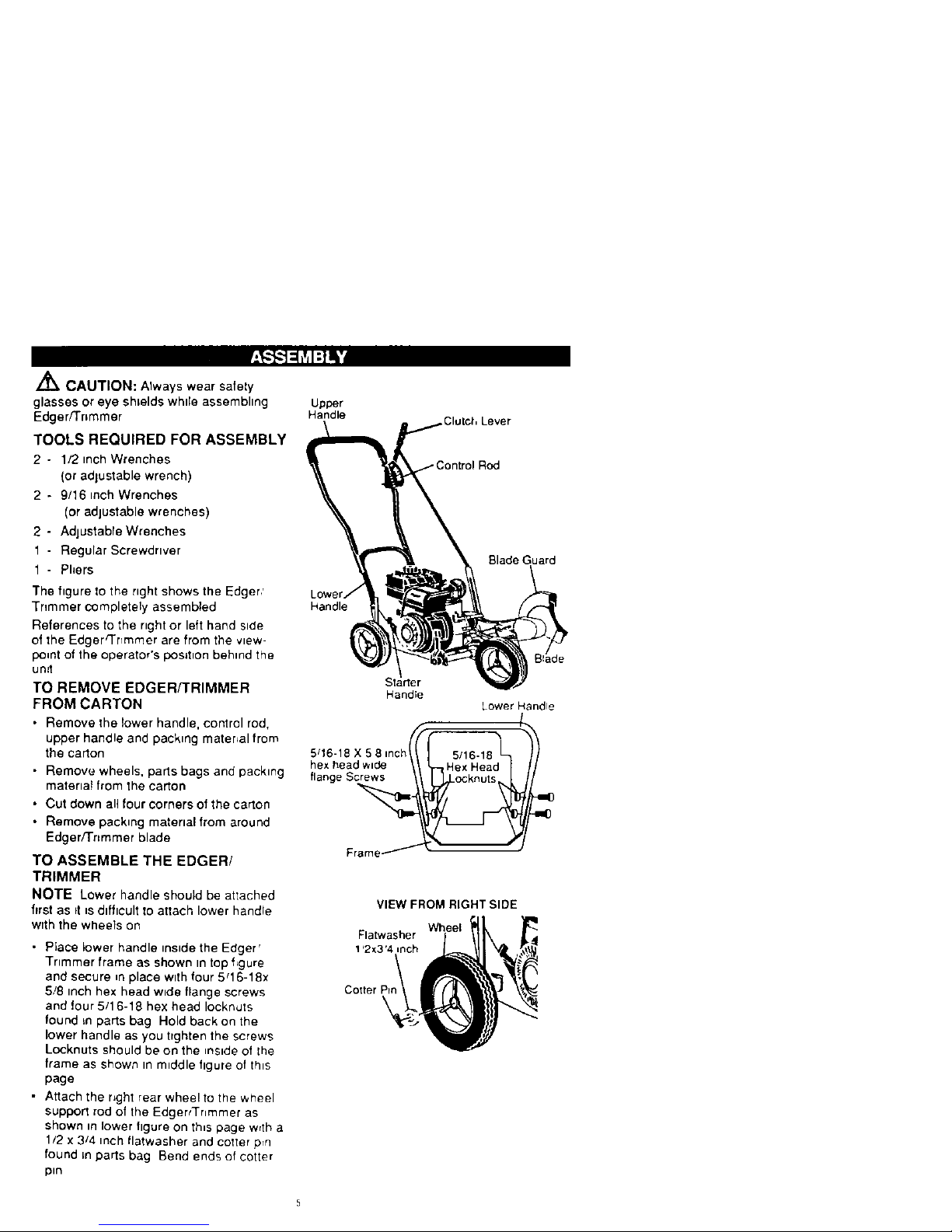
The figure to the nght shows the Edger,'
Tnmmer completely assembled
References to the nght or left hand side
of the Edger_nmmer are from the view-
po=nt of the operator's position behind the
unit
TO REMOVE EDGERf'FRIMMER
FROM CARTON
• Remove the lower handle, control rod,
upper handle and packing matenal from
the carton
• Remove wheels, parts bags and packing
materlat from the carton
• Cut down all four corners of the carton
• Remove packing material from around
Edger/Trtmmer blade
TO ASSEMBLE THE EDGER/
TRIMMER
NOTE Lower handle should be attached
first as it _sdifficult to attach lower handle
with the wheels on
• Place lower handle inside the Edger'
Trimmer frame as shown in top f_gure
and secure _nplace with four 5q6-18x
5/8 inch hex head wide flange screws
and four 5/1 6-18 hex head IockmJtS
found _n parts bag Hold back on the
lower handle as you tighten the screws
Locknuts should be on the reside of lhe
frame as shown m middle figure of this
page
• Attach the right rear whee! to the wheel
support rod of the EdgertTr_mmer as
shown in lower figure on this page wrth a
1/2 x 3/4 inch Ilatwasher and cotter prn
found =nparts bag Bend ends of cotter
pin
Upper
Handle
,Clutch Lever
Slade Guard
Handle
Starter
Handle
Lower Handle
/.
5q6-18 X 5 8 inch _5/16.18
hexheadw_de ,H_xH_ad I
flange Screws
Frame _ ,
=0
m0
VIEW FROM RIGHT SIDE
Wheel
Flatwasher
1'2_3'4 inch
Cotter P=

• Attach the left rear wheel to the Edger/
Trimmer shown in figure below w_th a
3/8-16 x 1 40 inch shoulder bolt, spacer
and 3/8-16 hex head jam nut found in
parts bag
VIEW FROM INSIDE LEFT REAR WHEEL
S_acer
( 10 inch Io,,g)
Shoulder Bolt
3/8-16
Jam Nut _-
• Attach the front wheel to the Edger/
Trimmer shown in figure below wElha
5/16-18 x 3 00 inch hex head screw, two
11/32 x 11/16 inch flatwashers, one
spacer and a 5/16-18 hex head wide
flange Focknut found in parts bag
VIEW FROM FRONT
5q6 !8 Wide
Flange Locknut
11/32x 11!16 Inch
11/32x11,16 Inch
eel
Screw (1 39 Inch Long)
5/16-18x3 Inches
• Place the upper handle on the lower
handle as shown in next hgure and ahgn
upper handle holes m lower handle and
secure in place with four 5q6-18 x 1 -I_4
rnch hex head screws and four 5/16-18
hex head Iocknuts found m parts bag
Locknuts should be to the reside of the
two handles as shown
• The clutch lever is located on the left
hand side of upper handle when properly
installed Insert one end of the control rod
from left to right through the hole m the
clutch lever and attach wrth a hair pin
found in parts bags See next figure
• Place the clutch lever m the first depth
selection and insert the other end of the
control rod through the hole in the qu[ll
support arm Attach with halrppn found _n
parts bag
• Move the clutch lever to rearmost
NEUTRAL posrt_on and latch =n
• If =tis dtfficult to get the clutch lever rote
NEUTRAL. rt may be necessary to loosen
the four screws and nuts holding the
lower handles to the frame as shown in
hrst figure on page 7 Pry up (forward) on
the handles only enough 1oallow the
clutch lever to freely enter the NEUTRAL
posd_on Re-t=ghten nuts and screws
When the clutch lever is tn NEUTRAL the
qudl support arm should be close to the
spacer and screw behind tt as shown
below
Upper Handles
Lever
Rod
Lockn_ts
Qudl
x1-1/4
Hex Head
Screw
Handle
Oudl
Arm
VIEW FROM RIGHT SIDE OF UNIT
FlughtS=de
Lower Handre
J CHECKLIST
Before you operate and enjoy your new
Edger/Trimmer, we wtsh toassure that you
recmve the best performance and satisfac-
tionfromth=squality producL
PLEASE REVIEW THE FOLLOWING
CHECKLIST
_' All assembly instructions have been
completed
4' No remaining loose parts vncarton
•1" All fasteners have been properly in-
stalled and t=ghtened
Wh=lelearnmg how to use your Edger/
Trimmer, pay extra attent=onto the follow-
mg important items"
4'#' Engineotl ts at proper level
/,/' Fuel tank =s filled wdh fresh, clean,
regular Unleaded gasohne
,f#' Become famdiar wnthallcontrols-thmr
location and function Operate controls
before startingengine
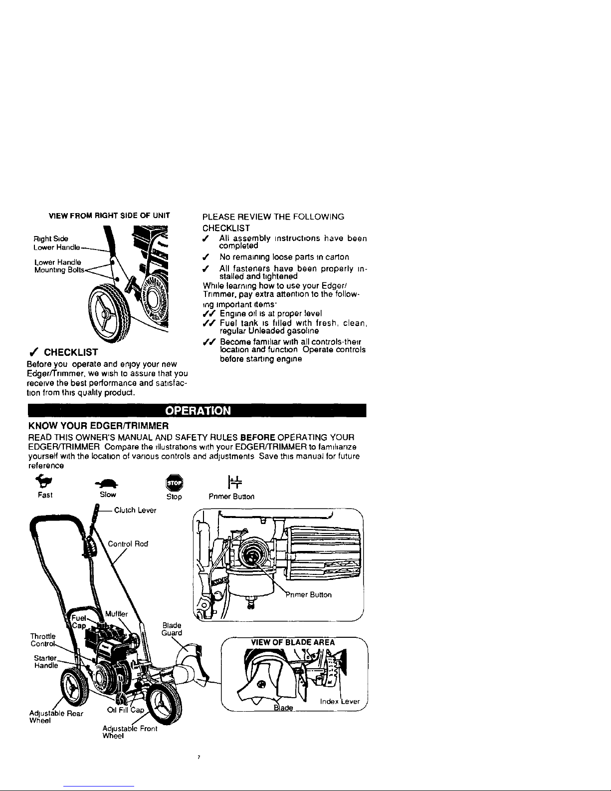
KNOW YOUR EDGER/TRIMMER
READ THIS OWNER'S MANUAL AND SAFETY RULES BEFORE OPERATING YOUR
EDGER/TRIMMER Compare the fllustrat=onsw=thyour EDGER/TRIMMER to famlhanze
yourselfw_ththe location of various controls and adjustments Save this manual for future
reference
Fast Slow Stop PrimerButton
Control Rod
Throttle
Control._
Starter
Blade
Guard
VIEW OF BLADE AREA
Ad ustable Rear OII F
Whee
AdJustable Front
Wheel
Throttle Control - Used to control the en-
gine speed.
Primer Button - Injectsfuel directlyinto the
carburetor manifold for faster starts.
Starter Handle - The engineon this Edger/
Trimmer is equipped with aneasy pui)recoil
starter.
Clutch Lever - Used to start and stopthe
blade and controlthe depth of cut.
Blade Guard - Used to prevent stones or
other material from being thrown at theop-
erator.
Index Lever - Permits adjustmentfromthe
edging (vertical) positionto trimming (hod-
zontal) position.To change position,pullthe
index lever and rotate the quillassembly to
the desired angle or position.
Adjustable Rear Wheel - Rightrear wheel
is adjustable to level Edger/Trimmer when
edging along a curb(curb-hopping).
Adjustable Front Wheel - Front wheel is
adjustable from side-to-side for balance.
Also, can be adjusted down for curb-hop-
ping.
HOW TO USE YOUR EDGER
/_ WARNING: The operationof this
Edger/Trimmer can resutt inforeign objects
being thrown intothe eyes, whichcan cause
severe eye damage. Always wear safety
glasses or eye shields while operating the
Edger/Trimmer.
We recommend standard safety glasses or
Wide Vision Safety Mask for over your
glasses.
TO STOP EDGER/TRIMMER
• To stop the engine, make sure the clutch
lever is all the way back or up and move
the throttle control lever to the STOP
siton.
Z_ CAUTION: Never leave the Edger/
Trimmer unattended white the engine is
running. Always disengage the cutting blade
and stop the engine.
TO USE THROTI'LE CONTROL
• Run at fullengine speed during normal
use.
• Push throttle control lever up to fncrease
speed; down to decrease speed.
TO USE PRIMER BUTTON
• Push primer button five times. See page 7
figure for location. Wait about two
8
seconds between each push.
• Do not useprimer button to restarta
warm engine after a short shutdown.
TO USE THE CLUTCH LEVER
• Start the engine and move the clutch
lever forward or downto engage the
cuttingblade.
• Selectthe edging depthyou need.
There are 5 selectionsup to2-3/4
inchesdeep.
IMPORTANT: If vary deep edgingis
required, we recommendthat a shal-
low cutbe made first, then cuts at
greater depths until the desired depth
isobtained.
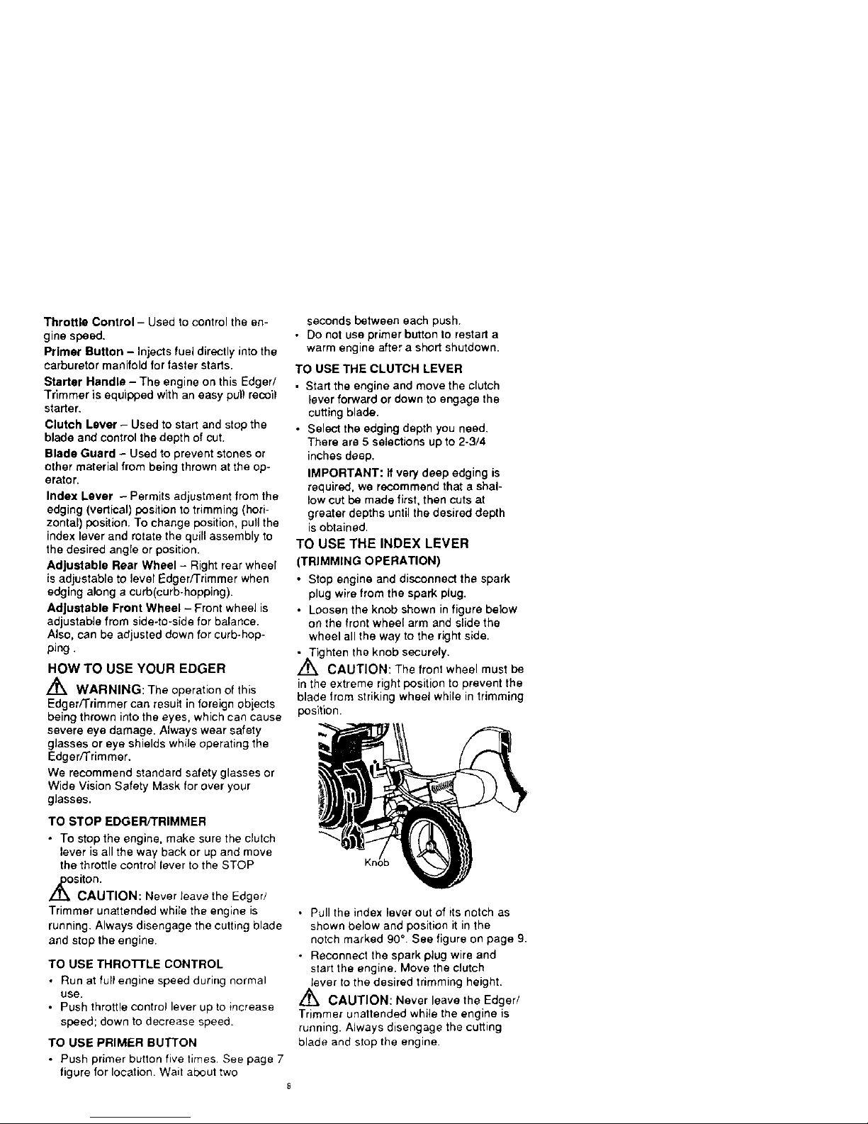
TO USE THE INDEX LEVER
(TRIMMING OPERATION)
• Stop engine and disconnect the spark
plug wire from the spark plug.
• Loosen the knob shown infigure below
on the front wheel arm and slide the
wheel all the way to the right side.
• Tighten the knob securely.
/_ CAUTION: The front wheel must be
in the extreme right position to prevent the
blade from striking wheel while in trimming
position.
• Pull the index lever out of its notch as
shown below and position it in the
notch marked 90 ° . See figure on page 9.
• Reconnect the spark plug wire and
start the engine. Move the clutch
tever to the desired trimming height.
,_ CAUTION: Never leave the Edger/
Trimmer unattended while the engine is
running. Always disengage the cutting
blade and stop the engine.
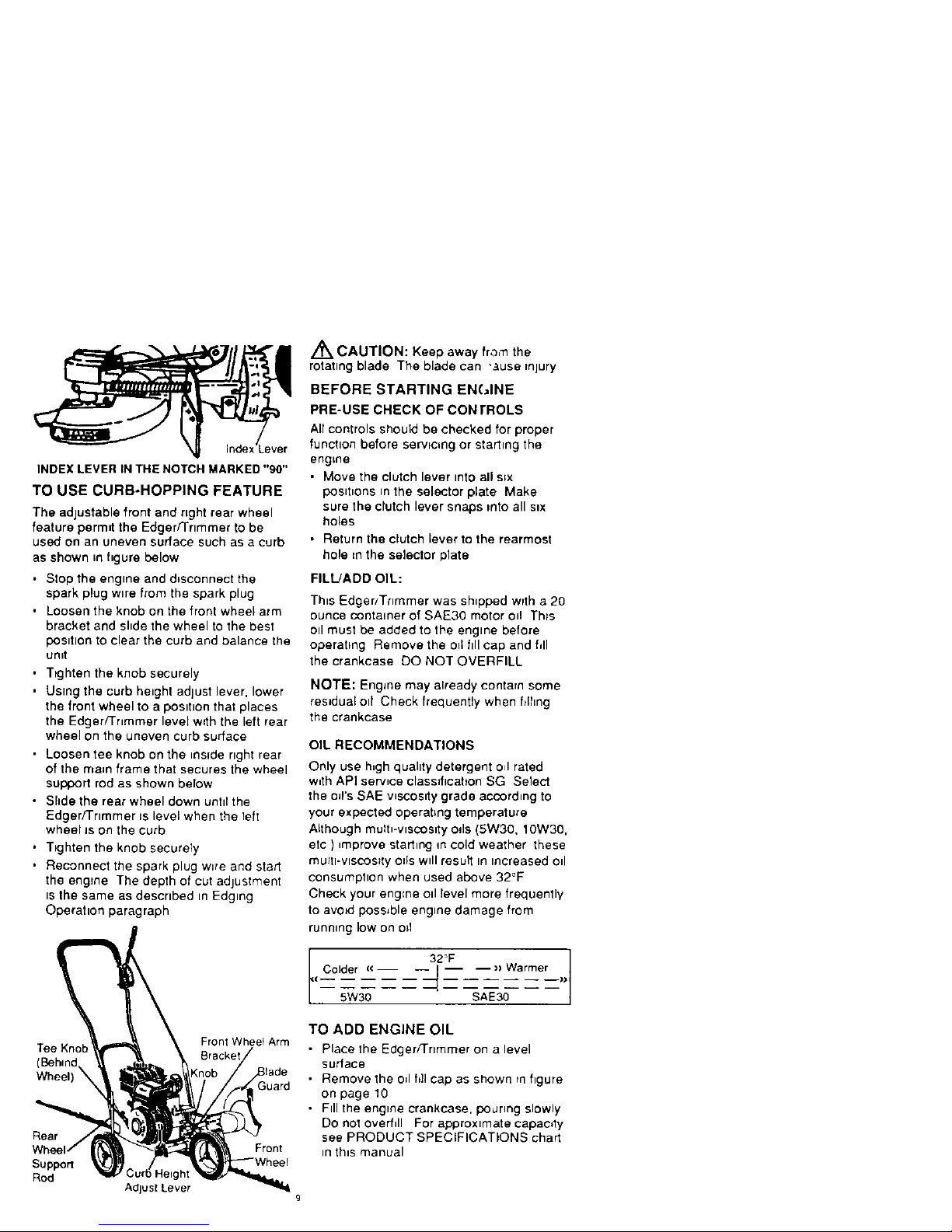
INDEX LEVER IN THE NOTCH MARKED "90"
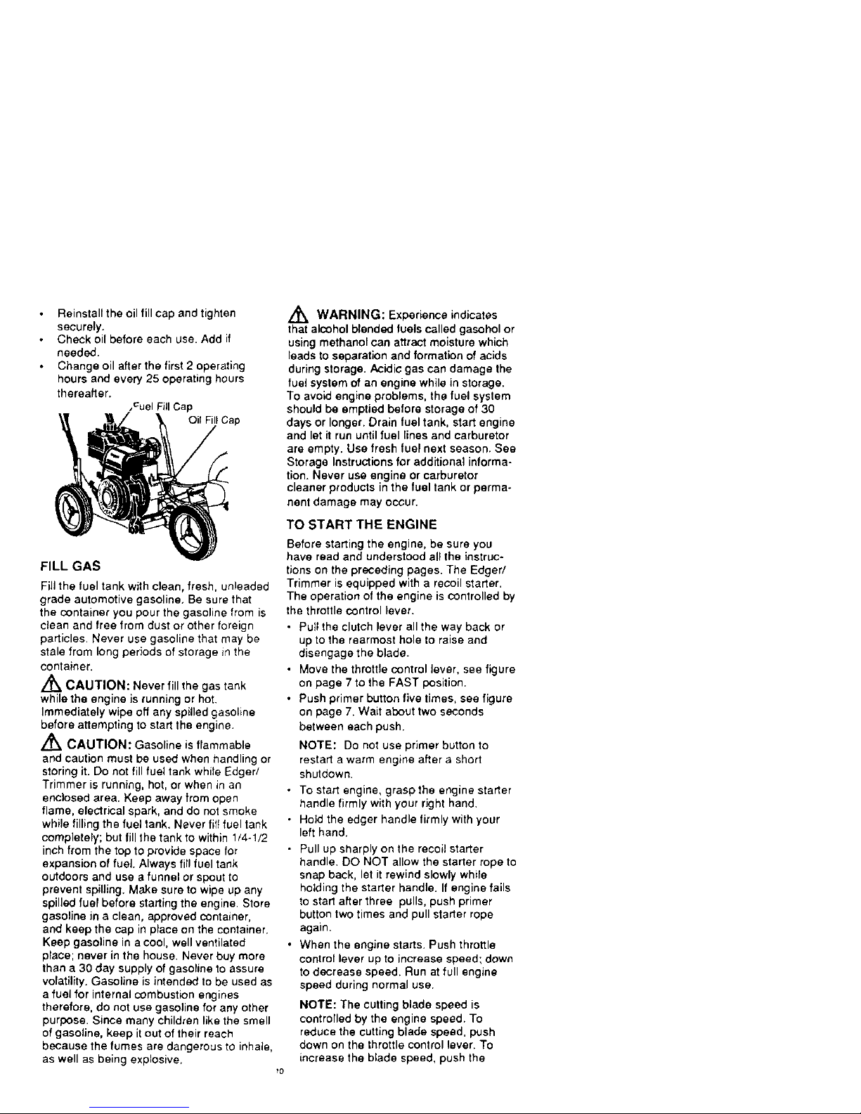
TO USE CURB-HOPPING FEATURE
The adjustable front and right rear wheel
feature permit the Edger/Trimmer to be
used on an uneven surface such as a curb
as shown in figure below
• Stop the engine and disconnect the
spark plug wtre from the spark plug
• Loosen the knob on the front wheel arm
bracket and shde the wheel to the best
posttlon to clear the curb and balance the
unit
•Ttghten the knob securely
• Using the curb height adjust lever, lower
the front wheel to a posttton that places
the Edger/Tnmmer level with the left rear
wheel on the uneven curb surface
• Loosen tee knob on the reside right rear
of the rnam frame that secures the wheel
support rod as shown below
• Shde the rear wheel down unttlthe
Edger/'i'rtmmer ts level when the left
wheeIJs on the curb
• T_ghten the knob securely
• Reconnect the spark plug w=re and start
the engine The depth of cut adjustment
ts the same as descrtbed m Edging
Operation paragraph
Tee Kno Front Wheet Arm
(Behind
Wheel) _
Guard
Rear
Support
Rod
Adjust Lever
Front
/_ CAUTION: Keep away fra,'n the
rotating blade The blade can "Ruse injury
BEFORE STARTING EN(JINE
PRE-USE CHECK OF CON rROLS
Air controls should be checked for proper
function before servicing or starting the
engine
• Move the clutch lever mto all s_x
postt_ons tn the selector plate Make
sure the clutch lever snaps rote all six
holes
• Return the clutch lever to the rearmost
hole =n the selector plate
FILtJADD OIL:
This Edger/Trimmer was shipped with a 20
ounce container of SAE30 motor oil Th_s
Oll must be added to the engine before
operating Remove the o_1ftll cap and fill
the crankcase DO NOTOVERFILL
NOTE: EngJne may already contarn some
residual eli Check frequently when filhng
the crankcase
OIL RECOMMENDATIONS
Only use h_gh quahty detergent o_lrated
w_th API service classification SG Select
the o_rs SAE wecoslty grade according to
your expected operating temperature
Although mulh-wscoslty OdS(5W30, 10W30,
etc ) _mprove starting m cold weather these
mu_h-VlSCOS_IyOtis wdl result In increased od
consumptton when used above 32°F
Check your engEne Oll level more frequently
to avoid possible engine damage from
running low on o=1
Colder (€ __)> _Warmer___))
(
5W30
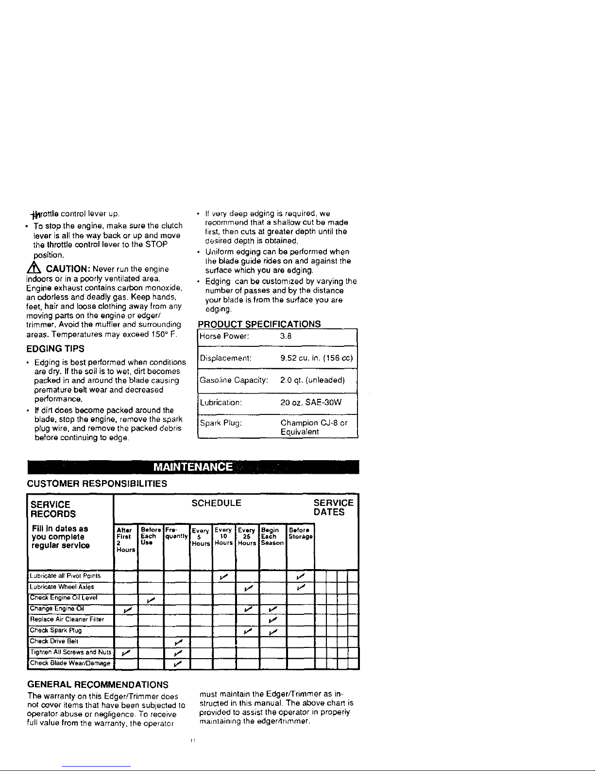
TO ADD ENGINE OIL
• Place the Edger/]rtmmer on a level
surface
• Remove the o;I ft]l cap as shown tn hgure
on page 10
• Ftll the engine crankcase, poJrmg slowly
Do not overfill For approximate capaoty
see PRODUCT SPECIFICATIONS chart
in th_s manual
Reinstalltheoilfillcapandtighten
securely.
Checkoilbeforeeachuse.Addif
needed.
Changeoilafterthefirst2operating
hoursandevery25operatinghours
thereafter.
_CuelFill Cap
Oil Fill Cap
FILL GAS
Fill the fuel tank with clean, fresh, unleaded
grade automotive gasoline, Be sure that
the container you pour the gasoline from is
clean and free from dust or other foreign
particles. Never use gasoline that may be
stale from long periods of storage in the
container.
/_ CAUTION: Never fill the gas tank
while the engine is running or hot.
Immediately wipe off any spilled gasoline
before attempting to start the engine.
,_ CAUTION: Gasoline is flammable
and caution must be used when handling or
storing it. Do not fill fuel tank while Edger/
Trimmer is running, hot, or when in an
enc)osed area. Keep away from open
flame, electrical spark, and do not smoke
while filling the fuel tank. Never lilt fuel tank
completely; but fill the tank to within 1/4-!/2
inch from the top to provide space for
expansion of fuel. Always fill fuel tank
outdoors and use a funnel or spout to
prevent spilling. Make sure to wipe up any
spilled fuel before starting the engine. Store
gasoline in a clean, approved container,
and keep the cap in place on the container.
Keep gasoline in a cool, well ventilated
place; never in the house. Never buy more
than a 30 day supply of gasoline to assure
volatility. Gasoline is intended to be used as
a fuel for internal combustion engines
therefore, do not use gasoline for any other
purpose. Since many children like the smell
of gasoline, keep it out of their reach
because the fumes are dangerous to inhale,
as well as being explosive.
,_ WARNING: Experience indicates
that alcohol blended fuels called gasohol or
using methanol can attract moisture which
leads to separation and formation of acids
during storage. Acidic gas can damage the
fuel system of an engine while in storage.
To avoid engine problems, the fuel system
should be emptied before storage of 30
days or longer. Drain fuel tank, start engine
and let it run until fuel lines and carburetor
are empty. Usa fresh fuel next season. See
Storage Instructions for additional informa-
tion. Never use engine or carburetor
cleaner products in the fuel tank or perma-
nent damage may occur.
TO START THE ENGINE
Before starting the engine, be sure you
have read and understood all the instruc-
tions on the preceding pages. The Edged
Trimmer is equipped with a recoil starter.
The operation of the engine is controlled by
the throttle control lever.
• Pull the clutch lever all the way back or
up to the rearmost hole to raise and
disengage the blade.
• Move the throttle control lever, see figure
on page 7 to the FAST position.
• Push primer button five times, see figure
on page 7. Wait about two seconds
between each push.
NOTE: Do not use primer button to
restart a warm engine after a short
shutdown.
• To start engine, grasp the engine starter
handle firmly with your right hand.
• Hold the edger handle firmly with your
left hand.
• Pull up sharply on the recoil starter
handle. DO NOT allow the starter rope to
snap back, let it rewind slowly while
holding the starter handle. If engine fails
to start after three pulls, push primer
button two times and pull starter rope
again.
• When the engine starts. Push throttle
control lever up to increase speed; down
to decrease speed. Run at full engine
speed during normal use.
NOTE: The cutting blade speed is
controlled by the engine speed. To
reduce the cutting blade speed, push
down on the throttle control lever. To
increase the blade speed, push the
_rottlecontrolleverup
• Tostoptheengine,makesuretheclutch
leverisallthewaybackorupandmove
thethrottlecontrollevertotheSTOP
position.
/_ CAUTION: Never run the engine
indoors or in a poorly ventilated area.
Engine exhaust contains carbon monoxide,
an odorless and deadly gas. Keep hands,
feet, hair and loose clothing away from any
moving parts on the engine or edger/
trimmer. Avoid the muffler and surrounding
areas. Temperatures may exceed 150 ° F.
EDGING TIPS
• Edging is best performed when conditions
are dry. If the soil is to wet, dirt becomes
packed in and around the blade causing
premature belt wear and decreased
performance.
• If dirt does become packed around the
blade, stop the engine, remove the spark
plug wire, and remove the packed debris
before continuing to edge.
• If very deep edging is required, we
recommend that a shaltow cut be made
first, then cuts at greater depth until the
desired depth is obtained.
• Uniform edging can be performed when
the blade guide rides on and against the
surface which you are edging.
• Edging can be customized by varying the
number of passes and by the distance
your blade is from the surface you are
edging.
PRODUCT SPECIFICATIONS
Horse Power: 3.8
Displacement: 9.52 cu. in. (156 c¢)
Gasoline Capacity: 2.0 qt, (unleaded)
Lubrication: 20 oz, SAE-30W
Spark Plug: Champion CJ-8 or
Equivalent
CUSTOMER RESPONSIBILITIES
SERVICE
RECORDS
Fill in dates as
you complete
regular service
Lubricate all Pivot Points
Lubricate Wh_l Axles
Check Engine Oil Level
Change Engine Oil
Replace Air Cleaner Filter
Check Spark Plug
Check Drive Belt
Tighten All Screws and Nu[s
Check Blade Wear/Damage
After
First
2
Hours
Be|ore =re-
Each luenny
Use
V"
SCHEDULE SERVICE
DATES
Every _Every I
Every
10 | 2_ I
5
Hours Hours I Hours I
v"
• ;t
• ;!'
I
Begin Before
Eacft Storage
Season
v"
GENERAL RECOMMENDATIONS
The warranty on this Edger/Trimmer does
not cover items that have been subjected to
operator abuse or negligence. To receive
full value from the warranty, the operater
must maintain the Edger/Trimmer as in-
structed in this manual. The above chart is
provided to assist the operator in properly
maintaining the edger/trimmer.
11
LUBRICATION
• After each 25 hours of use of your edger/
trimmer, apply lightmachine oil to all
moving parts, particularly the wheels.
• The oil in the engine crankcase must be
changed after the first 2 hours of opera-
tion and after each 25 hours of use there-
after. See OIL RECOMMENDATIONS in
OPERATIONAL sectional in this manual
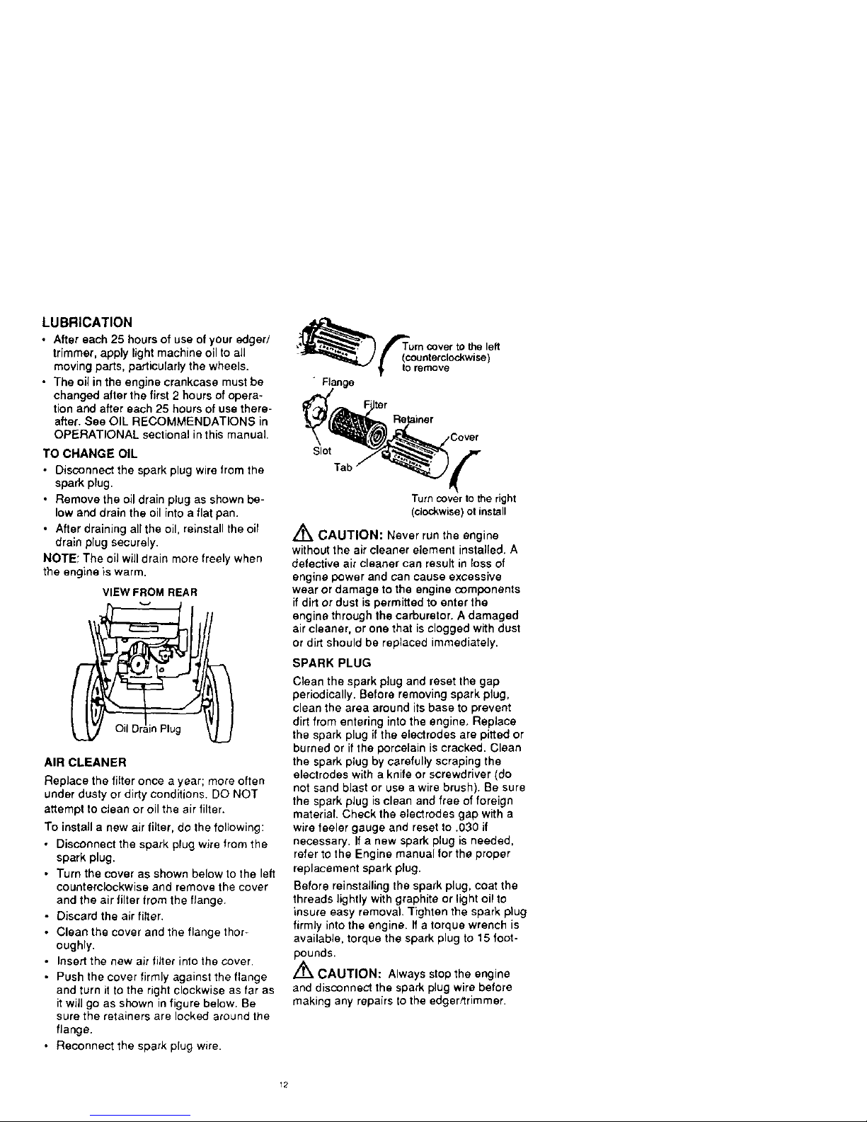
TO CHANGE OIL
• Disconnect the sparkplugwire from the
spark plug.
• Remove the oildrainplug as shown be-
low and drain the oil into a flatpan.
• After draining all the oil,reinstallthe oil
drain plug securely.
NOTE; The oil will drain mare freely when
the engine is warm.
VIEW FROM REAR
il Drain Plug
AIR CLEANER
Replace the filter once a year; more often
under dusty or dirty conditions. DO NOT
attempt to clean or oil the air filter.
To instaif a new air filter, do the following:
• Disconnect the spark plug wire from the
spark plug.
• Turn the cover as shown below to the left
counterclockwise and remove the cover
and the air filter from the flange.
• Discard the air filter.
• Clean the cover and the flange thor+
oughly,
• Insert the new air filter into the cover.
• Push the cover firmly against the flange
and turn it to the right clockwise as far as
it will go as shown in figure below. Be
sure the retainers are locked around the
flange,
• Reconnect the spark plug wire.
• Flange
Slot
Tab
Turn cover to the right
(clockwise) ot install
Z_ CAUTION: Never run the engine
without the air cleaner element installed. A
defective air cleaner can result in loss of
engine power and can cause excessive
wear or damage to the engine components
if dirt or dust is permitted to enter the
engine through the carburetor. A damaged
air cleaner, or one that is clogged with dust
or dirt should be replaced immediately.
SPARK PLUG
Clean the spark plug and reset the gap
periodically. Before removing spark plug,
clean the area around its base to prevent
dirt from entering into the engine, Replace
the spark plug if the electrodes are pitted or
burned or if the porcelain is cracked. Clean
the spark plug by carefully scraping the
electrodes with a knife or screwdriver (do
not sand blast or use a wire brush). Be sure
the spark plug is clean and free of foreign
material. Check the electrodes gap with a
wire feeler gauge and reset to .030 if
necessary. If a new spark plug is needed,
refer to the Engine manual for the proper
replacement spark plug.
Before reinstalling the spark plug, coat the
threads lightly with graphite or light oil to
insure easy removal. Tighten the spark plug
firmly into the engine. If a torque wrench is
available, torque the spark plug to 15 foot-
pounds.
/'_ CAUTION: Always stop the engine
and disconnect the spark plug wire before
making any repairs to the edgerttrimmer.
12
 Loading...