

Page 1
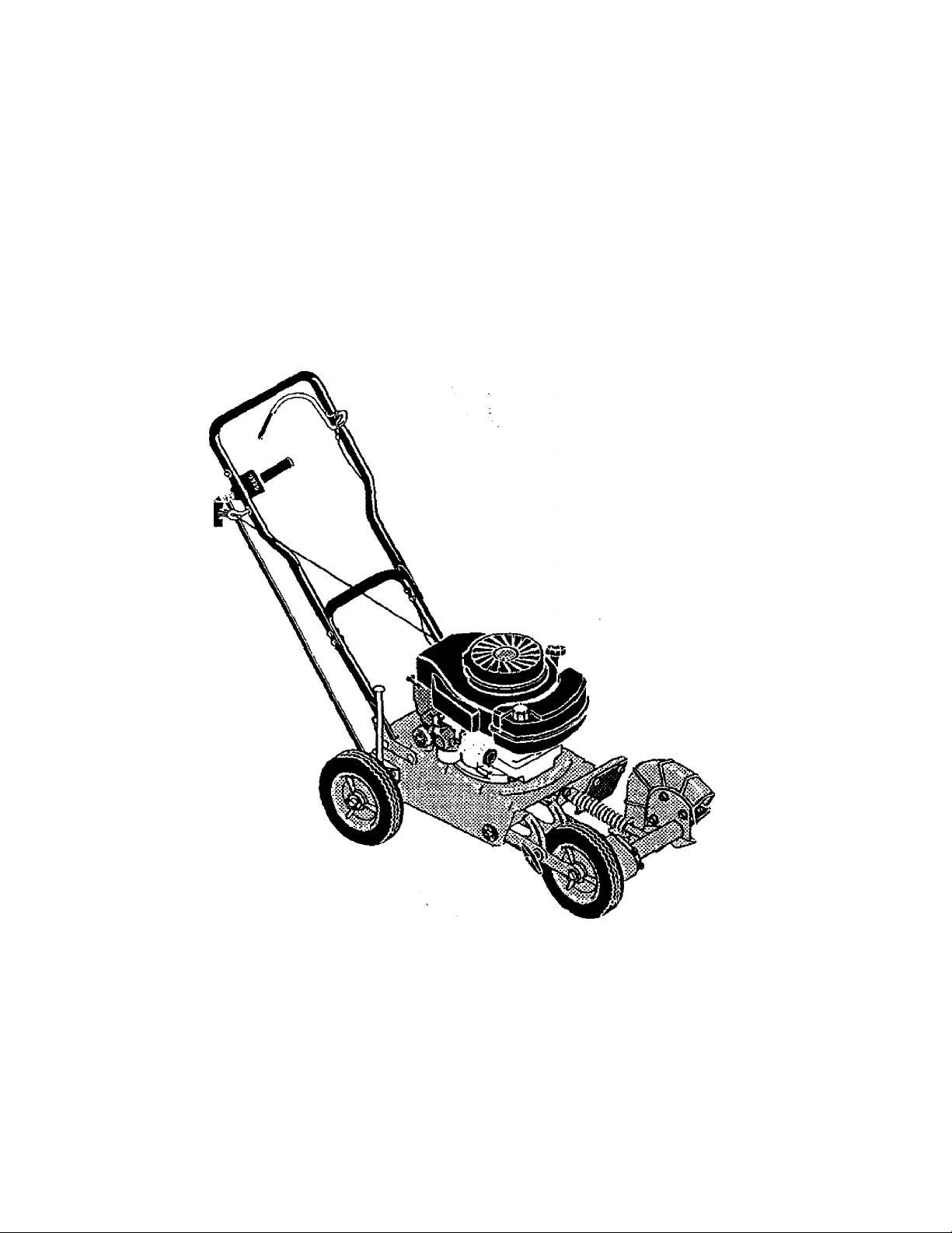
CRAFTSMAN
4 Horsepower
9 Inch
EDGER
MODEL NO.
536.797400
Caution:
Read and follow all Safety
Rules and Operating
Instructions before first use
of this product.
SEARS, ROEBUCK AND CO., Hoffman Estates, IL 60179 U.S.A.
711044 04/11/97
Page 2

TABLE OF CONTENTS
Table of Contents 2
Warranty 2
Safety Rules 2-3
Contents of Shipping Carton 4
Assembly 4-6
Operation 7-10
Maintenance 11-12
Service and Adjustments
Storage
Troubleshooting
Edger Repair Parts
Engine Repair Parts
Spanish(Espahol)
Parts Ordering/Service
Back Cover
WARRANTY STATEMENT
LIMITED TWO-YEAR WARRANTY ON CRAFTSMAN EDGER
For two years from the date of purchase, when this Craftsman Edger is maintained, lu
bricated, and tuned up according to the operating and maintenance instructions in the
owner's manual, Craftsman will repair, free of charge, any defect in material or work
manship.
If this Craftsman Edger is used for commercial or rental purposes, this warranty ap
plies for only 90 days from the date of purchase.
This warranty does not cover the following;
• Expendable items which become worn during normal use, such as spark plugs, etc.
• Repairs necessary because of operator abuse or negligence, including bent crank
shafts and the failure to maintain the equipment according to the instructions con
tained in the owner's manual. '*
WARRANPr' SERVICE IS AVAILABLE BY RETURNING THE CRAFTSMAN EDGER
TO THE NEAREST CRAFTSMAN SERVICE CENTEFIDEPARTMENT IN THE
UNITED STATES. THIS WARRANTY APPLIES ONLY WHILE THIS PRODUCT IS IN
USE IN THE UNITED STATES.
This warranty gives you specific legal rights, and you may also have other rights which
may vary from state to state.
Sears, Roebuck and Co., D817WA, Hoffman Estates, IL 60179
13-14
15
16
17-20
21-24
25-41
SAFETY RULES
Look for this symbol to point, out lirportant safety precautions. It means-
A
ATTENTION!!! Become alert!!! Your safety is involved.
CAUTION: Always disconnect spark
plug wire and place wire where it cannot
contact spark plug to prevent accidental
starting when setting-up, transporting,
adjusting or making repairs.
IMPORTANT: Safety standards require
operator presence controls to minimize the
risk of injury. Your Edger is equipped with
such controls. Do not attempt to defeat the
function of the operator presence control
under any circumstances..
BEFORE USE
• Read the owner's manual carefully. Be
thoroughly familiar with the controls and
the proper use of the Edger. Know how to
stop the edger and disengage the
controls quickly.
• Do not oneretfl the Fdner without
footwear that will improve footing on
slippery surfaces.
• Keep the area of operation clear of all
persons, particularly small children and
pets.
• Thoroughly inspect the area where the
Edger is to be used and remove all
foreign objects.
FUEL SAFETY
• Handle fuel with care; it is highly flam
mable.
• Use an approved container.
• Check fuel su|:^ly before each use,
allowing space for expansion as the heat
of the engine and/or sun can cause fuel to
expand.
• Fill fuel tank outdoors with extreme care.
Never fill fuel tank indoors. Replace fuel
tank can <;eciirelv end wioe uo soitled
Page 3

• Never remove the fuel tank cap or add
fuel to a running or hot engine.
• Never store fuel or Edger with fuel in the
tank inside a building where fumes may
reach an open flame.
OPERATING SAFETY
• Never aliow children or young teenagers
to operate the Edger. Keep them away
while it is operating. Never allow adults to
operate the Edger without proper
instruction.
• Do not operate this machine if you are
taking drugs or other medication which
can cause drowsiness or affect your
ability to operate this machine.
• Do not use this machine if you are
menially or physically unable to operate
this machine safely.
• Always wear safety glasses or eye
shields during operation or while perform
ing an adjustment or repair to protect
your eyes from foreign objects that may
be thrown from the Edger.
• Do not put hands or feet near or under
rotating parts.
• Exercise extreme caution when operating
on or crossing gravel drives, walks, or
roads. Stay alert for hidden hazards or
traffic.
• Exercise caution to avoid slipping or
falling.
• Never operate the Edger without proper
guards, plates, or other safety protective
devices in place.
• Never operate the Edger at high transport
speeds on slippery surfaces. Look behind
and use care when backing.
• Never allow bystanders near the Edger.
• Keep children and pets away while
operating.
• Never operate the Edger without good
visibility or light.
• Do not run the engine indoors. The
exhaust fumes are dangerous, containing
CARBON MONOXIDE, an ODORLESS
and DEADLY GAS.
• Take all possible precautions when
leaving the Edger unattended. Stop the
engine.
• Do not overbad the Edger capacity by
attempting to edge too deep at too fast a
rate.
SAFE STORAGE
• Always refer to the owner's manual
instructions for important details if the
Edger is to be stored for an extended
period.
• Never store the edger with fuel in the fuel
tank inside a building where ignKion
sources are present such as water and
space heaters, clothes dryers, and the
like. Allow the engine to cool before
storing in any enctosure,
• Keep the Edger in safe wrarking condition. |
Ched< all fasteners at frequent intervals
for proper tightness.
REPAIR/ADJUSTMENTS SAFETY
• After striking a foreign object, stop the
engine (motor). Remove the wire from the
spark plug, and keep the wire away from
the plug to prevent accidental starting.
Thoroughly inspect the Edger for any
damage, and repair the damage before
restarting and operating it.
• if edger should start to vibrate abnormally,
stop engine (motor) and check immedi
ately for the cause. Vibration is generally
a warning of trouble.
• Stop the blade whenever you leave the
operating position. Also, disconnect the
spark plug wire before unclogging the
blade and when making any repairs,
adjustments, or inspections.
• When cleaning, repairing, or inspecting,
shut off the engine and make certain all
moving parts have stopped.
• Never attempt to make any adjustments
while the engine is running except when
specifically recommended by the manu
facturer.
A
WARNING: The engine exhaust
from this product contains chemicals
known to the State of California to cause
cancer, birth defects or other reproductive
harm.
A WARNING : This unit is equipped with
an internal combustion engine arid should
not be used on or near any unimproved for
est-covered, brush-cove red or grass-cov
ered land unless the engine's exhaust sys
tern is equipped with a spark arrester meet
ing applicable local or state laws (if any). If a
spark arrester is used, it should be main
tained in effective working order by the op
erator.
in the state of California the spark arrester is
required by law (Section 4442 of the Califor
nia Public Resources Code). Other states
may have similar laws. Federal laws apply
on federal lands. A spark arrester/muffler is
available through your nearest Craftsman
Authorized Sen/ice Center (See ENGINE
REPAIR PARTS section in this manual).
Page 4
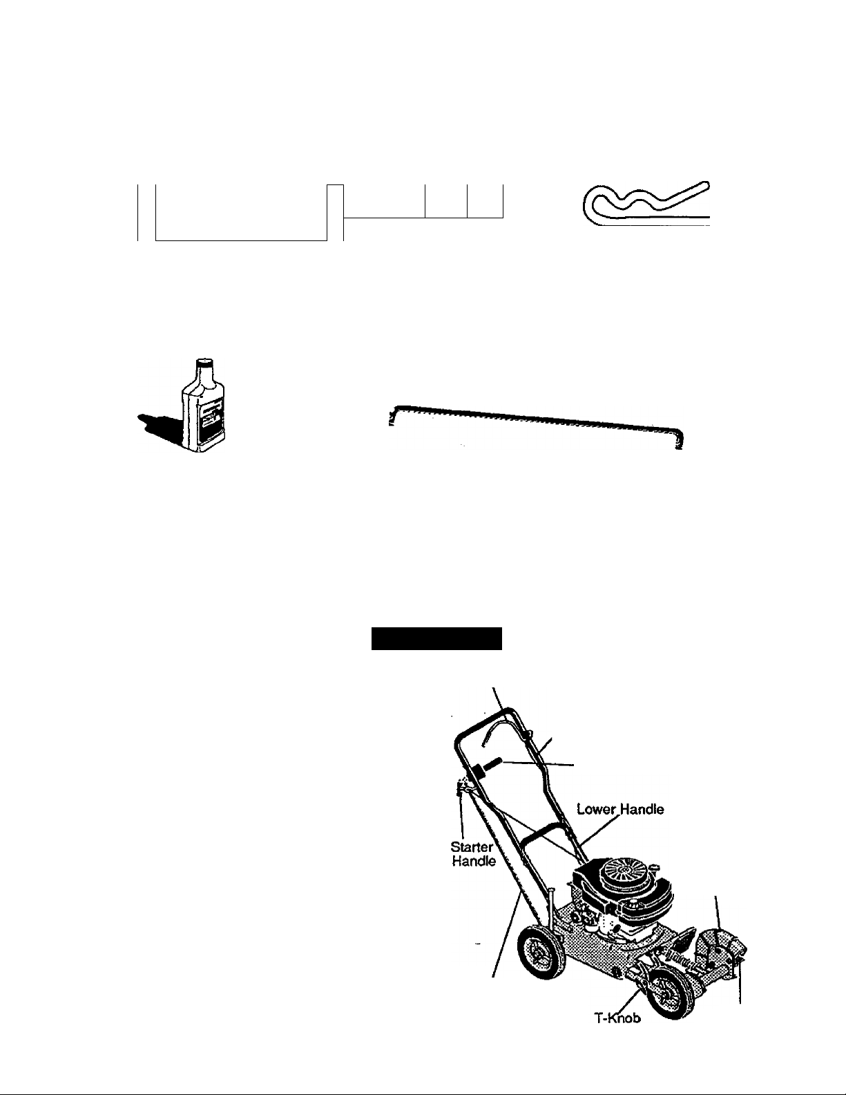
Contents of Parts Bag (shown full size)
X
I—
(2) • Hex Head Nuts
S/16-18
r
(2)-Hex Head Screws
5/16-18X 1-1/4 inch
ii:
;
Parts packed separately in carton (not shown full size)
1 • Container SAE30 Oil(20 ounces)
1 - Owner's Manual (not shown)
1 - Parts Bag (not shown)
(1) -Control Rod
(2) • Hair Pins
ASSEMBLY
AcaUTION: Always wear safety
glasses or eye shields while assembling
Edger.
TOOLS REQUIRED FOR ASSEMBLY
1 - 7/16 inch Wrench
(or adjustable wrench)
2 - 1/2 inch Wrenches .
(or adjustable wrenches)
1 - Pair Pliers
The figure to the right shows the Edger
completely assembled. -
References to the right or left hand side
of the Edger are from the viewpoint of the
operator's position behind the unit.
TO REMOVE EDGER FROM CARTON
• Remove the control rod and packing
material from carton
• Cut down all four corners of the carton.
Engine Control Lever
clipper Handle
—Depth Control Lever
Blade Guard
Control Rod
Blade
Page 5
TO ASSEMBLE THE EDGER
• Pivot the upper handle upward being
careful not to pinch or pull the engine
control wire, until the mounting holes in
the upper handle align with the mounting
hoies in the lower handle. Install (2) 5/1618x1-1/4 inch hex head screws and (2)
5/16-18 hex lock nuts (found in parts ,
bag) in the empty handle holes and
tighten ail four clamping bolts. Locknuts
should be to the inside of the handles as
shown in figure below.
• All four bolts must be tightened to the
point that the head of the bolt cuts into
the paint on the handles. This will allow a
good connection allowing the engine
control lever to stop the engine when
released.
5/16-18
Hex Head
Locknut
Lower
Handle
Rear
Selection
Contro!
Rod
Loosen the adjustable front wheel T-knob,
and push down on the T-knob until the
front of the unit comes to a resting point.
The engine mounting surface should be
parallel to the surface the unit is resting
on for best edging results.
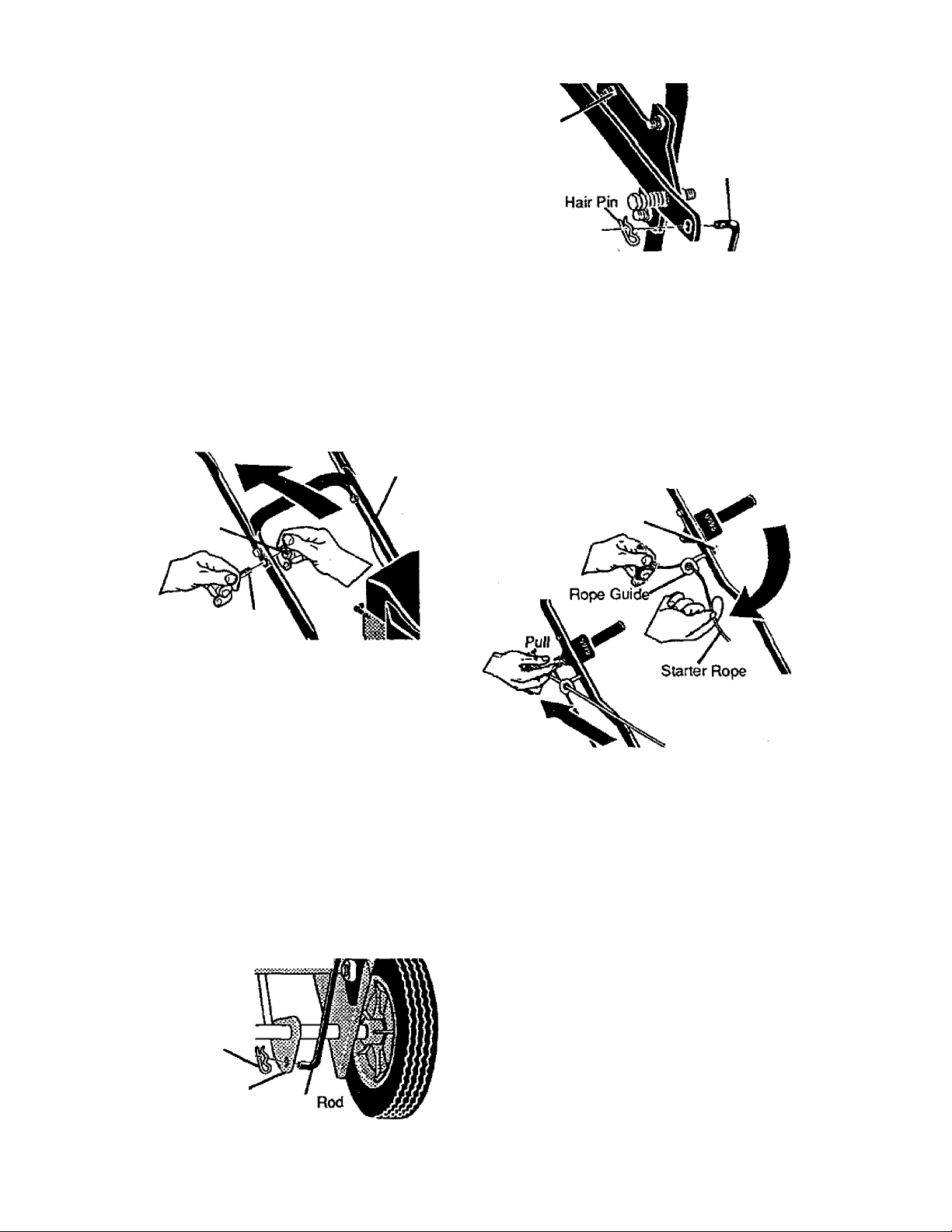
Loosen the rope guide nut (1/4-20 hex
head cenlerlock) located on the inside of
the right handle enough to let starter rof
through as shown below.
Thread starter rope through the guide.
Tighten rope guide nut.
Rope Guide Nut
(1/4-20 Reghexctrik)
5/16-18X1-1/4inch
Hex Head Screw
Insert one end of the control rod from right
to left through the hole in the linkage
bracket located inside the frame on the
rear axle. Attach with hairpin found in
parts bag. See figure below.
Place the depth control lever in the rear
selection slot. While pushing down on the
upper handle to the point that the front
wheel is raised off the ground, pul! up on
the other end of the control rod until you
can insert the end of the control rod from
right to left through the hole in the depth
control lever. Attach with hairpin. See next
figure.
Return depth control lever to the forward
most selection slot for transport and
starting.
Hair Pin
Linkage Bracket
Confrol
✓ CHECKLIST
Before you operate your new Edger, to
ensure that you receive the best perfor
mance and satisfaction from this quality
product, please review the following
checklist:
✓ All assembly instructions have been
completed.
✓ No remaining loose parts in carton.
Keep in safe place.
✓ All fasteners have been properly in
stalled and tightened.
While learning how to use your Edger,
pay extra attention to the following impor
tant Hems:
✓ ✓ Engine oil is at proper level.
✓ ✓ Fuel tank is filled with fresh, clean,
regular Unleaded gasoline.
✓ ✓ Become familiar with all controls, their
location and funclton. Operate controls
before starting engine.
Page 6
OPERATION
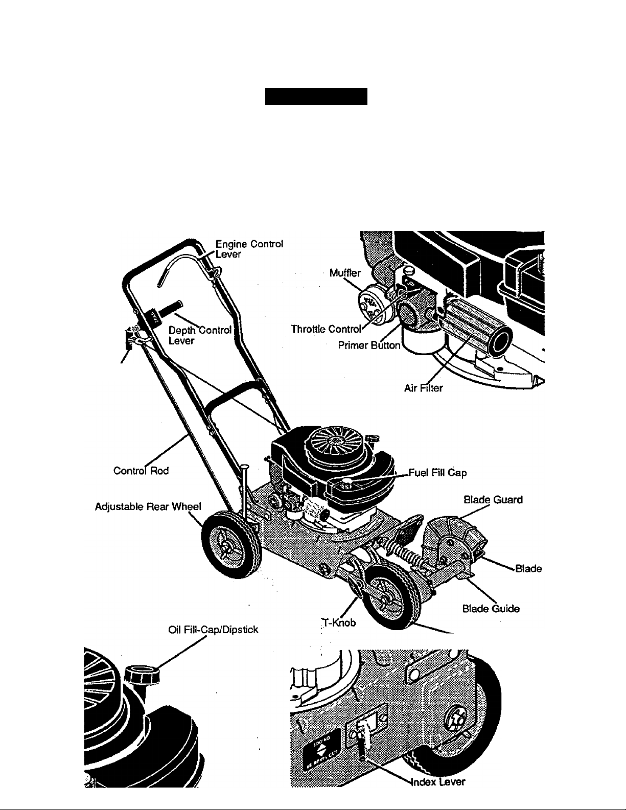
KNOW YOUR EDGER
READ THIS OWNER'S MANUAL AND SAFETY RULES BEFORE OPERATING YOUR
EDGER. Compare the illustrations with your EDGER to familiarize yourself with the location
of various controls and adjustments. Save this manual for future reference.
Starter Handle
Fast Slow
Stop
Primer Button
Adjustable Front Wheel
Page 7

Throttte Control - Used to control the en
gine speed.
Primer Button - injects fuel directly into the
carburetor manifold for faster starts.
Starter Handle - The engine on this edger
is equipped with an easy pud recoil starter.
Depth Control Lever - Controls the depth
of the blade.
Blade Guard - Used to prevent stones or
other material from being thrown at the op
erator.
Engine Control Lever - Must be held back
to allow engine to start and run.
Index Lever - Permits adjustment from the
edging (vertical) position to beveling (45“)
position. To change position, pull the index
lever and rotate the quill assembly to the
desired angle or position.
Adjustable Rear Wheel- Right rear wheel
is adjustable to level Edger when edging
along a curb(curb-hopping). ■ '
AJustable Front Wheel-Front wheel can
be adjusted down for curb-hopping. - '
TO USE THE ENGINE CONTROL
LEVER
• Pull the engine control lever back with
your left hand and hold it in contact with
the upper handle cross tube to allow en
gine to start and run. See next figuro.
• Release the engine control lever to stop
the engine.
NOTE: If engine continues to i^after
lever is released.Use the stop ® position
on the throttle control to stop the engine
and then see your Craftsman Service Cen
ter to correct the engine control lever prob
lem.
CAUTION: Always stop the engine
and make sure all parts have stopped
whenever leaving the operator's position or
when cleaning, replacing or inspecting the
Edger.
Engine Control
Lever
WARNING: Blade is rotating when
engine is running or being started. Keep.
hands and feet away from blade to prevent
injury.
HOW TO USE YOUR EDGER
WARNING: The operation of this
Edger can result in foreign objects being
thrown into the eyes, whidn can cause se
vere eye damage. Always wear safety
glasses or eye shields while operating the
Edger.
We recommend standard safety glasses or
Wide Vision Safety Mask for over your
glasses.
TO STOP EDGER
• Make sure the depth control lever Is all
the way forward and release engine
control lever. There is a ^ STOP
position on the throttle control lever in
case of a failure with the engine control
lever. Wait for all moving parts to stop
before leaving the operator position.
A CAUTION: Never leave the Edger
unattended while the engine is running.
Always raise the cutting blade and Stop the
engine.
TO USE THROTTLE CONTROL
• Run at full engine speed during
normal use.
• Push throttle control lever forward to
increase speed; back to decrease rrfilspeed.
• Pulling the throttle control lever all tfte
way back will stop ^ the engine.
TO USE PRIMER BUTTON
• Push primer button In^five times. See
page 6 figure for tocation. Wait about two
seconds between each push.
NOTE: Do not use primer button to re
start a warm engine after a short shut
down.
Page 8

TO USE THE DEPTH CONTROL
LEVER
• Position your Edger in desired edging lo
cation, before operating.
• Start the engine and move the depth
control lever back to lower the cutting
blade.
• Select the edging depth you need.
There are 4 selections up to approxi
mately 2-1/2 inches deep.
IMPORTANT: If very deep edging is
required, we recommend that a shallow
cut be made first, then cut at greater
depths until the desired depth is, ob
tained.
A WARNING; Keep away from the rotat
ing blade. The blade can cause injury.
TO USE THE INDEX LEVER
(BEVELING OPERATION) *
• Stop engine and disconnect the spark
plug wire from the spark plug. . ,
INDEX LEVER IN THE NOTCH MARKED
BEVEL CUT
■ Pull the index lever out of the edging
notch as shown above and position it in
the notch marked bevel cut.
• Reconnect the spark plug wire and
start the engine. Move the dutch lever
to the desired beveling depth.
• Stop the engine and disconnect the
spark plug wire from the spark plug.
• With the front wheel and the left rear
wheel on the top of the curb and support
ing the Edger with your right hand, reach
into the inside right rear of the main
frame and loosen the fluted knob that se
cures the wheel support rod as shown
below.
• As the fluted knob is loosened the rear
wheel wilt slide dovwi.
• Hold the Edger so that the top of the
main frame is level with the top of the
curb and retighten the fluted knob.
• Turn the Edger so that the front wheel
will be on the same surface as the right
rear wheel. The left rear wheel is on
top of the curb and the right rear wheel
is supporting the Edger on the lower
surface.
• While standing on the right side of the
Edger, loosen the T-knob on the front
wheel bracket.
• With your left hand, lift the front of the
Edger using the T-knob until the main
frame is again level with the top of the
curb.
• With your right hand, push the front
wheel down until the wheel makes con
tact with the surface below.
• Hold the front of the main frame level
with your right hand and retighten the Tknob with your left hand. Check level of
main frame to top of curb and make any
adjustments.
• Reconnect the spark plug wire and start
the engine. The depth of cut adjustment
is the same as described in Edging Op
eration paragraph.
WARNING: Keep away from the rotating
blade. The blade can cause injury.
A CAUTION: Never leave the Edger
unattended while the engine is running.
Prior to adjusting the indexing blade posi
tion, always raise the cutting blade and
stop the engine.
TO USE CURB HOPPING FEATURE
The adjustable front and right rear wheel
feature permits the Edger to be used on
Page 9

TO USE THE BEVEL CUT FEATURE
Bevel edging reduces the need to edge as
often creating a type of trench along your
sidewalk, driveway and etc. Move the in
dex lever to the bevel cut position and se
cure index lever in the slot. Prior to starting
the engine, line the Edger up as if you were
going to bevel cut and move the depth con
trol lever down to test the blade location.
Return the depth control lever to the for
ward slot of the adjustment bracket to raise
the blade. Start the engine and move the
depth control lever to the desired depth of
cut.
BEFORE STARTING ENGINE
TO ADD ENGINE OIL
• Place the Edger on a level surface.
• Remove the oil fill cap/dipstick as shown
in next figure.
• Fill the engine crankcase, pouring slowly.
DO NOT OVERFILL. For approximate
capacity see PRODUCT SPECIFICA
TIONS on page 11 of this manual.
• Reinstall the oil fill cap/dipstick and
tighten securely. Wipe away excess oil.
• Check oil before each use. Add if
needed.
PRE-USE CHECK OF CONTROLS
All controls should be checked for proper
function before servicing or starting the
engine.
• Move the depth control lever into all four
positions in the selector plate. Make sure
the depth control lever snaps irrto'airfour
holes as shown in figure on page 6; '
• Return the depth control lever to the
forward hole in the selector plate.
FILUADD OIL:
This Edger was shipped with a 20 ounce
container of SAE30 motor oil. This oil must
be added to the engine before operating.
Remove the oil fill cap/dipstick and fill the
crankcase to FULL line on dipstick. Your
engine may not require the entire 20
ounces of oil. DO NOT OVERFILL. Tighten
the fill cap/dipstick securely each time you
check the oil level. , ,
OIL RECOMMENDATIONS ' v ^
Only use high quality detergent oil rated
with API service classification SG. Select
the oil's SAE viscosity grade according to
your expected operating temperature:
Colder «
---------
^30 ' 5AP3Ó ^
NOTE: Although multi-viscosity oils (5W30,
10W30, etc.) improve starting in cold
weather, these multi-viscosity oils will result
in increased oil consumption when used
above 32®F. Check your engine oil level
more frequently to avoid possible engine
damage from running low on oil.
32'’F
— I — — » Warmer
Oil Fill Tube
Oil Fill Cap/
Dipstick
CAUTION: Never fill the gas tank
while the engine is running or hot.
Immediately wipe off any spilled gasoline
before attempting to start the engine.
Fuel Fill Cap
FILL GAS:
Fill the fuel tank with clean, fresh, unleaded
grade automotive gasoline. Be sure that
the container you pour the gasoline from is
dean and free from dust or other foreign
particles. Never use gasoline that may be
stale from bng periods of storage in the
container. Reinstall fuel cap.
WARNING: Experience indicates that
alcohol blended fuels (called gasohol or
using methanol) can attract moisture which
leads to separation and formation of acids
during storage. Acidic gas can damage the
fuel system of an engine while in storage.
To avoid engine problems, the fuel system
should be emptied before storage of 30
days or tonger. Drain fuel tank, start engine
and let it run until fuel lines and carburetor
are empty. Use fresh fuel next season. See
Storage Instructions for additional informa
tion. Never use engine or carburetor
cleaner products in the fuel tank or perma
nent damage may occur.
Page 10

WARNING: Gasoline is flammable
and caution must be used when handling or
storing It. Do not fill fuel tank while Edger is
running, hot, or when Edger is in an
enclosed area. Keep away from open
flame, electrical spark, and do not smoke
while filling the fuel tank. Never fill fuel tank
completely; but fill the tank to within 1/4-1/2
inch from the top to provide space for
expansion of fuel. Always fill fuel tank
outdoors and use a funnel or spout to
prevent spilling. Make sure to wipe up any
spilled fuel before starting the engine. Store
gasoline in a clean, approved container,
and keep the cap in place on the container.
Keep gasoline in a cool, well ventilated ,
place; never in the house. Never buy more
thari a 30 day supply of gasoline to ensure
volatility. Gasoline is intended to be used as
a fuel for internal combustion engines:
therefore, do not use gasoline for any other
purpose. Since many children like the smell
of gasoline, keep it out of their reach
because the fumes are dangerous to
inhale, as well as being explosive. , ,
TO START THE ENGINE
Before starting the engine, be sure ÿou
have read and understood all the instruc
tions on the preceding pages. The edger is
equipped with a recoil starter. The opera
tion of the engine is controlled by the ’
throttle control lever. See page 6.
• Push the depth control lever forward and
latch in the forward slot of the adjustment
bracket to raise the blade.
• Move the throttle control lever, see figure
on page 6, to the FAST position.
• Push primer button five times, see
figure on page 6. Wait about two
seconds between each push. ;
NOTE: Do not use primer to restart a
warm engine after a short shutdown.
• Pull the engine control lever back to
contact the upper handle tube and hold
the edger handle and control lever firmly
with your left hand.
• To start engine, grasp the engine starter
handle firmly with your right hand.
• Pull back sharply on the recoil starter
handle. DO NOT allow the starter rope to
snap back, let it rewind sbwly while
NOTE: If engine fails to start after three
pulls, push primer button two times and
pull starter rope again.
• When the engine starts, run at full engine
speed during normal use.
NOTE: The cutting blade speed is
controlled by the engine speed. To
reduce the cutting blade speed, push
back on the throttle control lever. To
increase the blade speed, push the
throttle control lever fonward.
• To stop ^ the engine, make sure the
depth control lever is all the way forward
and release the engine control lever to
the stop position or push the throttle
control lever to stop See figure on
page 6.
As. WARNING: Never run the engine
indoors or in a poorly ventilated area.
Engine exhaust contains carbon monoxide,
an odorless gas and deadly gas. Keep
hands, feet, hair and loose clothing away
from any moving parts on the engine or
edger. Avoid the muffler and surrounding
areas. Temperatures may exceed 150® F.
EDGING TIPS
■ Edging is best performed when conditions
are dry. If the soil is too wet, dirt becomes
packed in and around the blade causing
premature belt wear and decreased
performance.
• If dirt does become packed around the
blade, stop the engine, remove the spark
plug wire, and remove the packed debris
before continuing to edge.
• If very deep edging is required, we
recommend that a shallow cut be made
first, then cuts at greater depth until the
desired depth is obtained.
• Uniform edging can be performed when
the blade guide (see figure on page 6)
rides on and against the surface which
you are edging.
• Edging can be customized by varying the
number of passes and by the distance
your blade is from the surface you are
Page 11

CUSTOMER RESPONSIBILITIES
MAINTENANCE
SERVICE
RECORDS
Fill In dates as
you complete
regular service
Lubricate all Pivot Points
Lubricate Wheel Axles
Check Engine Oil Level
Change Engine Oil
Replace Air Cleaner Filter
Check Spark Plug
Check Drive Belt
Tighten All Screws and Nuts
Check Blade Wear/Damage
Lubricate Quill Rod/Tube
HORSE POWER:
DISPLACEMENT:
After
First
2
Hours
4
9.06 cu. in. (148 cc)
GASOLINE CAPACITY: 1.25 qt. ’■
Before
Each
Use
(unleaded regular)
Fre
quently
SCHEDULE
SERVICE
DATES
Every
5
Hours
Every
Hours
10
I/'
Every
25
Hours
Begin
Each
Season
Before
Storage
NOTE: If the Edger is being used in sandy
or dusty areas, change the oil more fre
quently to prevent premature engine wear.
TO CHANGE ENGINE OIL
• Disconnect the ^ark plug wire from the
spark plug.
LUBRICATION:
SPARK PLUG:
(Gap .030)
20 oz. SAE-30W
Champion RJ19LM
or Equivalent
GENERAL RECOMMENDATIONS
The warranty on this Edger does not cover
items that have been subjected to operator
abuse or negligence. To receive full value
from the warranty, the operator must main
tain the Edger as instructed in this manual.
The above chart is provided to assist the
operator in properly maintaining the Edger.
LUBRICATION
• After each 25 hours of use of your Edger,
apply light machine oil to all moving
parts, particularly the wheels.
• We recommend that the oil in the engine
crankcase be changed after the first
2 hours of operation and after each 25
hours of use thereafter.
V Remove the oil drain plug as shown in
first figure on page 12 and drain the oil
into a flat pan.
• After draining all the oil, reinstall the oil
drain plug securely.
NOTE: The oil will drain more freely when
the engine is warm.
• Remove the oil fill cap/dipstick. See first
figure on page 9.
• Fill the engine crankcase, pouring slowly.
DO NOT OVERFILL. For approximate ca
pacity see PRODUCT SPECIFICA
TIONS on this page.
NOTE: The quill assembly bearings are
factory sealed and will require no lubrica
tion.
• Reconnect the spark plug wire on the
spark plug.
11
Page 12

Oil Drain Rug
Replace the fitter once a year; more often
under dusty or dirty conditions. DO NOT
attempt to clean or oil the air filter.
To install a new air filter, do the following:
• Disconnect the spark plug wire from the
spark plug.
• Turn the cover as shown below to the left
(counterclockwise) and remove,the cover
and the air filter from the flange.
• Discard the air filter.
• Clean the cover and the flange thor
oughly.
• Insert the new air filter into the cover.
• Push the ojver firmly against the flange
and turn it to the right (clockwise) as far
as it will go as shown in figure below. Be
sure the retainers are bcked around the
flange.
• Reconnect the spark plug wire.
CAUTION: Never run the engine without
the air deaner element installed. A
defective air deaner can result in loss of
engine power and can cause excessive
wear or damage to the engine components
if dirt or dust is permitted to enter the
engine through the carburetor. A damaged
air cleaner, or one that is clogged with dust
or dirt should be replaced immediately.
SPARK PLUG
Clean the spark plug and reset the gap
periodically. Clean the area around the
spark plug base before removal, to prevent
dirt from entering the engine. Replace the
spark plug if the electrodes are pitted or
burned or K the porcelain is cracked. Clean
the spark plug by carefully scraping the
electrodes (do not sand blast or use a wire
brush). Be sure the spark plug is clean and
free of foreign material. Check the elec
trodes gap with a wire feeler gauge and
reset to .030 in. if necessary. If a new spark
plug is needed, refer to the PRODUCT
SPECIRCATtONS on page 11 for the
proper replacement spark plug.
Before reinstalling the spark plug, coal the
threads lightly with graphite or tight oil to
insure easy removal. Tighten the spark jiMug
firmly into the engine. If a torque wrench is
available, torque the spark plug to 15 foot
pounds.
Turn cover to the left
(cou nterclockwi se)
to remove
Turn cover
to the right
(clodtwise)
to install
Page 13

SERVICE AND ADJUSTMENTS
CAUTION: Always stop the engine
and disconnect the spark plug wire before
making any repairs to the Edger.
V-BELT REPLACEMENT
Your edger is equipped with a V-beit made
of a special compound. If the belt becomes
worn or breaks, replace it with an orignal
equipment belt as shown in the Repair
Parts section of this manual. Never use a
substitute.
• Disconnect the spark plug wire.
• Drain gasoline and oil from Edger.
• Tip Edger backwards on handle and
block top of handle against wall or bench.
• Remove three screws and flatwashers
from the belt guard as shown in figure
below.
'Screws
BLADE REPLACEMENT
The cutting blade is subject to wear and
damage such as nicks and dents. This will
not generally affect its function.
This blade is specially designed to not re
quire sharpening. Do not attempt to sharpen
this blade. If worn or damaged the blade
should be replaced.
CAUTION: When removing or tightening
the blade nut, always use the method
shown in figure below. The holding wrench
must always be positioned on the nut be-
ihind the cutting blade.
A CAUTION: Do not attempt to sharpen
this blade. You could cause damage to the
blade which could result in breakage and
possible user or bystander injury.
To replace the blade, do the following;
• Disconnect spark plug wire.
• Remove the 1/2-20 locknut shown in
• Remove the blade.
' ensure proper re-assembly. The blade is
• Position the replacement blade against
• Reconnect the spark plug wire.
i\de
Bearing
Note direction of J Housing
twist
* Push blade bearing housing back towards
engine to compress spring and release
tension on belt.
* Remove old belt {carefully note direction
of twist around engine pulley).
* While spring is compressed, install new
belt on quill and engine pulleys being sure
to twist belt in proper direction as shown
in figure above.
NOTE; If belt is not installed properly the
blade will not turn in the proper direction and
could damage the blade or belt. Refer to
figure above for proper direction of belt
travel.
WARNING; Always wear gloves when
working on blade, it is sharp.
13
figure below securing the blade to the
drive shaft.
IMPORTANT; Note the position of the
washer and the blade cutting edge to
marked THIS SIDE OUT.
the washer on the drive shaft and secure
with flange nut. Be sure to tighten nut
securely to 40-45 ft. lbs,
Tightening
Wrench
Holding
Wrench
Locknut
Blade
Page 14

LEVELING ADJUSTMENT
• When the depth control lever is in the
forward adjustment sbt, the engine
platform should be approximately level
and the edging blade tip should be 1-1/4
to 1-1/2 inches above the surface of the
ground.
• When the depth control lever is in the rear
adjustment slot the edging guide (see
figure below) should be approximately 1/4
inch above the surface which you
are edging and the blade tip should be
2-5/8 to 2-7/8 inches below the surface of
the ground. The two middle adjustment
slots provide shallower edging depths.
• To adjust the depth control lever to give
proper blade positions, remove the spark
plug wire from the spark plug. Place the
Edger on a work bench or sturdy triple. ^
Position Edger so that the blade can
extend below the top of the table or work
bench, put the depth control lever in the
rear adjustment slot and place a 1/4 inch
thick shim between the edging guide and
the top of the bench or table, see figure
below. Remove the hairpin from the
trunnion nut in the lower control rod and
slide the post out of the hole in the linkage
bracket. Turn the trunnion nut in (clock
wise) to raise the blade and out (counter
Edging Guide-
i
Table or Bench Top
—Blade
/4 inch
1/4
Space
clockwise) to lower the blade. See figure
below. The adjustment is correct when
there is a 1/4 inch space between the
edging guide and the bench or table top.
When the rod is adjusted correctly, insert
the trunnion nut and washers on the rod
into the hole in the linkage bracket and
replace the hairpin in the hole in the post
as shown bebw.
Linkage
Bradtet
• When the adjustment procedure is
complete, put the Edger back on the floor
and install the spark plug wire on the
spark plug. Move depth control lever prior
to starting to ched< assembly.
Ratwasher
Trunnion
Lower Nut
Control Rod
CARBURETOR ADJUSTMENT
The carburetor has been pre-set at the
factory and readjustment should not be
necessary. However, if the carburetor does
need to be adjusted, contact your nearest
Craftsman Service Center.
IMPORTANT: Never tamper with the
engine governor, which is factory set for
proper engine speed. Overspeeding the
engine above the factory high speed
setting can be dangerous. If you think the
engine-governed high speed needs
adjusting, contact your nearest Craftsman
Service Center, which has the proper
equipment and experience to make any
necessary adjustments.
Page 15

STORAGE
A WARNING; Never store your
Edger indoors or in an enclosed, poorly
ventilated area. If gasoline remains in the
tank, fumes may reach an open flame,
spark or pilot light from a furnace, water
heater, clothes dryer, cigarette, etc.
EDGER
• Clean the Edger thoroughly: remove all
debris and wipe the unit dry.
• Inspect the Edger for worn or damaged
parts and tighten all loose hardware.
• Oil all points described in the Lubrication
paragraph in the MAINTENANCE section
of this manual.
• Store the Edger in a protected area and
cover for additional protection.
IMPORTANT:A yearly checkup or tune-
up by a Craftsman Service Cenbr is a
good way of ensuring that your Edger
will provide maximum performance for
the next season.
ENGINE
is added to albw mixture to reach
carburetor. Store Edger in a safe place.
See warning on this page,
• Store the Edger in the wheels-down;
operating position. If the Edger is stored
in any other position, oil from the
crankcase could enter the cylinder,
causing a service problem.
You can keep your engine in good operat
ing condition during storage by:
• Changing oil.
V Lubricating the pislon/cylinder area. This
can be done by first removing the spark
plug and squirting ciean engine oil into
the spark plug hole. Then cover the spark
plug hole with a rag to absorb oil spray.
Next, rotate the engine by pulling the
starter two or three times. Finally,
reinstall spark plug and attach spark plug
wire.
IMPORTANT; it is important to prevent
gum deposits from forming in essential
fuel system parts such as the carburetor,
fuel fitter, fuel hose, or tank during storage.
Also, experience indicates that using
alcohol-blended fuels {called gasohol,
ethanol or methanol) can attract moisture
which leads to separation and formation of
acids during storage. Acidic gas can .
damage the fuel system of an engine while
in storage.
To prevent engine damage (if Edger is not
used for more than 30 days) follow the
steps below.
• To remove gasoline, run the engine
until the tank is empty and the engine
stops.
• If you do not want to remove gasoline,
a fuel stabilizer (such as Craftsman fuel
stabilizer No, 33500) may be added to
any gasoline left in the tank to minimize
gum deposits and acids. If the tank is
almost empty, mix stabilizer with fresh
gasoline in a separate container and add
some to the tank. Always follow instruc
tions on stabilizer container. Then run
engine at least 10 minutes after stabilizer
15
Page 16

TROUBLE SHOOTING
TROUBLE
Difficult Starting
or
Engine runs
erractically
Cutting blade fails
to turn
Blade fails to cut
properly
CAUSE
Stale fuel
Defective spark plug
Clogged fuel line
Blocked fuel line or empty fuel tank
Carburetor out of adjustment
Fouled spark plug
Clogged air cjdaner'_
Jammed due to foreign object
Loose blade
Defective belt Replace V-belt
Defective quill bearings
Damaged or worn blade Replace blade
CORRECTION
Drain fuel tank. Fill with fresh
fuel
Clean and re-gap spark plug
Replace fuel filter
Clean fuel line; check gas tank
Have carburetor adjusted
Clean and adjust gap, replace
Replace air filter
Clear obstruction
Tighten blade retaining nut
Replace the bearings
Excessive vibra
tion
Engine will not
shut off when en
gine control lever
is released
Loose parts
Handle hardware is hot cutting into
tube
Stop engine immediately; tighten
all boHs. If vibration continues,
take the unit into the nearest
Craftsman Senrice Center
Tighten bolts until the head of the
boll cuts into the tubing
Page 17

For the repair or replacement parts you
need delivered directly to your home
Call 7 am-7 pm, 7 days a week
1-800-366-PART
(1-800-366-7278)
Para ordenar piezas con entrega
a domicilio -1-800-659-7084
For in-house major brand repair service
Call 24 hours a day, 7 days a week
1-800-4-REPAIR
(1-800-473-7247) ...
Para pedir servicio de reparación a
domicilio -1-800-676-5811
For the location of a Sears Parts and
Repair Center in your area
Call 24 hours a day, 7 days a week
1-800-488-1222
For information on purchasing a Sears
Maintenance Agreement or to inquire
about an existing Agreement
Cali 9 am -5pm, Monday-Saturday
1-800-827-6655
When requesting service or ordering
parts, always provide the following
Information:
• Product Type • Part Number
• Model Number • Part Description
REP A IR SE R VI C ES
Am er i ca 's Re p a ir S p ed a Ss t s
Printed In U.S.A.
 Loading...