

Page 1
4 Horsepower
ORILLADORA de
9 Inch
edger
MODEL NO.
536 772301
229 mm (9 pulgadas) y
4 caballos de fuerza
MODELO No.
536 772301
Caution:
Read and follow all
Safety Rules and
Operating Instructions
before first use of this
product.
SEARS, ROEBUCK AND CO., Hoffman Estates, IL 60179 U.S.A.
F^01102M
Precaución:
Lea y siga todas las
normas de seguridad
e instrucciones de
operación antes de
usar este producto.
Page 2

TABLE OF CONTENTS
WARRANTY STATEMENT 2 SERVICE AND ADJUSTMENT 19
SAFETY RULES 3 TROUBLE SHOOTING CHART 22
INTERNATIONAL SYMBOLS 5 EDGER REPAIR PARTS 23
ASSEMBLY 6 ENGINE REPAIR PARTS 31
OPERATION 10 SPANISH (ESPAÑOL) 37
MAINTENANCE 16 PARTS AND SERVICE BACK COVER
WARRANTY STATEMENT
LIMITED TWO-YEAR WARRANTY ON CRAFTSMAN EDGER
For two years from the date of purchase, when this Craftsman Edger is maintained, lubri
cated, and tuned up according to the operating and maintenance instructions in the owner's
manual, Sears will repair, free of charge, any defect in materia! or workmanship.
If this Craftsman Edger is used for commercial or rental purposes, this warranty applies for
only 90 days from the date of purchase.
This warranty does not cover the following:
• Expendable items which become worn during normal use, such as spark plugs, etc.
• Repairs necessary because of operator abuse or negligence, including bent crank shafts
and the failure to maintain the equipment according to the instructions contained in the
owner’s manual.
WARRANTY SERVICE IS AVAILABLE BY RETURNING THE CRAFTSMAN EDGER TO
THE NEAREST SEARS SERVICE CENTER/DEPARTMENT IN THE UNITED STATES.
THIS WARRANTY APPLIES ONLY WHILE THIS PRODUCT IS IN USE IN THE UNITED
STATES.
This warranty gives you specific legal rights, and you may also have other rights which vary
from state to state.
Sears, Roebuck and Co., D817WA, Hoffman Estates, IL 60179
A
Engine Exhaust, some of its constituents, and certain vehicle
components contain or emit chemicals known to the State of
California to cause cancer and birth defects or other repro
ductive harm.
Battery posts, terminals and related accessories contain
lead and lead compounds, chemicals known to the State of
California to cause cancer and birth defects or other repro
ductive harm. WASH HANDS AFTER HANDLING.
F-001102M
WARNING:
A
Page 3

A
SAFETY RULES
Safe Operation Practices for Edger.
WARNING; Look for this symbol to point out important safety precautions,
it means; “Attention! Become Aiert! Your Safety is Involved.”
WARNiNG: To prevent acciden
tai starting when setting-up,
A
ing repairs, always disconnect spark
plug wire and put wire where it cannot
contact the spark plug .
Before Use
• Read the owner's manual carefully. Be
thoroughly familiar with the controls and
the proper use of the Edger. Know how to
stop the Edger and disengage the controls
quickly.
• Do not operate the Edger without wearing
adequate outer garments. Wear footwear
that will improve footing on slippery sur
faces.
• Keep the area of operation clear of all per
sons, particularly small children and pets.
• Thoroughly inspect the area where the
objects.
Fuel Safety
• Handle fuel with care; it is highly flam
mable,
• Use an approved container.
• Check fuel supply before each use, allow
ing space for expansion as the heat of the
engine and/or sun can cause fuel to ex
pand.
• Fill fuel tank outdoors with extreme care.
tank cap securely and wipe up spilled fuel.
• Never remove the fuel tank cap or add fuel
to a running or hot engine.
• Never store fuel or Edger with fuel in the
tank inside a building where fumes may
reach an open flame.
F-001102M
transporting, adjusting or mak>
Edger is to be used and remove all foreign
Never fill fuel tank indoors. Replace fuel
Operating Safety
• Never allow children or young teenagers to
operate the Edger. Keep them away while
it is operating. Never allow adults to oper
ate the Edger without proper instruction.
• Do not operate this machine if you are tak
ing drugs or other medication which can
cause drowsiness or affect your ability to
operate this machine.
• Do not use this machine if you are mentally
or physically unable to operate this ma
chine safely.
• Always wear safety glasses or eye shields
during operation or while performing an
adjustment or repair to protect your eyes
from foreign objects that may be thrown
from the Edger.
• Do not put hands or feet near or under ro
tating parts.
• Exercise extreme caution when operating
on or crossing gravel drives, walks, or
roads. Stay alert for hidden hazards or
traffic.
• Exercise caution to avoid slipping or falling.
• Never operate the Edger without proper
guards, plates, or other safety protective
devices in place.
• Never operate the Edger at high transport
speeds on slippery surfaces. Look behind
and use care when backing.
• Never allow bystanders near the Edger.
• Keep children and pets away while
operating.
• Never operate the Edger without good visi
bility or light.
• Do not run the engine indoors. The ex
haust fumes are dangerous, containing
CARBON MONOXIDE, an ODORLESS
and DEADLY GAS.
• Take all possible precautions when leaving
the Edger unattended. Stop the engine.
• Do not overload the Edger capacity by at
tempting to till too deep at too fast a rate.
Page 4

SAFETY RULES
Safe Storage
Always refer to the owner’s manual instruC'
tions for Important details if the Edger is to
be stored for an extended period.
Never store the Edger with fuel in the fuel
tank inside a building where ignition
sources are present such as water and
space heaters, clothes dryers, and the like.
Allow the engine to cool before storing in
any enclosure.
Keep the Edger in safe working condition.
Check al! fasteners at frequent intervals for
proper tightness.
Repair / Adjustments Safety
• After striking a foreign object, stop the en
gine. Remove the wire from the spark plug,
and keep the wire away from the plug to
prevent accidental starting. Thoroughly in
spect the Edger for any damage, and re
pair the damage before restarting and
operating it.
• If Edger should start to vibrate abnormally,
stop engine and check immediately for the
cause. Vibration is generally a warning of
trouble.
• Stop the engine whenever you leave the
operating position. Also, disconnect the
spark plug wire before unclogging the
blade and when making any repairs, ad
justments, or inspections.
• When cleaning, repairing, or inspecting,
shut off the engine and make certain all
moving parts have stopped.
• Never attempt to make any adjustments
while the engine is running except when
specifically recommended by the manufac
turer.
F-001102M
Page 5
SAFETY RULES
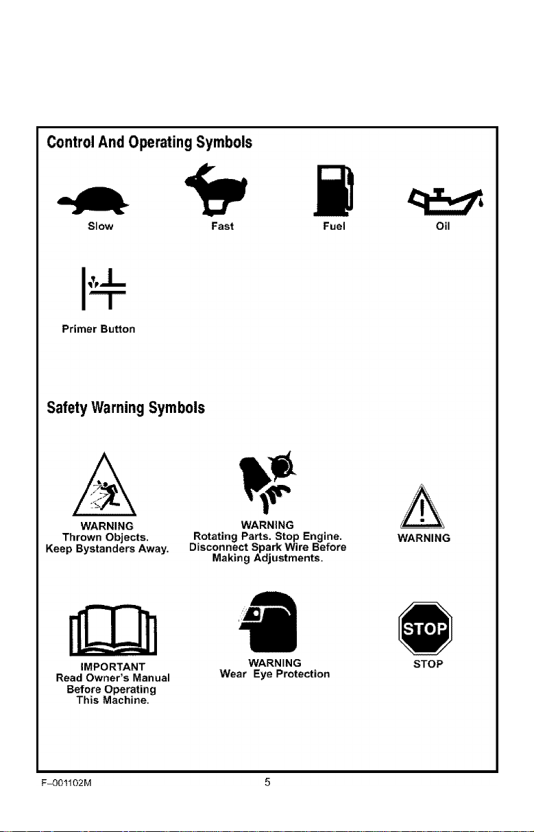
INTERNATIONAL SYMBOLS
IMPORTANT: Many of the following symbols are located on your unit or on literature sup
plied with the product. Before you operate the unit, learn and understand the purpose for
each symbol.
Page 6
ASSEMBLY
Parts Packed Separately In Carton
1 - Owner’s Manual (not shown)
1 - Container Of Oil
1 - Hair Pin
ASSEMBLY
Pi
1 - Hair Pin
' Container of Oil
WARNING: Always wear safety
A
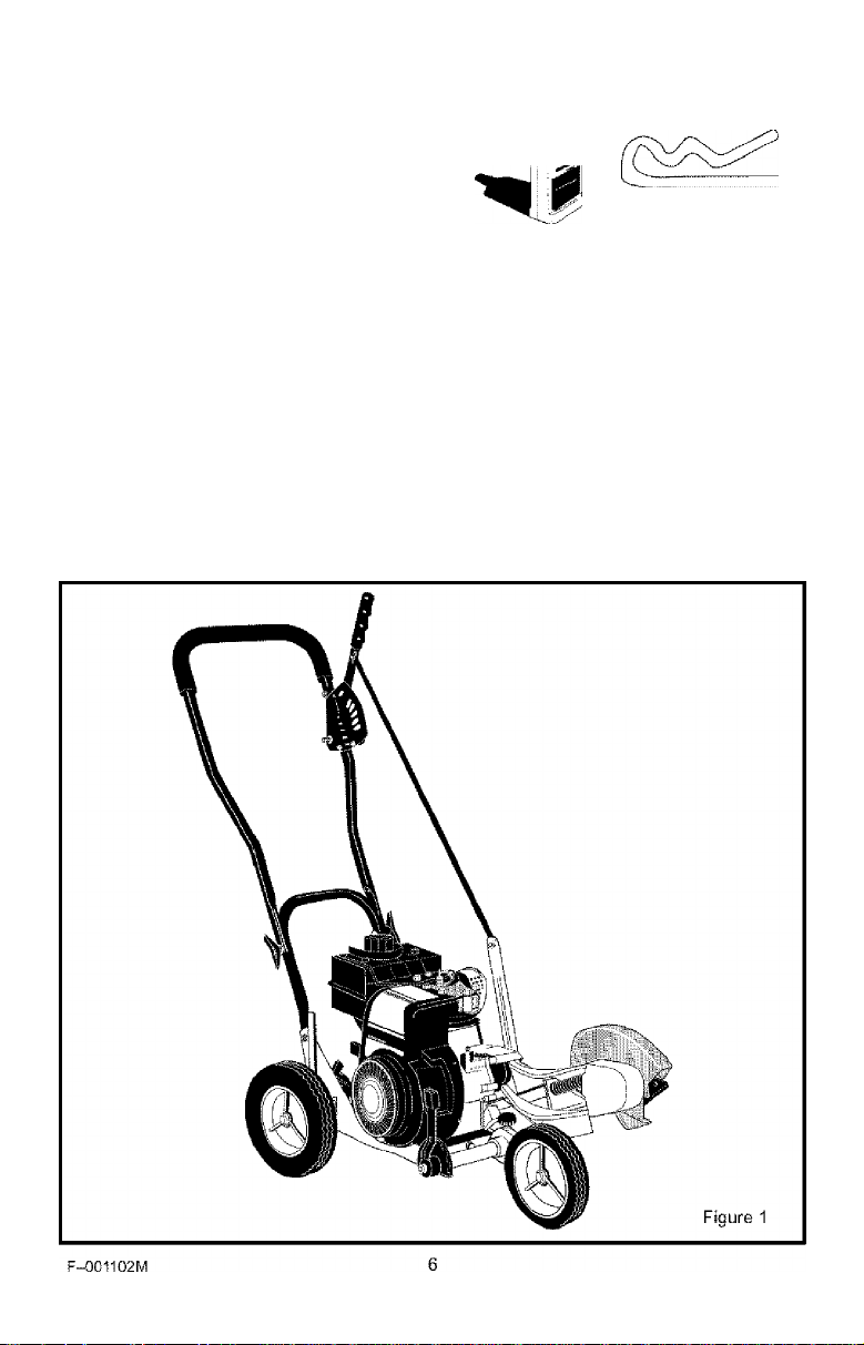
Figure 1 shows the Edger completely as
sembled.
References to the right or left side of the
Edger are from the viewpoint of the opera
tor's position behind the unit.
glasses or eye shields while as
sembling the Edger.
REMOVE THE EDGER FROM THE
CARTON
1. Remove the bottle of oil and parts bag
from the carton.
2. Cut down all four corners of the carton.
3. Remove the packing material positioned
around the unit.
4. Roll the Edger out of the carton and
place on a hard level surface.
Page 7
HOW TO RAISE THE HANDLE
ASSEMBLY
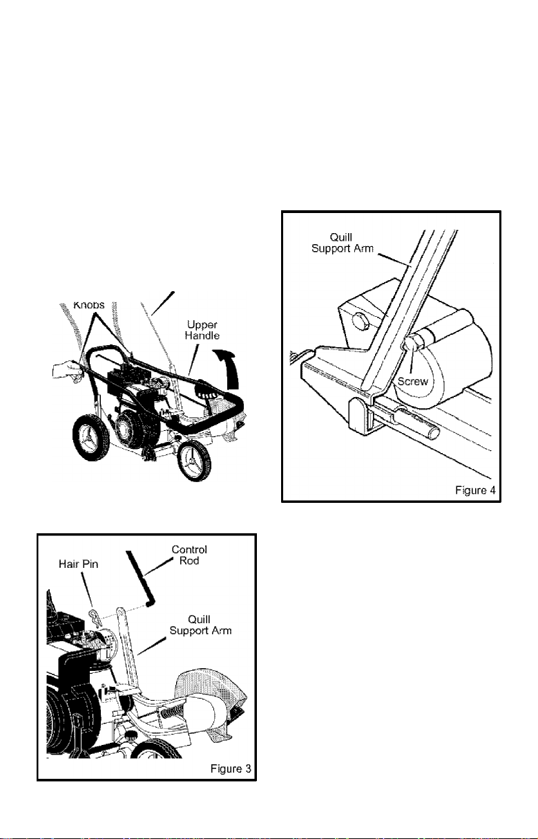
1. Loosen the knobs and raise the upper
handle to the upright position. See
Figure 2. Allow the control rod to swing
freely.
2. Tighten the knobs. Make sure the
knobs are to the outside of the handles
as shown in Figure 2.
* \ Control Rod
I \
Figure 2
3. Insert the end of the control rod from
left to right through the hole in the quill
support arm. Attach with hair pin found
in parts bag. See Figure 3.
4. When the clutch lever is in NEUTRAL
position, the quill support arm must be
close to the screw as shown in Figure 4.
F-001102M
Page 8
ASSEMBLY
HOW TO PREPARE THE ENGINE
Fill With Oil
This Edger was shipped with a 20 ounce
container of SAE30 motor oil. Add this oil to
the engine before operating. To fill the crank
case, remove the oil fill cap/dipstick and add
the SAE30 motor oil. DO NOT OVERFILL.
NOTE: The engine may contain a small
amount of oil. When adding oil, frequently
insert the oil fill cap/dipstick and check
the amount of oil in the engine. DO NOT
OVERFILI.
on Recommendations
Only use high quality detergent oil rated with
API service classification SG. Select the oil's
SAE viscosity grade according to your ex
pected operating temperature. Although mul
ti-viscosity oils {5W30, 10W30, etc.) improve
starting in cold weather, these multi-viscosity
oils will result in increased oil consumption
when used above 32 degrees. Check the
engine oil level more frequently to avoid pos
sible engine damage from running the en
gine low on oil.
32“
Colder
--------
— —
--------
Warmer
<■
-----------------------5W30
------------------------>
SAE30
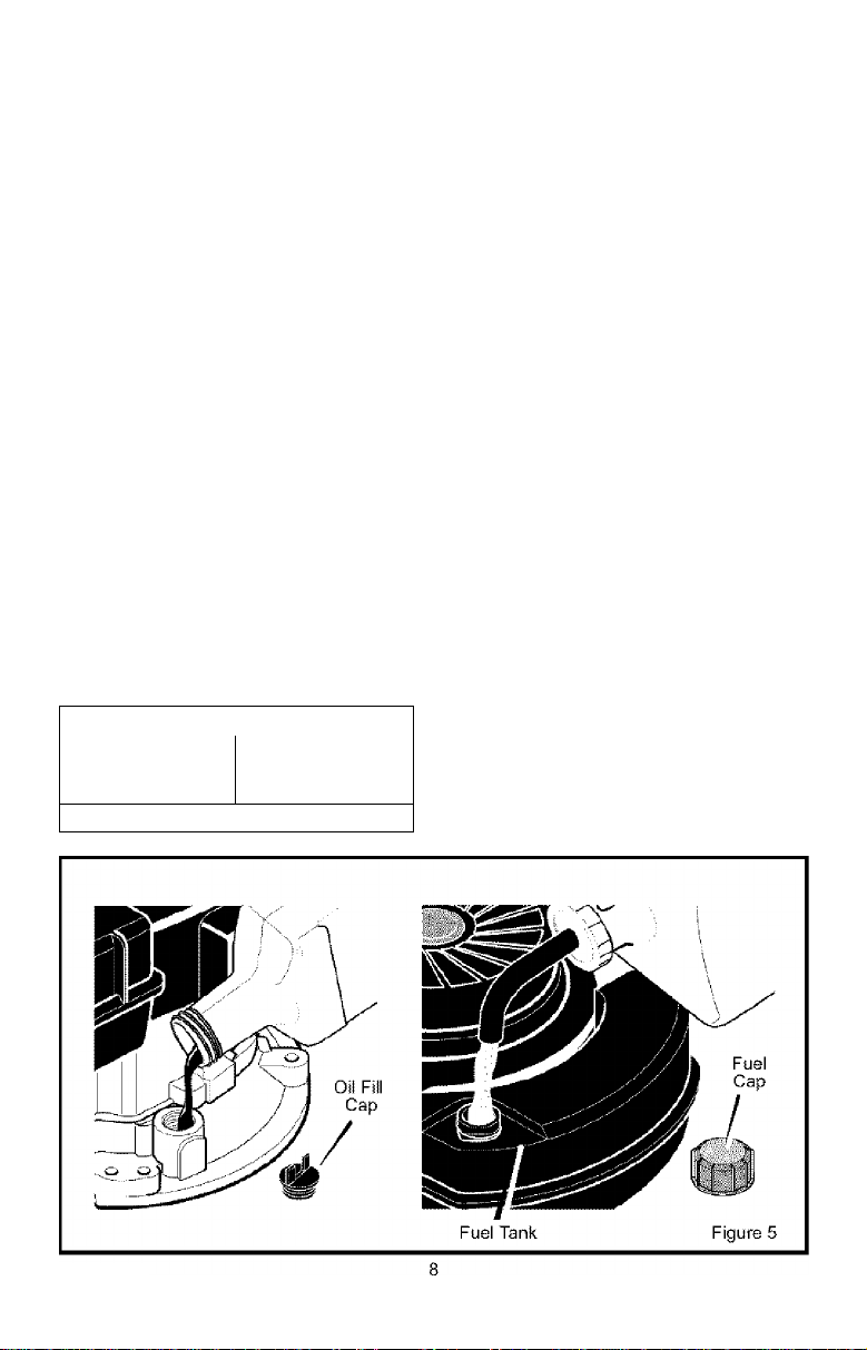
How To Add The Engine Oil
1. Put the Edger on a level surface.
2. Remove the oil fill cap (Figure 5).
3. Slowly fill the engine crankcase. DO NOT
OVERFILL.
How To Fill With Gasoline
Make sure that the gasoline container is
clean and free from dust or other foreign ma
terial. Never use gasoline that could be stale
from long periods of storage.
1. Remove the fuel cap.
2. Fill the fuel tank with clean, fresh, un
leaded grade automotive gasoline.
WARNING: Always use a safety
fuel container. Do not smoke
A
NOTE: ENGINES WHICH ARE CERTIFIED
TO COMPLY WITH CALIFORNIA AND US
EPA EMISSION REGULATIONS FOR
ULGE ENGINES, are certified to operate
on regular unleaded gasoline. Include the
following emission control system(s):
EM, TWC (if so equipped). Include any
user adjustable features - therefore no
other adjustments are needed.
when adding the fuel mixture to
the engine. When inside an enclosure,
do not fill the fuel tank. Before you add
the fuel mixture, stop the engine. Let the
engine cool for several minutes.
F-001102M
Page 9

ASSEMBLY
CHECKLIST
For the best performance and satisfaction
from this quality product, please review the
following checklist before you operate the
Edger;
y All assembly instructions have been
completed.
y Check carton. Make sure no loose
parts remain in the carton.
y Al! fasteners have been properly tight
ened.
As you learn how to use the Edger, pay extra
attention to the following important items:
yy Engine oil is at proper level.
yy Fuel tank is filled with a fresh, dean,
regular Unleaded gasoline.
yy Become familiar and understand the
function of all controls. Before your
start the engine, operate all controls.
IMPORTANT: This unit is equipped with an internal combustion engine and must not be
used on or near any unimproved forest-covered, brush-covered or grass-covered land
unless the engine's exhaust system is equipped with a spark arrester meeting
applicable local or state laws (if any). If a spark arrester is used, it must be maintained in
effective working order by the operator.
In the State of California the above is required by law (Section 4442 of the California
Public Resources Code). Other states may have similar laws. Federal laws apply on fed
eral lands. A spark arrester/muffler is available through your nearest Sears Service Cen
ter (see the REPAIR PARTS section in this manual).
F-001102M
Page 10
OPERATION
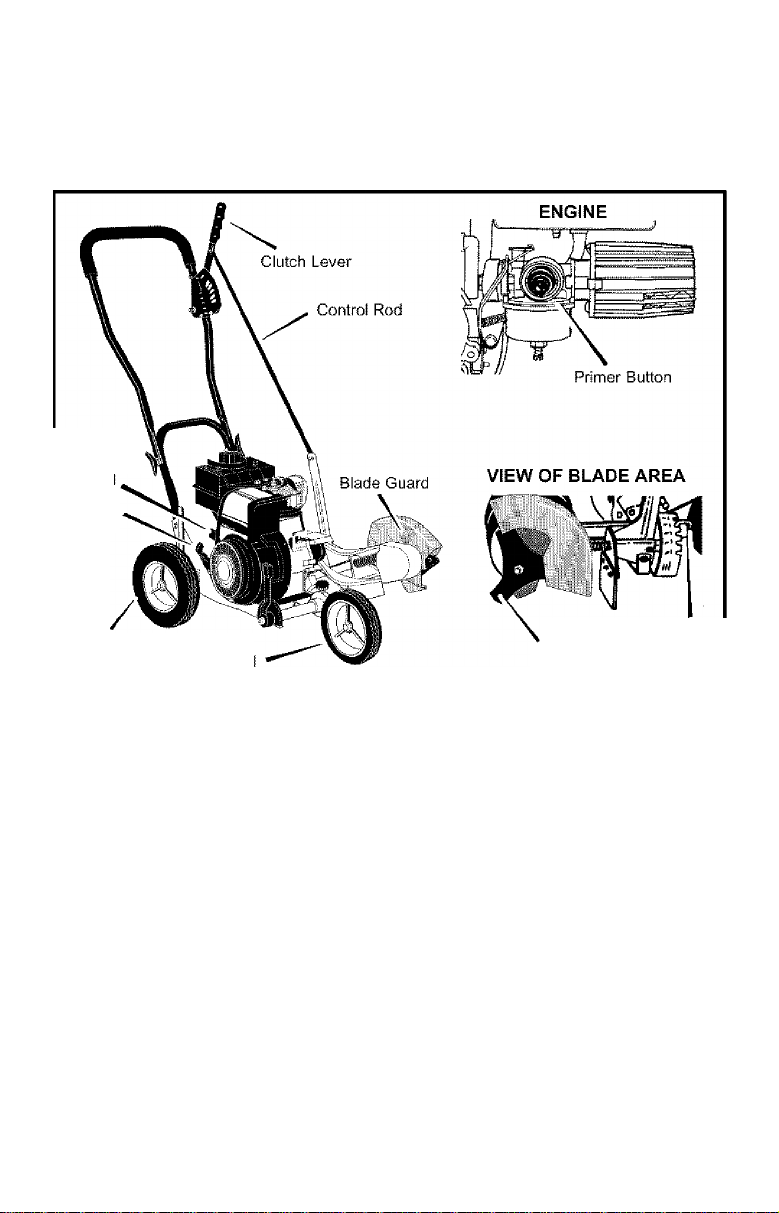
KNOW YOUR EDGER
READ THE OWNER'S MANUAL AND ALL SAFETY RULES BEFORE YOU OPERATE the
Edger. To familiarize yourself with the location of the controls, compare the illustrations with
your Edger. Save this manual for future reference.
Throttle
Contro
Starter
Handle
Adjustable Rear Wheel
Adjustable Front Wheel
Throttle Control - Controls the engine
speed.
Primer Button - Injects fuel directly into
the carburetor for faster starts.
Clutch Lever - Use to start and stop the
blade and control the depth of cut.
Adjustable Rear Wheel - Right rear
wheel is adjustable to level the Edger when
edging along a curb (curb-hopping).
Adjustable Front Wheel - Front wheel
is adjustable from side-to-side for balance.
EYE PROTECTION
Always wear safety glasses. If you wear eye
glasses, put a Wide Vision Safety Mask over
your eye glasses.
F-001102M 10
Index Lever
Blade
The front wheel can also be adjusted down
for curb-hopping ,
Recoil Starter Handle - The engine is
equipped with an easy pull recoil starter.
Blade Guard - Use to prevent stones or
other material from being thrown at the oper
ator.
Index Lever - Permits adjustment from
the edging (vertical) position to the trimming
(horizontal) position. To change position, pull
the index lever and rotate the quill assembly
to the desired angle or position.
WARNING: Debris thrown from
the Edger can result in foreign
A
eyes, which can cause severe eye dam
age. Always wear safety glasses or eye
shields when operating the Edger.
objects being thrown into the
Figure 6
Page 11
OPERATION
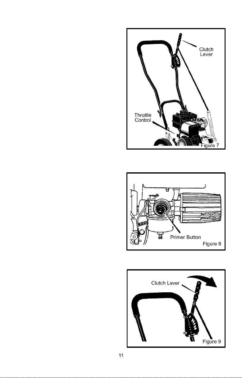
HOW TO STOP THE EDGER
1. Move the clutch lever back to the DIS
ENGAGED position. Then, move the
throttle control to the STOP position.
See Figure 7.
WARNING; Never leave the
EDGER unattended while the
A
engage the cutting blade and stop the
engine.
HOW TO USE
THE THROTTLE CONTROL
1. During normal use, run the engine at full
2. Move the throttie controi up to increase
HOW TO USE
THE PRIMER BUTTON
When starting a cold engine, push the prim
er button five times (see Figure 8). Wait
approximately two seconds between each
push.
IMPORTANT: When starting a warm engine,
do not use the primer button.
engine is running. Always dis
speed.
engine speed, or down to decrease en
gine speed (see Figure 7).
HOW TO USE
THE CLUTCH LEVER
1. start the engine.
2. To engage the cutting blade, move the
clutch lever forward (see Figure 9).
3. Select the edging depth you need. There
are five selections down to approximate
ly 2-3/4 inches deep.
NOTE: For deep edging, first cut at shallow
depths. Then, cut at greater depths until
the desired depth is obtained.
F-001102M
Page 12
OPERATION
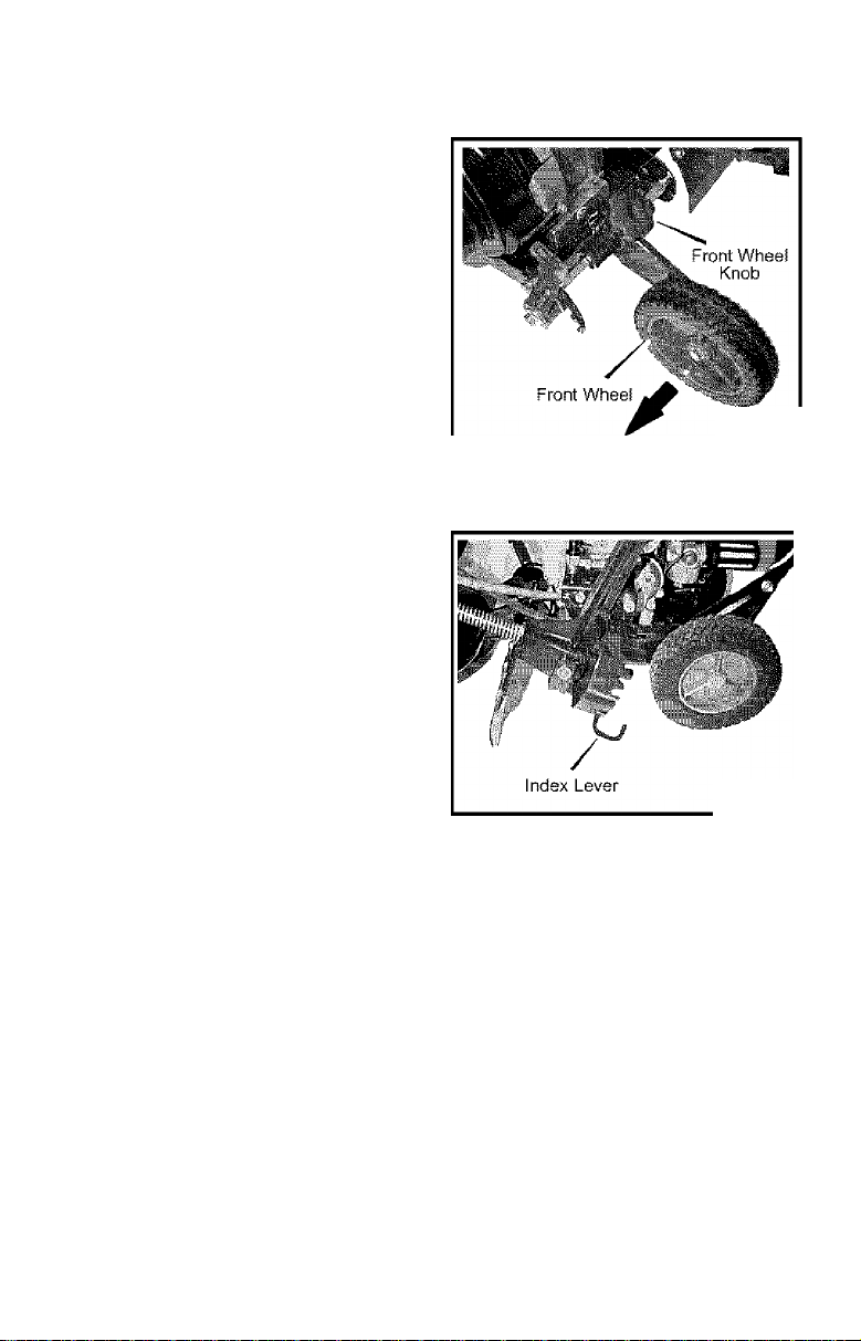
HOW TO USE THE INDEX LEVER
1. stop the engine and disconnect the
spark plug wire from the spark plug.
2. Loosen the front wheel knob shown in
Figure 10. Slide the front wheel all the
way to the right side.
3. Securely tighten the front wheel knob.
NOTE; To prevent the blade from hit
ting the wheel while trimming, make
sure the front wheel is set in the ex
treme right position.
4. Disengage the index lever (see
Figure 11). Move the index lever to the
notch marked 90°.
5. Reconnect the spark plug wire to the
spark plug.
6. Start the engine.
7. Move the clutch lever to the desired trim
ming height.
WARNING; While the engine is
running, never leave the Edger.
A
change the blade position, always dis
engage the cutting blade and stop the
engine.
Before you adjust the wheels or
Figure 10
Figure 11
F-001102M
12
Page 13
OPERATION
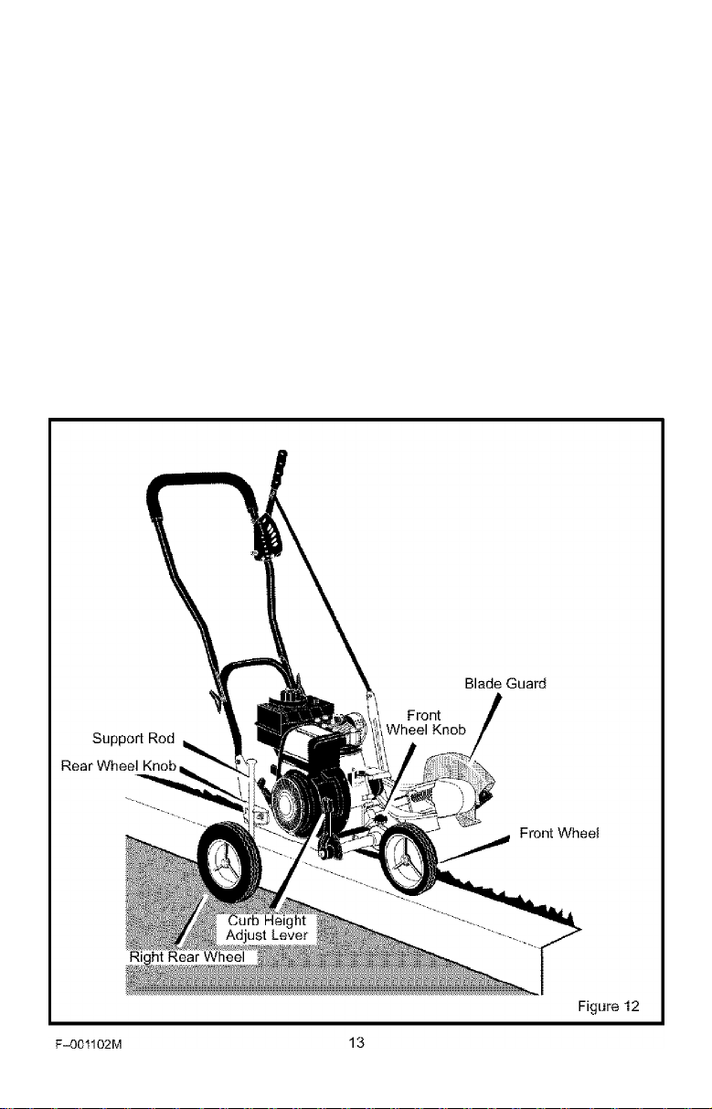
HOW TO USE THE CURB-HOPPING FEATURE
Because the front wheel and the right rear
wheel are adjustable, the Edger can be used
on uneven surfaces, such as the curb shown
in Figure 12. Set the wheel positions as fol
lows.
1. Stop the engine.
2. Disconnect the spark plug wire from the
spark plug.
3. Loosen the front wheel knob.
4. Slide the front wheel to the best posi
tion to clear the curb and balance the
unit.
5. Securely tighten the front wheel knob.
6. Use the curb height adjust lever to
lower the front wheel. Lower the front
wheel until the front wheel is level with
the left rear wheel and the unit is setting
on the curb as shown in Figure 12.
7.
Loosen the rear wheel knob.
8. Lower the right rear wheel until the
Edger is level and the left rear wheel is
on the curb.
9. Securely tighten the rear wheel knob.
10. Connect the spark plug wire to the spark
plug.
WARNING: Keep away from the
A
rotating blade. The blade can
cause injury.
Page 14

OPERATION
HOW TO STOP THE ENGINE
To stop the engine, move the clutch lever all
the way back to the DISENGAGED position.
Then, push the throttle control lever down to
the STOP position.
If the engine will not stop, hold a screwdriver
against the spark plug and against the engine
cooling fins. The spark will go to ground and
the engine will stop.
HOW TO START THE ENGINE
IMPORTANT: Before you start the engine,
operate the controls several times. Make
sure all controls move freely.
1. Check the oil.
2. Fill the fuel tank with regular unleaded
gasoline. Make sure the gasoline is
clean. Leaded gasoline will increase de
posits and shorten the life of the valves.
NOTE: Do not use gasohol or methanol. Do
not use premium unleaded gasoline.
WARNING; Always use a safety
gasoline container. Do not
A
the fuel tank. When inside an enclosure,
do not add gasoline. Before you add
gasoline, stop the engine and let the en
gine cool for several minutes.
3. Make sure the spark plug wire Is con
smoke when adding gasoline to
nected to the spark plug.
4. Pull the clutch lever all the way back to
raise and disengage the blade.
5. Move the throttle control lever to the
FAST position.
6. Some modeis have a primer button on
the front or side of the engine (Figure 13).
Every time you push the primer button,
wait two seconds. For the number of
times required to push the primer but
ton, see the engine manufacturer’s in
structions.
F-001102M 14
Throttle
Control
Primer Button
NOTE: Do not use the primer button to start
a warm engine.
7. To start engine, hoid the recoii starter
handie firmiy with your right hand.
8. Hoid the edger handie firmly with your ieft
hand.
9. Quickly pull the recoil starter handle. DO
NOT allow the starter rope to snap back.
Let the starter rope slowly rewind. If en
gine fails to start after three pulls, push
primer button two times and again pull
the recoil starter handle.
10. When the engine starts, move the throttle
control lever up (FAST position) to in
crease speed or down to decrease
speed. During normal use keep the
throttle in the FAST position.
11. If the engine does not start in 5 or 6 tries,
See the “Problem and Repair” Instruc
tions.
NOTE: The cutting blade speed is con
trolled by the engine speed. To reduce the
cutting blade speed, push down on the
throttle control lever. To Increase the cut
ting blade speed, pull up on the throttle
control lever.
WARNING; Never run the engine
indoors or in a poorly ventilated
A
area. Engine exhaust contains
carbon monoxide, an odorless and
deadly gas. Keep hands, feet, hair and
loose clothing away from any moving
parts. Avoid the muffler and surround
ing areas. Temperatures can exceed 150
degrees.
Figure 13
Page 15

OPERATION
EDGING TIPS
• Edging is best performed when conditions
are dry. If the soil is to wet, dirt becomes
packed around the biade causing prema
ture belt wear and decreased perfor
mance.
• if dirt does become packed around the
blade, stop the engine and remove the
wire from the spark piug. Remove the
packed dirt and debris from the biade.
• For deep edging, first cut at shaiiow
depths. Then, cut at greater depths untii
the desired depth is obtained.
• For uniform edging, make sure the blade
guide rides on the surface.
• Edging can be customized by varying the
number of passes and by the distance the
blade is from the surface.
WARNING: Read the Owner’s
manual. Know location and
A
all safety devices and shields in place.
Never allow children or uninstructed
adults to operate Edger. Shut off engine
before unclogging blade or making re
pairs. Keep bystanders away from ma
chine. Keep away from the blade all ro
tating parts, which cause injury.
functions of all controls. Keep
F-001102M
15
Page 16

MAINTENANCE
CUSTOMER RESPONSIBILITIES
SERVICE
RECORDS
Fill in dates as you
complete regular
service.
Lubricate All Pivot
Points
......................
Lubricate Wheel
Axles
Check Engine Oil . .
Level
.......................
Before
Each
Use Ollen
"V ■■■
Every
10
Hours
V ■
Every
25
Hours
V
Before
Each
Season
Before
Storage
'■V ■
SERVICE
DATES
Change Engine Oil
Replace Air Cleaner.
Filter
.........................
Check Spark Plug
Check Drive Belt
Tighten All Fasteners
Check Blade For ..
Wear Or Damage
Lubricate Ouill Rod/
tube
.......
......
PRODUCT SPECIFICATIONS
Model No.: 536.772400
Date Of Purchase:
Horse Power: 3.5
Displacement: 10cu. in.
Oii Capacity: 20 oz. SAE-30W
Spark Plug:
Spark Plug Gap: 0.030 inch
(163 cc.)
Champion
RJ17LM
■V
V
V V
V ■■■
V
V
..
V
GENERAL RECOMMENDATIONS
The warranty on this Edger does not cover
items that have been subjected to operator
abuse or negligence. To receive full value
from the warranty, the operator must main
tain the Edger as instructed in this manual.
Some adjustments must be made periodical
ly to properly maintain your Edger.
All adjustments in the Service and Adjust
ments section of this manual must be
checked at least once each season.
V
F-001102M
16
Page 17
MAINTENANCE
LUBRICATION
After each 25 hours, appiy a small amount of
engine oil to all moving parts, particularly the
wiheels.
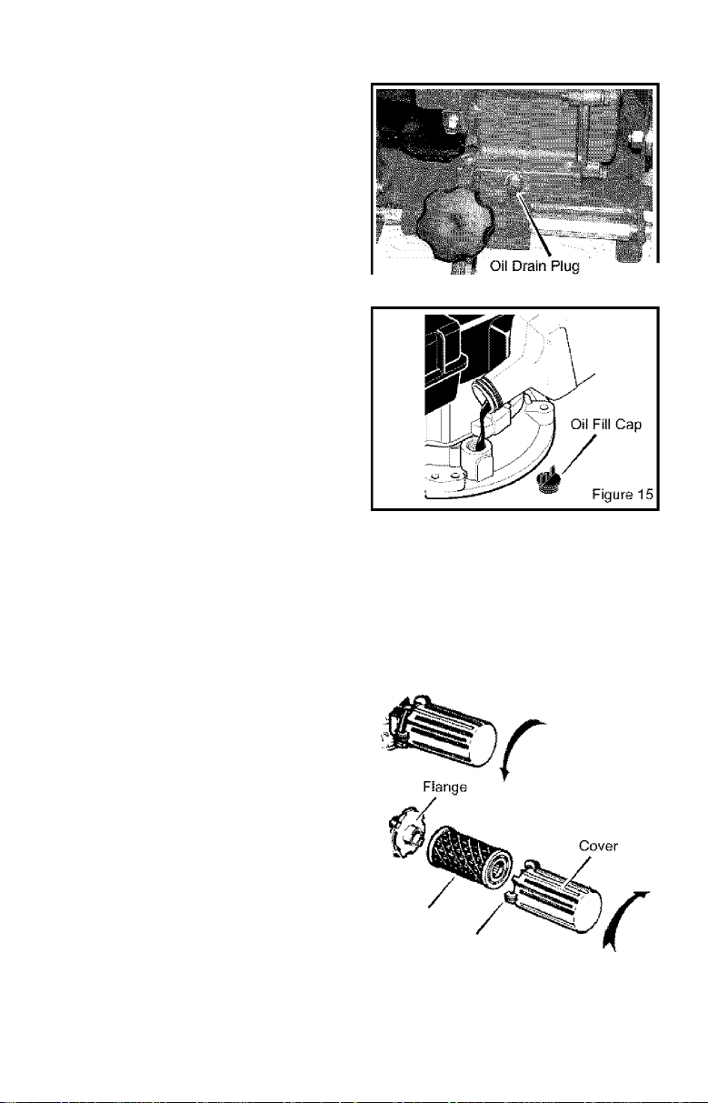
How To Change The Engine Oil
Change the oil in the engine crankcase after
each 25 hours of use.
NOTE; The oil will drain more freely when
the engine is warm.
1. Disconnect the spark plug wire from the
spark plug.
2. Remove the oil drain plug (see
Figure 14). Drain the oil into a flat pan.
3. After draining all the oil, install and tight
en the oil drain plug.
4. Remove the oil fill cap (see Figure 15).
Fill the engine crankcase. Pour slowly.
Do not overfill. See “Product Specifica
tions” for amount and type of oil. Install
the
oil fill cap.
5. Connect the spark plug wire to the spark
plug.
Figure 14
HOW TO CHANGE THE AIR FILTER
Replace the air filter once a year; more often
in dusty or dirty conditions.
NOTE: DO NOT clean or oil the air filter.
The air filter is not serviceable and must
be replaced.
1. Disconnect the spark plug wire from the
spark plug.
2. Turn the cover to the left (counterclock
wise). Remove the cover and the air fil
ter from the flange, (see Figure 16).
3. Discard the air filter.
4. Clean the cover and the flange.
5. Install a new air filter into the cover.
6. Push the cover firmly against the
flange. Turn the cover to the right
(clockwise) until tight. Make sure the re
tainers are locked around the flange.
7. Connect the spark plug wire to the spark
plug.
F-001102M 17
CAUTION: Never run the engine without
the air filter. A defective air filter will
cause a loss of engine power. If dirt or
dust enters the engine through the carbu
retor, the result will be excessive wear or
damage to the engine. Replace a dam
aged or clogged air cleaner immediately.
To Remove,
Turn Counterclockwise
Air Filter
Retainer
To Install,
Turn Clockwise
Figure 16
Page 18
MAINTENANCE
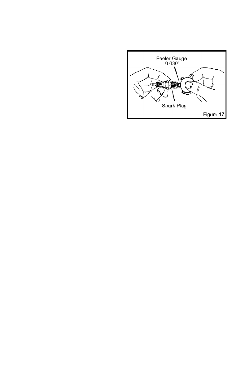
SPARK PLUG
Check the spark plug every 25 hours. Re
place the spark plug if the electrodes are
pitted, burned, or if the porcelain is cracked.
1. Make sure the spark plug is clean.
Clean the spark plug by carefully scrap
ing the electrodes (do not sand blast or
use a wire brush).
2. Check the spark plug gap with a feeler
gauge.
3. Before installing the spark plug, coat
the threads lightly with oil for easy re-
CARBURETOR ADJUSTMENT
Never make unnecessary adjustments to the
carburetor. The carburetor was set at the
factory to operate efficiently under most ap
plications. However, if adjustments are re
quired, we recommend you contact your
nearest Sears Service Center.
WARNING: The engine gover
nor is set at the factory. Do not
A
Over speeding the engine above the fac
tory setting can be dangerous. If you
think the engine governor needs an ad
justment, contact your nearest Sears
Service Center.
change the governor setting.
movai. Tighten the spark plug to a torque
of 15 foot-pounds.
F-001102M
18
Page 19

SERVICE AND ADJUSTMENT
HOW TO REMOVE THE BELT
The belt made of a special compound. !f the
belt becomes worn or breaks, replace the
belt with an original equipment belt.
1. Disconnect the spark plug wire from the
spark plug.
2. Pull the clutch lever back to release the
tension from the belt.
3. Remove the two screws and spacers
from the top of the engine pulley cover.
Remove the engine pulley cover (see
Figure 18),
4. Loosen, do not remove, the screw that
holds the belt guide. Then, move the
belt guide away from the belt.
5. Remove the two screws from the belt
guard (see Figure 19).
6. Remove the old belt from the engine
and quill assembly pulleys. Replace with
an original equipment belt.
7. To install a new belt, reverse the above
steps.
. 'r
© @ ^
rX rV
Spacer
f
^ f
1
Spacer
Engine
' Pulley
Belt
. Screw
Engine
Pulley
Cover
F-001102M
19
Page 20

SERVICE AND ADJUSTMENT
HOW TO REPLACE THE BLADE
The blade is subject to wear and damage,
such as nicks and dents. This will not gener
ally affect its function.
The blade is designed to not require sharp
ening. Do not attempt to sharpen the blade.
The blade is also reversible. If nicks or
dents are excessive, remove the blade and
turn it around. This will provide a fresh cut
ting edge. Replace the blade if both sides
are worn or damaged,
WARNING: Do not sharpen the
blade. Sharpening can damage
A
which can cause injury to yourself or to
others.
To replace the blade, follow the steps below.
the blade and cause it to break,
1. Disconnect the spark plug wire from the
spark plug.
2. Remove the blade locknut that holds
the blade to the drive shaft.
WARNING: To remove or tigh
ten the blade locknut, always
A
Figure 20. Always position the holding
wrench on the nut behind the blade.
3. Remove the blade.
4. Install a new blade and blade locknut.
5. Connect the spark plug wire to the spark
use the method shown in
Tighten the blade locknut to a torque of
40-45 foot pounds.
plug.
Page 21

SERVICE AND ADJUSTMENT
STORAGE
WARNING: Never store the
Edger indoors with fuel in the
A
ciosed, pooriy ventilated area where
fumes could reach an open flame, a
spark or a pilot light as on a furnace, wa
ter heater or clothes dryer.
A
Gasoline fumes can cause an explosion
or a fire.
When the Edger is put in storage for thirty
days or more, follow the steps below to
make sure the Edger is in good condition the
following season.
Edger
• Completely clean the Edger.
• Check the Edger for worn or damaged
• Apply a small amount of engine oil to all
• Put the Edger in a building that has good
• Cover the Edger with a suitable protec
IMPORTANT: Never cover the Edger while
the engine and exhaust areas are still
warm.
NOTE: A yearly checkup or tune-up by a
Sears Service Center is a good way to
make sure that your Edger will provide
maximum performance for the next sea
son.
Engine
IMPORTANT: It is important to prevent
gum deposits from forming in fuel system
fuel tank. Never store in an en-
WARNING: Do not remove gas
oline while inside a building,
near a fire, or while you smoke.
parts. Tighten all loose hardware.
moving parts, particularly the wheels.
ventilation.
tive cover that does not retain moisture.
Do not use plastic.
parts such as the carburetor, fuel filter,
fuel hose, and tank during storage. Also,
using alcohol-blended fuels (called gasohol, ethanol or methanol) can attract
moisture which leads to separation and
formation of acids during storage. Acidic
gas can damage the fuel system of an en
gine while in storage.
To prevent engine damage when the Edger
is in storage for 30 days or more, follow the
steps below;
• Let the engine run until it is out of gaso
line.
• If you do not want to remove the gaso
line, add a fuel stabilizer to any gasoline
left in the fuel tank. A fuel stabilizer will
minimize gum deposits and adds. If the
fuel tank is almost empty, mix the fuel
stabilizer with fresh gasoline in a sepa
rate container and add the mixture to the
fuel tank. Always follow the instructions
on the stabilizer container. Start the en
gine. Let the engine run for 10 minutes
to allow the mixture to reach the carbu
retor.
• Change the engine oil. See “How To
Change The Engine Oil” in the Mainte
nance section.
• Lubricate the piston/cylinder area. This
can be done by first removing the spark
plug and squirting a small amount of
clean engine oil into the spark plug hole.
Then, cover the spark plug hole with a
rag to absorb oil spray. Next, rotate the
engine by pulling the starter two or three
times. Finally, Install the spark plug and
attach the spark plug wire.
• Store the Edger in the operating position
with the wheels down. If the Edger Is
stored in any other position, oil from the
crankcase will enter the cylinder and
cause a service problem.
F-001102M
21
Page 22

TROUBLE SHOOTING CHART
TROUBLE CAUSE CORRECTION
Engine difficult to start
stale fuel Drain fuel tank. Fill with fresh
fuel.
or
Clogged fuel filter Replace fuel filter
Dirt in fuel tank or out of fuel Clean fuel tank.
Engine runs erraticaiiy
Carburetor out of adjustment Take unit to a Sears Service
Center.
or
Fouled spark plug Clean and set spark plug
gap.
Engine wiii not run at fuii
speed
Engine smokes
excessively
Dirty air filter Replace air filter.
Plugged air filter Replace air filter.
Debris interfering with blade Clean debris from blade.
Cutting biade will not
rotate
Loose blade Tighten blade nut.
Defective V-belt Replace V-belt.
Defective quill bearings Replace the quill assembly.
Blade will not cut properly
Damage or worn blade Reverse the blade or replace
the blade.
Excessive vibration Loose parts Stop engine immediately.
Tighten all fasteners. If
vibration continues, take the
unit to a Sears Service
Center.
F-001102M
22
Page 23

CRAFTSMAN 536.772301
REPAIR PARTS
43
44
KEY
DESCRIPTION
NO.
4 HP 143.004001
10
(See Engine pages)
12
Screw, 3/8-16x1.00
Pulley, Hall
20
22
Screw, 5/16-24x1.00
24
Washer
Flatwasher
26
Belt
29
30
Screw 5/16-24x1.00
Flat washer
31
32
Guide, Belt
F-001102M
PART NO.
Engine
47792
314781
181608
120638
45602
32668
578733
45602
51600
KEY
NO. DESCRIPTION
40 Cover, Engine Pulley
41 Screw, 5/16-24x3.00
42 Spacer, Sleeve
43 Screw, 5/16-24x3.75
44 Spacer
45 Spacer, Sleeve
80 Assembly, Frame
81 Strap
Instruction Manual
ENG/SP
23
323095 F
PART NO.
331281-848
181624
315095
173030
308237
315095
323534-848
308154-848
F-001102M
Page 24

CRAFTSMAN 536.772301 REPAIR PARTS
F-001102M
KEY
DESCRIPTION
NO.
1
Blade Guard
2
Bolt, Carriage
4
Nut, 5/16-18 710205
Guide, Belt Front
5
6
Screw,
1/4-20X.50
Cover, Quill Pulley
8
9
Screw,
10-16X.50
Decal, Blade Guard
24
PART NO.
331076-848
57072
326748-848
710264
53405-848
710271
333874
Page 25

CRAFTSMAN 536.772301 REPAIR PARTS
REF.
FRAME ASSEMBLY
KEY
DESCRIPTION
NO.
Front Wheel Arm
150
Front Curb Hopper 740132
151
PART NO.
339299-848
152 Pushnut, Washer 338614
Plastic Washer 325892
153
154 Spacer, Height Adjust 331421
Pin, Spring 332002
155
Lever, Height Adjust
156
F-001102M
331419
331765 E
KEY
NO.
DESCRIPTION
PART NO.
157 Knob, Rectangle 20252
Flatwasher
158
Nut
159
Screw, 5/16-18X.63
160
Plate, Height Adjust
161
Knob, Molded
163
164
Nut, 5/16-18 710205
22265
45905
51333
331394-848
339388
25
Page 26

CRAFTSMAN 536.772301 REPAIR PARTS
184
KEY
DESCRIPTION
NO.
Bracket, Curb Hop Mnt 6842 182 Spacer, Sleeve 45222
170
171
Screw, 5/16-18X.75
172
Nut, 5/16-18
PART NO.
180077
1498
180 Bolt, 5/16-18x2.00 126380 186
Clevis 8082
181
F-001102M
26
KEY
DESCRIPTION
NO.
Flalwasher
183
184
Knob, Wing 5/16-18
Rod, Wheel Support
PART NO.
120393
671294
310896
Page 27

CRAFTSMAN 536.772301 REPAIR PARTS
305
KEY
DESCRIPTION PART NO.
NO.
Flatwasher
300
Quill Support
301
302
Bolt, 3/8-16
Flatwasher
303
REF.
FRAME ASSY.
KEY
NO.
120396
338656-848
308254
321 Quill Assembly
322 Lever, Index
323
710083 325 Nut, 5/16-18 1498
305 Nut, 3/8-16 1499 329
Rubber Deflector
310
311 Screw, 10-16x1.50
Spring
320
F-001102M
308243 330
710271
331 Nut, 1/2-20 46023
51603
27
323129 E
DESCRIPTION PART NO.
338070
308466
Spring, Torsion
Flatwasher
Blade, Edger
308155
22265
740296
Page 28

CRAFTSMAN 536.772301 REPAIR PARTS
KEY
DESCRIPTION PART NO.
NO.
424
Bolt, 5/16-18x1.75 315288
Knob, Wing 5/16-18 671294
425
Lower Handle
720
721
Nut, 5/16-18
F-001102M
KEY
NO.
722
750 Control Rod 580292-853
740127-853 751
1498
754 Hair Pin
28
DESCRIPTION PART NO.
Screw, 5/16-18x.63 51333
Half Pin
36368
36368
Page 29

CRAFTSMAN 536.772301 REPAIR PARTS
I
745
KEY
DESCRIPTION PART NO.
NO.
Upper Handle 740147
725
Selector Plate
731
732
Screw, 1/4-20x1.25
310052-853 740 Nut, 5/16-18 1498
180024 741 Grip, Hand 56924
KEY
NO.
739
735 Nut, 1/4-20 782585 743
737 Depth Adjust Handle
738 Screw, 5/16-18x1.25
F-001102M
310050-853 745 Nut, 3/8-16 1499
180081
29
323136 F
DESCRIPTION
PART NO.
Spring, Compression 25644
Stud
310053
Page 30

CRAFTSMAN 536.772301
REPAIR PARTS
105
108
109
KEY
DESCRIPTION
N0.
PART NO.
103 Nut, 3/8-16 1499
Spacer, Sleeve
105
Bolt, HHSH 3/8
106
Tire & Rinrr
108
310715 113
310716
336545 116
109 Screw, 5/16-18x3.00 180113
Flatwasher
110
F-001102M
120393 118
114
KEY
DESCRIPTION
NO.
Ill
Nut, 5/16-18 710205
Spacer, Sleeve 51887
114 Tire & Rim
Tire & Rim
117 Flatwasher
Colter Pin 121222
30
343720 B
PART NO.
336546
336545
17X91
Page 31

CRAFTSMAN 143.004001 REPAIR PARTS
KEY PART
NO. DESCRlPTiON
NO.
0 640172 Carburetor {Incl. 184 of Engine Parts
1 631615 Throttle Shaft & Lever Assembly
2 631767 Throttle Return Spring
4 631184 Dust Seal Washer
5 631183 Dust Seal (Throttle)
6 631036 Throttle Shutter
7 650506 Shutter Screw
16 632164 Fuel Fitting
17 651025 Throttle Crack Screw/ldle Speed
18 630766 Tension Spring
20 640018 Idle Restrictor Screw
20A 640053 Idle Restrictor Screw Cap
25 631867 Float Bowl
27 631024 Float Shaft
28 632019 Float
29 631028 Float Bowl ”0” Ring
30 631021 Inlet Needle, Seat, & Clip (Incl. 31)
31 631022 Spring Clip
35 36045A Primer Bulb/Retainer Ring
36 640019 Main Nozzle Tube
37 632547 ”0” Ring, Main Nozzle Tube
40 640074 High Speed Bowl Nut
44 27110A Bowl Nut Washer
47 630748 Welch Plug, Idle Mixture Well
48 631027 Welch Plug, Atmospheric Vent
60 632760 Repair kit (Incl. Items Marked PK in
List)
Screw
Notes)
(
Carburetor No. 640172
F-001102M
31
Page 32

CRAFTSMAN 143.004001 REPAIR PARTS
^^301
J^300
\
■
{'
9CO
F-001102M
■'262
32
Page 33

CRAFTSMAN 143.004001 REPAIR PARTS
KEY PART KEY PART
NO. DESCRlPTiON
NO.
1 36560 Cylinder 80 30574A Governor Shaft
2 26727 Dowel Pin
14 28277 Washer
15 31334 Governor Rod 83 30588A Governor Spool
16 31336 Governor Lever 86 650488 Screw, 1/4-20 x 1-1/4”
17 31335 Governor Lever Clamp 89 610961 Flywheel Key
18 651018 Screw 90 611195 Flywheel
19 34593 Extension Spring 92 650815 Belleville Washer
20 32600 Oi! Seal 93 650816 Flywheel Nut
25 36552 Blower Housing Baffle 100 34443A Solid State Ignition
25A 35883 Baffle Extension
26 650802 Screw, 1/4-20 x 5/8”
26A 650926 Screw, 8-32 x 21/64”
30 37336 Crankshaft
40 40020 Piston, Pin & Ring Set
40 40021 Piston, Pin & Ring Set
41 40018
41 40019
42 40022 Ring Set (Std.)
42 40023 Ring Set (.010" OS) 130 650694A Screw, 5/16-18x2”
43 20381 Piston Pin Retaining Ring 130A 6021A Screw, 5/16-18 X 1-1/2”
45 30963B Connecting Rod Ass'y. 132 650708 Washer
46 3261OA Connecting Rod Bolt
48 27241 Valve Lifter 150 31672 Valve Spring
49 28594 Oi! Dipper 151 31673 Valve Spring Cap
50 32197A Camshaft (MCR) 151A 40016A Valve Seal
60 29745 Blower Housing Extension 169 27234A Valve Cover Gasket
65 650123 Screw, 10-24 x 1/2” 170 27666 Breather Body
69 27677A Cylinder Cover Gasket 171 31410 Breather Element
70 35863A Cylinder Cover 172 34146 Valve Cover
72 27642 Oil Drain Plug
75 26208 Oil Seal
(Ind. 2, 20, 72 & 125)
(Incl. 262)
(Std.)
(.010" OS)
Piston & Pin Ass'y. (Std.) (Incl. 151)
(Incl. 43)
Piston & Pin Ass'y. (Incl. 151)
(.010" OS) (Incl. 43)
(Incl. 46 & 49)
(Incl. 75 thru 83,311)
N0.
81 30590A Washer
82 30591 Governor Gear Ass'y.
102 651024 Solid State Mounting Stud
103 651007 Screw
110 35182 Ground Wire
119 36437 Cylinder Head Gasket
120 36438 Cylinder Head
125 36471 Exhaust Valve (Std.)
125 36472 Exhaust Valve (1/32” OS)
126 29314C Intake Valve (Std.)
126 29315C Intake Valve (Std.)
135 33636 Resistor Spark Plug
173 32447 Breather Tube
173A 32446 Breather Tube Grommet
NO. DESCRIPTION
(Inc!. 81)
(Incl. 119 & 130)
(Incl. 151)
(Inc!. 151)
(RJ17LM)
F-001102M
33
Page 34

CRAFTSMAN 143.004001 REPAIR PARTS
174 650783 Screw, 10-24 x 3/4” 290 29774 Fuel Line
178 29752 Nut & Lock Washer 292 26460 Fuel Line Clamp
179 30593 Retainer Clip 298 650665 Screw, 1/4-15x3/4”
182 6201 Screw, 1/4-28 x 7/8” 300 35591 Fuel Tank
184 26756 Carburetor To Intake Pipe
185 36703
186 31341 Governor Link
200 36677 Control Bracket
203 31342 Compression Spring
204 651029 Screw, T-10, 5-40 x 7/16”
206 610973 Terminal
215 32410 Control Knob
223 650451 Screw, 1/4-20 x 1"
224 26754A Intake Pipe Gasket
238 650932 Screw, 10-32 X 49/64”
239 34338 Air Cleaner Gasket
241 35797 Air Cleaner Collar
245 35066 Air Cleaner (Conical)
250 35065 Air Cleaner Cover
260 35585 Blower Housing
262 650737 Screw, 1/4-20 x 1/2”
275 40000A Muffler (W/Catalyst)
277 650988 Screw, 1/4-20 x 2-5/16”
285 36467A Starter Cup
287 650926 Screw, 8-32 x 21/64”
Gasket
Intake Pipe
(Incl. 182,184, 224)
(Incl. 203 thru 209A)
301 36246 Fuel Cap (Black)
305 35554 Oil Fill Tube
307 35499 “O” Ring
308 35539 Fill Tube Clip
310 35556 Dipstick
313 34080 Spacer
339 28212 Spacer
340 35926 Fuel Tank Bracket
342 650751 Screw, 1/4-20 x 7/16”
345 32664 Baffle Heat
370A 36261 Lubrication Decal
370B 35703 Throttle Decal
370C 37199 Primer Decal
370K 36695 Starter Decal
380 640172 Carburetor (Incl. 184)
390 590732 Recoil Starter
400 36439 Gasket Set (Incl. Items
416 36085 Spark Arrestor Kit
417 650821 Screw, (Optional)
(Incl. 292 & 301)
(NOTE; This engine could
have been built with
590738 starter).
Marked PK in Notes)
(Incl. 417) (Optional)
F-001102M
34
Page 35

CRAFTSMAN 143.004001 REPAIR PARTS
starter No. 590732
1-11
w
— 2
<a>—
F-001102M
r
...
1
KEY
N0.
0 590732 Rewind Starter
1 590599A Spring Pin (inci. 4)
2 590600 Washer
3 590696 Retainer
4 590601 Washer
5 590697 Brake Spring
6 590698 Starter Dog
7 590699 Dog Spring
8 590700 Pulley & Rewind Spring Ass'y.
11 590695 Starter Housing Ass’y. (40 degree grommet)
12 590535 Starter Rope (Length 98” x 9/64” dia.)
13 590701 Starter Handie
PART
NO. DESCRIPTION
35
Page 36

CRAFTSMAN 143.004001 REPAIR PARTS
starter No. 590738 (optional)
-14
F-001102M
KEY
NO.
0 590738 Rewind Starter
3 590740 Retainer
6 590616 Starter Dog
7 590617 Dog Spring
8 590618A Pulley & Rewind Spring Ass'y.
11 590687A Starter Housing Ass’y. (40 degree grommet)
12 590535 Starter Rope (Length 98” x 9/64” dia.)
13 590701 Starter Handle
14 590760 Spring Clip
PART
NO. DESCRIPTION
36
Page 37

CONTENIDO
GARANTÍA 37 TABLA DE LOCALIZACiON DE
SÍMBOLOS INTERNACIONALES 40
MONTAJE 41
OPERACION 45
MANTENIMIENTO 51
SERVICiO Y AJUSTES 54 CONTRACUBIERTA
AVERIAS 57
PIEZAS DE REPUESTO 21
PIEZAS DE REPUESTO (MOTOR)
PEDIDOS / SERVICIO
25
GARANTÍA
GARANTÍA LiMITADA DE DOS ANOS PARA LA ORILLADORA CRAFTSMAN
Esta orilladora Craftsman está garantizada por dos años a partir de la fecha de compra, siem
pre y cuando, se le haya dado mantenimiento, lubricación y afinado de acuerdo con las Ins
trucciones de operación y mantenimiento que aparecen en el manual del usuario, Craftsman
reparará, sin costo alguno, cualquier defecto en el material y/o mano de obra de la unidad.
Si esta orilladora Craftsman se utiliza para propósitos comerciales o de arrendamiento, la ga
rantía será válida por sólo 90 días a partir de la fecha de compra.
Esta garantía no cubre lo siguiente:
• Piezas reemplazables que se desgasten durante el uso normal, por ejemplo: bujías, etc.
• Reparaciones necesarias debido al abuso o negligencia por parte del operador de la uni
dad, incluyendo cigüeñales torcidos, y por no mantener la unidad de acuerdo con las ins
trucciones que aparecen en el manual del usuario.
EN LOS ESTADOS UNIDOS, EL SERVICIO BAJO GARANTÍA PARA LA ORILLADORA
CRAFTSMAN ESTÁ DISPONIBLE EN EL CENTRO / DEPARTAMENTO DE SERVICIO DE
SEARS MÁS CERCANO. ESTA GARANTÍA ES VÁLIDA SOLAMENTE SI EL PRODUCTO
SE USA EN LOS ESTADOS UNIDOS.
Esta garantía le brinda derechos legales específicas, además, usted puede tener otros dere
chos legales que varían según el estado donde resida.
Sears, Roebuck and Co., D817WA, Hoffman Estates, IL 60179
A
Las emisiones generadas por el motor, algunos de sus compuestos
y ciertos componentes del vehículo contienen o emiten vapores
químicos reconocidos en el Estado de California como carcinóge
nos, y pueden causar malformaciones congénitas y otros proble
mas reproductivos.
Los bornes, conectores y accesorios relacionados con la batería
contienen plomo y compuestos del plomo. Estos químicos están
reconocidos por el Estado de California como carcinógenos, rela
cionados además con malformaciones congénitas y otros proble
mas reproductivos. DEBE LAVARSE BIEN LAS MANOS DESPUÉS
DE TOCARLOS.
F-001102M
ADVERTENCIA
37
A
Page 38

NORMAS DE SEGURIDAD
Prácticas de seguridad para la operación de la orilladora.
ADVERTENCIA; Busque este símbolo que le indicará puntos importantes
A
A
porte, ajuste o reparación, desconecte
siempre el cable de la bujía y colóquelo
alejado de ésta.
Pasos preliminares
• Lea detenidamente el Manual dei usuario.
controles y e! uso correcto de la orilladora.
Aprenda cómo apagar, detener y desen
ganchar los controles de la orilladora, en
caso de que tenga que hacerlo rápidamen
te.
• Siempre que use la orilladora deberá ves
tirse con ropa apropiada y usar zapatos
que le protejan y le den buena tracción.
• Mantenga el área de operación despejada
de personas, especialmente de niños pe
queños y mascotas.
• Examine ei área en donde va a ser usada
la orilladora y despéjela de cualquier objeto
que pudiera ser lanzado por la máquina.
Combustible
• Tenga mucho cuidado a! manejar gasolina
y otros combustibles, estos son sumamen
te inflamables. ,
• Use únicamente recipientes aprobados.
• Revise e! nivel de combustible cada vez
que use la orilladora. Asegúrese de dejar
suficiente espacio, ya que el calor de! mo
tor y/o del sol puede causar la expansión
del combustible. '
• Debe reabastecer o llenar el tanque de
combustible en un área abierta y con mu
cho cuidado. Nunca ilene e! tanque en un
espacio cerrado. Fije bien la tapa del tan- ‘
que de combustible y limpie cualquier de
rrame. I
• Nunca quite la tapa del tanque de combus
tible ni añada combustible al tanque cuan- <
do el motor esté caliente o en marcha.
F-001102M 38
de precaución para su seguridad. Este símbolo quiere decir: “¡Atención!
¡Esté alerta! Su seguridad está en peiigro”.
ADVERTENCIA; Para prevenir
el arranque accidental de la má
quina durante el montaje, trans
Debe familiarizarse completamente con los
• Nunca guarde la orilladora llena de com
bustible ni e! recipiente de combustible en
un recinto donde haya alguna llama ex
puesta.
Operación
• Nunca permita que niños o adolescentes
manejen la orilladora. Manténgalos fuera
del área de recorte. Nunca permita que
usen la unidad los adultos no familiariza
dos con las instrucciones de operación.
• No opere la orilladora si está tomando al
gún fármaco u otra medicina que le provo
que somnolencia o que afecte su habilidad
de operar esta unidad con seguridad.
• No use la orilladora si no está física o men
talmente capacitado para hacerlo de ma
nera segura.
• Siempre use gafas de seguridad o caretas
protectoras al operar, ajustare reparar la
orilladora, esto protegerá sus ojos de obje
tos que pudieran ser lanzados por la uni
dad.
• No ponga las manos o los pies cerca o de
bajo de piezas giratorias.
• Preste mucha atención cuando maneje la
orilladora cerca de la calle, o cuando cruce
por calzadas, calles o caminos de grava.
Esté alerta tanto al tráfico como a proble
mas potenciales o imprevistos.
• Tenga cuidado para evitar caldas o resba
lones.
• Nunca opere la orilladora sin colocar en su
lugar los respectivos resguardos u otros
aditamentos diseñados para su protección
y seguridad.
• Nunca opere la orilladora a alta velocidad
en superficies resbalosas. Siempre que
retroceda mire hacia atrás y hágalo con
cuidado.
• Nunca permita que haya personas cerca
de la orilladora.
• Mantenga alejados a niños y mascotas du
rante la operación de la máquina.
• Siempre opere el equipo a la luz del día o
con buena iluminación artificial.
Page 39

Nunca ponga en marcha un motor dentro
NORMAS DE SEGURIDAD
de un recinto o de un área cerrada. Los
vapores del escape son peligrosos, ya que
contienen MONÓXIDO DE CARBONO,
UN GAS INODORO Y MORTAL.
Tome todas las precauciones necesarias
cuando deje la orilladora desatendida.
Apague el motor.
No sobrecargue la capacidad de su orilladora a! tratar de rebordear a una profundi
dad o a una velocidad excesiva.
Almacenamiento
• Cuando la orilladora va a ser almacenada
por un período largo de tiempo, consulte
las instrucciones del manual del usuario
para obtener detalles importantes al res
pecto.
• Nunca almacene la orilladora con combus
tible en el tanque, dentro de un recinto
donde pudieran haber fuentes de ignición
tales como calentadores de agua, estufas
secadoras de ropa y otras fuentes pareci
das. Permita que el motor se enfríe antes
de guardar la unidad en un recinto cerrado.
• Mantenga la orilladora en condiciones de
funcionamiento seguras. Revise con regu
laridad todos los sujetadores para mante
nerlos debidamente apretados.
Reparación / Ajustes
• Si golpea un objeto extraño con la unidad,
apague el motor. Desconecte el cable de la
bujía y manténgalo alejado de ésta para
evitar un arranque accidental del motor.
Inspeccione la orilladora para ver si ésta
sufrió algún daño. Si está averiada, deberá
repararla antes de hacerla funcionar nue
vamente.
• Si la orilladora comienza a vibrar excesiva
o anormalmente, apague el motor. Revise
la unidad de inmediato para determinar la
causa. Generalmente ia vibración suele
indicar que existe alguna avería.
• Apague el motor siempre que tenga que
dejar el equipo. Desconecte el cable de la
bujía antes de destapar la cuchilla y antes
de realizar cualquier reparación, ajuste o
inspección a la unidad.
• Antes de limpiar, reparar o inspeccionar la
unidad, apague el motor y asegúrese de
que todas las partes en movimiento se ha
yan detenido.
• Nunca haga ajustes o reparaciones mien
tras el motor esté en marcha, a menos que
el fabricante lo indique específicamente.
F-001102M
39
Page 40

NORMAS DE SEGURIDAD
SÍMBOLOS INTERNACIONALES
IMPORTANTE: La mayoría de los símbolos siguientes se encuentran en ia unidad o en la
información que viene con el producto. Antes de usar la unidad, familiarícese con el signifi
cado de cada uno de ios símbolos.
Símbolos de control y funcionamiento
i
Marcha lenta Marcha rápida
Botón cebador
Símbolos de advertencia de seguridad
Combustible
Aceite
ADVERTENCIA
Lanza objetos. Mante
nerse alejado de
transeúntes.
IMPORTANTE
Lea el Manual del
usuario antes de
operar esta unidad.
F^01102M
ADVERTENCIA
Piezas giratorias. Apagar el
motor y desconectar el cable
de la bujía antes de hacer
cualquier ajuste a la unidad.
m
ADVERTENCIA
Usar protección para
los ojos
40
ADVERTENCIA
PARAR
Page 41

ENSAMBLAJE
MONTAJE
Contenido de la boisa de parties
1 - Manuaí de] usuario (no aparece en la
figura)
1 - Botella de aceite
1 - Horquilla
A
1 - Horquilla
1 - Botella de aceite
ADVERTENCIA: Siempre use
gafas / anteojos de seguridad
A
orí Madera.
La Figura 21 muestra la orllladora completa
mente ensamblada.
Cuando se indica el lado izquierdo o dere
cho de la orüiadora en este manual, siempre
se hace desde el punto de vista del operador
en su posición detrás de la unidad.
cuando esté ensamblando la
INSTRUCCIONES PARA SACAR
LA ORILLADORA DE SU CAJA
1. Saque la botella de aceite y !a bolsa de
piezas/partes de la caja.
2. Corte hacia abajo las cuatro esquinas de
la caja.
3. Retire e! material de empaque colocado
alrededor de la unidad.
4. Levante la orüiadora de la caja y coló-
quela sobre una superficie plana y esta
ble.
F-001102M
41
Page 42

ENSAMBLAJE
CÓMO LEVANTAR EL MANGO
Afloje las perillas y levante el mango
superior a la posición vertical. Ver la
Figura 22. Deje que la vara de control
cuelgue libremente.
Apriete las perillas. Asegúre que las
perillas queden por el lado de afuera de
los mangos, como se muestra en la
Figura 22.
Inserte el extremo de la vara de control
Vara de
control
de izquierda a derecha a través del agu
jero en en brazo hueco de soporte. Su
jete con la horquilla que viene en la
bolsa de partes. Ver la Figura 23.
Cuando la palanca del embrague esté
4.
en la posición NEUTRO, el brazo hueco
de soporte debe quedar junto al tornillo
como se muestra en la Figura 24.
Figura 22
Page 43

ENSAMBLAJE
PREPARACION DEL MOTOR
Cómo llenar el cárter de aceite
Esta orilladora fue enviada con una botella
de 20 onzas de aceite de motor SAE30. Co
loque este aceite en el motor antes de hacer
funcionar la unidad. Para llenar el cárter de
aceite, quite la tapa / varilla indicadora de
aceite y añada el aceite de motor SAE30,
NO LO LLENE DEMASIADO.
NOTA: Es posible que el motor ya tenga
un poco de aceite. Durante el proceso de
lienado dei aceite, compruebe frecuente
mente ei nivel usando la varilla Indicado
ra. NO LO LLENE DEMASIADO.
Recomendaciones para el aceite
UsB sólo aceite detergente de alta calidad
con una clasificación de servicio API de SG.
La selección del grado de viscosidad SAE
del aceite se hace según la temperatura an
ticipada de funcionamiento. Aunque los acei
tes multiviscosidad {5W30, 10W30, etc.)
mejoran el arranque en temperaturas bajas,
su uso en temperaturas por encima de los
32°F {0°C) aumenta el consumo de aceite.
Compruebe el nivel de aceite con mayor fre
cuencia para evitar un pasible daño al motor
por operar la unidad con poco aceite.
0=C (32“F)
_
____
Más frío
--------
—
<■
-----------------------5W30
Cómo llenar el cárter del motor con
aceite
Más caliente
------------------------>
SAE30
1. Coloque la orilladora sobre una superficie
plana
2. Saque la varilla indicadora {Figura 25).
3. Llene lentamente el cárter del motor. NO
LO LLENE DEMASIADO.
Cómo llenar ei tanque de combustible
Asegúrese de que el recipiente de gasolina
esté limpio y sin residuos o contaminantes.
Nunca use gasolina vieja que haya sido al
macenada por períodos de tiempo prolonga
dos.
1. Quite la tapa del tanque de combustible.
2. Llene el tanque de combustible con ga
solina de automóvil limpia, nueva y sin
plomo.
ADVERTENCIA; Use siempre un
recipiente de seguridad para el
;
A
t combustible. No fume cuando
<
esté reabasteciendo el motor. No rea
bastezca dentro de un local cerrado.
Apague el motor antes de añadir com
bustible. Deje enfriar el motor por varios
minutos.
NOTA: LOS MOTORES QUE HAN SIDO
CERTIFICADOS PARA CUMPLIR CON
LOS REGLAMENTOS DE EMISIONES DE
LA EPA (EE.UU.) Y DEL ESTADO DE CA
LIFORNIA PARA MOTORES ULGE, pue
den usar gasolina regular sin plomo.
Estos reglamentos incluyen los siguien
tes sistemas de control de emisiones:
EM, TWC (catalizador de triple acción, si
está instalado). También incluye cual
quier accesorio ajustabie por el usuario por lo tanto, no es necesario ningún otro
ajuste.
F-001102M
Tapa / varilla
indicadora de
aceite
Tanque de combustible
43
Tapa de
combustible
Figura 25
Page 44

ENSAMBLAJE
USIA DE COMPROBACIÓN
Para obtener un rendimiento óptimo y la ma
yor satisfacción de este producto de alta ca
lidad, favor de revisar la siguiente lista de
comprobación antes de hacer funcionar su
orilladora;
y Verifique que se han completado to
das las instrucciones de montaje.
y Revise la caja de envió para asegurar
que no quede en ésta ninguna pieza
o parte.
y Asegúrese de que todos los sujetado
res (pernos, tornillos, etc.) estén bien
apretados.
A medida que vaya aprendiendo sobre el
uso de la orilladora, preste especial atención
a los siguientes puntos importantes:
y y El nivel de aceite del motor es el co
rrecto.
y y El tanque de combustible ha sido lle
nado con gasolina regular limpia, nue
va y sin plomo.
y y Familiarícese y entienda la función de
todos los controles. Antes de hacer
arrancar el motor, verifique el funcio
namiento de todos los controles.
IMPORTANTE: Esta unidad está equipada con un motor de combustión interna y no
debe ser usada en o cerca de ningún terreno basto de cubierta forestal, de maleza o de
hierba a menos que el sistema de escape del motor esté equipado con un parachispas
que cumpla con las leyes locales o estatales aplicables (si existen). Si se usa el
parachispas, el operador debe mantenerlo en buenas condiciones.
Lo indicado anteriormente es requerido por ley (Section 4442 of the California Public
Resources Code) en el estado de California . Otros estados pueden tener leyes simila
res. Las leyes Federales aplican a ios terrenos federales. Para conseguir un parachispas/silenciador vaya a su Centro de Servicio Sears más cercano (consulte la sección de
PIEZAS DE REPUESTO en este manual).
F-001102M
44
Page 45

OPERACION
CONOZCA SU ORILLADORA
ANTES DE HACER FUNCIONAR LA ORILLADORA, LEA EL MANUAL DEL USUARIO Y TO
DA LA INFORMACIÓN SOBRE SEGURIDAD. Para familiarizarse con la ubicación de los con
troles, compare las siguientes ilustraciones con su orilladora. Guarde este manual para
referencias futuras.
MOTOR
Palanca de
embrague
Vara de
control
Botón cebador
Control del
acelerador
Manija de
arranque
manual
Rueda trasera ajustable
Rueda delantera ajustable '
Control del acelerador - Controla la ve
locidad del motor.
Botón cebador - Inyecta el combustible
directamente al carburador para faoilitar el
arranque.
Palanca de embrague - Se usa para
hacer arrancar y parar la cuchilla y también,
para controlar la profundidad de corte.
Rueda trasera ajustable - La rueda
trasera derecha se puede ajustar para nive
lar la orilladora cuando se usa para recortar
a lo largo de los bordillos.
Rueda delantera ajustable - La rueda
delantera se ajusta de un lado a otro para
Cubierta protectora
PROTECCION PARA LOS OJOS
Use siempre gafas o anteojos de segundad.
Si ya usa anteojos, póngase una careta pro
tectora encima de estos.
F-001102M
de la cuchilla
VISTA DE LA CUCHILLA
F
Cuchilla
equilibrar la unidad. También puede ajustar
se hacia abajo para los bordillos.
Manija de arranque manual - El motor
esta equipado con una manija de arranque
manual de fácil uso.
Cubierta protectora de la cuchilla -
Protege al usuario contra objetos (piedras,
etc.) que pueden ser lanzados por la unidad.
Palanca de reglaje - Permite ajustar la
unidad de la posición de orilladora (vertical)
a la posición de recortadora (horizontal). Pa
ra oambiar la posición, jale la palanca y gire
el brazo hueco de apoyo al ángulo o posi
ción deseada.
ADVERTENCIA: Puede que la
orilladora lance objetos hacia
A
en lesiones graves. Use siempre gafas
de seguridad o caretas protectoras du
rante la operación de la orilladora.
45
los ojos, lo cual puede resultar
Palanca de
reglaje
Figura 26
Page 46

OPERACION
COMO DETENER LA
ORILLADORA
1. Mueva la palanca de embrague hacía
atrás hasta la posición DESENGAN
CHADA. Luego, mueva el control del
acelerador a !a posición de PARADA.
Ver la Figura 27.
ADVERTENCIA: Nunca deje la
ORILLADORA desatendida
A
cha. Siempre desenganche la cuchilla y
pare el motor.
CÓMO USAR EL CONTROL
DEL ACELERADOR
1. Durante períodos de uso normal, opere
2. Mueva el control del acelerador hacia
COMO USAR EL BOTON
EL BOTÓN CEBADOR
Cuando deba arrancar el motor en frío, opri
ma el botón cebador cinco veces (ver la
Figura 28). Espere aproximadamente dos
segundos entre cada pulsación.
IMPORTANTE: No use el botón cebador pa
ra hacer arrancar un motor caliente.
mientras el motor esté en mar
el motor a toda velocidad.
arriba para incrementar !a velocidad del
motor, o hacia abajo para aminorarla
(ver la Figura 27).
COMO USAR LA PALANCA DEL EMBRAGUE
1. Arranque ei motor.
2. Para enganchar la cuchilla, mueva la
palanca del embrague hacia adelante
(ver la Figura 29).
3. Seleccione la profundidad de corte que
desea. Puede seleccionar entre cinco
opciones, la más baja siendo de aproxi
madamente 7 cm (2-3/4 pulgadas) de
profundidad.
NOTE: Para un bordeado más profundo,
haga el primer corte a poca profundidad.
Luego haga cortes más profundos hasta
lograr la profundidad deseada.
F-001102M
Page 47

OPERACION
CÓMO USAR LA PALANCA DE REGLAJE
1. Apague el motor y desconecte el cable
de la bujía.
2. Afloje la perilla de la rueda delantera
que se muestra en la Figura 30. Deslice
completamente la rueda delantera ha
cia el lado derecho.
3. Apriete bien la perilla de la rueda de
lantera.
NOTA: Para evitar que la cuchilla de
la orilladora golpee contra la rueda
mientras recorta, asegúrese de que la
rueda delantera esté ubicada en el ex
tremo derecho.
4. Desenganche la palanca de reglaje
(ver la Figura 31). Mueva la palanca de
reglaje hasta la ranura marcada 90°.
5. Reconecte el cable de la bujía.
6. Arranque el motor.
7. Mueva la palanca de embrague hasta
lograr la altura de recorte deseada.
Rueda
delantera
“V ^ Perilla de
■ 13 rueda
delantera
Figura 30
ADVERTENCIA; Nunca deje la
orilladora desatendida con el
A
enganche la cuchilla de recorte y apa
gue el motor antes de ajustar las ruedas
o cambiar la posición de la cuchilla de
recorte.
F-001102M
motor en marcha. Siempre des
47
/
Palanca de reglaje
Figura 31
Page 48

OPERACION
CÓMO USAR LA FUNClONALiDAD DE ABORDILLADO
Dado que se pueden ajustar la rueda delan
tera y la rueda trasera derecha, la orilladora
puede usarse en superficies desniveladas,
tales como el bordillo mostrado en la
Figura 32. Para ajustar la posición de las
ruedas, siga los pasos a continuación;
1. Apague el motor.
2. Desconecte el cable de la bujía.
3. Afloje la perilla de la rueda delantera.
4. Deslice la rueda delantera para que pa
se sin rozar el bordillo y equilibrar la uni
dad.
5. Apriete bien la perilla de la rueda de
lantera.
6. Use la palanca de ajuste de altura del
bordillo para bajar la rueda delantera.
Baje la rueda delantera hasta que ésta
se encuentre al mismo nivel que la rue
da trasera izquierda y la orilladora quede
situada en el bordillo como se muestra
en la Figura 32.
7. Afloje la perilla de la rueda trasera.
8. Baje la rueda trasera derecha hasta
que la orilladora se encuentre nivelada y
la rueda trasera izquierda quede sobre
el bordillo.
9. Apriete bien la perilla de la rueda trase
ra.
10. Conecte el cable de la bujía.
ADVERTENCIA: Manténgase
alejado de la cuchilla giratoria
A
para evitar posibles lesiones.
Page 49

OPERACION
COMO PARAR EL MOTOR
Para apagar el motor, suelte la palanca de
parada del motor. Si el motor continúa en
cendido, mueva la palanca de control del
acelerador hacia la posición de PARADA
(STOP). 7.
Si el motor no se apaga, coloque un destor
nillador de manera que haga contacto simul
táneamente con la bujía y las aletas de 8.
enfriamiento del motor. La chispa producirá
una conexión a tierra, apagando el motor. 9.
CÓMO ARRANCAR EL MOTOR
ADVERTENCIA; Cuando el mo
tor esté en marcha, la cuchilla
A
IMPORTANTE: Antes de arrancar el motor,
lleve la orilladora al área donde la usará.
Examine los controles varias veces. Ase
gúrese de que estos se mueven libremen
te.
1. Revise el nivel del aceite.
2. Llene el tanque de combustible con gaso
NOTA: No use gasohol ni metanol. Tampo
co use gasolina super sin plomo.
A
3. Asegúrese de que el cable de la bujía
4. Jale la palanca de parada del motor com
5. Ponga la palanca de control del acelera
6. Algunos modelos vienen equipados con
estará girando. Para prevenir
lesiones, mantenga las manos y los
pies alejados de la cuchilla.
lina regular sin plomo. La gasolina debe
ser limpia. El uso de gasolina con plomo
aumentará la acumulación de depósitos y
reducirá la vida útil de las válvulas.
ADVERTENCIA: Use siempre un
recipiente de seguridad para el
combustible. No fume cuando
esté reabasteciendo el tanque de com
bustible. No reabastezca dentro de un
local cerrado. Apague el motor antes de
llenar el tanque de combustible y deje
enfriar el motor por varios minutos.
esté conectado a ésta.
pletamente hada atrás hasta la posición
ENGANCHADO. Sujete la palanca de
parada del motor contra el mango.
dor en la posición de marcha rápida
(FAST).
un botón cebador en la parte delantera
o en el costado del motor (Figura 33).
Cada vez que usted oprima el botón ce
bador, espere dos segundos. Para saber
F-001102M 49
cuántas veces necesita oprimir el botón
cebador, lea las instrucciones del fabri
cante del motor.
NOTA: No use el botón cebador para
arrancar un motor caliente.
Para arrancar el motor, agarre firmemen
te la manija de arranque manual con su
mano derecha.
Sujete firmemente el mango de la orilladora con su mano izquierda.
Jale rápidamente la manija de arranque
manual. EVITE que la cuerda de arranque
se enrolle de un golpe. Haga que la cuer
da se enrolle lentamente. Si el motor no
arranca después de tres intentos, oprima
el botón cebador dos veces y jale nueva
mente la manija de arranque manual.
Control de
acelerador
Botón cebador
10. Al arrancar el motor, mueva la palanca de
control del acelerador a la posición de
marcha rápida (FAST). Mantenga esta po
sición durante el uso normal de la unidad.
11. SI el motor no arranca después de 5 ó 6
intentos, consulte las instrucciones de la
“Tabla de localización de averías”.
NOTA: La velocidad del motor controla la
velocidad de la cuchilla giratoria. Para re
ducir la velocidad de la cuchilla giratoria,
reduzca la velocidad del motor. Para au
mentar la velocidad de la cuchilla giratoria,
aumente la velocidad del motor.
ADVERTENCIA; Nunca arran
que el motor en un local cerra
A
bono, un gas inodoro y potencialmente
fatal. Mantenga las manos, los pies, el
cabello y la ropa holgada alejados de
las piezas en movimiento. Evite el con
tacto con el silenciador y los compo
nentes que lo rodean, la temperatura de
éstos puede exceder los 66°C (150°F).
do o sin ventilación. El motor
genera emisiones de monóxido de car
Page 50

OPERACION
RECOMENDACIONES PARA EL
USO DE SU ORILLADORA
• La orilladora trabaja mejor cuando el tiem
po está seco. Si la tierra está muy moja
da, el barro se pega y acumula alrededor
de la cuchilla haciendo que ésta se des
gaste prematuramente y que la unidad no
funcione como debe.
• Si se pega e! barro a la cuchilla, apague el
motor y desconecte el cable de la bujía.
Quite el barro y basura pegados a la cu
chilla.
• Para un bordeado más profundo, corte
primero a poca profundidad. Luego, haga
cortes más profundos hasta lograr la pro
fundidad deseada.
• Para obtener un borde parejo, asegúrese
de que la guía de la cuchilla se deslice
sobre la superficie del suelo.
• El bordeado puede modificarse variando
el número de pasadas y también por la
distancia en que se encuentre la cuchilla
en relación a la superficie.
ADVERTENCIA; Lea el Manual
del usuario. Familiarícese con
A
todos los controles. Mantenga todos los
dispositivos de seguridad y protectores
en su lugar. Nunca permita que usen la
unidad los niños o adultos no familiari
zados con la orilladora. Apague el mo
tor antes de limpiar la cuchilla o de ha
cer reparaciones a la unidad. Mantenga
a los espectadores o transeúntes a una
buena distancia de la máquina. Manten
ga alejadas de la cuchilla todas las par
tes giratorias que puedan causar lesio
nes.
F-001102M
la ubicación y la función de
50
Page 51

MANTENIMIENTO
RESPONSABILIDADES DEL USUARIO
REGISTRO DE SERVICIO
Anote las lechas a medi
da que complete cada
servicio.
Lubricar todos los puntos.
de giro
................................
Lubricar los ejes de las rue
das
Revisar el nivel de aceite
de! motor
Cambiar el aceite de! motor
Reemplazar el filtro de aire
Revisar la bujía
Revisar la correa motriz
Apretar todos los sujetado
res
Revisar si la cuchilla está
desgastada o dañada
Lubricar la varilla/tubo hue
co
.............................
.........
Ant«s
de ca
da uso
V
Ame
nudo
Cada
10
horas
Cada
25
horas
Antes
de ca
da es
tación
V
Antes
de
guardar
w
FECHAS
DE
SERVICIO
ESPECIFICACIONES DEL
PRODUCTO
Modelo No.: 536.772400
Fecha de compra:
Caballos de fuerza: 3,5
Desplazamiento:
Capacidad de aceite: 20 onzas SAE-30W
Bujía:
Entrehierro;
F-001102M
10 pulg. cu.
(163 cc.)
Champion
RJ17LM
0,030 pulgada
RECOMENDACIONES
GENERALES
La garantía de esta Orilladora no cubre pie
zas que hayan sido sometidas a abuso o
negligencia por parte del usuario. Para obte
ner el valor total de la garantía, el usuario
debe mantener la orilladora de acuerdo a las
instrucciones de este manual.
Para mantener su orilladora en buen estado,
es necesario hacerle algunos ajustes perió
dicamente.
Todos los ajustes que aparecen en la sec
ción de Servicio y Ajustes de este manual
deben ser revisados por lo menos una vez
en cada estación.
51
Page 52

MANTENIMIENTO
LUBRICACION
Después de cada 25 horas de uso, aplique
unas gotas de aceite de motor a todas las
piezas movibles, especialmente a las rue
das.
Cómo cambiar el aceite de motor
Cambie el aceite en el cárter del motor des
pués de cada 25 horas de uso.
NOTA: El aceite se vacía con mayor facili
dad cuando el motor está caliente.
1. Desconecte el cable de la bujía.
2. Quite el tapón de drenaje de aceite
(ver la Figura 34). Vacíe el aceite dentro
de un recipiente plano.
3. Una vez drenado el aceite, instale y
apriete el tapón de drenaje de aceite.
4. Quite la tapa del aceite (ver la
Figura 35). Llene lentamente el cárter de
motor. No lo llene demasiado. Consulte
las “Especificaciones del producto” para
obtener Información sobre la cantidad y
grado de aceite. Ponga nuevamente la
tapa del aceite.
5. Conecte el cable de la bujía.
V - - -
de drenaje __
i aceite Figura 34
.
'■);
COimO CAMBIAR EL FILTRO DE AIRE
Bajo condiciones de uso normales, reempla
ce el filtro de aire una vez al año, pero con
mayor frecuencia en condiciones polvorien
tas o sucias.
NOTA: NO limpie ni lubrique el filtro de
aire. El filtro de aire es un componente
desechable y debe ser reemplazado.
1. Desconecte ei cable de la bujía.
2. Gire la cubierta hacia la izquierda. Retí
re la cubierta y el filtro de aire del re
borde. (Ver la Figura 36.)
3. Bote el filtro de aire.
4. Limpie la cubierta y el reborde.
5. Instale un filtro de aire nuevo en la cu
bierta.
6. Empuje firmemente la cubierta contra el
reborde. Gire la cubierta hacia la dere
cha, asegurándose de que esté apreta
da. Verifique que los retenedores estén
bien sujetos al reborde.
7. Conecte el cable de la bujía.
PRECAUCIÓN: Nunca opere la unidad sin
un filtro de aire. Un filtro dañado reducirá
F-001102M
el rendimiento del motor. Si entra polvo u
otro contaminante en el motor a través
del carburador, el motor se desgastará
excesivamente o se dañará. Debe reem
plazar inmediatamente el filtro de aire si
éste se encuentra dañado u obstruido.
Retire la cubierta girando
hacia la izquierda
Filtro de aire
Retenedor
Instale la cubierta girando
hacia la derecha
52
Figura 36
Page 53

MANTENIMIENTO
BUJÍA
Revise la bujía cada 25 horas de operación
de la unidad. Debe reemplazarla bujía si los
electrodos se encuentran dañados o quema
dos, o si la porcelana está Asurada.
1. Asegúrese de que la bujía esté limpia.
Si no lo está, raspe cuidadosamente los
electrodos (no use chorros de arena ni
cepillos de alambre).
2. Revise el entrehierro de la bujía usando
una lámina calibradora.
3. Antes de instalar la bujía, aplique una
capa ligera de aceite a la parte roscada
para facilitar su remoción. Apriete la bu
AJUSTE DEL CARBURADOR
Nunca haga ajustes innecesarios al carbura
dor. El carburador ha sido calibrado en la
fábrica para funcionar de manera óptima en
la mayoría de las condiciones de uso. No
obstante, si es necesario ajustarlo, se reco
mienda comunicarse con el Centro de servi
cio de Sears más cercano a usted.
ADVERTENCIA; El regulador de
velocidad del motor ha sido ca
A
ajustes al regulador de velocidad. Hacer
funcionar el motor a una velocidad exce
siva puede ser peligroso. Si piensa que
el regulador de velocidad del motor re
quiere un ajuste, comuniqúese con el
Centro de servicio de Sears más cercano
a usted.
librado en la fábrica. No haga
jía hasta lograr un par de torsión de 15
libras-pie.
F-001102M
53
Page 54

SERVICIO Y AJUSTES
CÓMO DESMONTAR LA CORREA
La correa está hecha de un material espe- 4.
cial. Si la correa se desgasta o se rompe,
reemplácela con un repuesto original.
Afloje, pero no quite, el tornillo que su
jeta la guia de la correa. Separe la
guia de la correa de la correa.
1. Desconecte el cable de la bujía.
2. Jale la palanca de embrague hacia atrás
para soltar la tensión de la correa.
3. Quite los dos tornillos y los separado
res de la parte superior de la cubierta
de la polea motriz. Retire la cubierta
de la polea motriz (ver la Figura 38).
Quite los dos tornillos de la cubierta
protectora de la correa (ver la
Figura 39).
Quite la correa vieja de las poleas mo
triz y del conjunto del brazo hueco.
Reemplácela con un repuesto original.
7.
Para instalar la correa nueva, siga los
pasos anteriores en orden inverso.
F-001102M
54
Page 55

SERVICIO Y AJUSTES
CÓMO REEMPLAZAR LA CUCHILLA
La cuchilla está sujeta a desgaste y daños,
tales como hendeduras y abolladuras. Gene
ralmente éstas no afectan el funcionamiento
de la unidad.
La cuchilla está diseñada de manera que no
necesite ser afilada. No intente afilarla. Ade
más, la cuchilla es reversible. Si ésta tiene
muchas hendeduras o abolladuras, saque la
cuchilla e inviértala (déla vuelta). De esta
manera tendrá un buen filo para cortar.
Reemplace la cuchilla si ambos lados están
gastados o dañados.
ADVERTENCIA: No afile la
cuchilla. El afilado puede da
A
ta se rompa, lo cual puede causar lesio
nes a usted u otras personas.
Para reemplazar la cuchilla, sigas los pasos
a continuación.
ñar la cuchilla y hacer que és
1. Desconecte el cable de la bujía.
2. Retire la contratuerca de cuchilla que
sujeta la cuchilla al eje motor.
ADVERTENCIA: Para sacar o
apretar la contratuerca de la
A
do ilustrado en la Figura 40. Coloque
siempre una llave de boca para sujetar
el perno ubicado detrás de la cuchilla.
3. Retire la cuchilla.
4. Instale una cuchilla y una contratuerca
5. Conecte el cable de la bujía.
cuchilla, use siempre el méto
nueva. Apriete la contratuerca a un par
de torsión de 40 a 45 libras-pie.
Page 56

SERVICIO Y AJUSTES
ALMACENAMIENTO
ADVERTENCIA; Nunca guarde
la orilladora con combustible
A
rrado. Nunca la guarde en un área cerra
da y con poca ventilación, donde los va
pores del combustible pudieran alcanzar
una llama expuesta, chispas o el piloto
en un sistema de calefacción, calentador
de agua o secadora de ropa.
A
cinto cerrado, cerca de un incendio o
una llama expuesta, o mientras esté fu
mando. Los vapores de la gasolina pue
den causar una explosión o un incendio.
Cuando es necesario almacenar la orilladora
por treinta días o más, siga los pasos indica
dos a continuación para asegurar que la ori
lladora esté en buenas condiciones de uso
para la siguiente estación.
Orilladora
• Limpie bien la orilladora.
• Revise la orilladora por si tuviera partes
• Coloque una pequeña cantidad de acei
• Guarde la orilladora en un recinto que
• Cubra la orilladora con una cubierta
IMPORTANTE: Nunca cubra la orilladora
mientras el motor y las áreas de escape
estén todavía calientes.
NOTA: Una revisión o un afinamiento
anual hecho en un Centro de servicio de
Sears es una buena manera de asegurar
que su orilladora le brindara un óptimo
rendimiento en la próxima estación
Motor
IMPORTANTE: Es importante evitar que
se formen residuos de resina en los com-
F-001102M 56
en el tanque en un recinto ce
ADVERTENCIA; No saque la
gasolina del tanque mientras
se encuentra dentro de un re
o piezas gastadas o dañadas. Apriete
todas las partes que estén sueltas.
te de motor a todas las partes movibles,
especialmente a las ruedas.
tenga buena ventilación.
apropiada que no retenga humedad. No
use plástico.
ponentes del sistema de combustible, ta
les como el carburador, filtro del
combustible, línea dei combustible y tan
que, durante el almacenamiento de la uni
dad. Además, el uso de combustibles
mezclados con alcohol (llamados gasohoi, etenoi o metano!) puede atraer hume
dad lo cual lleva a la separación del
combustible y a la formación de ácidos
durante el almacenamiento de la unidad.
Los gases ácidos pueden dañar el siste
ma de combustible de un motor mientras
la unidad está guardada.
Para prevenir ei daño al motor cuando la ori
lladora está guardada por 30 días o más,
siga los pasos siguientes:
• Deje el motor andando hasta que se le
termine la gasolina.
• Si usted no desea sacar la gasolina del
tanque, añada a ésta un estabilizador de
combustible a la gasolina que queda en
ei tanque. El estabilizador de combusti
ble minimizará los depósitos de resina y
los ácidos. Si el tanque de combustible
está casi vacio, mezcle el estabilizador
con gasolina fresca en otro recipiente y
añada la mezcla al tanque de combusti
ble. Siga siempre las instrucciones que
aparecen en el envase del estabilizador.
Arranque el motor. Deje que el motor co
rra por 10 minutos para permitir que la
mezcla alcance el carburador.
• Cambie el aceite del motor. Consulte
“Cómo cambiar el aceite del motor" en la
sección de Mantenimiento.
• Lubrique el área del pistón/dlindro. Esto
se puede hacer quitando primero la bujía
y colocando una pequeña cantidad de
aceite de motor limpio en el orificio de la
bujía. Luego, cubra el orificio de la bujía
con un paño para absorber el aceite ro
ciado. A continuación, haga girar el mo
tor jalando la manija de arranque manual
dos o tres veces. Por último, instale la
bujía y conecte el cable de la misma.
• Almacene la orilladora en la posición de
operación con las ruedas sobre el suelo.
Si almacena la orilladora en cualquier
otra posición, el aceite del cárter del mo
tor entrará en el cilindro lo cual causaría
un problema de servicio.
Page 57

TABLA DE LOCALIZACION DE AVERIAS
PROBLEMA CAUSA SOLUCIÓN
El motor no arranca o
arranca con dificultad
O
El motor marcha de forma
irregular
O
El motor no corre a toda
marcha
El motor genera humo
excesivo
La cuchilla no gira
La cuchilla no corta de la
manera correcta
Combustible viejo Vacíe el tanque de
combustible. Llénelo con
combustible fresco.
Filtro de combustible
obstruido
Suciedad en el tanque de
combustible o falta de
Reemplace el filtro de
combustible.
Limpie el tanque de
combustible.
combustible
Carburador desajustado Lleve la unidad a un Centro
de servicio de Sears.
Bujia sucia Limpie y calibre el
entrehierro de la bujía.
Filtro de aire sucio Reemplace el filtro de aire.
Filtro de aire obstruido Reemplace el filtro de aire.
Barro alrededor de la cuchilla Limpie el barro de la cuchilla.
Cuchilla suelta Apriete la tuerca de la
cuchilla.
Correa en “V" dañada Reemplace la correa en “V”.
Cojinetes dañados en el
conjunto de brazo hueco
Reemplace el conjunto de
brazo hueco.
Cuchilla dañada o gastada Invierta 0 reemplace la
cuchilla.
Vibración excesiva Piezas / partes sueltas
El motor no se apaga al
soltar la palanca de parada
del motor
F-001102M
Mango suelto Apriete las perillas del
57
Apague el motor
inmediatamente. Apriete
todos los sujetadores. Si la
vibración persiste, lleve la
unidad a un Centro de
servicio de Sears.
mango.
Page 58

NOTA
F-001102M
58
Page 59

NOTA
F-001102M
59
Page 60

For the repair or replacement parts you
need delivered directly to your home
Call 7am-7pm, 7days a week
1-800-366-PART
(1-800-366-7278)
Para ordenar piezas con entrega
a domicilio -1-800-659-7084
For in-house major brand repair service
Call 24 hours a day, 7days a week
1-800-4-RE PAIR
(1^00-473-7247)
Para pedir servicio de reparación a
domicilio- 1-800-676-5811
For the location of a Sears Parts and
Repair Center in your area
Call 24 hours a day, 7days a week
1-800-488-1222
For information on purchasing a Sears
Maintenance agreement or to inquire
about an existing Agreement
Call 9am-5pm, Monday-Saturday
1-800-827-6655
When requesting service or ordering
parts, always provide the following infor
mation:
• Product Type • Part Number
• Model Number • Part Description
America's Repair ^ciásts
Printed in U.S.A.
 Loading...