

Page 1
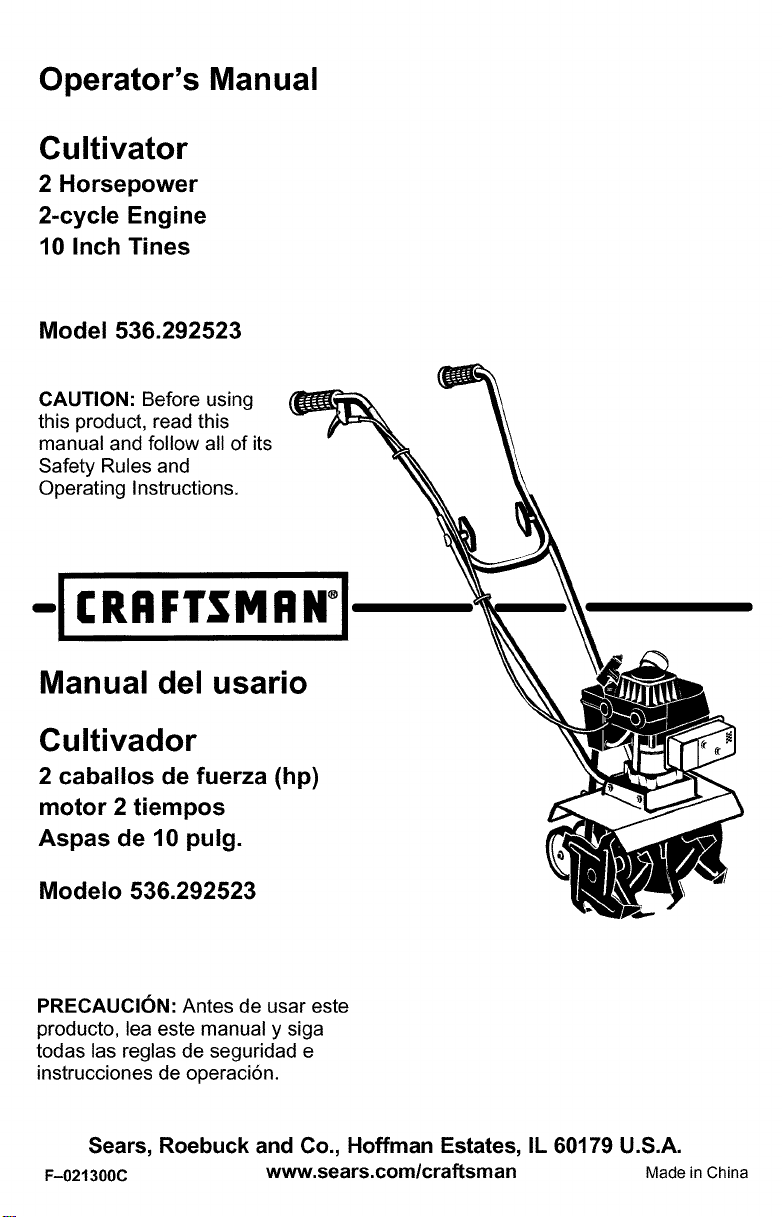
Operator's Manual
Cultivator
2 Horsepower
2-cycle Engine
10 Inch Tines
Model 536.292523
CAUTION: Before using
this product, read this
manual and follow all of its
Safety Rules and
Operating Instructions.
- CRRFTSMRN °
Manual del usario
Cultivador
2 caballos de fuerza (hp)
motor 2 tiempos
Aspas de 10 pulg.
Modelo 536.292523
PRECAUCI6N: Antes de usar este
producto, lea este manual y siga
todas las reglas de seguridad e
instrucciones de operaci6n.
Sears, Roebuck and Co., Hoffman Estates, IL 60179 U.S.A.
F-021300C www.sears.com/craftsman Made in China
Page 2

TABLE OF CONTENTS
WARRANTY STATEMENT ...... 2
SAFETY RULES ............... 3
INTERNATIONAL SYMBOLS .... 5
ASSEMBLY ................... 6
OPERATION .................. 8
MAINTENANCE ............... 13
SERVICE AND ADJUSTMENT .. 16
TROUBLE SHOOTING CHART .. 19
REPAIR PARTS ............... 20
ENGINE REPAIR PARTS ....... 25
SPANISH (ESPAI_IOL) .......... 31
PARTS ORDERING/SERVICE ..
BACK COVER
WARRANTY STATEMENT
LIMITED ONE-YEAR WARRANTY ON CRAFTSMAN CULTIVATOR
For one year from the date of purchase, when this Craftsman Cultivator is maintained, lubri-
cated, and tuned up according to the operating and maintenance instructions inthe owner's
manual, Sears will repair, free of charge, any defect in material or workmanship.
This warranty excludes tine(s), spark plug, and air cleaner which are expendable parts and
become worn during normal use.
Ifthis Craftsman Cultivator is used for commercial or rental purposes, this warranty applies
for only 90 days from the date of purchase.
WARRANTY SERVICE IS AVAILABLE BY RETURNING THE CRAFTSMAN CULTIVA-
TOR TO THE NEAREST SEARS SERVICE CENTER/DEPARTMENT IN THE UNITED
STATES. THIS WARRANTY APPLIES ONLY WHILE THIS PRODUCT IS IN USE IN THE
UNITED STATES.
This warranty gives you specific legal rights, and you may also have other rightswhich may
vary from state to state.
Sears, Roebuck and Co., D817WA, Hoffman Estates. IL 60179
Engine Exhaust, some of its constituents, and
certain vehicle components contain or emit
chemicals known to the State of California to
cause cancer and birth defects or other repro-
ductive harm.
Battery posts, terminals and related accessories
contain lead and lead compounds, chemicals
known to the State of California to cause cancer
and birth defects or other reproductive harm.
WASH HANDS AFTER HANDLING.
IMPORTANT: This unit is equipped with an internal combustion engine and must not be
used on or near any unimproved forest-covered, brush-covered or grass-covered land
unless the engine's exhaust system is equipped with a spark arrester meeting
applicable local or state laws (if any). If a spark arrester is used, it must be maintained in
effective working order by the operator.
In the State of California the above is required by law (Section 4442 of the California
Public Resources Code). Other states may have similar laws. Federal laws apply on fed-
eral lands. See a Sears Authorized Service Center for a spark arrester for the muffler.
F-021300C 2
Page 3
IMPORTANT
Safe Operation Practices for Cultivator
WARNING: Look for this symbol to point out important safety precautions.
It means: "Attention! Become Alert! Your Safety Is Involved."
_ ARNING: To prevent acciden-
ing repairs, always disconnect spark
plug wire and put wire where it cannot
contact the spark plug.
IMPORTANT: Safety standards require opera-
tor presence controls to minimize the risk of in-
jury. Your cultivator is equipped with such
controls. Do not attempt to defeat the function
of the operator presence control under any cir-
cumstances.
Before Use
• Read the owner's manual carefully. Be
• Do not operate the cultivator without wear-
• Keep the area of operation clear of all per-
• Thoroughly inspect the area where the cul-
Fuel Safety
• Handle fuel with care; it is highly flam-
• Use an approved container.
• Check fuel supply before each use, allow-
• Fill fuel tank outdoors with extreme care.
• Never remove the fuel tank cap or add fuel
F-021300C
tal starting when setting-up,
transporting, adjusting or mak-
thoroughly familiar with the controls and
the proper use of the cultivator. Know how
to stop the cultivator and disengage the
controls quickly.
ing adequate outer garments. Wear foot-
wear that will improve footing on slippery
surfaces.
sons, particularly small children and pets.
tivator is to be used and remove all foreign
objects.
mable.
ing space for expansion as the heat of the
engine and/or sun can cause fuel to ex-
pand.
Never fill fuel tank indoors. Replace fuel
tank cap securely and wipe up spilled fuel.
to a running or hot engine.
• Never store fuel or cultivator with fuel in the
tank inside a building where fumes may
reach an open flame.
Operating Safety
Never allow children or young teenagers to
operate the cultivator. Keep them away
while it is operating. Never allow adults to
operate the cultivator without proper in-
struction.
Do not operate this machine if you are tak-
ing drugs or other medication which can
cause drowsiness or affect your ability to
operate this machine.
Do not use this machine if you are mentally
or physically unable to operate this ma-
chine safely.
Always wear safety glasses or eye shields
during operation or while performing an
adjustment or repair to protect your eyes
from foreign objects that may be thrown
from the cultivator.
Do not put hands or feet near or under ro-
tating parts.
Exercise extreme caution when operating
on or crossing gravel drives, walks, or
roads. Stay alert for hidden hazards or
traffic.
Exercise caution to avoid slipping or falling.
Never operate the cultivator without proper
guards, plates, or other safety protective
devices in place.
Never operate the cultivator at high trans-
port speeds on slippery surfaces. Look be-
hind and use care when backing.
Never allow bystanders near the cultivator.
Keep children and pets away while
operating.
Never operate the cultivator without good
visibility or light.
Do not run the engine indoors. The ex-
haust fumes are dangerous, containing
CARBON MONOXIDE, an ODORLESS
and DEADLY GAS.
Page 4
IMPORTANT
• Take all possible precautions when leaving and keep the wire away from the plug to
the cultivator unattended. Stop the engine, prevent accidental starting. Thoroughly in-
• Do not overload the cultivator capacity by repair the damage before restarting and
attempting to till too deep at too fast a rate. operating it.
spect the cultivator for any damage, and
Safe Storage
• Always refer to the owner's manual instruc-
tions for important details if the cultivator is
to be stored for an extended period.
• Never store the cultivator with fuel in the
fuel tank inside a building where ignition
sources are present such as water and
space heaters, clothes dryers, and the like.
Allow the engine to cool before storing in
any enclosure.
• Keep the cultivator in safe working condi-
tion. Check all fasteners at frequent inter-
vals for proper tightness.
Repair / Adjustments Safety
• After striking a foreign object, stop the en-
gine. Remove the wire from the spark plug,
If cultivator should start to vibrate abnor-
mally, stop engine and check immediately
for the cause. Vibration is generally a warn-
ing of trouble.
Stop the engine whenever you leave the
operating position. Also, disconnect the
spark plug wire before unclogging the tines
and when making any repairs, adjust-
ments, or inspections.
• When cleaning, repairing, or inspecting,
shut off the engine and make certain all
moving parts have stopped.
Never attempt to make any adjustments
while the engine is running except when
specifically recommended by the manufac-
turer.
F-021300C 4
Page 5
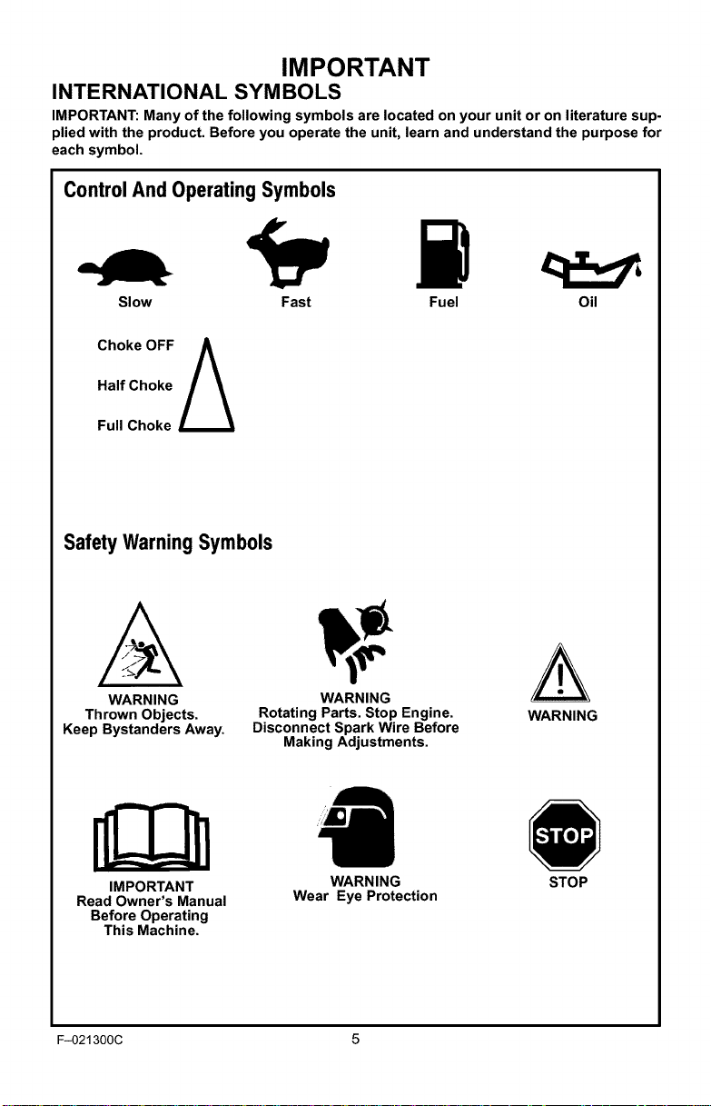
IMPORTANT
INTERNATIONAL SYMBOLS
IMPORTANT: Many of the following symbols are located on your unit or on literature sup-
plied with the product. Before you operate the unit, learn and understand the purpose for
each symbol.
ControlAnd Operating Symbols
Slow Fast Fuel Oil
Half Choke
Choke OFF A
Full Choke
Safety Warning Symbols
WARNING
Thrown Objects.
Keep Bystanders Away.
IMPORTANT
Read Owner's Manual
Before Operating
This Machine.
F-021300C 5
Rotating Parts. Stop Engine.
Disconnect Spark Wire Before
WARNING
Making Adjustments.
WARNING
Wear Eye Protection
WARNING
STOP
Page 6
ASSEMBLY
ASSEMBLY
PARTS PACKED SEPARATELY
IN CARTON
,/ ?-_
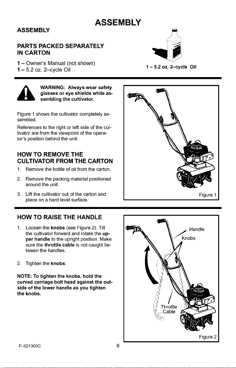
1- Owner's Manual (not shown)
1- 5.2 oz. 2-cycle Oil
glasses or eye shields while as-
WARNING: Always wear safety
sembling the cultivator.
Figure 1 shows the cultivator completely as-
sembled.
References to the right or left side of the cul-
tivator are from the viewpoint of the opera-
tor's position behind the unit.
HOW TO REMOVE THE
CULTIVATOR FROM THE CARTON
1. Remove the bottle of oil from the carton.
2. Remove the packing material positioned
around the unit.
3. Lift the cultivator out of the carton and
place on a hard level surface.
HOW TO RAISE THE HANDLE
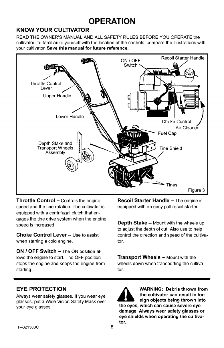
Loosen the knobs (see Figure 2). Tilt
the cultivator forward and rotate the up-
per handle to the upright position. Make
sure the throttle cable is not caught be-
tween the handles.
1 - 5.2 oz. 2-cycle Oil
Figure 1
_Kn Handle
obs
2. Tighten the knobs.
NOTE: To tighten the knobs, hold the
curved carriage bolt head against the out-
side of the lower handle as you tighten
the knobs.
F-021300C 6
Figure 2
Page 7

ASSEMBLY
v" CHECKLIST
For the best performance and satisfaction
from this quality product, please review the
following checklist before you operate the
cultivator:
_' All assembly instructions have been
completed.
_' Check carton. Make sure no loose
parts remain in the carton.
_' All fasteners have been properly tight-
ened.
As you learn how to use the cultivator, pay
extra attention to the following important
items:
_'_' Fuel tank is filled with a fresh, clean,
fuel mixture.
_'_' Become familiar and understand the
function of all controls. Before you
start the engine, operate all controls.
F-021300C 7
Page 8
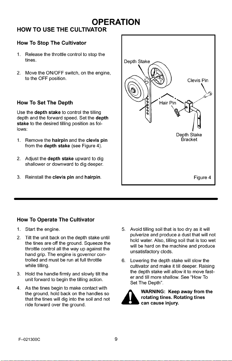
OPERATION
KNOW YOUR CULTIVATOR
READ THE OWNER'S MANUAL AND ALL SAFETY RULES BEFORE YOU OPERATE the
cultivator. To familiarize yourself with the location of the controls, compare the illustrations with
_our cultivator. Save this manual for future reference.
ON / OFF
Switch
J
Throttle Control
Lever
Upper Handle
Recoil Starter Handle
Lower Handle
Depth Stake and _
Tra n_sP°e_mW,y_
Throttle Control - Controls the eng=ne
speed and the tine rotation. The cultivator is
equipped with a centrifugal clutch that en-
gages the tine drive system when the engine
speed is increased.
Choke Control Lever- Use to assist
when starting a cold engine.
ON / OFF Switch - The ON position al-
lows the engine to start. The OFF position
stops the engine and keeps the engine from
starting.
Choke Control ._
Air Cleaner
Fuel Cap
Tine Shield
/
Tines
Figure 3
Recoil Starter Handle - The engine is
equipped with an easy pullrecoil starter.
Depth Stake - Mount with the wheels up
to adjust the depth of cut. Also use to help
control the direction and speed of the cultiva-
tor.
Transport Wheels - Mount with the
wheels down when transporting the cultiva-
tor.
EYE PROTECTION
Always wear safety glasses. If you wear eye
glasses, put a Wide Vision Safety Mask over
your eye glasses.
F-021300C
,_ WARNING: Debris thrown from
the eyes, which can cause severe eye
damage. Always wear safety glasses or
eye shields when operating the cultiva-
tor.
the cultivator can result in for-
eign objects being thrown into
Page 9
OPERATION
HOW TO USE THE CULTIVATOR
How To Stop The Cultivator
1. Release the throttle control to stop the
tines.
2. Move the ON/OFF switch, on the engine,
to the OFF position.
How To Set The Depth
Use the depth stake to control the tilling
depth and the forward speed. Set the depth
stake to the desired tilling position as fol-
lows:
1. Remove the hairpin and the clevis pin
from the depth stake (see Figure 4).
2. Adjust the depth stake upward to dig
shallower or downward to dig deeper.
Depth Stake
Clevis Pin
Depth Stake
Bracket
3. Reinstall the clevis pin and hairpin.
How To Operate The Cultivator
1. Start the engine.
2. Tilt the unit back on the depth stake until
the tines are off the ground. Squeeze the
throttle control all the way up against the
hand grip. The engine is governor con-
trolled and must be run at full throttle
while tilling.
3. Hold the handle firmly and slowly tilt the
unit forward to begin the tilling action.
4. As the tines begin to make contact with
the ground, hold back on the handles so
that the tines will dig into the soil and not
ride forward over the ground.
F-021300C 9
Figure 4
5.
Avoid tilling soil that is too dry as it will
pulverize and produce a dust that will not
hold water. Also, tilling soil that is too wet
will be hard on the machine and produce
unsatisfactory clods.
6. Lowering the depth stake will slow the
cultivator and make it till deeper. Raising
the depth stake will allow it to move fast-
er and till more shallow. See "How To
Set The Depth".
_ ARNING: Keep away from the
rotating tines. Rotating tines
can cause injury.
Page 10
OPERATION
BEFORE STARTING THE ENGINE
How To Prepare The Engine
_ ARNING: Always use a safety
fuel container. Do not smoke
when adding the fuel mixture to
the engine. When inside an enclosure,
do not fill the fuel tank. Before you add
the fuel mixture, stop the engine. Let the
engine cool for several minutes.
How To Mix The Fuel Mixture
The two cycle engine, used on this cultivator,
requires a mixture of gasoline and oil for lu-
brication of the bearings and other moving
parts. The correct fuel mixture ratio is 24:1
(5.2 oz. oil per one gallon of gas - see the
Fuel Mixture Chart). Gasoline and oil must
be pre-mixed in a clean gasoline container.
Always use fresh, clean, unleaded gasoline.
Mix gasoline and oil as follows:
1. Pour one (1) U.S. quart offresh, clean,
unleaded automotive gasoline into a one
gallon size gasoline container.
2. Add 5.3 ounces of clean, high quality,
two-cycle oil to the gasoline container.
IMPORTANT: Do not use outboard mo-
tor oil or multi-viscosity oils,such as
10W-30 or 10W-40.
3.
Install the fuel cap onto the gasoline con-
tainer. Vigorously shake the gasoline
container to mix the oil with the gasoline.
4.
Add an additional three (3) U.S. quarts of
gasoline to the gallon container. Again
shake the gasoline container.
5.
This completes the gasoline mixing pro-
cedure. The gasoline can now be added
to the fuel tank.
FUEL MIXTURE CHART (mixture 24:1)
U.S. SI. (Metric
GAS OIL GAS OIL
1 Gal. 5.2 oz. 4 Liters .167 L
2 Gal. 11 oz. 8 Liters .333 L
5 Gal. 27 oz. 20 Liters .833 L
Do not fill the fuel tank with gasoline that does not have oil mixed in it. Shake the
gasoline container before each filling of the fuel tank.
OII Add more gas
(5.2 oz)_ Shake Can (3 U. S. Quarts)
4- +
] U.S. Gallon container _-_
F-021300C 10
Page 11
OPERATION
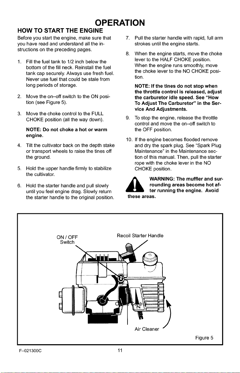
HOW TO START THE ENGINE
Before you start the engine, make sure that
you have read and understand all the in-
structions on the preceding pages.
Fill the fuel tank to 1/2 inch below the
bottom of the fill neck. Reinstall the fuel
tank cap securely. Always use fresh fuel.
Never use fuel that could be stale from
long periods of storage.
2.
Move the on-off switch to the ON posi-
tion (see Figure 5).
Move the choke control to the FULL
CHOKE position (all the way down).
NOTE: Do notchokea hot orwarm
engine.
4.
Tilt the cultivator back on the depth stake
or transport wheels to raise the tines off
the ground.
5.
Hold the upper handle firmly to stabilize
the cultivator.
7. Pull the starter handle with rapid, full arm
strokes until the engine starts.
8.
When the engine starts, move the choke
lever to the HALF CHOKE position.
When the engine runs smoothly, move
the choke lever to the NO CHOKE posi-
tion.
NOTE: If the tines do not stop when
the throttle control is released, adjust
the carburetor idle speed. See "How
To Adjust The Carburetor" in the Ser-
vice And Adjustments.
g.
To stop the engine, release the throttle
control and move the on-off switch to
the OFF position.
10.
If the engine becomes flooded remove
and dry the spark plug. See "Spark Plug
Maintenance" in the Maintenance sec-
tion of this manual. Then, pull the starter
rope with the choke lever in the NO
CHOKE position.
6. Hold the starter handle and pull slowly
until you feel engine drag. Slowly return
the starter handle to the original position.
ON / OFF
Switch
F-021300C 11
,_ WARNING: The muffler and sur-
rounding areas become hot af-
ter running the engine. Avoid
these areas.
Recoil Starter Handle
Air Cleaner "_
Figure 5
Page 12
CULTIVATING TIPS
Tilling is digging in, turning over and
breaking up packed soil before planting.
Loose unpacked soil helps root growth.
Best tilling depth is 4 to 6 inches. A tiller
will also clear the soil of unwanted vege-
tation. The decomposition of this vegeta-
tion matter enriches the soil. Depending
on the climate (rainfall and wind), it may
be advisable to till the soil at the end of
the growing season to further condition
the soil.
Avoid tilling soil that is too dry as it will
pulverize and produce a dust that will not
hold water. Also, tilling soil that is too wet
will be hard on the machine and produce
unsatisfactory clods.
Better growth will be obtained if an area
is tilled properly and used soon after till-
ing to preserve the moisture content.
The depth stake (on the back of the culti-
vator) serves a dual purpose. It helps
regulate the depth of the cut and also
acts as a brake to help the operator con-
trol the speed of the cultivator.
Lowering the depth stake will slow the
cultivator and make it till deeper. Raising
the depth stake will allow it to move fast-
er and till more shallow.
OPERATION
all safety devices and shields in place.
Never allow children or uninstructed
adults to operate cultivator. Shut off en-
gine before unclogging tines or making
repairs. Keep bystanders away from ma-
chine. Keep away from rotating parts
and tines. They can cause injury.
If the cultivator stops forward motion and
tries to dig deeper than necessary, move
the handles from side to side to start for-
ward motion.
Cultivating is loosening or digging
around growing plants which allows the
plants to flourish.
When using the cultivator to remove
weeds, it is best to cultivate no deeper
than 1-1/2 inches. Cultivating deeper will
only pull to the surface ungerminated
weed seeds. Raising the depth stake will
allow it to move faster and till more shal-
low.
When cultivating around plants or close
areas, you may want to remove the out-
side tines. See "Tine Replacement" in
the Service/Adjustments section.
manual. Know location and
WARNING: Read the Owner's
functions of all controls. Keep
F-021300C 12
Page 13
MAINTENANCE
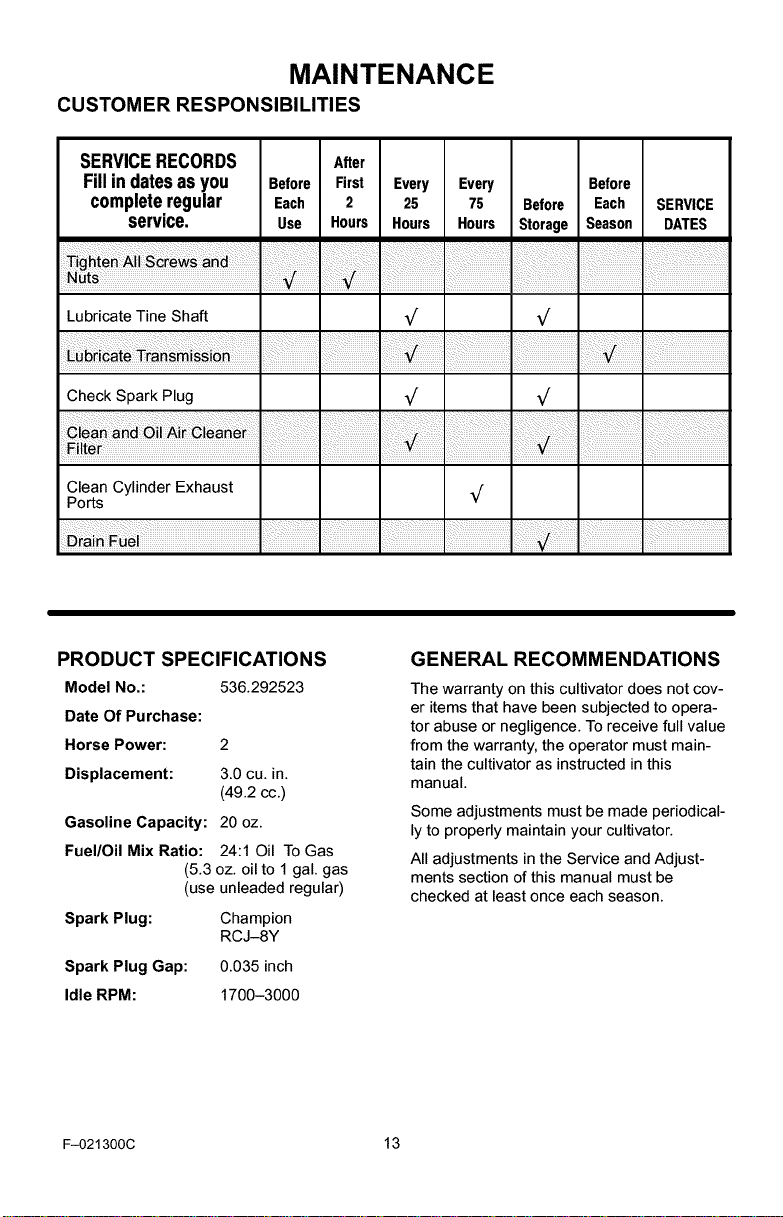
CUSTOMER RESPONSIBILITIES
SERVICERECORDS After
Fillin datesasyou Before First Every Every Before
completeregular Each 2 25 75 Before Each SERVICE
service. Use Hours Hours Hours Storage Season DATES
Lubricate Tine Shaft
ill
Check Spark Plug _/ _/
Clean Cylinder Exhaust _/
Ports
PRODUCT SPECIFICATIONS
Model No.:
Date Of Purchase:
Horse Power:
Displacement:
Gasoline Capacity:
Fuel/Oil Mix Ratio:
Spark Plug:
Spark Plug Gap:
Idle RPM:
F-021300C 13
536.292523
2
3.0 cu. in.
(49.2 cc.)
20 oz.
24:1 Oil To Gas
(5.3 oz. oil to 1 gal. gas
(use unleaded regular)
Champion
RCJ-8Y
0.035inch
1700-3000
GENERAL RECOMMENDATIONS
The warranty on this cultivator does not cov-
er items that have been subjected to opera-
tor abuse or negligence. To receive full value
from the warranty, the operator must main-
tain the cultivator as instructed in this
manual.
Some adjustments must be made periodical-
ly to properly maintain your cultivator.
All adjustments in the Service and Adjust-
ments section of this manual must be
checked at least once each season.
Page 14
MAINTENANCE
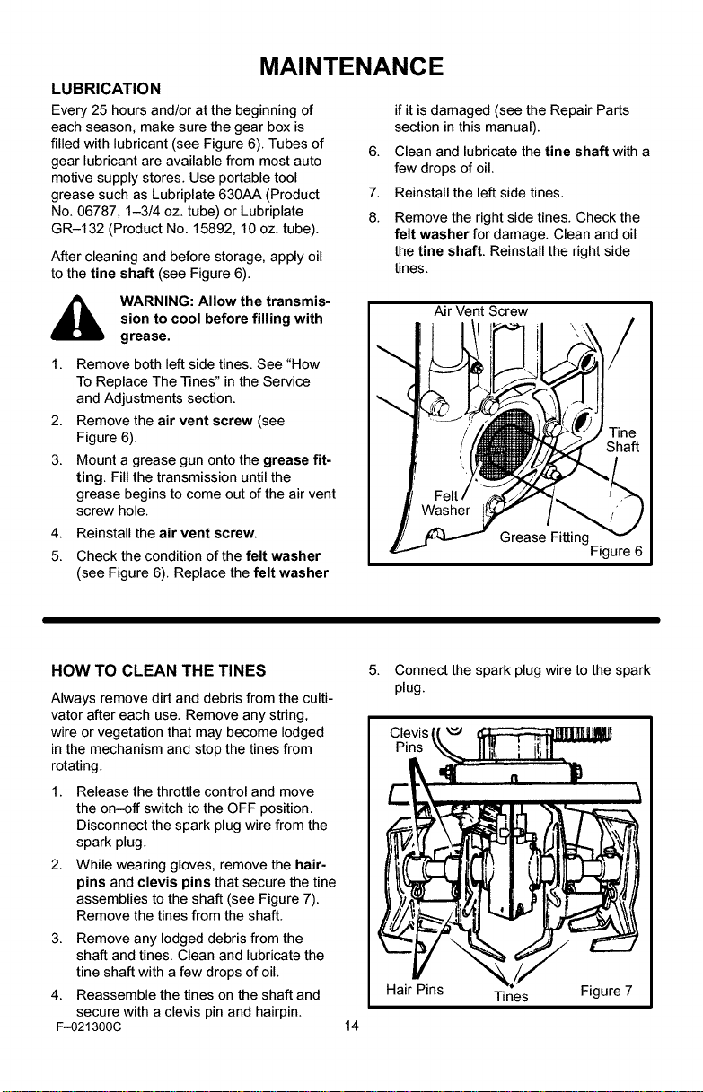
LUBRICATION
Every 25 hours and/or at the beginning of
each season, make sure the gear box is
filled with lubricant (see Figure 6). Tubes of
gear lubricant are available from most auto-
motive supply stores. Use portable tool
grease such as Lubriplate 630AA (Product
No. 06787, 1-3/4 oz. tube) or Lubriplate
GR-132 (Product No. 15892, 10 oz. tube).
After cleaning and before storage, apply oil
to the fine shaft (see Figure 6).
if it is damaged (see the Repair Parts
section in this manual).
6.
Clean and lubricate the fine shaft with a
few drops of oil.
7.
Reinstall the left side tines.
8.
Remove the right side tines. Check the
felt washer for damage. Clean and oil
the fine shaft. Reinstall the right side
tines.
sion to cool before filling with
WARNING: Allow the transmis-
grease.
1. Remove both left side tines. See "How
To Replace The Tines" in the Service
and Adjustments section.
2. Remove the air vent screw (see
Figure 6).
3. Mount a grease gun onto the grease fit-
ting. Fill the transmission until the
grease begins to come out of the air vent
screw hole.
4. Reinstall the air vent screw.
5. Check the condition of the felt washer
(see Figure 6). Replace the felt washer
HOW TO CLEAN THE TINES
Always remove dirt and debris from the culti-
vator after each use. Remove any string,
wire or vegetation that may become lodged
in the mechanism and stop the tines from
rotating.
1. Release the throttle control and move
the on-off switch to the OFF position.
Disconnect the spark plug wire from the
spark plug.
2. While wearing gloves, remove the hair-
pins and clevis pins that secure the tine
assemblies to the shaft (see Figure 7).
Remove the tines from the shaft.
3. Remove any lodged debris from the
shaft and tines. Clean and lubricate the
tine shaft with a few drops of oil.
4. Reassemble the tines on the shaft and
secure with a clevis pin and hairpin.
F-021300C
Air Vent Screw
Grease Fitting
5.
Connect the spark plug wire to the spark
plug.
Hair Pins Tines Figure 7
14
Figure 6
Page 15
MAINTENANCE
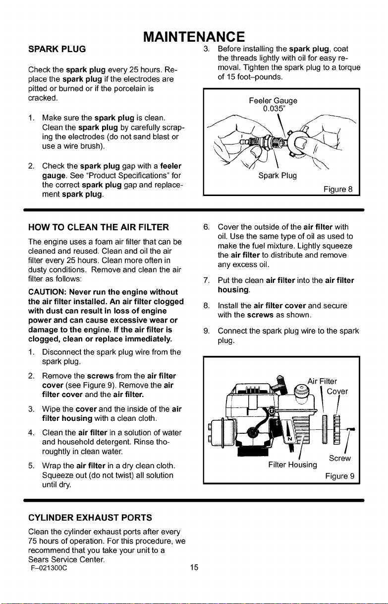
SPARK PLUG
Check the spark plug every 25 hours. Re-
place the spark plug if the electrodes are
pitted or burned or ifthe porcelain is
cracked.
Make sure the spark plug is clean.
Clean the spark plug by carefully scrap-
ing the electrodes (do not sand blast or
use a wire brush).
2.
Check the spark plug gap with a feeler
gauge. See "Product Specifications" for
the correct spark plug gap and replace-
ment spark plug.
3. Before installing the spark plug, coat
the threads lightly with oil for easy re-
moval. Tighten the spark plug to a torque
of 15 foot-pounds.
Feeler Gauge
0.035"
Spark Plug
Figure 8
HOW TO CLEAN THE AIR FILTER
The engine uses a foam air filter that can be
cleaned and reused. Clean and oil the air
filter every 25 hours. Clean more often in
dusty conditions. Remove and clean the air
filter as follows:
CAUTION: Never run the engine without
the air filter installed. An air filter clogged
with dust can result in loss of engine
power and can cause excessive wear or
damage to the engine. If the air filter is
clogged, clean or replace immediately.
1. Disconnect the spark plug wire from the
spark plug.
2. Remove the screws from the air filter
cover (see Figure 9). Remove the air
filter cover and the air filter.
3. Wipe the cover and the inside of the air
filter housing with a clean cloth.
4. Clean the air filter in a solution of water
and household detergent. Rinse tho-
roughtly in clean water.
5. Wrap the air filter in a dry clean cloth.
Squeeze out (do not twist) all solution
until dry.
6.
Cover the outside of the air filter with
oil. Use the same type of oil as used to
make the fuel mixture. Lightly squeeze
the air filter to distribute and remove
any excess oil.
7.
Put the clean air filter into the air filter
housing.
8.
Install the air filter cover and secure
with the screws as shown.
9.
Connect the spark plug wire to the spark
plug.
Air Filter
Filter Housing
Screw
Figure 9
CYLINDER EXHAUST PORTS
Clean the cylinder exhaust ports after every
75 hours of operation. For this procedure, we
recommend that you take your unit to a
Sears Service Center.
F-021300C 15
Page 16
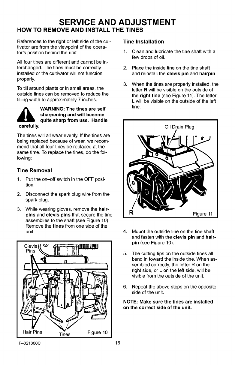
SERVICE AND ADJUSTMENT
HOW TO REMOVE AND INSTALL THE TINES
References to the right or left side of the cul-
tivator are from the viewpoint of the opera-
tor's position behind the unit.
All four tines are different and cannot be in-
terchanged. The tines must be correctly
installed or the cultivator will not function
properly.
To till around plants or in small areas, the
outside tines can be removed to reduce the
tilling width to approximately 7 inches.
sharpening and will become
WARNING: The tines are self
quite sharp from use. Handle
carefully.
The tines will all wear evenly. If the tines are
being replaced because of wear, we recom-
mend that all four tines be replaced at the
same time. To replace the tines, do the fol-
lowing:
Tine Removal
1. Put the on-off switch in the OFF posi-
tion.
2.
Disconnect the spark plug wire from the
spark plug.
3.
While wearing gloves, remove the hair-
pins and clevis pins that secure the tine
assemblies to the shaft (see Figure 10).
Remove the tines from one side of the
unit.
Clevis
Pins
Tine Installation
1. Clean and lubricate the tine shaft with a
few drops of oil.
2. Place the inside tine on the tine shaft
and reinstall the clevis pin and hairpin.
3.
When the tines are properly installed, the
letter R will be visible on the outside of
the right tine (see Figure 11). The letter
L will be visible on the outside of the left
tine.
Oil Drain Plug
R
4. Mount the outside tine on the tine shaft
and fasten with the clevis pin and hair-
pin (see Figure 10).
5.
The cutting tips on the outside tines all
bend in toward the inside tine. When as-
sembled correctly, the letter R on the
right side, or L on the left side, will be
visible from the outside of the unit.
Figure 11
Hair Pins Tines Figure 10
F-021300C
6. Repeat the above steps on the opposite
side of the unit.
NOTE: Make sure the tines are installed
on the correct side of the unit.
16
Page 17

SERVICE AND ADJUSTMENT
HOW TO ADJUST THE CARBURETOR
A dirty air cleaner will cause the engine to
run improperly or to smoke excessively. Be-
fore adjusting the carburetor, make sure the
air cleaner is clean. Never make unneces-
sary adjustments to the carburetor. The car-
buretor was set at the factory to operate
efficiently under most applications. However,
if adjustments are required, we recommend
you contact your nearest Sears Service Cen-
ter. If you feel that you are competent to
make carburetor adjustment proceed as fol-
lows.
when making adjustments that
WARNING: Use extreme care
require the engine to be run-
ning. Keep hands, feet, hair and loose
clothing away from all moving parts.
Turn the mixture adjustment screw
clockwise to until closed (see Figure 12).
IMPORTANT: To prevent damage to
the carburetor or to the adjusting
screw, tighten the adjustment screws
with your fingers.
2.
Turn the mixture adjustment screw
counterclockwise one turn.
3.
Start the engine and let it warm up for
approximately 3 to 5 minutes. Do not ad-
just the carburetor when the engine is
cold.
4.
If the engine runs erratically or stops af-
ter the choke lever is moved to the
CHOKE OFF position, then open the
mixture adjustment screw an addition-
al 1/8 turn counterclockwise.
5. With the engine running, release the
throttle control (idle position) to make the
mixture adjustments.
6. Slowly turn the mixture adjustment
screw clockwise until the engine begins
to run erratically. Note this position.
7.
Then, slowly turn the mixture adjustment
screw counterclockwise until the engine
again begins to run erratically. Note this
position.
8.
Turn the mixture adjusting screw clock-
wise until it is halfway between the first
position and the second position.
g.
Check the engine idle speed. Start the
engine and release the throttle control. If
the tines do not turn with the throttle con-
trol is released, the idle speed is correct.
If the tines turn with the throttle control is
released, adjust the engine idle speed as
follows.
10. Have someone tilt the cultivator back on
its depth stake so that the tines are off
the ground.
11. Start the engine.
12. With the throttle in the released (idle
position), turn the idle speed adjust-
ment screw counterclockwise until the
tines stop rotating.
nor is set at the factory. Do not
WARNING: The engine gover-
change the governor setting.
Over speeding the engine above the fac-
tory setting can be dangerous. Ifyou
think the engine governor needs an ad-
justment, contact your nearest Sears
Service Center.
Mixture
Idle Speed Adjustment Screw
Adjustment Screw
Engine Shown With Air Filter Removed
Figure 12
F-021300C 17
Page 18

SERVICE AND ADJUSTMENT
STORAGE
tivator indoors with fuel in the
WARNING: Never store the cul-
fuel tank. Never store in an en-
closed, poorly ventilated area where
fumes could reach an open flame, a
spark or a pilot light as on a furnace, wa-
ter heater or clothes dryer.
oline while inside a building,
WARNING: Do not remove gas-
Gasoline fumes can cause an explosion
or a fire.
When the cultivator is put in storage for thirty
days or more, follow the steps below to
make sure the cultivator is in good condition
the following season.
Cultivator
• Completely cleanthe cultivator.
• Remove the tines. Clean and apply oil to
• Loosen the knobs that secure the upper
• The cross piece of the upper handle (be-
• Put the cultivator in a building that has
near a fire, or while you smoke.
the tine shafts. Mount the tines onto the
tine shafts. See "How To Remove And
Install The Tines" in the Service And Ad-
justments section.
handle to the lower handle. Carefully fold
the upper handle. Make sure the throttle
cable is not bent. Tighten the knobs.
tween the lower handles) can now be
used as a carry handle. To store the cul-
tivator up off the floor and out of the way,
the cross piece can also be hooked over
a wall hook.
good ventilation.
• Cover the cultivator with a suitable pro-
tective cover that does not retain mois-
ture. Do not use plastic.
IMPORTANT: Never cover the cultivator
while the engine and exhaust areas are
still warm.
NOTE: A yearly checkup or tune-up by a
Sears Service Center is a good way to
make sure that your cultivator will pro-
vide maximum performance for the next
season.
Engine
IMPORTANT: It is important to prevent
gum deposits from forming in fuel system
parts such as the carburetor, fuel filter,
fuel hose, and tank during storage. Also,
using alcohol-blended fuels (called gaso-
hol, ethanol or methanol) can attract
moisture which leads to separation and
formation of acids during storage. Acidic
gas can damage the fuel system of an en-
gine while in storage.
To prevent engine damage when the cultiva-
tor is in storage for 30 days or more, follow
the steps below:
• Let the engine run until it is out of gaso-
line.
Slowly pull the starter handle until you
feel resistance due to compression in
the cylinder, then stop.
Slowly release the starter rope. This
position will close both the intake and the
exhaust ports and help prevent corrosion
of the piston and cylinder.
F-021300C 18
Page 19

TROUBLE SHOOTING CHART
TROUBLE
Engine difficult to start
or
Engine runs erratically
or
Enginewill not runatfull
speed
Engine speed does not
increase properly
Engine smokes
excessively
Tines continue to rotate
when throttle control is
released
Tines will not turn
CAUSE
Stale fuel mixture
Too much oil infuel mixture
Dirt in fuel tank or out offuel
Carburetor out ofadjustment
Fouled spark plug
Dirty air filter
Debris interfering with throttle
linkage
Plugged air filter
Too much oil infuel mixture
Carburetor out ofadjustment
Debris lodged in tine
CORRECTION
Drain fuel tank. Fill with fresh
fuel mixture.
Check fuel mixture chart and
mix fresh fuel.
Clean fuel tank.
See Carburetor Adjustment
section.
Clean and set spark plug
gap.
Clean and oil air filter.
Clean dirt and debris of top
of carburetor.
Clean and oil air filter.
Check fuel mix chart and mix
fresh fuel.
Adjust carburetor idle speed.
See "How To Adjust The
Carburetor" in the
Maintenance section.
Remove debris. See "How
To Clean The Tines" in the
Maintenance section.
Unit does not till properly
F-021300C 19
Incorrect tine installation
Check the tines for proper
installation. See "How To
Remove And Install The
Tines" in the Service And
Adjustments section.
Page 20

CRAFTSMAN 536.292523 REPAIR PARTS
17
10
11
KEY
NO. PARTNO.
10 2.0HP
11 56694
12 335350
13 120380
14 180042
F-021300C 20
DESCRIPTION
Engine 143.002072 17 319306 Cable, Throttle
Flat washer -- F-021300C Instruction Manual
Rotor -- 48x896 Decal, Craftsman
Washer
Screw
13
14 323392C
KEY
NO. PARTNO. DESCRIPTION
2.0/10
Page 21

CRAFTSMAN 536.292523 REPAIR PARTS
310
300
KEY
NO.
PARTNO.
300
740061
310
340550
311
180024
312
782585
F-021300C 21
318848C
DESCRIPTION
Transmission
Bracket, Depth Rod
Screw, 1/4-20xl.25
Nut, 1/4-20
Page 22

CRAFTSMAN 536.292523 REPAIR PARTS
482
496
496
KEY KEY
NO. PARTNO. DESCRIPTION NO. PARTNO. DESCRIPTION
480 309073-848 Shield, Tine
481 273869 Screw,
1/4-20x5.00
482 120392 Flat washer
483 46931 Nut, 1/4-20
490 56158 Washer, Felt
491 56157-853 Tine Assy. Inner
LH
493 56156-853 TineAssy. Inner
494 56154-853 Tine Assy. Outer
495 56123 Clevis Pin
496 56180 Hair Pin
490
318849c
RH
RH
-- 320711 Decal, Caution
-- 712457 Decal, Tine Shield
492 56155-853 Tine Assy. Outer
F-021300C 22
LH
Page 23

CRAFTSMAN 536.292523 REPAIR PARTS
662
661
663
KEY
NO. PARTNO.
650 330799-853
660 333635
661 56180
662 339277
663 73664
F-021300C 23
318852G
DESCRIPTION
Wheel Support Assy.
Clevis Pin
Hair Pin
Tire & Rim
Push On Nut
Page 24

CRAFTSMAN 536.292523 REPAIR PARTS
947
930
948
944
941
934
F-021300C
KEY
NO.
930
932
934
941
942
943
944
945
946
947
948
PARTNO.
56237-853
339398-853
339399-853
56199
783000
120393
57171
120376
56778
426635
712267
305828
319375C
DESCRIPTION
Upper Handle
Lower Handle LH
Lower Handle RH
Bolt 5/16-18xl .63
Formed Washer
Flat washer
T Knob
Nut, 5/16-18
Hand Grip
Screw, 10-16xl.50
Cable Tie
Decal, Caution (Starting)
24
Page 25

CRAFTSMAN 143.002072 REPAIR PARTS
275 *
F-021300C 25
Page 26

CRAFTSMAN 143.002072 REPAIR PARTS
KEY PART KEY PART
NO. NO. DESCRIPTION NO. NO.
0 RPM High 5000 to 5400 93 650849
DESCRIPTION
Flywheel Nut
0 RPM Low 1700 to 3000 100 611056
1 250303 Cylinder (Incl. 119, 184,
187 & 187A) 101 610118
3 650888 Screw, T-30 103 651007
13 270288A Crankcase Ass'y. 110 611135
(Incl. 20, 44 & 69)
119 510349
13A 270298 Crankcase Cover
135 611049
16B 490324 Air Vane
16C 650986 Screw, T-8, 3-48 x 7/32" 177 650858
19 570716 Governor Spring 178 650580
20 510328 Oil Seal 184 510327B
30 290664 Crankshaft 187 570648A
39 310285A Piston & Rod Assy. 187A 570698A
(Incl. 42)
200 570700
42 310275 Ring Set
203 570701
44 530163 Cartridge Bearing
204 651042
69 510348 "O" Ring
209 651042
77 530110 Ball Bearing
210 27793
78 510319 Oil Seal
211 651047
79 650844 Screw, 1/4-20 x 3/4"
216 570712
89 611054 Flywheel Key
230 570649A
90 611180 Flywheel
243 650955
91 590691 Pawl Spring
243A 650964
91A 590692 Starter Pawl
245 450252
91B 650985 Screw, 12-24 x 11/64"
245A 450255
92 650848 Belleville Washer
Solid State Ignition
(Incl. 101)
Spark Plug Cover
Screw, T-15
Ground Wire
Cylinder Head Gasket
Resistor Spark Plug
(RCJ8Y)
Carburetor Mounting Stud
Lock Nut, 10-24
Carburetor Gasket
Spacer
Air Baffle (Incl. 184 & 187)
Speed Control Body
Compression Spring
Screw, T-15, 8-32 x 1"
Screw, T-15, 8-32 x 1"
Conduit Clip
Screw, T-15
R.PM. Adjusting Lever
"O" Ring
Screw, 10-32 x 29/32"
Thread Insert
Air Filter (Poly)
Air Filter (Flocked)
F-021300C 26
Page 27

CRAFTSMAN 143.002072
250 450253 Air Cleaner Cover
REPAIR PARTS
301 410280 Fuel Cap
257 650867 Screw, 10-24 x 1/2"
258 350435 Blower Housing Base
261 650850 Screw, 8-32 x 1-9/16"
262 650939 Stud
274 510347 Exhaust Gasket
275 390322 Muffler (Incl. 274 & 277) 370Q 550247 Emissions Decal
277 650938 Screw, 1/4-20 x 2.409"
290 410246A Fuel Line
292 410253 Fuel Line Clamp 520 0
297 27261 Washer 900 0
298 650954 Lock Nut, 8-32
300 410277A Fuel Tank (Incl. 290,292, 900 0
298,301 & 370C)
326 570659 Blower Housing Plug
331 610650B Toggle Switch
370C 550239 Choke Decal
370D 35977 Caution Decal
370G 550228 Instruction Decal
380 640231 Carburetor (Incl. 184)
391 590690 Recoil Starter Ass'y.
Clutch (Supplied by OEM)
Replacement Engine
710580, order from
71-999
Replacement S/B
710542B, order from
71-999
F-021300C 27
Page 28

CRAFTSMAN 143.002072 REPAIR PARTS
60
iS0
F-021300C 28
Page 29

CRAFTSMAN 143.002072 REPAIR PARTS
KEY PART
NO. NO.
0 640231
1 640232
2 640233
3 640234
3B 640236
4 640237
5 640238
6 640239
7 640235
17 640240
27 640241
28 640242
30 640243
31 640244
34 640245
40 640246
40A 640247
50 640248
51 640249
52 640250
53 640251
60 640256
62 640252
63 640253
64 640255
65 640254
70 640257
Carburetor (Incl. 184 of Engine Parts List)
Throttle Shaft & Lever Ass'y.
Throttle Return Spring
Dust Seal Retainer
Spacer
Dust Seal Washer
Dust Seal
Throttle Shutter
Screw, Throttle Shutter & Dust Seal Retainer
Idle Speed Screw
Hinge Pin
Metering Lever
Inlet Needle
Metering Lever Spring
Screw, Metering Lever Pin
High Speed Jet
High Speed Jet Sealer Cap
Diaphragm (Included in Gasket Set)
Cover Gasket (Included in Gasket Set)
Cover
Cover Screw
Repair kit (Incl. Items Marked PK in Notes)
Incl. (1) each of part #'s 640242, 640243,
640257
Pump Diaphragm (Incl. in Gasket Set)
Pump Gasket (Included in Gasket Set)
Pump Cover
Pump Cover Screw
Gasket Set Incl. (1) each of part #'s 640248,
640249, 640252, 640253
DESCRIPTION
F-021300C 29
Page 30

CRAFTSMAN 143.002072 REPAIR PARTS
F-021300C
KEY
NO.
0
1
3
4
5
6
8
9
12
13
PART
NO. DESCRIPTION
590690 Rewind Starter & Housing Ass'y.
650987 Retainer Screw, 10-24 x 1-3/8"
650985 Pawl Screw, 12-24 x 11/64"
650147 Washer
590691 Pawl Spring
590692 Pawl
590693 Pulley
590562 Rewind Spring
590639 Starter Rope (#4 rope, 71" long)
590452 Starter Handle
30
Page 31

CONTENIDO
GARANTiA .................... 31
NORMAS DE SEGURIDAD ..... 32
S[MBOLOS INTERNACIONALES 34
MONTAJE .................... 35
OPERACI6N .................. 37
MANTENIMIENTO ............. 42
TABLADELOCALIZACI(_NDEAVERiAS 48
PIEZAS DE REPUESTO ........ 20
PIEZAS DE REPUESTO (MOTOR) 25
PEDIDOS/ SERVIClO CONTRACUBIERTA
GARANTiA
GARANTIA LIMITADA DE UN AI_IO PARA LA CULTIVADORA CRAFTSMAN
Esta cultivadora Craftsman esta garantizada por un aho a partir de la fecha de compra, siem-
prey cuando se le haya dado mantenimiento, lubricado y aflnado deacuerdo con las instruc-
clones de operaci6n y mantenimiento que aparecen en el manual del usuario, Sears repara-
ra, sin costo alguno, cualquier defecto en el material y/o mano de obra de la unidad.
Esta garantfa no cubre los dientes, bujias ni filtros de aire, los cuales son partes que se des-
gastan durante el uso normal de la unidad.
Siesta cultivadora Craftsman se utiliza para prop6sitos comerciales o de arrendamiento, la
garantfa sera valida por s61o90 dfas a partir de la fecha de compra.
EN LOS ESTADOS UNIDOS, EL SERVICIO BAJO GARANTiA PARA LA CULTIVADORA
CRAFTSMAN ESTA DISPONIBLE EN EL CENTRO / DEPARTAMENTO DE SERVICIO
SEARS MAS CERCANO. ESTA GARANTiA ES VALIDA SOLAMENTE MIENTRAS EL
PRODUCTO SE USE EN LOS ESTADOS UNIDOS.
Esta garantia le otorga derechos legales especfficos, ademas, usted puede tener otros dere-
chos legales que varfan segQn el estado donde resida.
Sears, Roebuck and Co., D817WA, Hoffman Estates. IL 60179
Las emanaciones de escape producidas por este
motor y ciertos componentes de esta mdquina
contienen agentes quimicos reconocidos por el
Estado de California como carcinbgenos, tambi_n
pueden producir defectos en los reci_n nacidos o
causar otros dafios al sistema reproductivo.
Los bornes, terminales y accesorios relacionados
con la bateria, contienen plomo y compuestos de
plomo. El Estado de California reconoce que es-
tos compuestos pueden causar cdncer y defectos
cong_nitos, ademds de otros dafios al sistema re-
productivo. DEBE LAVARSE MUY BIEN LAS MA-
NOS DESPUF:S DE MANIPULAR ESTOS COMPO-
NENTES.
IMPORTANTE: Esta unidad estd equipada con un motor de combustibn interna y no
debe ser usada en o cerca de ningt_n terreno basto de cubierta forestal, de maleza o de
hierba a menos que el sistema de escape del motor est_ equipado con un parachispas
que cumpla con las leyes locales o estatales aplicables (si existen). Si se usa el
parachispas, el operador debe mantenerlo en buenas condiciones.
En el Estado de California Io indicado anteriormente es exigido por ley (Seccibn 4442
del Cbdigo de Recursos Pdblicos de California). Otros estados pueden tener leyes simi-
lares. Las leyes federales aplican sobre los terrenos federales. Para conseguir un para-
chispas para el sistema de escape, acuda a un Centro de servicio autorizado de Sears.
F-021300C 31
Page 32

IMPORTANTE
Prdcticas para la operacibn segura de la cultivadora.
de precaucibn para su seguridad. Este simbolo quiere decir: "iAtencibn!
ADVERTENCIA: Busque este simbolo que le indicard puntos importantes
iEst_ alerta! Preste atencibn a su seguridad".
_ DVERTENCIA: Para prevenir
montaje, transporte, ajuste o reparacibn,
desconecte siempre el cable de la bujia y
colbquelo alejado de _sta.
IMPORTANTE: Las normas de seguridad re-
quieren que la unidad est6 equipada con con-
troles que funcionan solamente en la presencia
del operador para minimizar el riesgo de acci-
dentes. Su cultivadora esta equipada con tales
controles. Por ningQn motivo debe intentar anu-
lar la funci6n de estos controles que s61otraba-
jan en la presencia del operador.
Pasos preliminares
• Lea el Manual del usuario detenidamente.
• Siempre que use la cultivadora debera
• Mantenga el area de operaci6n despejada
• Examine completamente el area donde se
Combustible
• Tenga mucho cuidado al manejar gasolina
• Use Qnicamente recipientes aprobados.
• Revise el nivel de combustible cada vez
• Debe reabastecer 0 Ilenar el tanque de
F-021300C
el arranque accidental de la md-
quina durante los procesos de
Debe familiarizarse completamente con los
controles y con el uso correcto de la culti-
vadora. Aprenda c6mo apagar, detener y
desenganchar los controles de la cultiva-
dora, en caso de que tenga que hacerlo
rapidamente.
vestirse con ropa apropiada y usar zapatos
que Io protejan y le den buena tracci6n.
de personas, especialmente de nifios pe-
quefios y mascotas.
va a usar la cultivadora y desp6jela de
cualquier objeto.
y otros combustibles, estos son sumamen-
te inflamables.
que use la cultivadora. AsegQrese de dejar
suficiente espacio en el tanque, ya que el
calor del motor y/o del sol puede causar la
expansi6n del combustible.
combustible al aire libre y con mucho cui-
dado. Nunca I0 Ilene en un espacio cerra-
do. Fije bien la tapa del tanque de
combustible y limpie cualquier derrame.
Nunca quite la tapa del tanque de combus-
tible ni afiada combustible al tanque cuan-
do el motor est6 caliente 0 en marcha.
Nunca guarde la cultivadora Ilena de com-
bustible ni el recipiente de combustible en
un recinto donde los vapores del combusti-
ble puedan alcanzar alguna llama expues-
ta.
Operacibn
Nunca permita que nifios o adolescentes
manejen la cultivadora. Mant6ngalos fuera
del area de operaci6n. Nunca permita que
usen la unidad los adultos no familiariza-
dos con las instrucciones de operaci6n.
• No opere la cultivadora siesta tomando
algQn farmaco u otra medicina que le pro-
voque somnolencia o que afecte su habili-
dad de operar esta unidad con seguridad.
• No use la cultivadora si no esta ffsica o
mentalmente capacitado para hacerlo de
una manera segura.
• Siempre use gafas de seguridad o caretas
protectoras al operar, ajustar o reparar la
cultivadora, esto protegera sus ojos de ob-
jetos que pudieran ser lanzados por la uni-
dad.
• No ponga las manos o los pies cerca o de-
bajo de piezas giratorias.
• Preste mucha atenci6n cuando maneje la
cultivadora cerca de la calle, o cuando cru-
ce por calzadas, calles o caminos de gra-
va. Est6 alerta tanto del trafico como de
problemas potenciales o imprevistos.
• Tenga cuidado para evitar cafdas o resba-
Iones.
• Nunca opere la cultivadora sin colocar en
su lugar los respectivos resguardos, placas
u otros aditamentos disefiados para su
protecci6n y seguridad.
• Nunca opere la cultivadora a alta velocidad
en superficies resbaladizas. Siempre que
retroceda mire hacia atras y hagalo con
cuidado.
32
Page 33

IMPORTANTE
• Nunca permita que haya personas cerca • Mantenga la cultivadora en condiciones de
de la cultivadora en marcha, funcionamiento seguras. Revise con regu-
• Mantenga alejados a nifios y mascotas du- nerlos debidamente apretados.
rante la operaci6n de la maquina.
• Siempre opere el equipo a la luz del d[a o
con buena iluminaci6n artificial.
• Nunca ponga en marcha un motor dentro
de un recinto o de un area cerrada. Los
vapores del sistema de escape son peli-
grosos, ya que contienen MON6XIDO DE
CARBONO, un GAS INODORO y MOR-
TAL.
• Tome todas las precauciones necesarias
cuando deje la cultivadora desatendida.
Apague el motor.
• No exceda la capacidad de su cultivadora
al tratar de cultivar muy profundo a una ve-
Iocidad excesiva.
Almacenamiento
• Cuando la cultivadora va a estar almace-
nada por un per[odo largo de tiempo, con-
suite las instrucciones del manual del
usuario para obtener detalles importantes
al respecto.
• Nunca guarde la cultivadora con combusti-
ble en el tanque, dentro de un recinto don-
de se encuentre alguna fuente de ignici6n,
tal como sistemas de calefacci6n, calenta-
dores de agua, secadoras de ropa, etc.
Deje enfriar el motor antes de guardar la
unidad en un recinto cerrado.
laridad todos los sujetadores para mante-
Reparacibn / Ajustes
Si golpea un objeto con la unidad, apague
el motor. Desconecte el cable de la buj[a y
mant6ngalo alejado de 6sta para evitar un
arranque accidental del motor. Inspeccione
la cultivadora cuidadosamente para ver si
6sta sufri6 algQn dafio. Siesta averiada,
debera repararla antes de hacerla funcio-
nat nuevamente.
Si la cultivadora comienza a vibrar de una
manera anormal, apague el motor. Revise
la unidad de inmediato para determinar la
causa. Generalmente la vibraci6n suele
indicar que existe alguna aver[a.
Apague el motor siempre que tenga que
dejar el equipo. Desconecte el cable de la
buj[a antes de despejar los dientes y antes
de realizar cualquier reparaci6n, ajuste o
inspecci6n a la unidad.
Antes de limpiar, reparar o inspeccionar la
unidad, apague el motor y asegQrese de
que todas las partes o piezas en movi-
miento se hayan detenido.
Nunca haga ajustes o reparaciones mien-
tras el motor est6 en marcha, a menos que
el fabricante Io indique espec[ficamente.
F-021300C 33
Page 34

IMPORTANTE
SJMBOLOS INTERNACIONALES
IMPORTANTE: La mayoria de los simbolos siguientes se encuentran en la unidad o en la
informacibn que viene con el producto. Antes de usar la unidad, familiaricese con el signifi-
cado de cada uno de los simbolos.
Simbolos de control y funcionamiento
Marcha lenta Marcha r_pida
Cebado medio
Cebador APAGADO A
Cebado completo
Simbolos de advertenciay seguridad
ADVERTENCIA
Lanza objetos.
Mantenerse alejado de
transet_ntes.
ADVERTENCIA
Piezas giratorias. Apagar el
motor y desconectar el cable
de la bujia antes de hacer
cualquier ajuste a la unidad.
Combustible Aceite
A
ADVERTENCIA
IMPORTANTE
Lea el Manual del
usuario antes de
operar esta unidad.
F-021300C 34
ADVERTENCIA
Use proteccibn para
losojos.
PARAR
Page 35

MONTAJE
MONTAJE
MATERIALES INCLUIDOS EN LA
CAJA
1- Manual del usuario (no aparece en la
figura)
1- Botella de aceite, 2 tiempos 5,2 onzas
/, )-_
1 - Aceite de 2 tiempos 5,2 onzas.
,_ ADVERTENCIA: Siempre use
La Figura 1 muestra la cultivadora completa-
mente ensamblada.
Cuando se indica el lado izquierdo o dere-
cho de la orilladora en este manual, siempre
se refiere al punto de vista del operador en
su posici6n detras de la unidad.
gafas de seguridad durante el
montaje de la cultivadora.
C6MO SACAR LA CULTIVADORA
DE SU CAJA
1. Saque la botella de aceite de la caja.
2. Retire el material de empaque colocado
alrededor de la unidad.
3. Levante la cultivadora de la caja y col6-
quela sobre una superficie plana y esta-
ble.
C6MO LEVANTAR EL MANGO
Afloje las perillas (yea la Figura 2). Incli-
ne la cultivadora hacia adelante, gire y
levante el mango superior a la posici6n
vertical. Aseg6rese de que el cable del
acelerador no quede atrapado entre los
mangos.
2. Apriete las perillas.
Figura 1
Mango
Perillas
NOTA: Para apretar las perillas, aplique
presibn con el dedo al perno de cabeza
de hongo del mango inferior mientras
aprieta las perillas.
F-021300C 35
Figura 2
Page 36

MONTAJE
v" LISTA DE COMPROBACI6N
Para obtener un rendimiento 6ptimo y la ma-
yor satisfacci6n de este producto de alta ca-
lidad, favor de revisar la siguiente lista de
comprobaci6n antes de hacer funcionar su
cultivadora:
_' Se han completado todas las instruc-
ciones de montaje,
_' Se ha revisado la caja de envio para
asegurar que no quede en 6sta ningu-
na pieza o parte,
_' Todos los sujetadores han sido apre-
tados adecuadamente,
A medida que vaya aprendiendo a usar la
cultivadora, preste especial atenci6n a los
siguientes puntos importantes:
El tanque de combustible se debe Ile-
nar con una mezcla de combustible
fresca y limpia,
Debe familiarizarse y entender la fun-
ci6n de todos los controles, Antes de
hacer arrancar el motor, verifique el
funcionamiento de todos los contro-
les,
F-021300C 36
Page 37

OPERACION
CONOZCA SU CULTIVADORA
ANTES DE HACER FUNCIONAR LA CULTIVADORA, LEA EL MANUAL DEL USUARIO Y
TODA LA INFORMACI6N SOBRE SEGURIDAD. Para familiarizarse con la ubicaci6n de los
controles, compare las siguientes ilustraciones con su cultivadora. Guarde este manual para
referencias futuras.
Palanca de control
/"
del acelerador
Mango superior
Mango inferior
Conjunto de barra M
de profundidad t_1!
y ruedas I_i_--",,
de transport_
Control del acelerador- Controla la ve-
Iocidad del motor y la rotaci6n de los
dientes. La cultivadora esta equipada con un
embrague centrifugo que engancha el siste-
ma de transmisi6n de los dientes cuando se
aumenta la velocidad del motor.
Palanca de control del cebador- Se
usa para ayudar a arrancar el motor en fr[o.
Interruptor de ENCENDIDO / APAGA-
DO (ON / OFF)- La posici6n ENCENDI-
DO (ON) permite arrancar el motor. La
posici6n APAGADO (OFF) para el motor y
no Io deja arrancar.
Interruptor de
ENCENDIDO /
APAGADO
(ON / OFF)
Manija de arranque manual - El motor
esta equipado con una manija de arranque
manual facil de usar.
Barra de profundidad - Puede ajustar la
altura de las ruedas para regular la profundi-
dad de cultivo y para que 6stas actSen como
frenos para ayudar a controlar la direcci6n y
la velocidad de la cultivadora.
Ruedas de transporte - Monte las rue-
das en la posici6n mas baja cuando est6
trasladando la cultivadora.
Manija de manual
Control de cebador J
Filtro de aire
Tapa del tanque
de combustible
Cubierta protectora
de los dientes
L_ Dientes
Figura 3
PROTECCI6N PARA LOS OJOS
Use siempre gafas de seguridad. Si ya usa
anteojos, p6ngase tambi6n una careta pro-
tectora.
F-021300C 37
puede lanzar con fuerza algu-
ADVERTENCIA: La cultivadora
nos objetos que a su vez pue-
den causar lesiones graves, especial-
mente a los ojos. Use siempre gafas de
seguridad o caretas protectoras durante
la operacibn de la cultivadora.
Page 38

OPERACION
C6MO USAR LA CULTIVADORA
Cbmo detener la cultivadora
1. Suelte el control del acelerador para de-
tener la rotaci6n de los dientes.
2. Mueva el interruptor de ENCENDIDO /
APAGADO (ON/OFF), ubicado en el mo-
tor, a la posici6n APAGADO (OFF).
Cbmo ajustar la profundidad
Use la barra de profundidad para controlar
la profundidad de cultivo y la velocidad de
avance. Ajuste la barra de profundidad a la
posici6n de cultivo deseada, siguiendo los
pasos siguientes:
1. Quite la horquilla y el pasador de hor-
quilla de la barra de profundidad (vea
la Figura 4).
2. Ajuste la barra de profundidad hacia
arriba para cavar a menor profundidad o
hacia abajo para cavar a mayor profun-
didad.
Instale nuevamente el pasador de hor-
quilla y la horquilla.
Barra de
Pasador de
horquilla
Soporte de la barra
de profundidad
Figura 4
Cbmo operar la cultivadora
1. Arranqueel motor.
2. Incline la unidad hacia atras sobre la ba-
rra de profundidad hasta que los dientes
queden fuera de la tierra. Apriete el con-
trol del acelerador contra la agarradera
todo Io que pueda. El motor es controla-
do porun regulador y debe correr a toda
velocidad mientras cultiva.
Sujete firmemente el mango e incline
lentamente la unidad hacia adelante pa-
ra comenzar el proceso de cultivo.
4,
A medida que los dientes empiecen a
hacer contacto con el suelo, detenga la
unidad sujetando las agarraderas del
mango para que los dientes se entierren
en el suelo y la unidad no comience a
desplazarse sobre el suelo.
F-021300C 38
5,
Evite arar tierra muy seca, ya que esto
s61o producira un polvo que no retiene
agua. Asimismo, evite arar tierra muy
mojada, ya que esto excedera la capaci-
dad de la maquina y producira terrones /
acumulaciones de tierra.
6,
Bajando la barra de profundidad dismi-
nuira la velocidad de avance de la culti-
vadora y hara que 6sta cultive a mayor
profundidad. Levantando la barra de pro-
fundidad hara que la unidad avance mas
rapido y cultive a menor profundidad.
Consulte "C6mo ajustar la profundidad".
,_ ADVERTENCIA: Mant_ngase
alejado de los dientes girato-
rios. Estos pueden causar
lesiones.
Page 39

OPERACION
ANTES DE HACER ARRANCAR EL MOTOR
Cbmo preparar el motor 2.
,_ ADVERTENCIA: Use siempre un
Cbmo preparar la mezcla de
combustible
El motor de dos tiempos que tiene esta culti-
vadora requiere una mezcla de gasolina y
aceite para lubricar los cojinetes y los demas
componentes movibles. La proporci6n indi-
cada para la mezcla es de 24:1 (5,2 onzas
de aceite por cada gal6n de gasolina - con-
suite la Tabla de mezcla de combustible). Es
necesario premezclar la gasolina y el aceite
en un contenedor de gasolina limpio. Use
siempre gasolina nueva, limpiay sin plomo.
Mezcle la gasolina y el aceite de la manera
siguiente:
1. Eche un (1) cuarto de gal6n (EE.UU.) de
recipiente de seguridad para el
bcombustible. No fume cuando
est_ reabasteciendo el motor. No rea-
bastezca dentro de un local cerrado.
Apague el motor antes de a_adir com-
bustible. Deje enfriar el motor por varios 3.
minutos.
gasolina para autom6vil nueva, limpia y
sin plomo, dentro de un contenedor de
gasolina con capacidad para un gal6n.
ASada al contenedor de gasolina 5,3 on-
zas de aceite para motor de dos tiempos
asegurandose que el aceite est6 limpio y
que sea de buena calidad.
IMPORTANTE: No use aceite de motor
fuera de bordo o aceites multiviscosi-
dad como 10W-30 6 10W-40.
Coloque la tapa en el contenedor y agite-
Io vigorosamente para mezclar la gasoli-
na con el aceite.
4.
ASada al contenedor otros tres (3) cuar-
tos de gal6n (EE.UU.) de gasolina. Agite
nuevamente el contenedor.
5.
Con esto se completa la preparaci6n de
la mezcla de gasolina. Ahora, puede aSa-
dirla al tanque de combustible.
TABLA DE MEZCLA DE COMBUSTIBLE
(proporcibn de 24:1)
EE.UU. SI. (m_trico)
GAS. ACEITE GAS. ACEITE
1 galbn 5,2oz. 4 litros 0,167 L
2 gal. 11 oz. 8 litros 0,333 L
5 gal. 27 oz. 20 litros 0,833 L
No Ilene el tanque de combustible con gasolina sin antes mezclarla con aceite. Agite
el contenedor de gasolina cada vez que tenga que Ilenar el tanque de combustible.
Aceite A5ada m_s
(5,2 oz)_ Agite el contenedor gasolina (3
- EE.UU.)
Z_ t_ cuart°s de
+ +
Contenedorde 1 gal6n (EE.UU.)
F-021300C 39
Page 40

OPERACION
C6MO ARRANCAR EL MOTOR
Antes de arrancar el motor, aseg_rese de
haber leido y entendido todas las instruccio-
nes de las paginas anteriores.
1. Llene el tanque de combustible hasta
1/2 pulgada del tope del tubo de Ilenado.
Coloque la tapa del tanque de manera
que quede segura. Use siempre gasoli-
na nueva, nunca use gasolina que pue-
da estar a_eja debido a un
almacenamiento prolongado.
2. Mueva el interruptor de encendido-apa-
gado (on-off) a la posici6n ON (vea la
Figura 5).
3. Mueva el control de cebado a la posici6n
de cebado completo (FULL CHOKE)
(completamente hasta abajo).
NOTA: No utilice el control de cebado
cuando el motor est_ caliente.
4. Incline la cultivadora hacia atras sobre la
barra / varilla de profundidad o las rue-
das de transporte para elevar los dientes
del suelo.
5. Sujete firmemente el mango superior pa-
ra estabilizar la cultivadora.
6. Jale la manija lentamente hasta que
sienta resistencia del motor. Regrese
(lentamente) la manija a su posici6n ori-
ginal.
7. Jale la manija de arranque rapida y com-
pletamente varias veces con el brazo
hasta que el motor arranque.
8. Una vez que el motor arranque, mueva
el control de cebado a la posici6n de
CEBADO MEDIO (HALF CHOKE).
Cuando el motor est6 corriendo de ma-
nera uniforme, mueva el control de ce-
bado a la posici6n de CEBADOR
APAGADO (NO CHOKE).
NOTA: Si los dientes no dejan de gi-
rar cuando se suelta el control del
acelerador, ajuste la velocidad de
marcha minima del carburador. Con-
suite "Cbmo ajustar el carburador" en
la seccibn de servicio y ajustes.
9. Para parar el motor, suelte el control del
acelerador y mueva el interruptor de en-
cendido-apagado (on-off) a la posici6n
de APAGADO (OFF).
10. Si el motor se ahoga, saque la bujia y
s6quela. Consulte "Mantenimiento de la
bujia" en la secci6n de mantenimiento
de este manual. Luego, jale la cuerda de
arranque con la palanca del cebador en
la posici6n CEBADOR APAGADO (NO
CHOKE).
y los componentes adyacentes
ADVERTENCIA: El silenciador
se calientan a temperaturas
muy elevadas cuando el motor ha estado
en marcha. Evite el contacto directo con
estas &reas.
Interruptor de
ENCENDIDO / APAGADO
Control de cebado
F-021300C 40
Manija de arranque manual
Filtro de aire
Figura 5
Page 41

OPERACION
CONSEJOS PARA CULTIVAR
Arar es cavar, revolver y aflojar la tierra
compactada antes de cultivar. La tierra
suelta facilita el crecimiento de las ra[-
ces. La profundidad ideal de la excava-
ci6n es de 4 a 6 pulgadas. La
cultivadora tambi6n despejara la tierra
de vegetaci6n indeseable. La descom-
posici6n de esta materia vegetal sirve
como abono y enriquece la tierra. SegQn
el clima (lluvia y viento), es aconsejable
cultivar la tierra despu6s de la 6poca de
cosecha para enriquecer aQn mas el
suelo.
Evite arar tierra muy seca, ya que esto
s61o producira un polvo que no retiene
agua. Asimismo, evite arar tierra muy
mojada, ya que esto excedera la capaci-
dad de la maquina y producira terrones /
acumulaciones de tierra.
Conseguira un mejor crecimiento de sus
plantas o vegetales si el area ha sido
arada adecuadamente y se usa de in-
mediato para mantener el contenido de
humedad.
La barra / varilla de profundidad (ubica-
da en la parte trasera de su cultivadora)
sirve dos prop6sitos. Ayuda a regular la
profundidad del corte y tambi6n sirve co-
mo freno para ayudar al operador a con-
trolar la velocidad de la cultivadora.
Bajando la barra / varilla hara que la cul-
tivadora avance mas lento y que cave a
mayor profundidad. Levantando la barra
/ varilla hara que la cultivadora avance
mas rapido y que cave a menor profun-
didad.
Si la cultivadora deja de avanzar y trata
de cavar mas profundo que Io necesario,
mueva el mango de lado a lado para ini-
ciar la marcha hacia adelante.
• Cultivar es aflojar o cavar alrededor de
plantas para facilitar su crecimiento.
• Cuando utilice la cultivadora para quitar
maleza, es mejor no cavar a una profun-
didad mayor que 1-1/2 pulgada (si no,
arrancara solamente las semillas de la
maleza que aQn no han germinado). Le-
vantando la barra / varilla de profundidad
le permitira avanzar mas rapido y exca-
var la tierra a menor profundidad.
• Cuando est6 cultivando alrededor de
plantas o espacios estrechos, puede re-
mover los dientes exteriores. Consulte
"C6mo quitar reemplazar los dientes" en
la secci6n de servicio y ajustes.
_, ADVERTENClA: Lea el Manual
todos los controles. Mantenga todos los
dispositivos de seguridad y protectores
en su lugar. Nunca permita que usen la
unidad los niSos o adultos no familiari-
zados con la operacibn de la cultivado-
ra. Apague el motor antes de limpiar los
dientes o de realizar alguna reparacibn.
Mantenga alas personas alejadas de la
m&quina. Mant_ngase alejado de los
dientes y piezas rotatorias. Estos pue-
den causar lesiones.
del usuario. Familiaricese con
la ubicacibn y la funcibn de
F-021300C 41
Page 42

MANTENIMIENTO
RESPONSABILIDADES DEL USUARIO
REGISTRODE Despu_s Antes
SERVIClO Antes de las de FECHAS
Anotelasfechasa de primeras Cada Cada Antes cada DE
medidaquecomplete cada 2 horas 25 75 de tempo- SERVI-
cadaservicio, uso deuso horas horas guardar rada CIO
Lubricar el eje de los
dientes _/ _/
Revisar la bujia _/ _/
Limpiar los puertos de _/
salida del cilindro
ESPECIFICACIONESDELPRODUCTO
Modelo No.: 536.292523
Fecha de compra:
Caballos de fuerza: 2
Cilindrada: 3,0 pulg. c_b.
(49,2 cc.)
Capacidad de gasolina: 20 onzas
Proporcibn - mezcla de combustible
/Aceite: 24:1 Aceite a gasolina
(5,2 onz. de aceite a 1
gal. de gasolina
(use gasolina regular sin plomo)
Bujia: Champion
RCJ-8Y
Entrehierro: 0,035 pulgada
RPM de marcha minima: 1700-3000
F-021300C 42
RECOMENDACIONES
La garantfa de esta cultivadora no cubre par-
tes/piezas que hayan estado sujetas a abu-
so o negligencia por parte del operador.
Para recibir el valor total de la garantia, el
operador debe mantener la cultivadora de la
manera indicada en este manual.
Para mantener su cultivadora en buen esta-
do, es necesario hacerle algunos ajustes
periSdicamente.
Todos los ajustes a la unidad indicados en la
secciSn de Servicio y Ajustes de este ma-
nual, deben ser realizados por Io menos una
vez durante cada temporada.
Page 43

MANTENIMIENTO
LUBRICACI6N
Despu6s de cada 25 horas de uso y/o a prin-
cipios de cada temporada, aseg6rese de
que la caja de engranajes contenga lubrican-
te (vea la Figura 6). Los tubos de lubricante
para engranajes se pueden obtener en la
mayorfa de las tiendas de repuestos para
autom6viles. Use un lubricante para herra-
mientas como Lubriplate 630AA (No. de pro-
ducto 06787, tubo de 1-3/4 onzas) o
Lubriplate GR-132 (No. de producto 15892,
tubo de 10 onzas).
Despu6s de limpiar y antes de almacenar la
unidad, aplique aceite al eje de los dientes
(vea la Figura 6).
5. Revise la arandela de fieltro (vea la
Figura 6). Si la arandela de fleltro esta
daSada, reemplacela (consulte la sec-
ci6n sobre piezas de repuesto en este
manual).
6. Limpie y lubrique el eje de los dientes
con unas gotas de aceite.
7. Vuelva a montar los dientes del lado iz-
quierdo.
8. Desmonteambos dientes derechos.
Examine la arandela de fieltro para ve-
rificar que no est6 daSada. Limpie y lu-
brique el eje de los dientes. Vuelva a
montar los dientes del lado derecho.
Tornillo de escape de aire
_, ADVERTENCIA: Deje que se
1. Desmonte ambos dientes izquierdos.
2. Saque el tornillo del escape de aire
3. Coloque la pistola engrasadora en la co-
4. Instale el tornillo del escape de aire.
enfrie la caja de transmisibn
antes de aplicar el lubricante.
Consulte "Desmontaje de los los dien-
tes" en la secci6n de servicio y ajustes.
(vea la Figura 6).
nexibn de engrase. Llene la caja de
transmisi6n hasta que salga aceite del
agujero del tornillo de escape de aire.
C6MO LIMPIAR LOS DIENTES
Siempre despeje la cultivadora despu6s de
cada uso. Quite cualquier cuerda, alambre o
materia vegetal que pudiera trabar el meca-
nismo e impedir la rotaci6n de los dientes.
1. Desenganche el control del acelerador y
coloque el interruptor de encendido /
apagado (ON-OFF) en la posici6n de
APAGADO (OFF). Desconecte el cable
de la bujfa.
2. Use guantes para quitar las horquillas y
los pasadores de horquilla que sujetan
los conjuntos de dientes al eje (vea la
Figura 7). Quite los dientes del eje.
3. Despeje el eje y los dientes de cualquier
basura. Limpie y lubrique el eje de los
dientes con unas gotas de aceite.
4. Vuelva a montar los dientes en el eje CO-
F-021300C
Conexi6n de
engrase Figura 6
Iocando de nuevo las horquillas y los pa-
sadores de horquilla.
5. Conecte el cable de la bujfa.
Pasadores r
de horquilla
Horquillas Dientes
43
Figura 7
Page 44

MANTENIMIENTO
BUJIA
Revise la bujia despu6s de cada 25 horas
de uso. Debe reemplazar la bujia si los elec-
trodos se encuentran daSados o quemados,
o si la porcelana esta agrietada.
Aseg6rese de que la bujia est6 limpia.
Si no Io esta, limpiela raspando con cui-
dado los electrodos (no limpie por chorro
de arena ni use cepillos de alambre).
2.
Revise el entrehierro de la bujia usando
una I_mina calibradora. Consulte la
secci6n "Especificaciones del Producto"
para informarse sobre la medida correc-
ta para el entrehierro de la bujia y sobre
el tipo de bujia de repuesto.
3. Antes de instalar la bujia, aplique una
capa ligera de aceite a la parte roscada
para facilitar su remoci6n. Apriete la bu-
jia hasta Iograr un par de apriete de 15
libras-pie.
Lamina calibradora
0,035"
Bujia
Figura 8
C6MO LIMPIAR EL FILTRO DE AIRE
El motor usa un filtro de aire hecho de espu-
ma que se puede limpiar y volver a usar.
Limpie y engrase el filtro de aire despu6s de
cada 25 horas de uso. En condiciones don-
de haya mucho polvo, limpie el filtro con ma-
yor frecuencia. Saque y limpie el filtro de aire
de la manera siguiente:
PRECAUCI6N: Nunca opere la unidad sin
el filtro de aire. Un filtro tapado con polvo
puede reducir el rendimiento del motor y
causar gran desgaste o daSo al motor. Si
el filtro est& tapado, limpielo o reempldce-
Io inmediatamente.
1. Desconecte el cable de la bujia.
2. Quite los tornillos que sujetan la cu-
bierta del flltro de aire (vea la
Figura 9). Desmonte la cubierta del ill-
fro y el filtro de aire.
3. Limpie la cubierta y el interior del aloja-
miento del filtro con un trapo limpio.
4. Limpie el filtro de aire usando una solu-
ci6n jabonosa de agua y detergente para
el hogar. Enjuage el filtro completamente
con agua limpia.
SALIDAS DE ESCAPE DEL CILINDRO
Limpie las salidas de escape del cilindro
despu6s de cada 75 horas de operaci6n. Se
recomienda Ilevar la unidad a un Centro de
Servicio Sears para realizar este procedi-
miento.
F-021300C 44
5. Envuelva el filtro de aire en un trapo
limpio y seco. Exprima (sin retorcer)
hasta que el filtro est6 seco.
6. Aplique aceite al exterior del flltro de
aire. Use el mismo aceite que usa para
mezclar el combustible. Comprima lige-
ramente el filtro de aire para distribuir y
eliminar el exceso de aceite.
7. Coloque el filtro de aire en el aloja-
miento del filtro.
8. Instale la cubierta del filtro de aire y
suj6tela con los tornillos, de la manera
ilustrada.
9. Conecte el cable de la bujia.
Filtro de aire
Cibierta
Tornillo
Alojamiento
del filtro Figura 9
Page 45

SERVICIO Y AJUSTES
C6MO DESMONTAR E INSTALAR LOS DIENTES
Cuando se indica el lado izquierdo o dere-
cho de la cultivadora en este manual, siem-
pre se refiere al punto de vista del operador
en su posici6n detras de la unidad.
Los cuatro dientes son diferentes y no se
pueden intercambiar. Por Iotanto, deben ins-
talarse correctamente o la cultivadora no
funcionara de manera apropiada.
Para cultivar en espacios estrechos o alre-
dedor de plantas, se pueden desmontar los
dientes de ambos extremos reduciendo la
anchura de cultivo a 18 centfmetros (7 pul-
gadas), aproximadamente.
Instalacibn de los dientes
1.
Limpie y lubrique el eje de los dientes
con unas gotas de aceite.
2.
Coloque el diente interno en el eje y
vuelva a instalar la horquilla y el pasa-
dor de horquilla.
3.
Cuando los dientes se instalan correcta-
mente, se vera la letra R en el lado exte-
rior del diente derecho (vea la
Figura 11). La letra L aparecera en el
lado exterior del diente izquierdo.
,_ ADVERTENCIA: Los dientes se
deben manipularse con cuidado.
Los dientes se desgastaran de manera uni-
forme. En caso de que se tengan que reem-
plazar debido al desgaste, se recomienda
reemplazar los cuatro dientes en conjunto.
Siga los pasos siguientes para reemplazar
los dientes:
Desmontaje de los dientes
1. Coloque el interruptor de encendido /
2. Desconecte el cable de la bujfa.
3. Usando guantes, quite las horquillas y
de horquilla
afilan solos. El uso los har&
at_n m&s afilados, por Io tanto
apagado (on-off) en la posici6n de APA-
GADO (OFF).
los pasadores de horquilla que sujetan
los conjuntos de dientes al eje (vea la
Figura 10). Desmonte los dientes de un
lado de la unidad.
Pasadores
Tap6n de vaciado de aceite
R
4. Instale el diente externo en el eje y suj6-
telo con la horquilla y el pasador de
horquilla (vea la Figura 10).
5.
Las puntas de los dientes externos es-
tan orientadas hacia el diente interno.
Cuando los dientes se instalan correcta-
mente, se vera la letra R en el diente de-
recho, y se vera la letra L en el diente
izquierdo.
6. Repita los pasos anteriores para el otro
lado de la unidad.
NOTA: Asegt_rese de instalar los dientes
en los lados correctos en la unidad.
Figura 11
Horquillas Dientes Figura 10
F-021300C
45
Page 46

SERVICIO Y AJUSTES
C6MO AJUSTAR EL CARBURADOR
Un filtro de aire tapado impedira el buen fun-
cionamiento del motor o provocara la gene-
raci6n excesiva de humo. Aseg6rese de que
el filtro de aire est6 limpio antes de ajustar el
carburador. Nunca haga ajustes innecesa-
dos al carburador, 6ste ha sido calibrado en
la fabrica para funcionar de manera 6ptima
en la mayoria de las condiciones de uso. No
obstante, si es necesario ajustarlo, se reco-
mienda comunicarse con el Centro de Servi-
cio de Sears mas cercano a usted. Siesta
suficientemente capacitado para hacer ajus-
tes al carburador, siga los pasos a continua-
ci6n.
atencibn al realizar ajustes que
ADVERTENCIA: Preste mucha
requieran que el motor est_ en
marcha. Aleje las manos, los pies, el ca-
bello y la ropa holgada de todas las par-
tes/piezas en movimiento.
1. Gire el tornillo de ajuste de la mezcla
hacia la derecha hasta que cierre (vea la
Figura 12).
IMPORTANTE: Para evitar daSo al
carburador o al tornillo de ajuste, use
los dedos para apretar los tornillos de
ajuste.
2. Gire el tornillo de ajuste de la mezcla
una vuelta hacia la izquierda.
3. Arranque el motor y d6jelo calentar entre
3 y 5 minutos. No se debe ajustar el car-
burador con el motor frfo.
4. Si nota que la marcha del motor es irre-
gular, o si 6ste se apaga al colocar la
palanca del cebador en la posici6n de
apagado (CHOKE OFF), gire el tornillo
de ajuste de la mezcla otro 1/8 de vuel-
ta hacia la izquierda.
5. Con el motor en marcha, suelte el con-
trol del acelerador (posici6n de marcha
minima) antes de ajustar la mezcla.
6. Gire lentamente el tornillo de ajuste de
la mezcla hacia la derecha hasta que el
motor empiece a correr de forma irregu-
lar. Anote esta posici6n.
7. Gire lentamente el tornillo de ajuste de la
mezcla hacia la izquierda hasta que el
motor empiece a correr nuevamente de
manera irregular. Anote esta posici6n.
F-021300C
8. Gire el tornillo de ajuste de la mezcla ha-
cia la derecha hasta que se encuentre
entre las dos posiciones anotadas.
9. Revise la velocidad de marcha minima.
Arranque el motor y desenganche el
control del acelerador. Si los dientes no
giran al desenganchar el control del ace-
lerador, la velocidad de marcha minima
es correcta. Si los dientes giran al des-
enganchar el control del acelerador,
ajuste la velocidad de marcha minima
del motor como se describe a continua-
ci6n.
10. Con la ayuda de otra persona, incline la
cultivadora hacia atras (sobre la barra /
varilla de profundidad) hasta que los
dientes queden suspendidos.
11. Arranque el motor.
12. Con el acelerador en la posici6n desen-
ganchada (marcha minima), gire el tor-
nillo de ajuste de marcha minima
hacia la izquierda hasta que los dientes
dejen de girar.
velocidad del motor ha sido ca-
ADVERTENCIA: El regulador de
librado en la f&brica. No haga
ajustes al regulador de velocidad. El ha-
cer funcionar el motor a velocidad exce-
siva puede ser peligroso. Si piensa que
el regulador del motor requiere un ajuste
comuniquese con el Centro de Servicio
de Sears m_s cercano.
Tornillo de ajuste Tornillo de ajuste
de marcha minima de la mezcla
El motor se muestra sin filtro de aire
Figura 12
46
Page 47

ALMACENAMIENTO
SERVICIO Y AJUSTES
la cultivadora con combustible
ADVERTENCIA: Nunca guarde
rrado. Nunca la guarde en un _rea cerra-
da y con poca ventilacibn, donde los va-
pores del combustible pudieran alcanzar
una llama expuesta, chispas o el piloto
de un sistema de calefaccibn, calentador
de agua o secadora de ropa.
fuego o de alguna llama expuesta, o
mientras est_ fumando. Los vapores de
la gasolina pueden causar una explosibn
o un incendio.
Cuando es necesario almacenar la cultiva-
dora por treinta dfas o mas, siga los pasos
indicados a continuaci6n para asegurar que
la cultivadora est6 en buenas condiciones de
uso para la siguiente temporada.
Cultivadora
• Limpie bien la cultivadora.
• Desmonte los dientes. Limpie y engrase
• Afloje las perillas que sujetan el mango
• El travesaSo del mango superior (entre
• La cultivadora debe almacenarse en un
en el tanque en un recinto ce-
tanque de combustible dentro
ADVERTENCIA: No vacie el
de un recinto cerrado, cerca de
los ejes de los dientes. Monte los dien-
tes en los ejes respectivos. Consulte
"Desmontaje e instalaci6n de los dien-
tes" en la secci6n de servicio y ajustes.
superior al mango inferior. Doble cuida-
dosamente el mango superior. Aseg6re-
se de no doblar el cable del acelerador.
Apriete las perillas.
el mango inferior) puede usarse como
un asa de transporte. Tambi6n puede
usarlo para colgar la cultivadora (en un
gancho de pared).
lugar que disponga de buena ventila-
ci6n.
• Proteja la cultivadora con una cubierta
apropiada que no retenga humedad. No
use cubiertas de plastico.
IMPORTANTE: Nunca cubra la cultivadora
mientras el motor y las &reas de escape
est_n todavia calientes.
NOTA: Una revisibn o afinado anual he-
cha en un Centro de de Servicio de Sears
es una buena manera asegurar que su
cultivadora le brindar& un rendimiento
bptimo en la prbxima temporada.
Motor
IMPORTANTE: Es importante evitar que
se formen residuos de gomorresina en
los componentes del sistema de combus-
tibn tales como el carburador, filtro de
combustible, linea de combustible, y el
tanque durante el almacenamiento de la
unidad. Adem_s, el uso de combustibles
mezclados con alcohol (llamados gaso-
hol, etanol o metanol) puede atraer hume-
dad Io cual Ileva a la separacibn del
combustible y a la formacibn de dcidos
durante el almacenamiento de la unidad.
Los gases dcidos que se forman pueden
da_ar el sistema de combustibn de un
motor.
Para prevenir el daSo al motor cuando la cul-
tivadora esta guardada por 30 dfas o mas,
siga los pasos siguientes:
• Deje el motor en marcha hasta que se
termine la gasolina.
• Jale lentamente la manija de arranque
manual hasta que sienta la resistencia
debido a la compresi6n del cilindro. En-
tonces det6ngase.
• Suelte lentamente la cuerda de arranque
manual. En esta posici6n se cierran las
valvulas de entrada y salida, ayudando a
evitar la corrosi6n del pist6n y del cilin-
dro.
F-021300C 47
Page 48

TABLA DE LOCALIZACION DE AVERiAS
PROBLEMA
El motor arranca con
dificultad
El motor marcha de forma
irregular
El motor no corre a toda
marcha
El motor tiene dificultad
para acelerar
El motor genera humo
excesivo
CAUSA
Combustible viejo
Demasiado aceite en la
mezcla de combustible
Suciedad en el tanque de
combustible o falta de
combustible
Carburador desajustado
Bujia sucia
Filtro de aire sucio
Suciedad que impide el
enganche correcto del
acelerador
Filtro de aire obstruido
Demasiado aceite en la
mezcla de combustible
SOLUCI6N
Vacie el tanque de
combustible. LI6nelo con
combustible fresco.
Revise la tabla de mezcla de
combustible y mezcle mas
combustible fresco.
Limpie el tanque de
combustible.
Consulte la secci6n sobre
ajuste del carburador.
Limpie y calibre el
entrehierro de la bujia.
Limpie y aplique aceite al
filtro de aire.
Limpie la parte superior del
carburador.
Limpie y aplique aceite al
filtro de aire.
Revise la tabla de mezcla de
combustible y mezcle mas
combustible fresco.
Los dientes contindan
girando al desenganchar
el control del acelerador
Los dientes no giran
La unidad no cultiva
correctamente
F-021300C 48
Carburador desajustado
Los dientes estan obstruidos
Montaje incorrecto de los
dientes
Ajuste la marcha mfnima del
carburador. Consulte "Ajuste
del carburador" en la secci6n
de mantenimiento.
Limpie los dientes. Consulte
"C6mo limpiar los dientes" en
la secci6n de mantenimiento.
Verifique que los dientes
hayan sido instalados
correctamente. Consulte
"Desmontaje e instalaci6n de
los dientes" en la secci6n de
servicio y ajustes.
Page 49

NOTA
F-021300C 49
Page 50

NOTA
F-021300C 50
Page 51

NOTA
F-021300C 51
Page 52

For repair of major brand appliances in your own home...
no matter who made it, no matter who sold it!
1-800-4-MY-HOM Es"IAnyt.m_dayo, night
(1-800-469-4663)
www,sears.corn
To bring in products such as vacuums,
lawn equipment and electronics for repair, call for
the location of your nearest Sears Parts & Repair Center.
1-800-488-1222 Any,me.day ornight
www,sears.com
For the replacement parts accessories and owner s manuals
that you need to do-it-yourself, call Sears PartsDirectSM !
1-800-366-PART 6a.m.-11p_m.CST,
(1-800-366-7278) 7 days a week
www,sears.com/partsdirect
TopurchaseorinquireaboutaSearsServiceAgreement:
1-800-827-6655
7 a.m.- 5 p.m. CST, Mon.- Sat.
Para pedir servicio de reparacion a domicilio, Au Canada pour service en fran(_ais:
y pard ordenar piezas con entrega a domicilio: 1-877-LE-FOYER sM
1"888"SU'HOGARs_ (1-877-533-6937)
(1-888-784-6427)
11
[ HomeCentral" l
© Sears, Roebuck and Co. ® Marca Registrada, _ Marca de F&brica de SearS, Roebuck and Co.
® Registered Trademark, '_,Trademark of Sears, Roebuck and Co.
T_,
 Loading...