

Craftsman 536292522 Owner’s Manual
TABLE OF CONTENTS
WARRANTY STATEMENT ...... 2
SAFETY RULES ............... 3
INTERNATIONAL SYMBOLS .... 5
ASSEMBLY ................... 6
OPERATION .................. 8
MAINTENANCE ............... 13
SERVICE AND ADJUSTMENT .. 16
TROUBLE SHOOTING CHART., 19
REPAIR PARTS ............... 20
ENGINE REPAIR PARTS ....... 25
SPANISH (ESPAI_IOL) .......... 31
PARTS ORDERING/SERVICE ..
BACK COVER
WARRANTY STATEMENT
LIMITED ONE-YEAR WARRANTY ON CRAFTSMAN CULTIVATOR
For one year from the date of purchase, when this Craftsman Cultivator is maintained, lubri-
cated, and tuned up according to the operating and maintenance instructions in the owner's
manual, Sears will repair, free of charge, any defect in material or workmanship.
This warranty excludes tine(s), spark plug, and air cteaner which are expendable parts and
become worn during normal use.
If this Craftsman Cultivator is used for commercial or rental purposes, this warranty applies
for onIy 90 days from the date of purchase.
WARRANTY SERVICE IS AVAILABLE BY RETURNING THE CRAFTSMAN CULTIVA-
TOR TO THE NEAREST SEARS SERVICE CENTER/DEPARTMENT IN THE UNITED
STATES. THIS WARRANTY APPLIES ONLY WHILE THIS PRODUCT IS IN USE IN THE
UNITED STATES.
This warranty gives you specific legal rights, and you may also have other rights which may
vary from state to state.
Sears, Roebuck and Co., D817WA, Hoftman Estates. IL 60179
Engine Exhaust, some of its constituents, and
certain vehicle components contain or emit
chemicals known to the State of California to
cause cancer and birth defects or other repro-
ductive harm.
Battery posts, terminals and related accessories
contain lead and lead compounds, chemicals
known to the State of California to cause cancer
and birth defects or other reproductive harm.
WASH HANDS AFTER HANDLING.
IMPORTANT: This unit is equipped with an internal combustion engine and must not be
used on or near any unimproved forest-covered, brush-covered or grass-covered lard
unless the engine's exhaust system is equipped with a spark attester meeting
applicable local or state laws (if any). If a spark arrester is used, it must be maintained in
effective working order by the operator.
In the State of California the above is required by law (Section 4442 of the California
Public Resources Code). Other states may have similar laws. Federal laws apply on fed-
eral lands. See a Sears Authorized Service Center for a spark attester for the muffler.
F-011302M 2
IMPORTANT
Safe Operation Practices for Cultivator
WARNING: Look for this symbol to point out important safety precautions.It means: "Attention! Become Alert. Your Safety Is Involved.
_lb ARNING: To prevent acciden-
tal starting when setting-up,
transporting, adjusting or mak-
ing repairs, always disconnect spark
plug wire and put wire where it cannot
contact the spark plug.
IMPORTANT: Safety standards require opera-
tor presence controls to minimize the risk of in-
jury. Your cultivator is equipped with such
controls. Do not attempt to defeat the function
of the operator presence control under any cir-
cumstances.
Before Use
• Read the owner's menua} carefully. Be
thoroughly familiar with the controls and
the proper use of the cultivator. Know how
to stop the cultivator and diser_gage the
controls quickly.
• Do not operate the cultivator without wear-
ing adequate outer garments. Wear foot-
wear that will improve footing on slippery
surfaces.
• Keep the area of operation clear of al per-
sons, particulady small children and pets.
• Thoroughly inspect the area where the cul-
tivator is to be used and remove all foreign
objects.
Fuel Safety
• Handle fuel with care; it is highly flam-
mable.
• Use an approved container.
• Check fuel supply before each use, allow-
ing space for expansion as the heat of the
engine and/or sun can cause fuel to ex-
pand.
• Fill fuel tank outdoors with extreme care.
Never fill fuel tank indoors. Replace fuel
tank cap securely and wipe up spi}led fuel
• Never remove the fuel tank cap or add fuel
to a running or hot engine.
F-Ol1302M
• Never store fuel or cultivator with fuel in the
tank inside e building where fumes may
reach an open flame.
Operating Safety
• Never allow children or young teenagers to
operate the cultivator. Keep them away
while it is operating. Never allow adults to
operate the cultivator without proper in-
struction.
• Do not operate this machine if you are tak-
ing drugs or other medication which can
cause drowsiness or affect your ability to
operate this machine.
• Do not use this machine if you are mentally
or physically unable to operate this ma-
chine safely.
• Always wear safety glasses or eye shields
during operation or while performing an
adjustment or repair to protect your eyes
from foreign objects that may be thrown
from the cultivator.
• Do not put hands or feet near or under ro-
tating parts.
• Exercise extreme caution when operating
on or crossing gravel drives, walks, or
roads. Stay alert for hidden hazards or
traffic.
• Exercise caution to avoid slipping or falling.
• Never operate the cultivator without proper
guards, plates, or other safety protective
devices in place.
• Never operate the cultivator at high trans-
port speeds on slippery surfaces. Look be-
hind and use care when backing.
• Never allow bystanders near the coltivator.
• Keep children and pets away while
operating.
• Never operate the cultivator without good
visibility or light.
• Do not run the engine indoors. The ex-
haust fumes are dangerous, containing
CARBON MONOXIDE, an ODORLESS
and DEADLY GAS.
3
IMPORTANT
• Take all possible precautions when leaving and keep the wire away from the plug to
the cultivator unattended. Stop the engine, prevent accidental starting. Thoroughly in-
, Do not overload the cultivator capacity by spect the cultivator for any damage, and
attempting to till too deep at too fast a rate. operating it.
repair the damage before restarting and
Safe Storage
• Always refer to the owner's manual instruc-
tions for important details if the cultivator is
to be stored for an extended period.
• Never store the cultivator with fuel in the
fuel tank inside a building where ignition
sources are present such as water and
space heaters, clothes dryers, and the like.
Allow the engine to cool before storing in
any enclosure.
• Keep the cultivator in safe working condi-
tion. Check all fasteners at frequent inter-
vals for proper tightness.
Repair / Adjustments Safety
• After striking a foreign object, stop the en-
gine. Remove the wire from the spark plug,
If cultivator should start to vibrate abnor-
mally, stop engine and check immediately
for the cause. Vibration is generally a warn-
ing of trouble.
Stop the engine whenever you leave the
operating position. Also, disconnect the
spark plug wire before unclogging the tines
and when making any repairs, adjust-
ments, or inspections.
When cleaning, repainng, or inspecting,
shut offthe engine and make certain all
moving parts have stopped.
Never attempt to make any adjustments
while the engine is running except when
specifically recommended by the manufac-
turer
F-O11302M 4
IMPORTANT
INTERNATIONAL SYMBOLS
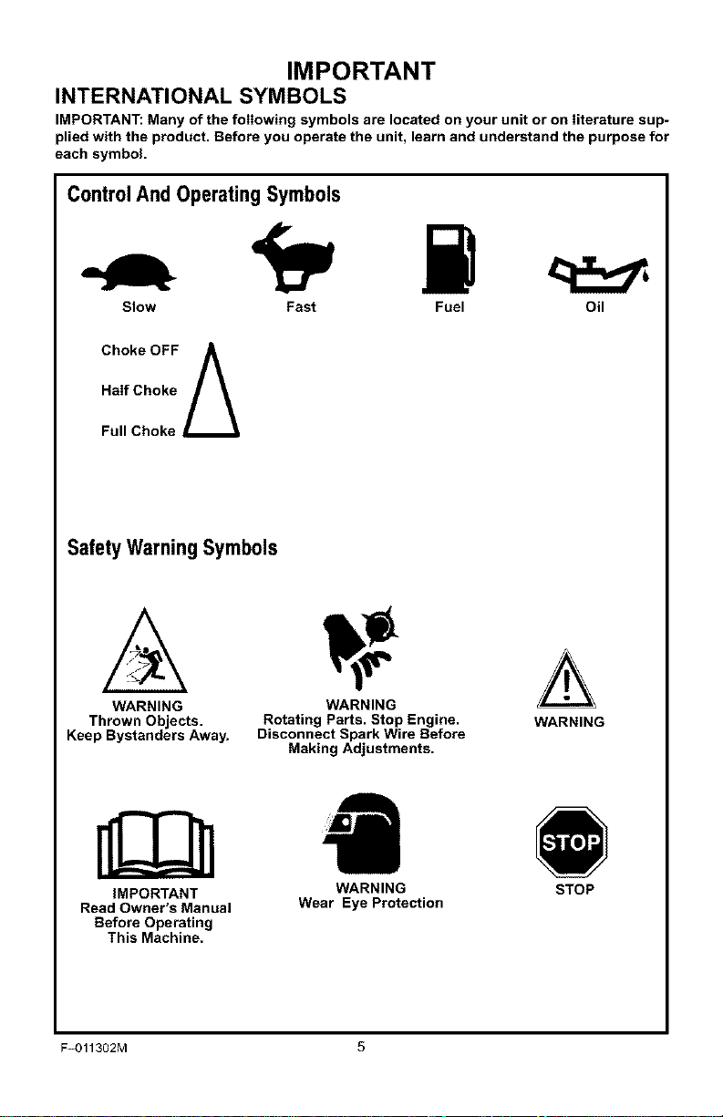
IMPORTANT: Many of the following symbols are located on your unit or on literature sup-
plied with the product. Before you operate the unit, learn and understand the purpose for
each symbol.
ControlAnd Operating Symbols
Slow Fast Fuel Oil
Half Choke
Choke OFF A
Full Choke
Safety Warning Symbols
WARNING WARNING
Thrown Objects. Rotating Parts. Stop Engine. WARNING
Keep Bystanders Away. Disconnect Spark Wire Before
IMPORTANT WARNING STOP
Read Owner's Manual Wear Eye Protection
Before Operating
This Machine.
F-O11302M 5
Making Adjustments.
ASSEMBLY
ASSEMBLY
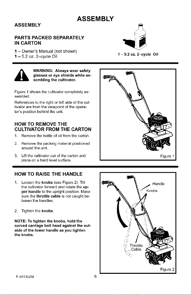
PARTS PACKED SEPARATELY
IN CARTON
1 - Owner's Manual (not shown)
1 - 5.2 oz. 2-cycle Oil
glasses or eye shields while as-
WARNING: Always wear safety
sembling the cultivator.
Figure 1 shows the cultivator completely as-
sembled.
References to the right or left side of the cul-
tivator are from the viewpoint of the opera-
tot's position behind the unit.
HOW TO REMOVE THE
CULTIVATOR FROM THE CARTON
1. Removethe bottle of oil from the carton.
2. Removethe packingmaterial positioned
around the unit.
3. Liftthe cultivator out ofthe carton and
place on a hard level surface.
HOW TO RAISE THE HANDLE
1. Loosen the knobs (see Figure 2). Tilt
the cultivator forward and rotate the up-
per handle to the upright position. Make
sure the throttle cable is not caught be-
tween the handles.
f - 5.2 oz. 2-cycle Oil
Figure 1
2. Tighten the knobs.
NOTE: To tighten the knobs, hold the
curved carriage bolt head against the out-
side of the lower handle as you tighten
the knobs.
F=011302M 6
Figure 2

ASSEMBLY
_." CHECKLIST
For the best performance and satisfaction
from this quality product, please review the
following checklist before you operate the
cultivator:
_' All assembly instructions have been
completed.
_' Check carton. Make sure no loose
parts remain in the carton.
_' All fasteners have been properly tight-
ened.
As you learn how to use the cultivator', pay
extra attention to the foliowing important
items:
_'_" Fuel tank is filled with a fresh, clean,
fuel mixture.
_'_" Become familiar and understand the
function of all controls. Before you
start the engine, operate alI controls.
F-O11302M 7
OPERATION
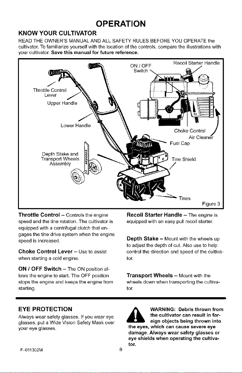
KNOW YOUR CULTIVATOR
READ THE OWNER'S MANUAL AND ALL SAFETY RULES BEFORE YOU OPERATE the
cultivator. To familiarize yourself with the Iocation of the controls, compare the illustrations with
our cultivator'. Save this manual for future reference.
Recoil Starter Handle
/
Throttle Control
Lever
Upper Handle
ON / OFF
Switch
Lower Handle
Assembly_
Throttle Control i Controls the engine
speed and the tine rotation. The cultivator is
equipped with a centrifugal clutch that en-
gages the tine drive system when the engine
speed is increased.
Choke Control Lever - Use to assist
when startinga cold engine.
ON / OFF Switch - The ON position al-
lows the engine to start. The OFF position
stops the engine and keeps the engine from
starting.
Choke Control
Fuel Cap
Tine Shield
Tines
Figure 3
Recoil Starter Handle - The engine is
equipped with an easy pull recoil starter.
Depth Stake - Mount with the wheels up
to adjust the depth of cut. Also use to help
control the direction and speed of the cultiva-
tor.
Transport Wheels i Mountwith the
wheels down whentransporting the cultiva-
tor.
EYE PROTECTION
Always wear safety glasses. If you wear eye
glasses, put a Wide Vision Safety Mask over
your eye glasses.
F-011302M
the cultivator can result in for-
WARNING: Debris thrown from
the eyes, which can cause severe eye
damage. Always wear safety glasses or
eye shields when operating the cultiva-
tor.
eign objects being thrown into

OPERATION
HOW TO USE THE CULTIVATOR
How To Stop The Cultivator
1. Release the throttle control to stop the
tines.
2. Move the ON/OFF switch, on the engine,
to the OFF position.
How To Set The Depth
Use the depth stake to control the tilling
depth and the forward speed. Set the depth
stake to the desired tilling position as fol-
lows:
1. Remove the hairpin and the clevis pin
from the depth stake (see Figure 4).
2. Adjust the depth stake upward to dig
shallower or downward to dig deeper.
Depth Stake
Clevis Pin
Depth Stake
Bracket
3. Reinstall the clevis pin and hairpin.
How To Operate The Cultivator
1. Start the engine.
2. Tilt the unit back on the depth stake until
the tines are offthe ground. Squeeze the
throttle control all the way up against the
hand grip. The engine is governor con-
trolled and must be run at full throttle
while tilling.
3. Hold the handle firmly and slowly tilt the
unit forward to begin the tilling action.
4. As the tines begin to make contact with
the ground, hold back on the handles so
that the tines will dig into the soiI and not
ride forward over the ground.
F-011302M 9
Figure 4
5. Avoid tilling soil that is too dry as it will
pulverize and produce a dust that will not
hold water'. Also, tilling soil that is too wet
will be hard on the machine and produce
unsatisfactory clods.
Lowering the depth stake will slow the
cultivator and make it till deeper. Raising
the depth stake will allow itto move fast-
er and till more shallow. See "Now To
Set The Depth".
_ ARNING: Keep away from the
rotating tines. Rotating tines
can cause injury.
OPERATION
BEFORE STARTING THE ENGINE
How To Prepare The Engine
A WARNING: Always use a safety
_when adding the fuel mixture to
How To Mix The Fuel Mixture
The two cycle engine, used on this cultivator,
requires a mixture of gasoline and oil for lu-
brication of the bearings and other moving
parts. The correct fuel mixture ratio is 24:1
(5.2 oz. oil per one gallon of gas - see the
Fuel Mixture Chart). Gasoline and oil must
be pre-mixed in a clean gasoline container.
Always use fresh, clean, unleaded gasoline.
Mix gasoline and oil as follows:
1. Pour one (1) U.S. quart of fresh, clean,
2. Add 5.3 ounces of clean, high quality,
fuel container. Do not smoke
the engine. When inside an enclosure,
do not fill the fuel tank. Before you add
the fuel mixture, stop the engine. Let the
engine cool for several minutes.
unleaded automotive gasoline into a one
gallon size gasoline container.
two-cycle oil to the gasoline container.
IMPORTANT: Do not use outboard mo-
tor oil or multi-viscosity oils,such as
10W-30 or 10W-40.
install the fuel cap onto the gasoline con-
tainer. Vigorously shake the gasoline
container to mix the oil with the gasoline.
Add an additional three (3) U.S. quarts of
gasoline to the gallon container. Again
shake the gasoline container.
This completes the gasoline mixing pro-
cedure. The gasoline can now be added
to the fuel tank.
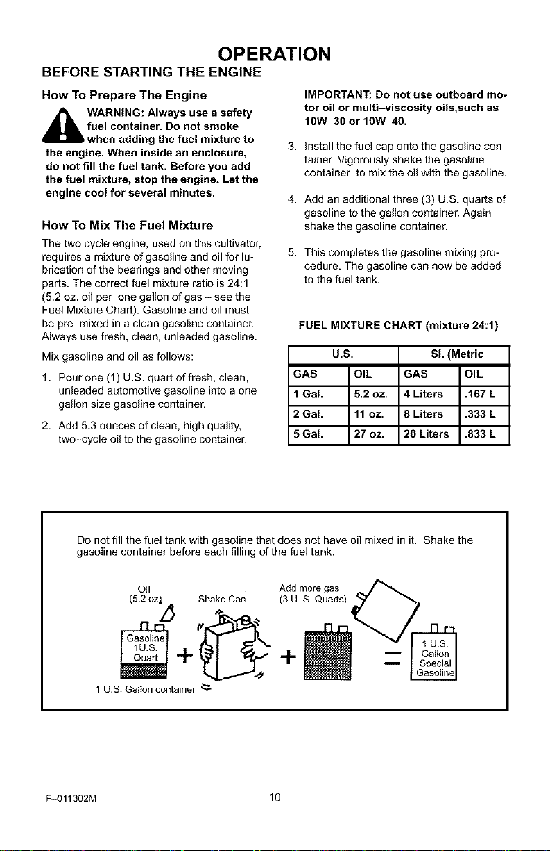
FUEL MIXTURE CHART (mixture 24:1)
U.S. Sl. (Metric
GAS OIL GAS OIL
1 Gal. 5.2 oz. 4 Liters .167 L
2 Gal. 11 oz. 8 Liters .333 L
5 Gal. 27 oz. 20 Liters .833 L
Do not fill the fuel tank with gasoline that does not have oil mixed in it. Shake the
gasoline container before each filling of the fuel tank.
(5.2ozI Shake Can (3 U. S. Quarts)
Ol,
Add more gas
+ +
1 U.S. Gallon container '_
F-011302M 10
OPERATION
HOW TO START THE ENGINE
Before you start the engine, make sure that
you have read and understand all the in-
structions on the preceding pages.
f. Fill the fuel tank to 1/2 inch below the
bottom of the fill neck. Reinstall the fuel
tank cap securely. AIways use fresh fuel.
Never use fuel that could be stale from
iong periods of storage.
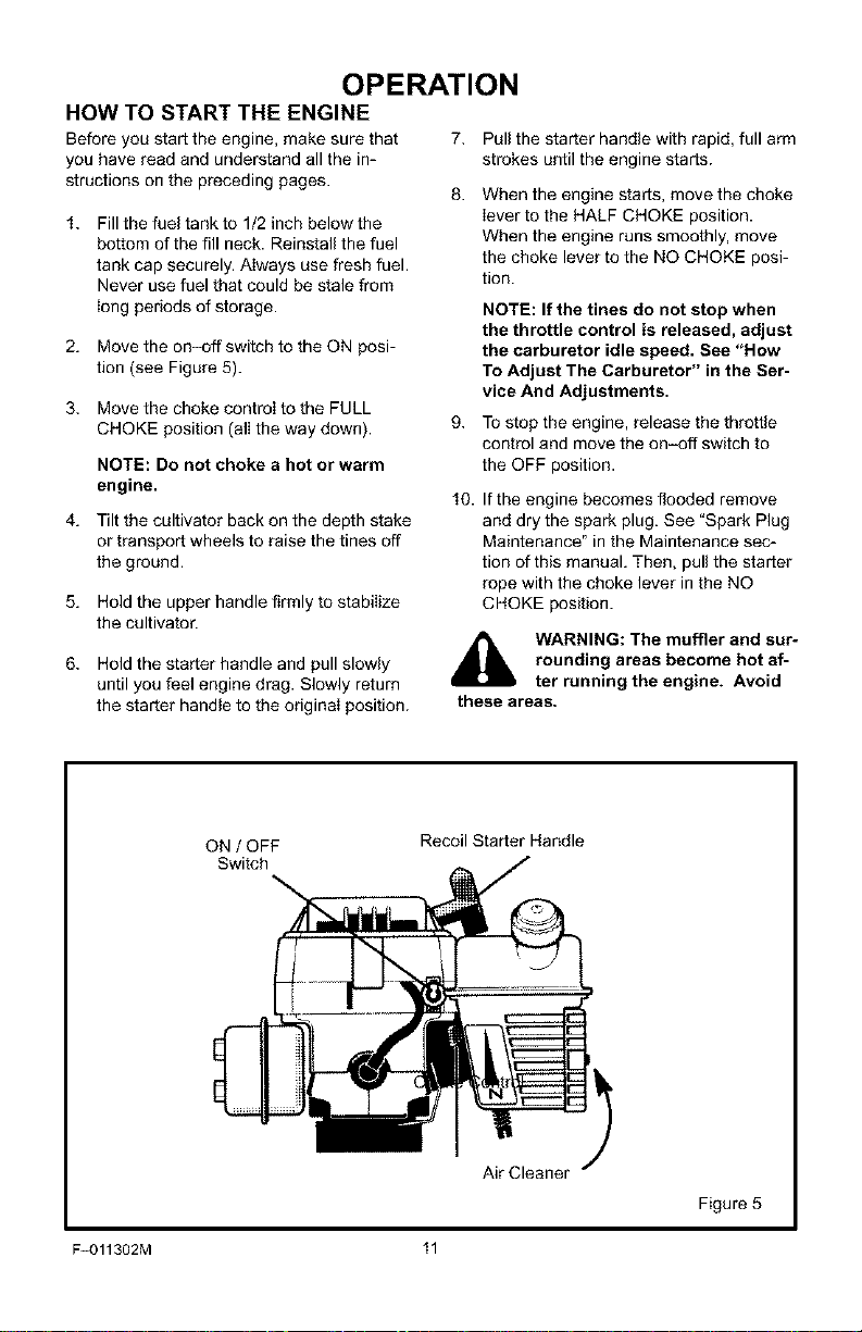
2. Move the on-off switch to the ON posi-
tion (see Figure 5).
3. Move the choke controI to the FULL
CHOKE position (ali the way down).
NOTE: Do not choke a hot or warm
engine.
4. Tilt the cultivator back on the depth stake
or transport wheels to raise the tines off
the ground.
5. Hold the upper handle firmly to stabiIize
the cultivator.
7. Pull the starter handle with rapid, full arm
strokes until the engine starts.
When the engine starts, move the choke
Iever to the HALF CHOKE position.
When the engine runs smoothly, move
the choke lever to the NO CHOKE posi-
tion.
NOTE: If the tines do not stop when
the throttle control is released, adjust
the carburetor idle speed. See "How
To Adjust The Carburetor" in the Ser-
vice And Adjustments.
To stop the engine, release the throttle
control and move the on-off switch to
the OFF position.
10. If the engine becomes flooded remove
and dry the spark plug. See "Spark Plug
Maintenance" in the Maintenance sec-
tion of this manual. Then, pull the starter
rope with the choke lever in the NO
CHOKE position.
6. Hold the starter handle and pull slowly
until you feel engine drag. Slowly return
the starter handle to the original position.
ON / OFF
Switch
F-011302M 11
rounding areas become hot af-
WARNING: The muffler and sur-
these areas.
Recoil Starter Handle
ter running the engine. Avoid
Air Cleaner
Figure 5
CULTIVATING TIPS
Tilling is digging in, turning over and
breaking up packed soil before planting.
Loose unpacked soil helps root growth.
Best tilling depth is 4 to 6 inches. A tiller
wilI also clear the soil of unwanted vege-
tation. The decomposition of this vegeta-
tion matter enriches the soil. Depending
on the climate (rainfall and wind), it may
be advisable to tilI the soil at the end of
the growing season to further condition
the soil.
Avoid tilling soil that is too dry as it will
pulverize and produce a dust that will not
hold water. Also, tilling soil that is too wet
will be hard on the machine and produce
unsatisfactory clods.
Better growth will be obtained if an area
is tilled properly and used soon after till-
ing to preserve the moisture content.
The depth stake (on the back of the culti-
vato o serves a dual purpose. It helps
regulate the depth of the cut and also
acts as a brake to help the operator con-
trol the speed of the cultivator.
Lowering the depth stake will slow the
cultivator and make it till deeper'. Raising
the depth stake will allow it to move fast-
er and till more shallow.
OPERATION
all safety devices and shields in place.
Never allow children or uninstructed
adults to operate cultivator. Shut off en-
gine before unclogging tines or making
repairs. Keep bystanders away from ma-
chine. Keep away from rotating parts
and tines. They can cause injury.
If the cultivator stops forward motion and
tries to dig deeper than necessary, move
the handles from side to side to start for-
ward motion.
Cultivating is loosening or digging
around growing plants which allows the
plants to flourish.
When using the cultivator to remove
weeds, it is best to cultivate no deeper
than 1-1/2 inches. Cultivating deeper will
only pull to the surface ungerminated
weed seeds. Raising the depth stake wilI
allow it to move faster and till more shal-
low.
When cultivating around piants or close
areas, you may want to remove the out-
side tines. See "Tine Replacement" in
the Service/Adjustments section.
manual. Know location and
WARNING: Read the Owner's
functions of all controls. Keep
F-O11302M 12
MAINTENANCE
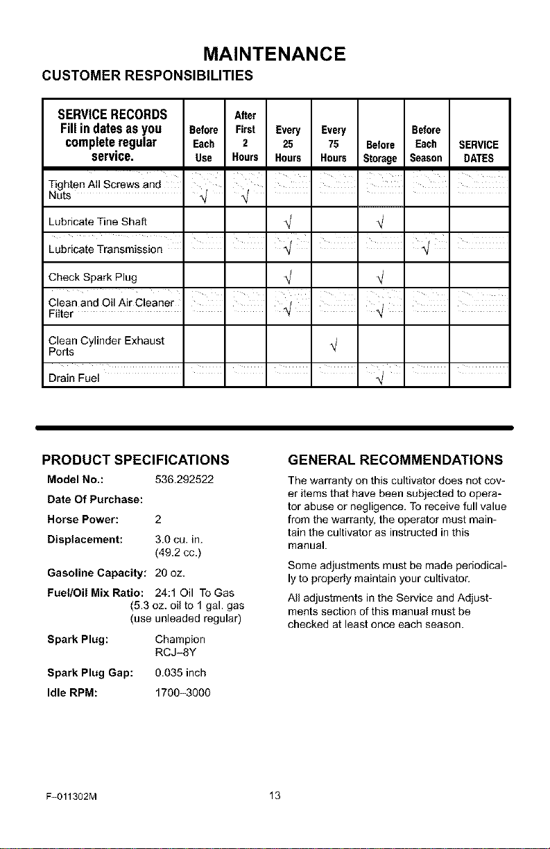
CUSTOMER RESPONSIBILITIES
SERVICE RECORDS After
Fill in dates as you Before First Every Every Before
complete regular Each 2 25 75 Before Each SERVICE
service. Use Hours Hours Hours Storage Season DATES
Tighten Ag Screws and
Nuts
Lubricate Tine Shaft
Lubricate Transmission I I 4 I . '
Check Spark Plug
Clean Cylinder Exhaust
Ports
Drain Fuel " " " " " N/ " "
PRODUCT SPECIFICATIONS
Model No.: 536.292522
Date Of Purchase:
Horse Power: 2
Displacement: 3.0 cu. in.
Gasoline Capacity: 20 oz.
Fuel/Oil Mix Ratio: 24:1 Oil To Gas
Spark Plug: Champion
Spark Plug Gap: 0.035 inch
Idle RPM: 1700-3000
(49.2 cc.)
(5.3 oz. oil to 1 gal. gas
(use unleaded regula o
RCJ-SY
I I I I I I
4 4 ....
i
GENERAL RECOMMENDATIONS
The warranty on this cultivator does not cov-
er items that have been subjected to opera-
tor abuse or negligence. To receive full value
from the warranty, the operator must main-
tain the cultivator as instructed in this
manual.
Some adjustments must be made periodical-
ly to properly maintain your cultivator.
All adjustments in the Service and Adjust-
ments section of this manual must be
checked at least once each season.
F-011302M 13
MAINTENANCE
LUBRICATION
Every 25 hours and/or at the beginning of
each season, make sure the gear box is
filled with lubricant (see Figure 6). Tubes of
gear lubricant are available from most auto-
motive supply stores. Use portable tool
grease such as LubripIate 630AA (Product
No. 06787, 1-3/4 oz. tube) or Lubdplate
GR-132 (Product No. 15892, 10 oz. tube).
After cleaning and before storage, apply oil
to the tine shaft (see Figure 6).
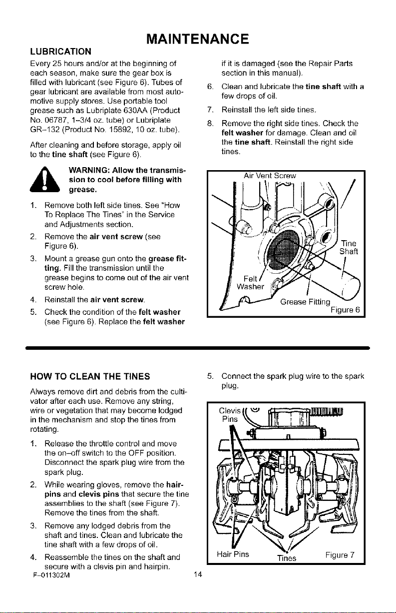
if it is damaged (see the Repair Parts
section in this manual).
6.
Clean and lubricate the tine shaft with a
few drops of oil.
7.
Reinstall the left side tines.
8.
Remove the right side tines. Check the
felt washer for damage. Clean and oil
the tine shaft. Reinstall the right side
tines.
_1_ ARNING: Allow the transmis-
1. Remove both left side tines. See "How
2. Remove the air vent screw (see
3. Mount a grease gun onto the grease fit-
4. Reinstall the air vent screw.
5. Check the condition of the felt washer
sion to cool before filling with
grease.
To Replace The Tines" in the Service
and Adjustments section.
Figure 6).
ting. Fill the transmission until the
grease begins to come out of the air vent
screw hole.
(see Figure 6). Replace the felt washer
HOW TO CLEAN THE TINES
Always remove dirt and debris from the culti-
vator after each use. Remove any string,
wire or vegetation that may become lodged
in the mechanism and stop the tines from
rotating.
1. Release the throttle control and move
the on-off switch to the OFF position.
Disconnect the spark plug wire from the
spark plug.
2. While wearing gloves, remove the hair-
pins and clevis pins that secure the tine
assemblies to the shaft (see Figure 7).
Remove the tines from the shaft.
3. Remove any lodged debris from the
shaft and tines. Clean and lubricate the
fine shaft with a few drops of oil.
4. Reassemble the tines on the shaft and
secure with a clevis pin and hairpin.
F-011302M
Air Vent Screw
Grease Fitting
Figure 6
Connect the spark plug wire to the spark
plug.
Hair Pins Tines Figure 7
14
MAINTENANCE
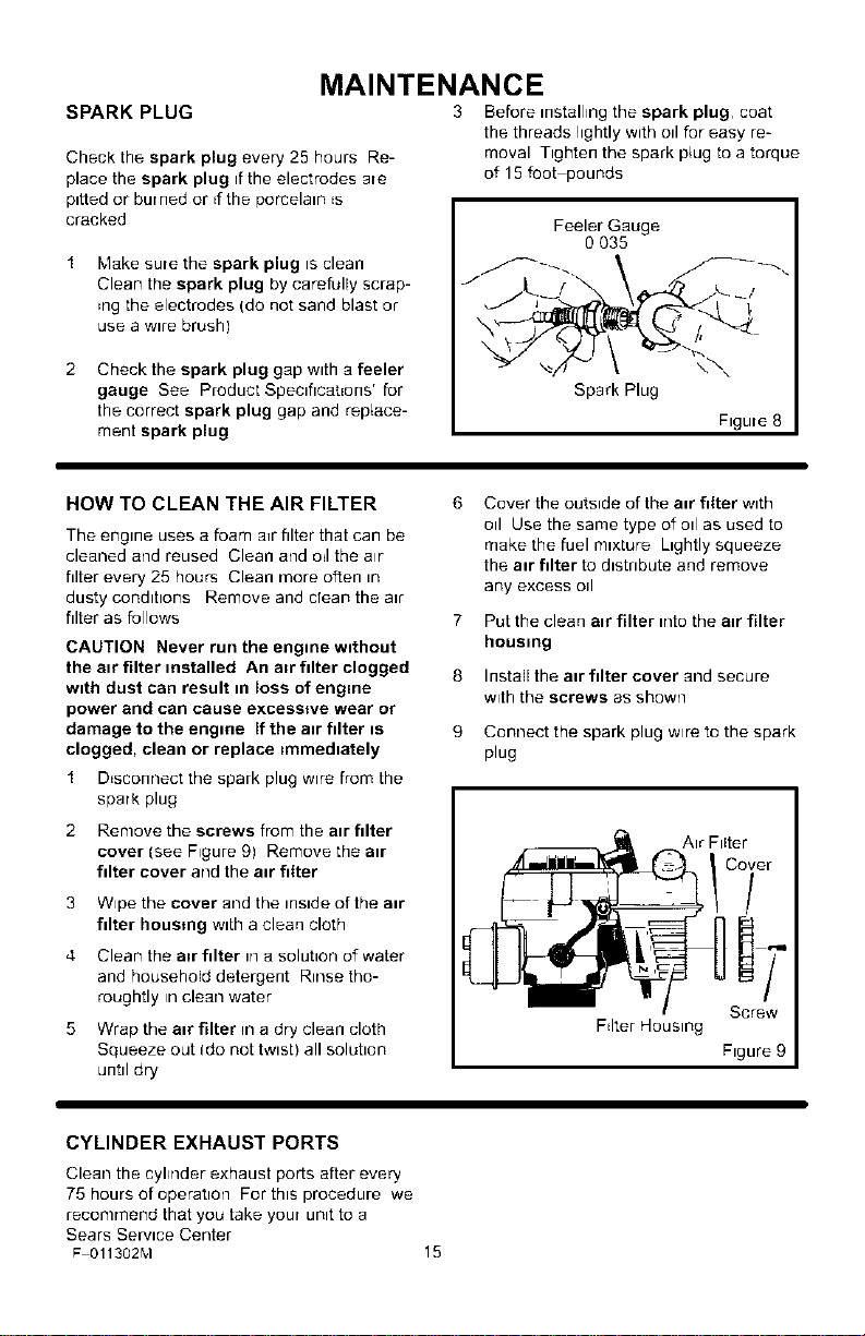
SPARK PLUG
Check the spark plug every 25 hours Re-
place the spark plug if the electrodes are
pitted or bur ned or d the porcelain Es
cracked
Make sure the spark plug is clean
Clean the spark plug by carefully scrap-
Engthe electrodes (do not sand blast or
use a w_re brush)
Check the spark plug gap with a feeler
gauge See Product Speclhcahons r for
the correct spark plug gap and replace-
ment spark plug
3 Before installing the spark plug, coat
the threads lightly with oil for easy re-
moval Tighten the spark plug to a torque
of 15 foot pounds
Feeler Gauge
O 035
Spark Plug
Figure 8
HOW TO CLEAN THE AIR FILTER
The engine uses a foam aTrfilter that can be
cleaned and reused Clean and oEIthe air
filter every 25 hours Clean more often _n
dusty conditions Remove and dean the a_r
filter as follows
CAUTION Never run the engine without
the air filter installed An a=r filter clogged
with dust can result in loss of engine
power and can cause excesmve wear or
damage to the engine If the air filter is
clogged, clean or replace =mmediately
1 DEsconnect the spark plug wire from the
spark plug
2 Remove the screws from the a=r filter
cover (see F=gure 91 Remove the a=r
fdter cover and the a=r filter
3
Wipe the cover and the inside of the air
filter housing with a clean cloth
4
Clean the a=rfdter in a solution of water
and household detergent R_nse tho-
roughtly In clean water
Wrap the air filter .1 a dry clean cloth
Squeeze out (do not twist) all soluhon
untd dry
Cover the outside of the air filter with
oil Use the same type ofo=l as used to
make the fuel m_xture L_ghtly squeeze
the aE filter to d_stnbute and remove
any excess od
7
Put the clean a=r filter .]to the a=r filter
housing
8
Install the air filter cover and secure
with the screws as shown
9
Connect the spark plug wire to the spark
plug
Air Filter
Fdter Housing
Co_er
D:
Screw
Figure 9
CYLINDER EXHAUST PORTS
Clean the cyhder exhaust ports after every
75 hours of operation For this procedure we
recommend that you take your unit to a
Sears Service Center
F 011302M
15
SERVICE AND ADJUSTMENT
HOW TO REMOVE AND INSTALL THE TINES
References to the dght or left side of the cul-
tivator are from the viewpoint of the opera-
tot's position behind the unit.
All four tines are different and cannot be in-
terchanged. The tines must be correctly
installed or the cultivator will not function
propedy.
To till around plants or in small areas, the
outside tines can be removed to reduce the
tilIing width to approximately 7 inches.
sharpening and will become
WARNING: The tines are self
quite sharp from use. Handle
carefully.
The tines will all wear evenly. If the tines are
being replaced because of wear', we recom-
mend that aIIfour tines be replaced at the
same time. To replace the tines, do the fol-
lowing:
Tine Removal
1. Put the on-off switch in the OFF posi-
tion.
2. Disconnect the spark plug wire from the
spark plug.
3. WhiIe wearing gloves, remove the hair-
pins and clevis pins that secure the tine
assemblies to the shaft (see Figure 10).
Remove the tines from one side of the
unit.
Tine Installation
1. Clean and lubricate the tine shaft with a
few drops of oil.
2. Place the inside tine on the tine shaft
and reinstall the clevis pin and hairpin.
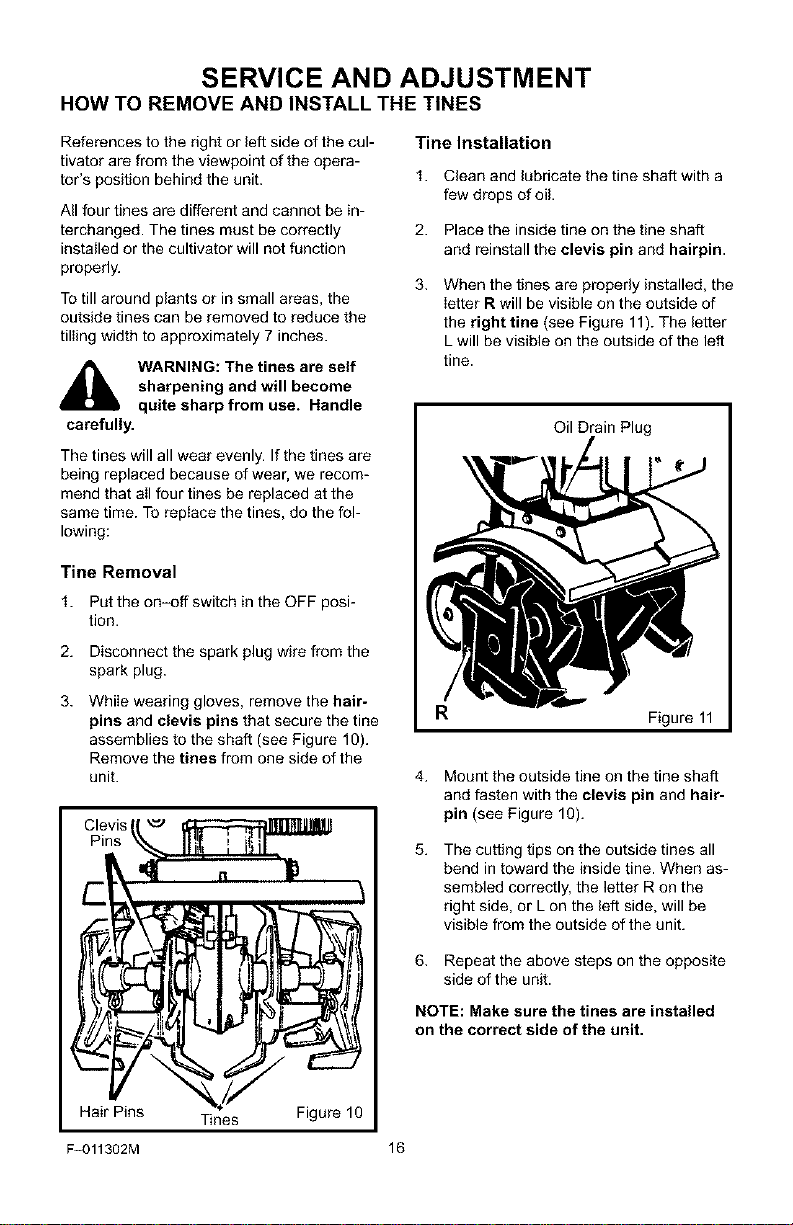
3. When the tines are properly installed, the
letter R will be visible on the outside of
the right tine (see Figure 11). The letter
L will be visible on the outside of the left
tine.
Oil Drain Plug
R Figure 11
4.
Mount the outside tine on the tine shaft
and fasten with the clevis pin and hair-
pin (see Figure 10).
5.
The cutting tips on the outside tines all
bend in toward the inside tine. When as-
sembled correctly, the letter R on the
right side, or L on the left side, will be
visible from the outside of the unit.
Hair Pins Tines Figure 10
F-O11302M 16
6. Repeat the above steps on the opposite
side of the unit.
NOTE: Make sure the tines are installed
on the correct side of the unit.
 Loading...