

Craftsman 536270301 Owner’s Manual
Operator's Manual
CRAFrSMAN°
• Safety
• Operation
Mid-Engine Rider
13.5 HP. Electric Start
30" Mower / Mulcher
Hydrostatic Drive
Model 536.270301
CAUTION: Before using this
product, read this manual
and follow all of its Safety
Rules and Operating
Instructions.
Manual del usario
• Maintenance
• Parts
Tractor cortacesped con motor
situado detras del asiento
Arranque electrico de 13,5 caballos
Cortacesped / trituradora de 76 cm.
Transmision hidrostatica
Modelo 536.270301
PRECAUCION: Antes de usar este
producto, lea este manual y siga
todas las reglas de seguridad e
instrucciones de operaciSn.
Sears, Roebuck and Co., Hoffman Estates, IL. 60179 U.S.A.
F-050610L www.sears.com/craftsman
• Seguridad
• Operacion
• Mantenimiento
• Piezas
TABLE OF CONTENTS
WARRANTY .................................... 2 MAINTENANCE ................................. 21
PRODUCT SPECIFICATIONS ..................... 3 SERVICE AND ADJUSTMENT .................... 27
SAFETY RULES ................................. 4 TROUBLE SHOOTING CHART .................... 36
PREPARATION .................................. 7 SLOPE GUIDE .................................. 38
OPERATION .................................... 10 REPAIR PARTS ................................. 40
LIMITED WARRANTY ON CRAFTSMAN RIDING EQUIPMENT
For two (2) years from the date of purchase, if this Craftsman Riding Equipment is maintained, lubricated and tuned up
according to the instructions in the owner's manual, Sears wilt repair or replace free of charge any parts that are found to be
defective in material or workmanship according to the guidelines of coverage listed below.
Sears will also provide free labor for these applicable warranted parts for the two full years. During the first 30 days of purchase,
there will be no charges to service the product at your home for issues covered by this warranty. (See exclusions below).
For your convenience, IN HOME warranty service will still be available after the first 30 days of purchase, but a trip charge will
apply. This charge will be waived ifthe Craftsman product is dropped off at an authorized Sears location. For the nearest
authorized Sears location, please call 1-800-4-MY-HOME®. This warranty applies only while this product is within the United
States.
This Warranty does not cover:
• Expendable items which become worn during normal use, including but not limited to blades, spark plugs, air cleaners,
belts, and oil filters.
• Standard Maintenance Servicing, oil changes, or tune-ups
• Tire replacement or repair caused by punctures from outside objects, such as nails, thorns, stumps or glass.
• Repairs necessary because of operator abuse, including but not limited to, damage caused by towing objects beyond the
capability of the riding equipment, impacting objects that bend the frame or crankshaft, or over-speeding the engine.
• Repairs necessary because of operator negligence, including but not limited to, electrical and mechanical damage caused
by improper storage, failure to use the proper grade and amount of engine oil, failure to keep the deck clear of flammable
debris, or failure to maintain the equipment according to the instructions contained in the owner's manual.
• Engine (fuel system) cleaning or repairs caused by fuel determined to be contaminated or oxidized (stale). In general, fuel
should be used within 30 days of its purchase date.
• Normal deterioration and wear of the exterior finishes, or product label replacement.
• Riding equipment used for commercial or rental purposes.
LIMITED WARRANTY ON BATTERY
For ninety (90) days from date of purchase, if any battery included with this riding equipment proves defective in material or
workmanship and our testing determines the battery will not hold a charge, Sears will replace the battery at no charge. During
the first 30 days of purchase, there will be no charges to replace the battery at your home. After the first 30 days, for your conve-
nience, IN-HOME warranty service will still be available but a trip charge will apply. This charge will be waived if the Craftsman
product is dropped off at an authorized Sears location. For the nearest authorized Sears location, please call 1-800-4-MY-
HOME®. This Warranty applies only while this product is within the United States. This warranty gives you specific legal rights,
and you may also have other rights, which vary, from state to state.
Sears, Roebuck and Co., Dept. 817WA, Hoffman Estates, IL 60179
F-O50610L 2
Congratulations on your purchase of a Craftsman Mid-Engine
Rider. It has been designed, engineered and manufactured to
give you the best possible dependability and performance.
If you experience any problems you cannot easily remedy, please
see your nearest Sears Service Center. We have competent, well
trained technicians and the proper tools to service or repair this
unit.
Please read and keep this manual. The instructions will enable
you to assemble and maintain your unit properly. Always observe
the "Safety Rules".
Craftsman Mid-Engine Rider
Record in the space below the serial number and the date
of purchase of this unit.
The model number and serial number are found on a decal
attached to the unit.
Model Number: 536.270301
Serial Number:
PRODUCT SPECIFICATIONS
Engine .................. 13.5 HR
Bore .................. 3.44 in. (87.31 mm)
Stroke ................ 3.06 in. (77.78 mm)
Displacement ......... 28.42 cu. in. (466 cc)
Armature air gap ...... 0.010-0.014 in. (0.25-0.36 mm)
Valve Clearance with valve springs installed and piston
0.25 in. (6 mm) past top dead center (check when engine
is cold)
Intake ................. 0.003-0.005 in. (0.08-0.13 mm)
Exhaust ............... 0.005-0.007 in. (0.13-0.18 mm)
Charging System ......... 3 amperes at 3600 rpm
Fuel Tank Size ........... 1.1 gallon
Type of Fuel ............. Unleaded Regular
Oil Capacity .............. 48 ounces (3 pints)
Oil Type ................. Above 32 degrees SAE 30
.......................... Below 32 degrees SAE 5W30
Spark Plug (Gap 0.030") .. Champion RJ4C
Tire Air Pressure ......... Front 22 psi (See tire sidewall)
Tire Air Pressure ......... Rear 14 psi (See tire sidewall)
Drive System ............ Hydrostatic
Ground Speed Range ..... Forward 5.0 mph
.......................... Reverse 2.5 mph
Tilt Seat ................. Access to engine and battery.
Mower Housing .......... Floating suspension, one blade.
Cutting Height ........... 6 positions from 11/2to 4 inches.
Blade Nut Torque ......... 30 foot-pounds (ft-lbs)
Power Ratings: The power ratings for an individual engine mod-
el are initially developed by starting with SAE (Society of Automo-
tive Engineers) code J1940 (Small Engine Power & Torque
Rating Procedure) (Revision 2002-05). Given both the wide array
of products on which our engines are placed, and the variety of
environmental issues applicable to operating the equipment, it
may be that the engine you have purchased will not develop the
rated horsepower when used in a piece of power equipment (ac-
tual "on-site" power). This difference is due to a variety of factors
including, but not limited to, the following: differences in altitude,
temperature, barometric pressure, humidity, fuel, engine lubrica-
tion, maximum governed engine speed, individual engine to en-
gine variability, design of the particular piece of power equipment,
the manner in which the engine is operated, engine run-in to re-
duce friction and clean out of combustion chambers, adjustments
to the valves and carburetor, and other factors. The power ratings
may also be adjusted based on comparisons to other similar en-
gines utilized in similar applications, and will therefore not neces-
sarily match the values derived using the foregoing codes.
NOTE: Actual sustained horsepower will likely be lower due
to operating limitations and environmental factors.
F-050610L
Date of Purchase:
Keep these numbers for future reference.
REPAIR PROTECTION AGREEMENT
A Repair Protection Agreement is available on this unit. See the
nearest Sears Store for information.
Engine Exhaust, some of its constituents, and
certain vehicle components contain or emit
chemicals known to the State of California to
cause cancer and birth defects or other repro-
ductive harm,
Battery posts, terminals and related accesso-
ries contain lead and lead compounds, chemi-
cals known to the State of California to cause
cancer and birth defects or other reproductive
harm. WASH HANDS AFTER HANDLING.
NOTE: This unit is equipped with an internal combustion engine
and must not be used on or near any unimproved forest-covered,
brush-covered or grass-covered land unless the engine's exhaust
system is equipped with a spark arrester meeting applicable local
or state laws (if any). If a spark arrester is used, it must be
maintained in effective working order by the operator.
In the State of California, the above is required by law (Section
4442 of the California Public Resources Code). Other states may
have similar laws. Federal laws apply on federal lands. See a
Sears Service Center for a spark arrester for the muffler.
In some areas, local law requires the use of a resistor spark plug
to control the ignition signals. See a Sears Service Center for a
resistor spark plug for the engine.
In the state of California, Model Series 280000 engines are certi-
fied by the California Air Resources Board to meet emissions
standards for 125 hours. Such certification does not grant the
purchaser, owner or operator of this engine any additional war-
ranties with respect to the performance or operational life of this
engine. This engine is warranted solely according to the product
and emissions warranties stated elsewhere in this manual.
SAFETY RULES
Safe Operation Practices for Ride-on Mowers
,_ WARNING: This cutting machine is capable of amputating hands and feet and throwing objects. Failure to observe the
L
1.
2. Only allow responsible adults, who are familiar with the instruc-
3. Clear the area of objects such as rocks, toys, wire, etc., which
4. Be sure the area is clear of other people before mowing. Stop
5. Never carry passengers.
6. Turn off power to the blades or any attachments before backing
7. Be aware of the mower discharge direction and do not point it
8. Slow down before turning.
9. Never leave a machine unattended with the engine running. Al-
10. Turn off power to attachment(s) when transporting or not in use.
11. Stop the engine before removing the grass bagger or unclog-
12. Mow only in daylight or good artificial light.
13. Do not operate the machine while under the influence of alcohol
14. Watch for traffic when operating near or crossing roadways.
15. Use extra caution when loading or unloading the machine into
16.
17.
18.
19.
20.
F-050610L 4
following safety instructions could result in serious injury or death.
General operation
Read, understand and follow all instructions in the Instruction
Book, on the machine, the engine and with any attachments be-
fore starting.
tions, to operate the machine.
could be picked up and thrown by the blade.
the machine if anyone enters the area.
up. Do not mow in reverse unless absolutely necessary. Always
look down and behind before and while backing.
at anyone. Do not operate the mower without either the entire
grass bagger or the mower guard in place.
ways turn off the blade(s), set the parking brake, stop the en-
gine and remove the key before dismounting.
Turn off the blade(s) when not mowing.
ging the chute.
or drugs or when very tired.
a trailer or truck.
Disengage all attachment clutches and shift into Neutral before
attempting to start the engine.
Always wear goggles, safety glasses, or an eye shield when
you operate the unit to protect your eyes from foreign objects
that can be thrown from the unit. Always wear eye protection
when you make an adjustment or repair to the machine.
Use care when pulling loads or using heavy equipment.
a. Use only approved drawbar hitch points.
b. Limit loads to those you can safely control.
c. Do not turn sharply. Use care when backing.
d. Use counterweights or wheel weights when suggested in the
Instruction Book.
Do not operate this machine if you are taking drugs or other me-
dication which can cause drowsiness or affect your ability to op-
erate this machine.
Do not use this machine if you are mentally or physically unable
to operate this machine safely.
21. Data indicates that operators, age 60 years and above, are in-
volved in a large percentage of riding mower related injuries.
These operators should evaluate their ability to operate a riding
mower safely enough to protect themselves and others from
serious injury.
II. Slope operation
Slopes and rough terrain are major factors related to loss-of-
control and tip-over accidents, which can result in severe inju-
ry or death. ALL slopes require extra caution. If you cannot
back up the slope or if you feel uneasy on the slope, do not mow
it. See the "Slope Guide" in the back of this book to check for
safe operation.
DO
1. Mow up and down slopes, not across.
2. Remove obstacles such as rocks, limbs, etc...
3. Watch for holes, ruts or bumps. Uneven terrain could overturn
the machine. Tallgrass can hide obstacles.
4. Follow the manufacturer's recommendations for wheel weights
or counterweights to improve stability.
5. Use extra care with grass baggers or other attachments, they
can change the stability of the machine.
6. Keep all movement on the slopes slow and gradual. Do not
make sudden changes in speed or direction.
7. Avoid starting or stopping on a slope. If tires lose traction, turn
off the blades and proceed slowly straight down the slope.
DO NOT
1. Do not turn on slopes unless absolutely necessary, then only
turn slowly and gradually downhill, if possible.
2. Do not mow drop-offs, ditches or embankments. A wheel over
the edge or an edge caving in could cause a sudden overturn
and an injury or death.
3. Do not mow on wet grass. Reduced traction could cause slid-
ing.
4. Do not try to stabilize the machine by putting your foot on the
ground.
5. Do not use a grass bagger or other rear mounted accessories
on steep slopes (greater than 10 degrees).
III. Children
Tragic accidents can occur if the operator is not alert to the
presence of children. Children are often attracted to the ma-
chine and the mowing activity. NEVER assume that children
will remain where you last saw them.
1. Keep children out of the mowing area and in the watchful care
of another responsible adult.
2. Be alert and turn the engine off if children enter the area.
3. Before and when backing, look behind and down for small
children.
SAFETY RULES
4. Never carry children or any passengers, even with the blades 5.
off. They may fall off and be seriously injured or interfere with
the safe operation of the machine.
5.
Never allow children to operate the machine. Instruct children
in the potential dangers of the machine. 6.
6.
Use extra care when approaching blind corners, shrubs, trees
or other objects that may obscure vision. 7.
IV. Service
1. Use extra care when handling gasoline and other fuels. Fuels
are flammable and the vapors are explosive.
a. Use only an approved container.
b. Never remove the gas cap or add fuel with the engine run-
ning. Allow the engine to cool for several minutes before
refueling. Do not smoke.
c. Never refuel the machine indoors or near appliances with
pilot lights, heaters, or other ignition sources.
d. Never store the machine with fuel in the tank or fuel con-
tainer inside where there is an open flame, such as a water
heater.
2. Never start or run the engine insidea closed area.
a. Make sure that spark plug, muffler, fuel cap and air cleaner
are in place.
b. Do not crank engine with spark plug removed.
c. If fuel spills, wait until itevaporates before starting engine.
d. Do not start ifthere is LP or natural gas leakage inthe area.
3. Keep all nuts and bolts, especially the blade attachment nuts
tight. Frequently check the blade(s) for wear or damage such
as cracks and nicks. A blade that is bent or damaged must be
immediately replaced with an original equipment blade from an
authorized service dealer. For safety, replace the blade every
two years. Keep the equipment in good condition.
4. Never tamper with the safety devices. Check their proper oper-
ation regularly.
To reduce fire hazards, keep the machine free of grass, leaves
or other debris build-up. Clean up oil or fuel spills. Allow the ma-
chine to cool before storing.
a. Allow muffler and engine areas to cool before touching.
Stop and inspect the equipment if you strike an object. Repair,
if necessary, before restarting.
Never make adjustments or repairs with the engine running.
The carburetor can be adjusted with the engine running. Do not
change the engine governor settings or over-speed the en-
gine.
8.
Grass bagger components are subject to wear, damage and
deterioration, which could expose moving parts or allow objects
to be thrown. For storage, always make sure the grass bag is
empty. Frequently check components and replace with man-
ufacturer's recommended parts when necessary.
9.
Mower blade(s) are sharp and can cut. Wrap the blade(s) or
wear gloves and use extra caution when servicing them or the
blade housing area.
10.
Check the brake operation frequently. Adjust and service as re-
quired.
11.
Wait for all movement to stop before servicing any part of the
unit.
RESPONSIBILITY OF THE OWNER
Environmental Awareness
• Do not fill the engine's fuel tank completely full.
• Drain fuel for off-season storage.
• Use only unleaded gasoline.
• Service the air cleaner regularly.
• Change oil regularly. Use oil rated 30 in the summer.
• Tune-up the engine regularly.
• Keep equipment in efficient operating condition.
• Dispose of used engine oil properly.
The safety symbol _ is used to identify safety information about hazards that can result in personal injury. A signal
word (DANGER, WARNING, or CAUTION) is used with the alert symbol to indicate the likelihood and the potential
severity of injury. In addition, a hazard symbol may be used to represent the type of hazard.
DANGER indicates a hazard which, if not avoided, will result in death or serious injury.
WARNING indicates a hazard which, if not avoided, could result in death or serious injury.
CAUTION indicates a hazard which, if not avoided, might result in minor or moderate injury.
CAUTION when used without the alert symbol, indicates a situation that could result in damage to the engine.
F-050610L 5
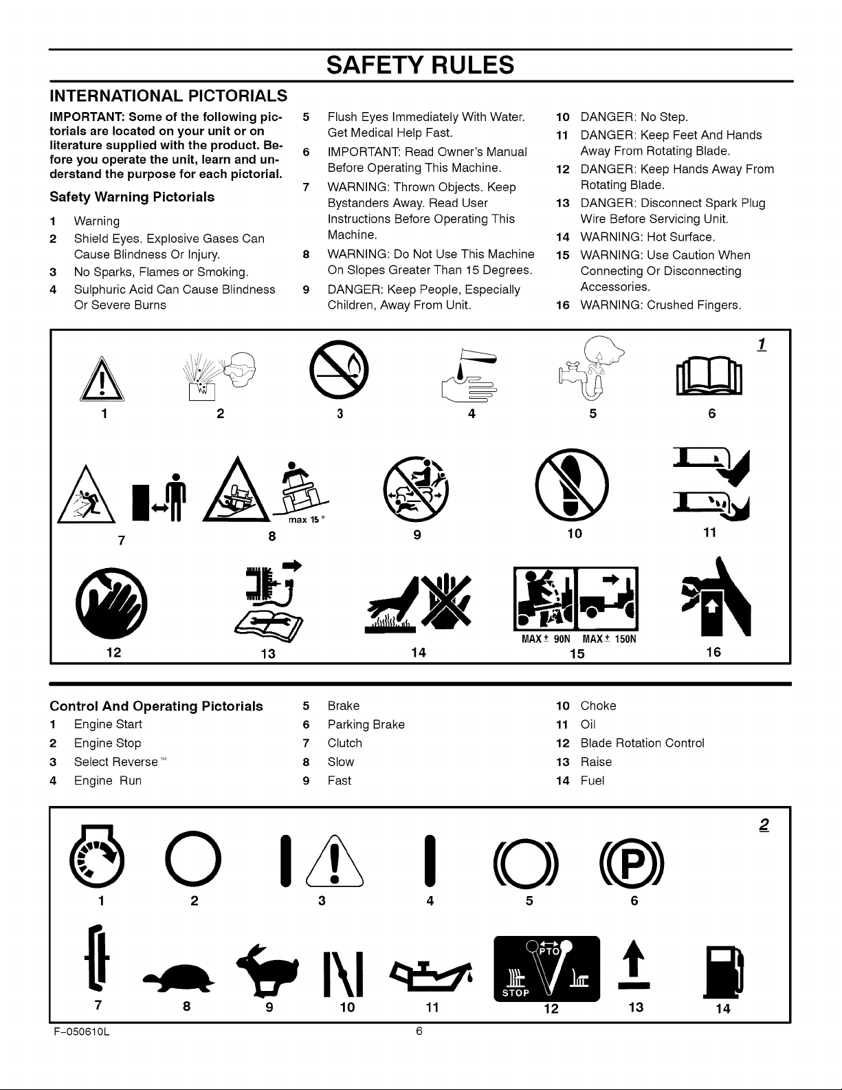
INTERNATIONAL PICTORIALS
IMPORTANT: Some of the following pic-
torials are located on your unit or on
literature supplied with the product. Be-
fore you operate the unit, learn and un-
derstand the purpose for each pictorial.
Safety Warning Pictorials
1 Warning
2 Shield Eyes. Explosive Gases Can
Cause Blindness Or Injury.
3 No Sparks, Flames or Smoking.
4 8ulphuric Acid Can Cause Blindness
Or Severe Burns
SAFETY RULES
5 Flush Eyes Immediately With Water.
Get Medical Help Fast.
6 IMPORTANT: Read Owner's Manual
Before Operating This Machine.
7 WARNING: Thrown Objects. Keep
Bystanders Away. Read User
Instructions Before Operating This
Machine.
8 WARNING: Do Not Use This Machine
On Slopes Greater Than 15 Degrees.
9 DANGER: Keep People, Especially
Children, Away From Unit.
@
10 DANGER: No Step.
11 DANGER: Keep Feet And Hands
Away From Rotating Blade.
12 DANGER: Keep Hands Away From
Rotating Blade.
13 DANGER: Disconnect Spark Plug
Wire Before Servicing Unit.
14 WARNING: Hot Surface.
15 WARNING: Use Caution When
Connecting Or Disconnecting
Accessories.
16 WARNING: Crushed Fingers.
_/
6
A Ab
7 8
12
Control And Operating Pictorials
1 Engine Start
2 Engine Stop
3 Select Reverse ,M
4 Engine Run
13
9 10 11
MAX±90N MAX±150N
14 15 16
5 Brake 10 Choke
6 Parking Brake 11 Oil
7 Clutch 12 Blade Rotation Control
8 Slow 13 Raise
9 Fast 14 Fuel
I O
3
4
2_
7
F-050610L 6
9 10 11 12 13 14
t
PREPARATION
PREPARATION
Read and follow the preparation instructions for your mower. All
fasteners are in the parts bag. Do not discard any parts or material
until the unit is assembled.
NOTE: In this instruction book, left and right describe the loca-
tion of a part from the viewpoint of someone setting in the oper-
ator's seat.
_ WARNING: Before doing any preparation or mainte-
HOW TO REMOVE FROM THE CARTON
To remove the unit from the carton, follow the instructions below.
nance to the mower, remove the wire from the spark
plug.
1. Locate the two tear tabs at the top of the carton.
2. Pull the tear tape no more than twelve inchesat a time.
3. Re-grasp the tear tape next to the carton and pull again.
4. One the tear tape has been completely removed from both
ends, remove the top wood and set aside.
5. Repeat the process on the tear tabs at the bottom of the carton.
6. Set the panels aside.
7. Move the shift lever to the neutral (N) position.
NOTE: See the Operation section, page 10, for the location
of the controls,
8. If the parking brake is engaged, completely depress the
clutch/brake pedal to release the brake.
9. Move the lift lever to the highest position.
CAUTION: Check the bottom of the carton for staples,
Remove any staples that are in the path of the tires,
10. Remove the mower from the shipping skid.
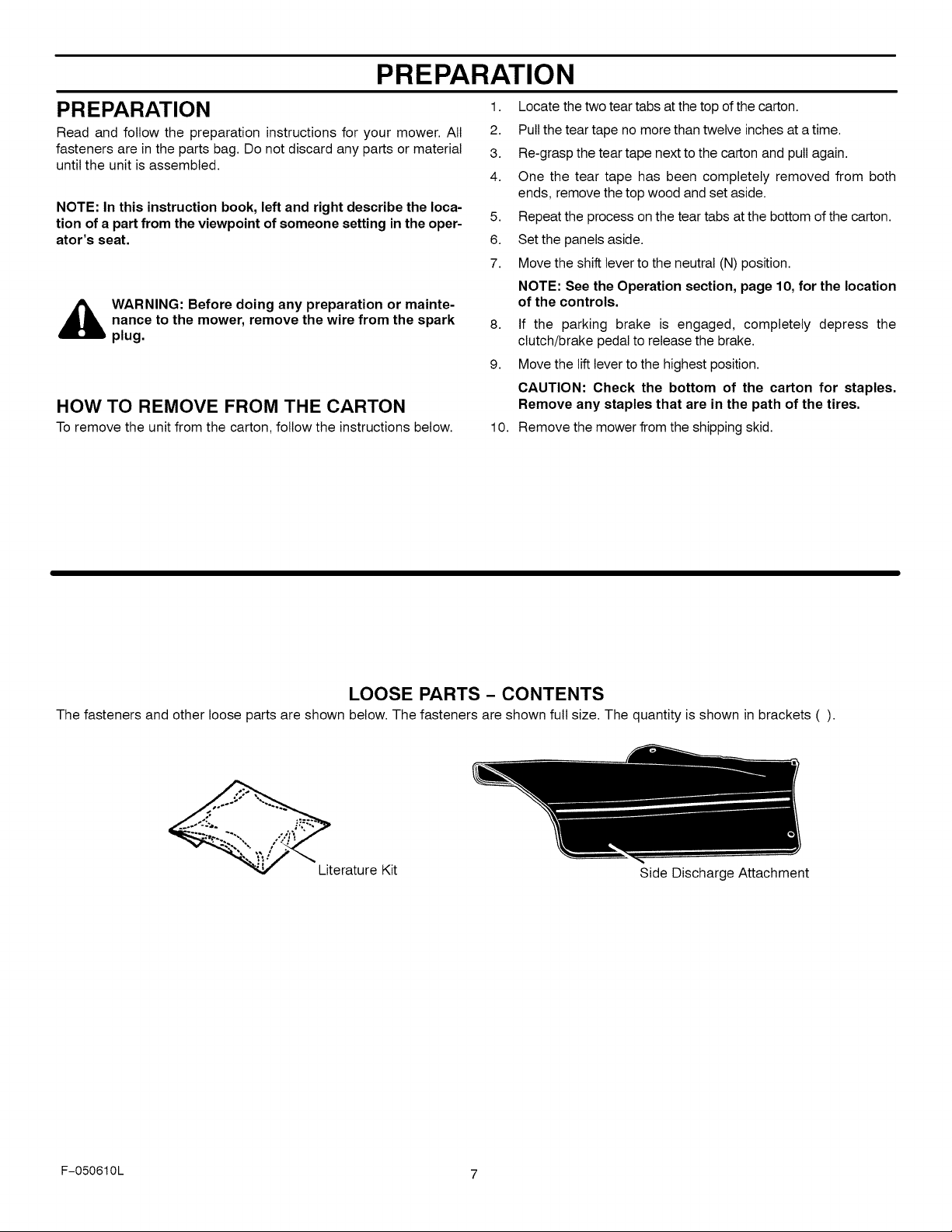
LOOSE PARTS - CONTENTS
The fasteners and other loose parts are shown below. The fasteners are shown full size. The quantity is shown in brackets ().
Literature Kit
Side Discharge Attachment
F-050610L 7
PREPARATION
MAINTENANCE FREE BATTERY 3. Remove the protective cap from the battery terminal.
4.
IMPORTANT: Before you attach the battery cables to the
battery, check the battery date. The battery date tells if the
battery must be charged.
1. Raise the seat support and secure in the UP position with the
seat support rod.
2. Check the top and the side of the battery for the location of the
battery date (Figure 1).
3. If the battery is put into service before the battery date, the
battery cables can be attached without charging the battery.
See "How To Install The Battery Cables".
4. If the battery is put into service after the battery date, the
battery must be charged. See "How To Charge The
Maintenance Free Battery".
HOW TO CHARGE
THE MAINTENANCE FREE BATTERY
,_ WARNING: When you charge the battery, do not
1. To disconnect the battery retainer from the battery tray, push
2. Remove the battery from the right side of the unit.
smoke. Keep the battery away from any sparks. The
fumes from the battery acid can cause an explosion.
in on the lower end of the battery retainer.
Use a 12 volt battery charger to charge the battery. Charge at
a rate of 6 amperes for one hour. If you do not have a battery
charger, have an authorized service center charge the battery.
5.
Install the battery and secure with the battery retainer. Make
sure the positive (+) terminal is on the right side.
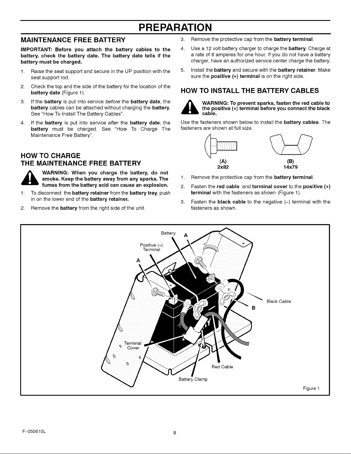
HOW TO INSTALL THE BATTERY CABLES
,_ WARNING: To prevent sparks, fasten the red cable to
Use the fasteners shown below to install the battery cables. The
fasteners are shown at full size.
1.
2.
3.
the positive (+) terminal before you connect the black
cable.
(A)
2x82
Remove the protective cap from the battery terminal.
Fasten the red cable and terminal cover to the positive (+)
terminal with the fasteners as shown (Figure 1).
Fasten the black cable to the negative (-) terminal with the
fasteners as shown.
(B)
14x79
Positive (+)
Terminal
A
Battery A
Black Cable
B
Red Cable
Battery Clamp
Figure 1
F-050610L 8
PREPARATION
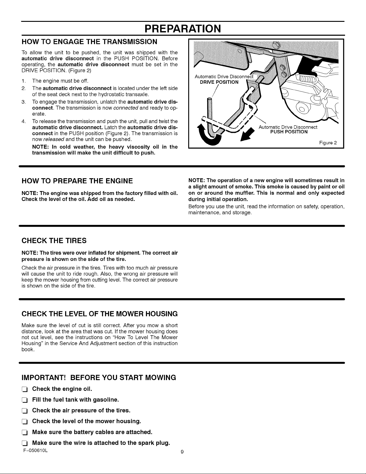
HOW TO ENGAGE THE TRANSMISSION
To allow the unit to be pushed, the unit was shipped with the
automatic drive disconnect in the PUSH POSITION. Before
operating, the automatic drive disconnect must be set in the
DRIVE POSITION. (Figure 2)
1. The engine must be off.
2. The automatic drive disconnect is located under the left side
of the seat deck next to the hydrostatic transaxle.
3. To engage the transmission, unlatch the automatic drive dis-
connect. The transmission is now connected and ready to op-
erate.
4. To release the transmission and push the unit, pull and twist the
automatic drive disconnect, Latch the automatic drive dis-
connect in the PUSH position (Figure 2). The transmission is
now released and the unit can be pushed.
NOTE: In cold weather, the heavy viscosity oil in the
transmission will make the unit difficult to push,
Automatic Drive Disconnect
DRIVEPOSITION
/
Automatic Drive Disconnect
PUSH POSITION
Figure 2
HOW TO PREPARE THE ENGINE
NOTE: The engine was shipped from the factory filled with oil.
Check the level of the oil. Add oil as needed.
CHECK THE TIRES
NOTE: The tires were over inflated for shipment. The correct air
pressure is shown on the side of the tire.
Check the air pressure in the tires. Tires with too much air pressure
will cause the unit to ride rough. Also, the wrong air pressure will
keep the mower housing from cutting level. The correct air pressure
is shown on the side of the tire.
CHECK THE LEVEL OF THE MOWER HOUSING
Make sure the level of cut is still correct. After you mow a short
distance, look at the area that was cut. If the mower housing does
not cut level, see the instructions on "How To Level The Mower
Housing" in the Service And Adjustment section of this instruction
book.
NOTE: The operation of a new engine will sometimes result in
a slight amount of smoke. This smoke is caused by paint or oil
on or around the muffler. This is normal and only expected
during initial operation.
Before you use the unit, read the information on safety, operation,
maintenance, and storage.
IMPORTANT! BEFORE YOU START MOWING
[] Check the engine oil.
[] Fill the fuel tank with gasoline.
[] Check the air pressure of the tires.
[] Check the level of the mower housing.
[] Make sure the battery cables are attached.
[] Make sure the wire is attached to the spark plug.
F-050610L
OPERATION
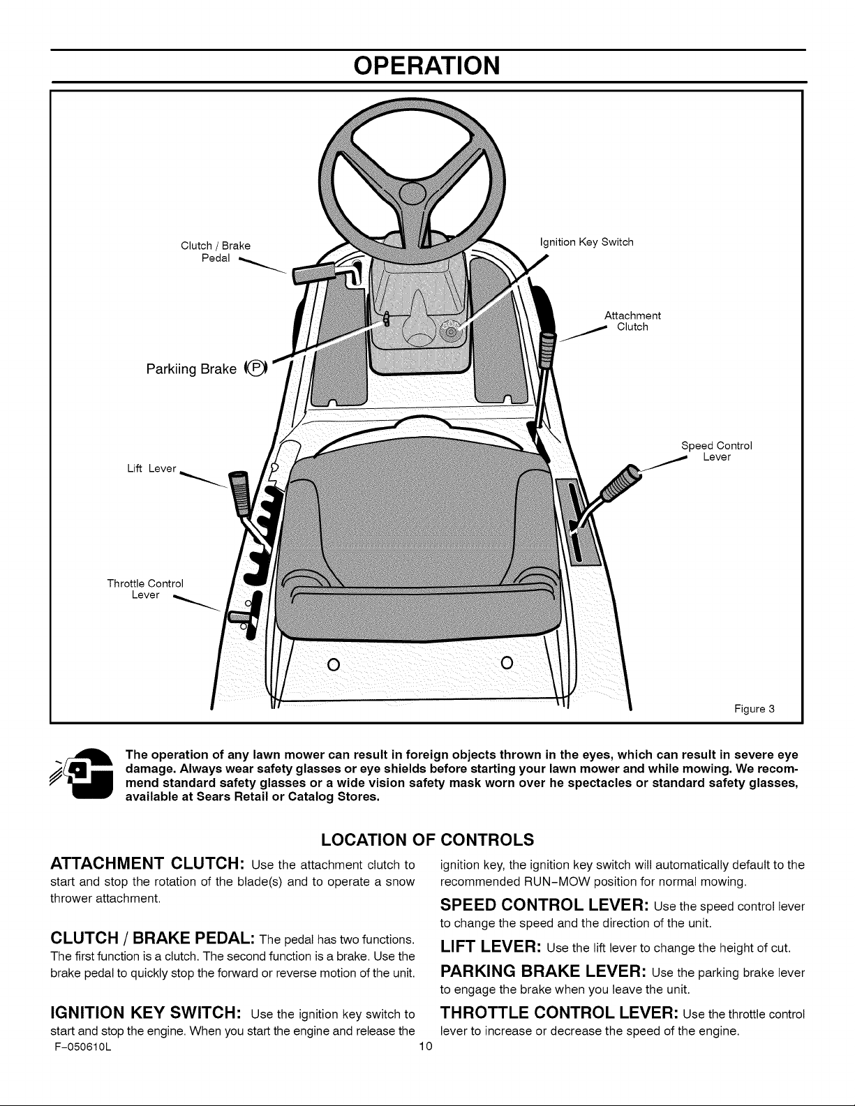
Parkiing Brake
Lift Lever
Throttle Control
Lever
Clutch / Brake
Pedal
Ignition Key Switch
Attachment
Clutch
Speed Control
Lever
The operation of any lawn mower can result in foreign objects thrown in the eyes, which can result in severe eye
damage. Always wear safety glasses or eye shields before starting your lawn mower and while mowing. We recom-
mend standard safety glasses or a wide vision safety mask worn over he spectacles or standard safety glasses,
available at Sears Retail or Catalog Stores.
LOCATION OF CONTROLS
ATTACHMENT CLUTCH: Use the attachment clutch to
start and stop the rotation of the blade(s) and to operate a snow
thrower attachment.
CLUTCH / BRAKE PEDAL: The pedal has two functions.
The first function is a clutch. The second function is a brake. Use the
brake pedal to quickly stop the forward or reverse motion ofthe unit.
IGNITION KEY SWITCH: Use the ignition key switch to
start and stop the engine. When you start the engine and release the
F-050610L 10
Figure 3
ignition key, the ignition key switch will automatically default to the
recommended RUN-MOW position for normal mowing.
SPEED CONTROL LEVER: Usethe speed control lever
to change the speed and the direction of the unit.
LIFT LEVER: Use the lift lever to change the height of cut.
PARKING BRAKE LEVER: Usethe parking brake lever
to engage the brake when you leave the unit.
THROTTLE CONTROL LEVER: Usethe throttle control
lever to increase or decrease the speed of the engine.
ATTACHMENTS
OPERATION
This unit can use many different attachments. See the attachment
page in this book. This unit can pull attachments like a lawn
sweeper, a lawn aerator, a hopper spreader, or a small trailer. This
unit can not use attachments that engage the ground like a plow, a
disk harrow, or a cultivator.
For all pull-behind attachments or trailers, the maximum gross
ELECTRICAL SAFETY SYSTEM
The electrical system has two primary components, an Operator
Presence System and a Select Reverse ,Msystem.
Operator Presence System (Seat)
The seat has an Operator Presence System to shut off the engine
when the operator leaves the seat. This system is not intended for
weight is 200 pounds. Gross weight is the weight of the attachment
or trailer and any load that might be on or in it.
Do not operate on a slope that is greater than 10 degrees when
using a pull-behind attachment or trailer. We have included a slope
guide in this book to help you determine the slope on which you will
be operating your unit. Never allow someone to stand or ride on or
in an attachment or trailer.
regular use in stopping the engine or the blade(s). Before leaving the
seat, move the blade rotation control to the DISENGAGE position,
shift to neutral, set the parking brake and stop the engine.
Select Reverse TM System
The Select Reverse 'M system will allow the mower blade(s) to
continue to rotate when traveling in reverse. See "How To Operate
The Ignition Key Switch" and "How To Start The Engine" for further
details.
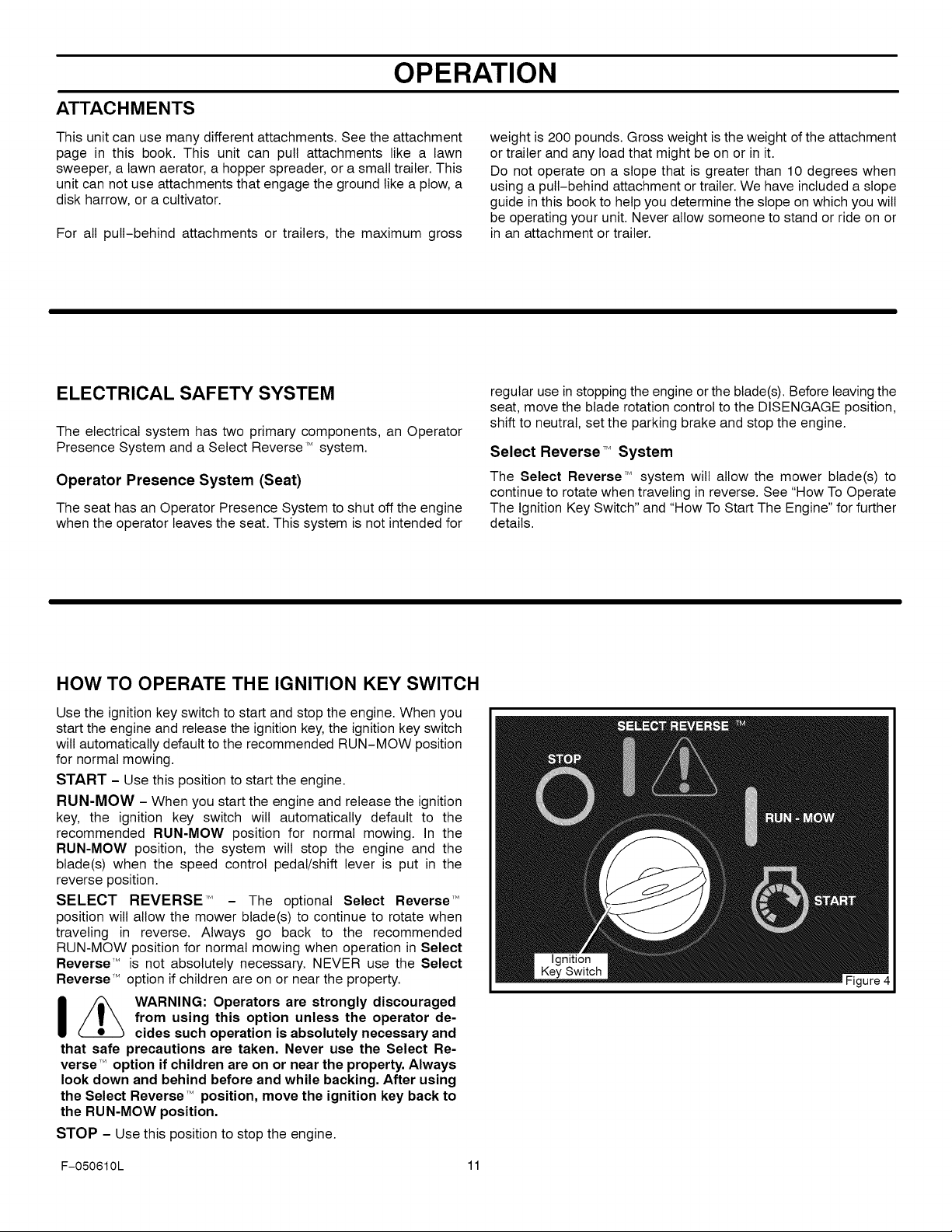
HOW TO OPERATE THE IGNITION KEY SWITCH
Use the ignition key switch to start and stop the engine. When you
start the engine and release the ignition key, the ignition key switch
wilt automatically default to the recommended RUN-MOW position
for normal mowing.
START - Use this position to start the engine.
RUN-MOW - When you start the engine and release the ignition
key, the ignition key switch will automatically default to the
recommended RUN-MOW position for normal mowing. In the
RUN-MOW position, the system will stop the engine and the
blade(s) when the speed control pedal/shift lever is put in the
reverse position.
SELECT REVERSE 'M - The optional Select Reverse '_
position wilt allow the mower blade(s) to continue to rotate when
traveling in reverse. Always go back to the recommended
RUN-MOW position for normal mowing when operation in Select
Reverse '" is not absolutely necessary. NEVER use the Select
Reverse'M option if children are on or near the property.
_ WARNING: Operators are strongly discouraged
that safe precautions are taken. Never use the Select Re-
verse ,Moption if children are on or near the property. Always
look down and behind before and while backing. After using
the Select Reverse M position, move the ignition key back to
the RUN-MOW position.
STOP - Use this position to stop the engine.
from using this option unless the operator de-
cides such operation is absolutely necessary and
F-050610L 11
OPERATION
HOW TO STOP THE UNIT
1. Completely push the clutch/brake pedal forward to stop the
unit. Keep your foot on the pedal.
2. Move the attachment clutch to the DISENGAGE position.
3. Move the speed control lever to the NEUTRAL position.
4. Set the parking brake.
HOW TO SET THE PARKING BRAKE
1. Completely push the clutch/brake pedal forward.
2. Lift the parking brake lever (Figure 5).
3. Remove your foot from the clutch/brake pedal and then release
the parking brake lever. Make sure the parking brake will hold
the unit.
4. To release the parking brake, completely push the clutch/
brake pedal forward. The parking brake will automatically re-
lease.
_ ARNING: Make sure the parking brake will hold the
5. Move the throttle control to the SLOW position.
6. To stop the engine, turn the ignition key to the STOP O posi-
Clutch/Brake
unit.
tion. Remove the key.
Pedal
WARNING: Before you leave the operator's position,
,_ move the shift lever to the neutral (N) position. Set the
parking brake. Move the attachment clutch to the
DISENGAGE position. Stop the engine and remove
the ignition key.
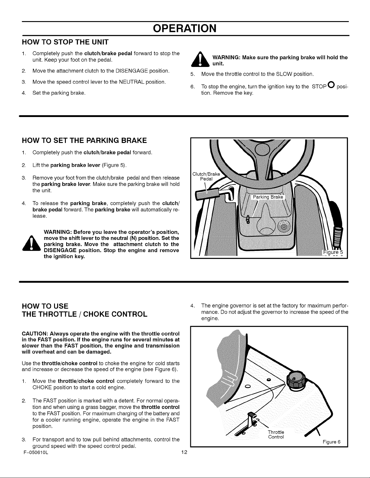
HOW TO USE
THE THROTTLE / CHOKE CONTROL
CAUTION: Always operate the engine with the throttle control
in the FAST position. If the engine runs for several minutes at
slower than the FAST position, the engine and transmission
will overheat and can be damaged.
Use the throttle/choke control to choke the engine for cold starts
and increase or decrease the speed of the engine (see Figure 6).
1. Move the throttle/choke control completely forward to the
CHOKE position to start a cold engine.
2.
The FAST position is marked with a detent. For normal opera-
tion and when using a grass bagger, move the throttle control
to the FAST position. For maximum charging of the battery and
for a cooler running engine, operate the engine in the FAST
position.
3. For transport and to tow pull behind attachments, control the
ground speed with the speed control pedal.
F-050610L
4.
The engine governor is set at the factory for maximum perfor-
mance. Do not adjust the governor to increase the speed of the
engine.
Throttle
Control
12
Figure 6
OPERATION
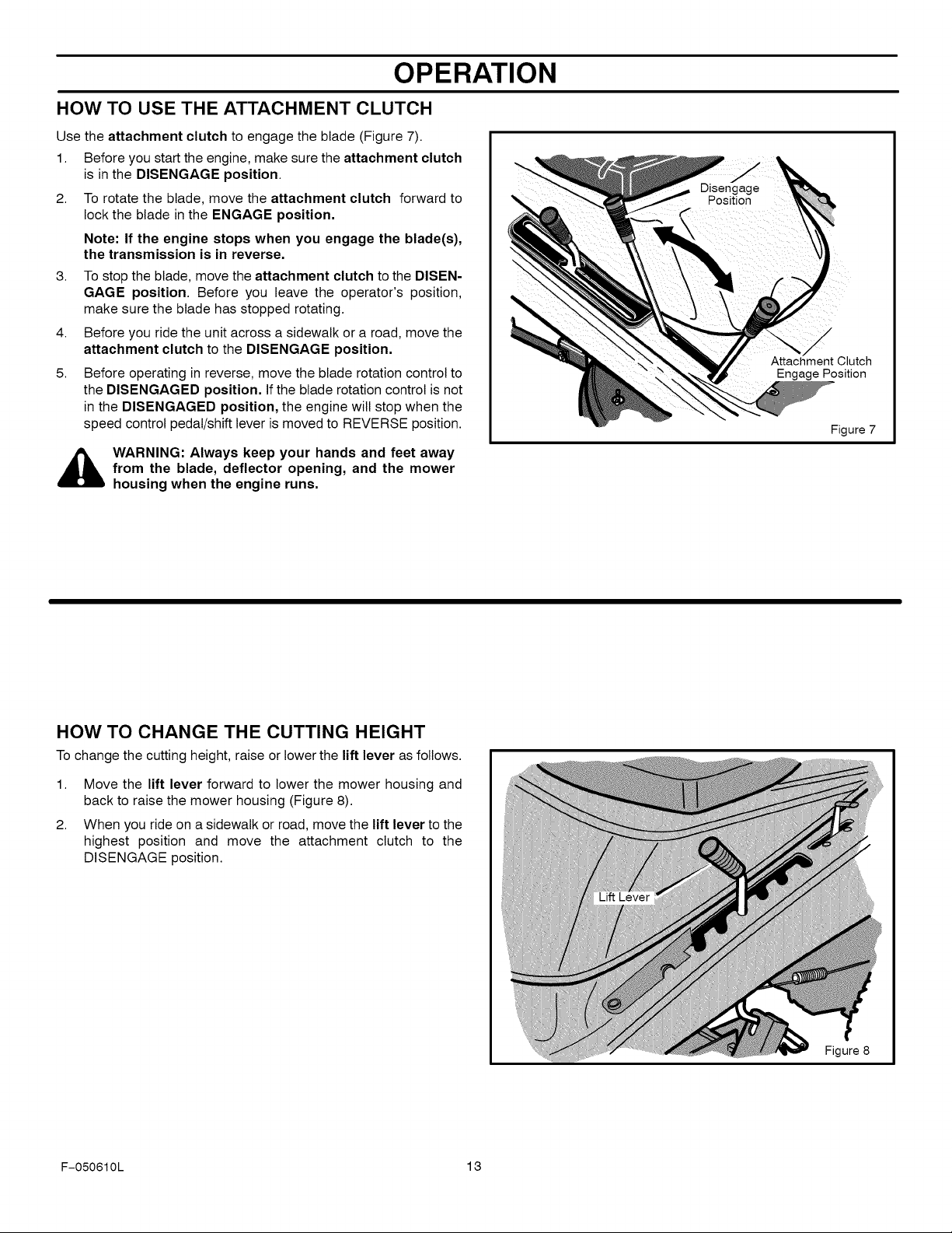
HOW TO USE THE ATTACHMENT CLUTCH
Use the attachment clutch to engage the blade (Figure 7).
1. Before you start the engine, make sure the attachment clutch
is in the DISENGAGE position.
2. To rotate the blade, move the attachment clutch forward to
lock the blade in the ENGAGE position.
Note: If the engine stops when you engage the blade(s),
the transmission is in reverse.
3. To stop the blade, move the attachment clutch to the DISEN-
GAGE position. Before you leave the operator's position,
make sure the blade has stopped rotating.
4. Before you ride the unit across a sidewalk or a road, move the
attachment clutch to the DISENGAGE position.
5. Before operating in reverse, move the blade rotation control to
the DISENGAGED position. If the blade rotation control is not
in the DISENGAGED position, the engine will stop when the
speed control pedal/shift lever is moved to REVERSE position.
Attachment Clutch
Engage Position
Figure 7
,_ WARNING: Always keep your hands and feet away
from the blade, deflector opening, and the mower
housing when the engine runs.
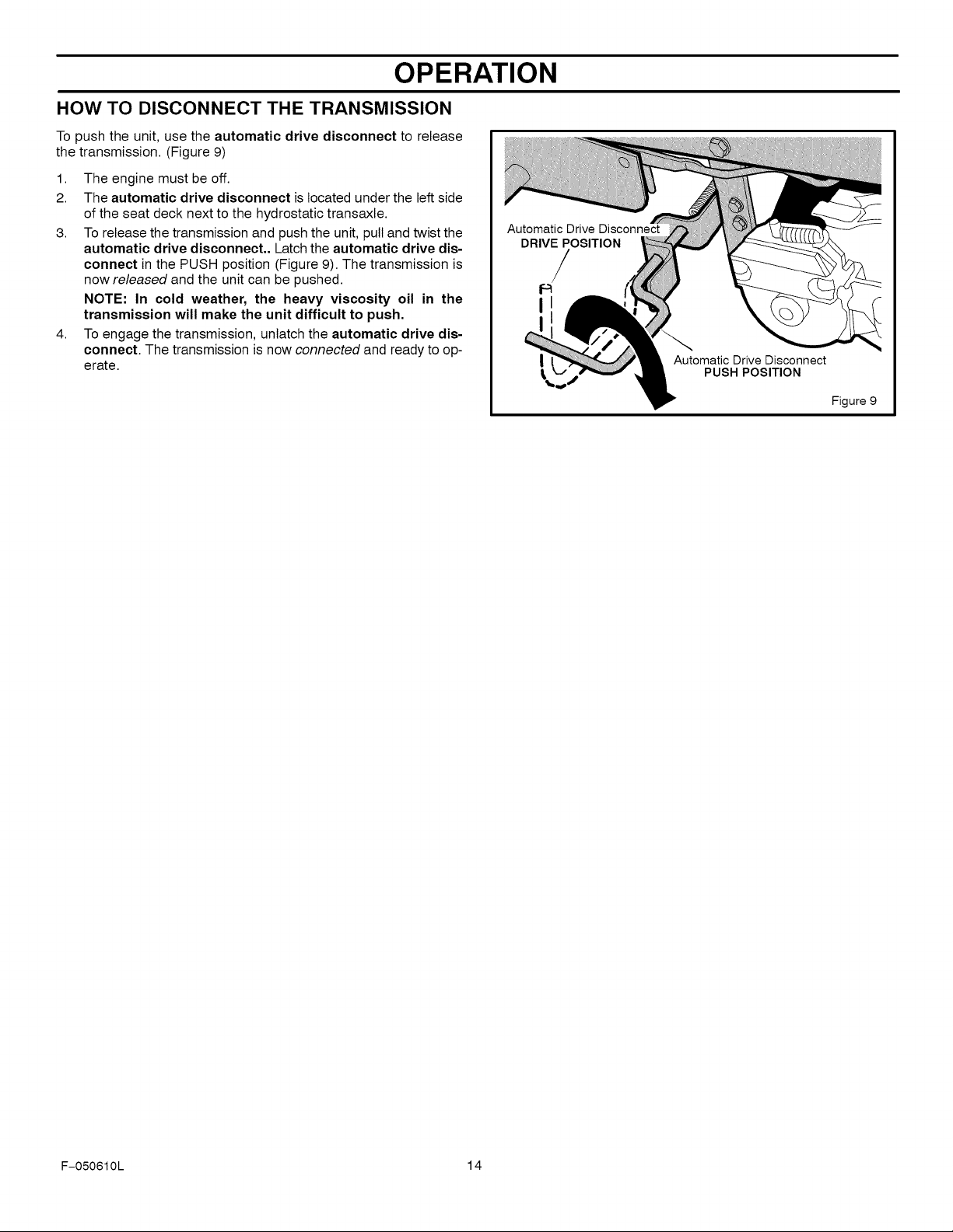
HOW TO CHANGE THE CUTTING HEIGHT
To change the cutting height, raise or lower the lift lever as follows.
1. Move the lift lever forward to lower the mower housing and
back to raise the mower housing (Figure 8).
2. When you ride on a sidewalk or road, move the lift lever to the
highest position and move the attachment clutch to the
DISENGAGE position.
F-050610L 13
Figure 8
OPERATION
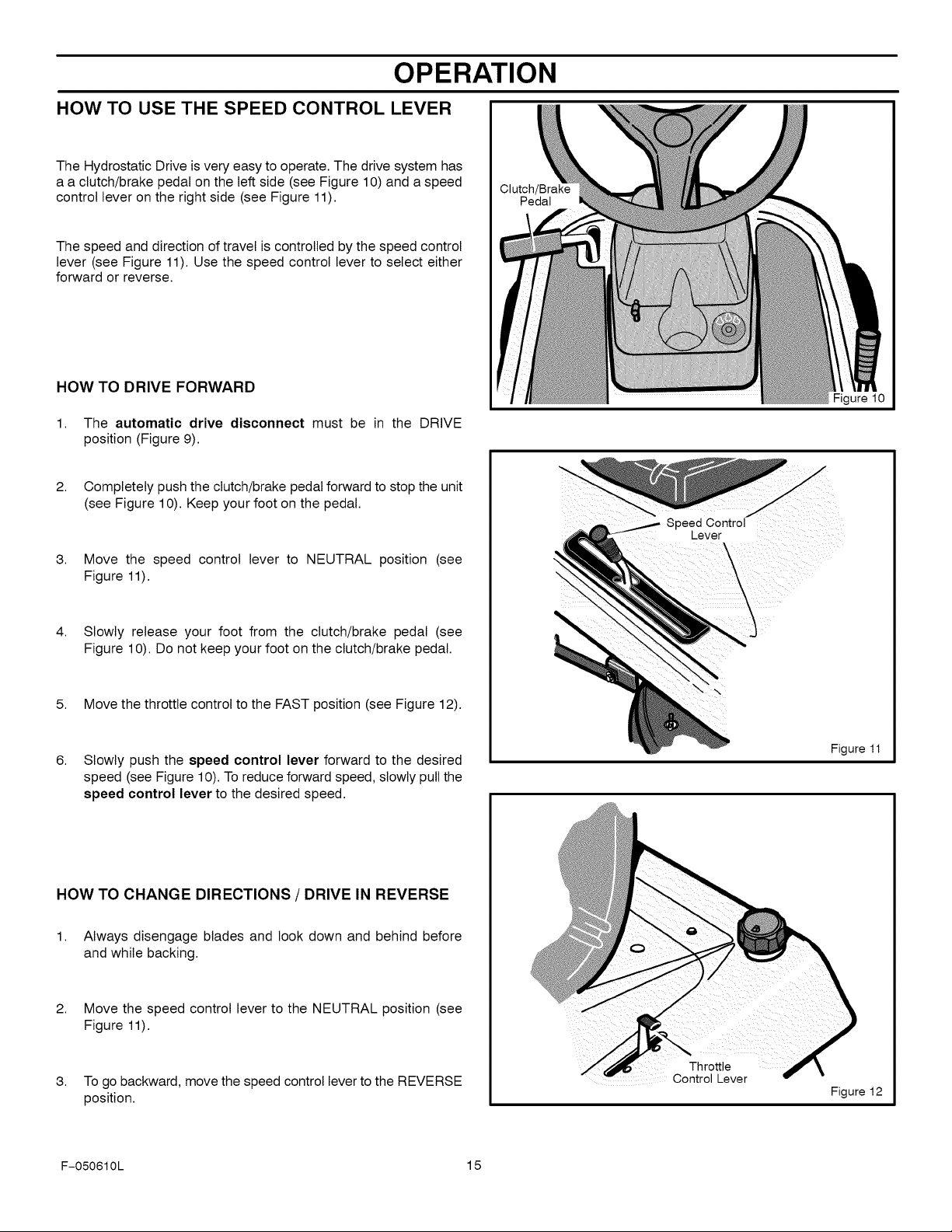
HOW TO DISCONNECT THE TRANSMISSION
To push the unit, use the automatic drive disconnect to release
the transmission. (Figure 9)
1. The engine must be off.
2. The automatic drive disconnect is located under the left side
of the seat deck next to the hydrostatic transaxle.
3. To release the transmission and push the unit, pull and twist the
automatic drive disconnect.. Latch the automatic drive dis-
connect in the PUSH position (Figure 9). The transmission is
now released and the unit can be pushed.
NOTE: In cold weather, the heavy viscosity oil in the
transmission will make the unit difficult to push.
4. To engage the transmission, unlatch the automatic drive dis-
connect. The transmission is now connected and ready to op-
erate.
Automatic Drive Disconnect
DRIVEPOSITION
/
Automatic Drive Disconnect
PUSH POSITION
Figure 9
F-050610L 14
OPERATION
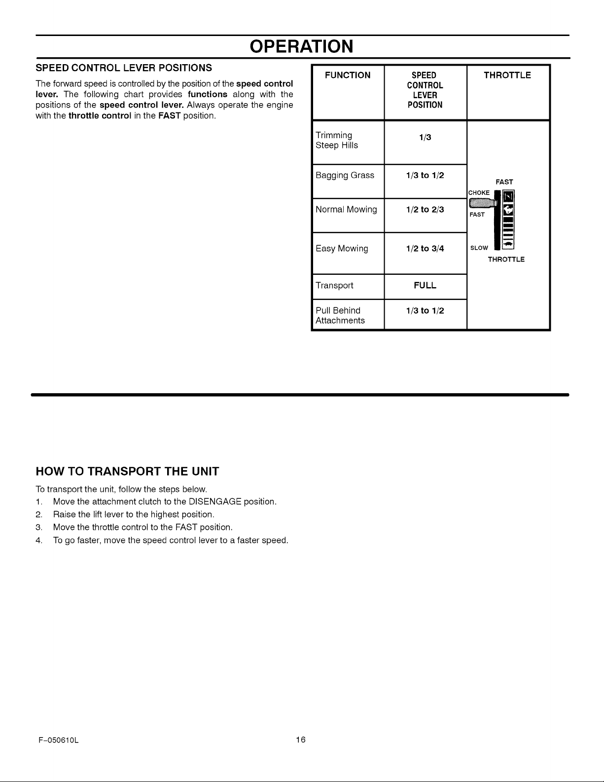
HOW TO USE THE SPEED CONTROL LEVER
The Hydrostatic Drive is very easy to operate. The drive system has
a a clutch/brake pedal on the left side (see Figure 10) and a speed
control lever on the right side (see Figure 11).
The speed and direction of travel is controlled by the speed control
lever (see Figure 11). Use the speed control lever to select either
forward or reverse.
Clutch/Brake
Pedal
HOW TO DRIVE FORWARD
1. The automatic drive disconnect must be in the DRIVE
position (Figure 9).
2.
Completely push the clutch/brake pedal forward to stop the unit
(see Figure 10). Keep your foot on the pedal.
3.
Move the speed control lever to NEUTRAL position (see
Figure 11).
4.
Slowly release your foot from the clutch/brake pedal (see
Figure 10). Do not keep your foot on the clutch/brake pedal.
5. Move the throttle control to the FAST position (see Figure 12).
6.
Slowly push the speed control lever forward to the desired
speed (see Figure 10). To reduce forward speed, slowly pull the
speed control lever to the desired speed.
Speea Control
_ever
Figure 10
\
\
Figure 11
HOW TO CHANGE DIRECTIONS / DRIVE IN REVERSE
1. Always disengage blades and look down and behind before
and while backing.
2. Move the speed control lever to the NEUTRAL position (see
Figure 11).
3. To go backward, move the speed control lever to the REVERSE
position.
F-050610L 15
Throttle
Control Lever
Figure 12
OPERATION
SPEED CONTROL LEVER POSITIONS
The forward speed is controlled by the position of the speed control
lever. The following chart provides functions along with the
positions of the speed control lever. Always operate the engine
with the throttle control in the FAST position.
FUNCTION
Trimming
Steep Hills
Bagging Grass 1/3 to 1/2
Normal Mowing 1/2 to 2/3
Easy Mowing 1/2 to 3/4
Transport
Pull Behind
Attachments
SPEED
CONTROL
LEVER
POSITION
1/3
FULL
1/3 to 1/2
THROTTLE
FAST
THROTTLE
HOW TO TRANSPORT THE UNIT
Totransport the unit, follow the steps below.
1. Move the attachment clutch to the DISENGAGE position.
2. Raise the lift lever to the highest position.
3. Move the throttle control to the FAST position.
4. To go faster, move the speed control lever to a faster speed.
F-050610L 16
OPERATION
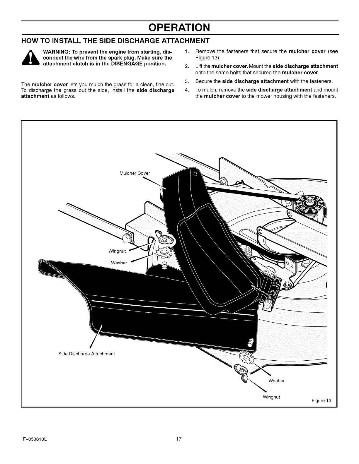
HOW TO INSTALL THE SIDE DISCHARGE ATTACHMENT
1.
Remove the fasteners that secure the mulcher cover (see
,_ WARNING: To prevent the engine from starting, dis-
connect the wire from the spark plug. Make sure the
attachment clutch is in the DISENGAGE position.
The mulcher cover lets you mulch the grass for a clean, fine cut.
To discharge the grass out the side, install the side discharge
attachment as follows.
Mulcher Cover
Figure 13).
2.
Lift the mulcher cover. Mount the side discharge attachment
onto the same bolts that secured the mulcher cover.
3.
Secure the side discharge attachment with the fasteners.
4.
To mulch, remove the side discharge attachment and mount
the mulcher cover to the mower housing with the fasteners.
Side Discharge Attachment
Wingnut
Washer
Washer
Wingnut
Figure 13
F-050610L 17

BEFORE STARTING THE ENGINE
OPERATION
CHECK THE OIL
NOTE: The engine was shipped from the factory filled with oil
rated 30. Check the level of the oil. Add oil as needed.
1. Make sure the unit is level.
NOTE: Do not check the level of the oil while the engine
runs.
2. Clean the area around the dipstick. Remove the dipstick. Wipe
the oil from the dipstick.
3. Insert the dipstick into the oil fill tube. Turn the dipstick clock-
wise until itis tight. Remove the dipstick. Check the oil level on
the dipstick. The oil level must reach the FULL mark on the
dipstick.
4. If necessary, add oil until the oil reaches the FULL mark on the
dipstick. The quantity of oil needed from ADD to FULL is shown
on the dipstick. Do not add too much oil.
ADD GASOLINE
WARNING: Always use a safety gasoline container.
Do not smoke when adding gasoline to the fuel tank.
Do not add gasoline when you are inside an enclo-
sure. Before you add gasoline, stop the engine and
let the engine cool for several minutes.
Use clean, fresh, regular unleaded gasoline with a minimum of 85
octane. Fresh fuel prevents gum from forming in the fuel system or
on essential carburetor parts. Purchase fuel in quantity that can be
used with 30 days.
• Do not use gasoline which FuelTank
CAUTION: Alcohol blended fuels (called gasohol or using
ethanol or methanol) can attract moisture which leads to
separation and formation of acids during storage. Acidic gas
can damage the fuel system of an engine while in storage.
To prevent engine problems with the fuel system, empty the fuel
system before storage of 30 days or longer as follows.
Drain the fuel tank.1.
2.
Start the engine. Let the engine run until the fuel lines and the
carburetor are empty.
3.
After storage, make sure you use fresh fuel. See the storage
instructions for additional information.
4.
Never use engine cleaner or carburetor cleaner inthe fuel tank
or permanent damage can occur.
CARBURETOR
The factory settings for the carburetor are for most conditions. If the
engine is operated under the following conditions, you can adjust
the carburetor mixture. See "How To Adjust The Carburetor" in the
Service And Adjustment section.
1. The engine has a loss of power or does not run smooth.
2. A change from summer to winter operation.
3. A 40 degree change inthe operation temperature. The carbure-
tor was adjusted at 80 degrees at the factory.
4. The engine is operated above 4,000 feet.
• Do not mix oil with gasoline.
• For engine protection, use a
contains Methanol.
fuel stabilizer available at a
Sears Store or Service Center.
• This engine is certified to operate on gasoline. Exhaust Emission
Control System: EM (Engine Modifications).
HOW TO START THE ENGINE
WARNING: The electrical system has two primary
components, an operator presence system and a Se-
lect Reverse M system. The operator presence sys-
tem determines if the operator is sitting on the seat.
This system will stop the engine when the operator
leaves the seat.attachment clutch The Select Rever-
se M system gives the operator the ability to tempo-
rarily mow in reverse if he decides such operation is
absolutely necessary and safe operating precautions
are taken. For your protection, always make sure the-
se systems operate correctly.
NOTE: The engine will not start unless you depress the
clutch/brake pedal or engage the parking brake and move the
attachment clutch to the DISENGAGE position.
1.
Make sure the spark plug wire is connected to the spark plug. 6.
2.
Move the speed control lever to the neutral (N) position.
3.
Make sure the attachment clutch is in the DISENGAGE posi- 7.
tion. If the blade rotation control is not in the DISENGAGE posi-
tion, the engine wilt not start.
F-050610L 18
4.
Move the throttle control completely forward to the CHOKE I\1
or FAST position. Some models have a separate choke knob.
Pull the choke knob to the full CHOKE position.
5.
Turn the ignition key to the START _ position. Release the
key when the engine starts. The ignition key switch will auto-
matically default to the recommended RUN-MOW position for
normal mowing. See "How To Operate The Ignition Key Switch"
in the Operation Section.
NOTE: If the engine does not start after four or five tries,
move the throttle control to the FAST position. Again try to
start the engine. If the engine will not start, see the
TROUBLESHOOTING CHART.
Slowly move the throttle control to the SLOW position. If model
has a separate choke knob, push in the choke knob.
Let a cold engine run for several minutes. Begin work when the
engine is warm. To start a hot engine, move the throttle control
to a position between FAST and SLOW.
OPERATION
HOWTO OPERATEWITH THE MOWER HOUSING
WARNING: The mulch cover is a safety device. Do not
remove the mulch cover. The side discharge attach-
,_ ment forces the discharged material toward the
ground. Always keep the side discharge attachment
in the down position. If the side discharge attachment
is damaged, replace the with an original equipment
part from a Sears Service Center.
IMPORTANT: When you operate with the mower housing,
always operate with the throttle control in the FAST position.
1. Push the clutch/brake pedal completely forward.
2. Start the engine.
3. Put the speed control lever in the NEUTRAL position.
4. Slowly release the clutch/brake pedal.
5. Move the lift lever to a height of cut position. In high or thick
grass, cut the grass in the highest position first and then lower
the mower housing to a lower position.
CAUTION: Do not operate with the mower housing in the
LEVEL ADJUSTMENT position. If you operate in the
LEVEL ADJUSTMENT position, the mower housing and
blades can be damaged.
6.
Move the throttle control to the SLOW position.
7.
Move the attachment clutch to the ENGAGE position.
8.
Move the speed control lever forward.
NOTE: When you mow in heavy grass or mow with a
bagger, operate at a slow forward speed.
9.
Move the throttle control to the FAST position. If you need to go
faster or slower, move the speed control lever forward or back-
ward.
10.
Make sure the level of cut is still correct. After you mow a short
distance, look at the area that was cut. If the mower housing
does not cut level, see the instructions on "How To Level The
Mower Housing" in the Service And Adjustment section.
,_ WARNING: For better control of the unit, always
select a safe speed.
HOW TO OPERATE THE UNIT ON HILLS
,_ WARNING: Do not ride up or down slopes that are too
1. Before you ride up or down a hill, move the speed control lever
2. Do not stop or change speed settings on a hill. If you must stop,
steep to back straight up. Never ride the unit across
a slope. See the "Slope Guide" in the back of this
book for information on how to check slopes.
to a slow speed.
quickly push the clutch/brake pedal forward and set the parking
brake.
3. To start again, make sure the speed controllever is in a slow
speed. Move the throttle control to the SLOW position. Slowly
release the pedal.
4. If you must stop or start on a hill, always have enough space
for the unit to roll when you release the brake and engage the
clutch.
5.
Be very careful when you change directions on a hill. When on
a slope or in a turn on a hill, move the throttle control to the
SLOW position to help prevent an accident.
F-050610L 19
OPERATION
OPERATING TIPS
1.
Check the attachment clutch for correct adjustment. For the
blade(s) to disengage correctly, the adjustment must be cor-
rect.
2.
Before you use the unit, check the oil in the engine and add oil
if necessary.
3.
If the engine will not start, first make sure the wire is attached
to the spark plug.
4.
Make sure all the belts are inside all the belt guides. See the in-
structions on how to remove and install the motion drive and
mower drive belts.
MOWING AND BAGGING TIPS
1.
For a lawn to look better, check the cutting level of the mower
housing. See "How To Level The Mower Housing" in the Ser-
vice And Adjustment section.
2.
For the mower housing to cut level, make sure the tires have
the correct amount of air pressure (PSI) and use slow ground
speeds when turning.
3.
Every time you use the unit, check the blade. If the blade is bent
or damaged, immediately replace the blade. Also, make sure
the nut for the blade is tight.
4.
Keep the blade(s) sharpened. A worn blade(s) will cause the
ends of the grass to turn brown.
5.
Do not cut or bag grass that iswet. Wet grass will not discharge
correctly. Let the grass dry before cutting.
6.
Use the left side of the mower housing to trim near an object.
7.
Discharge the cut grass onto the mowed area. The result is a
more even discharge of cut grass.
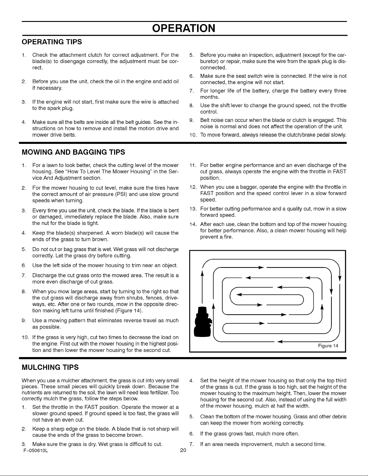
8.
When you mow large areas, start by turning to the right so that
the cut grass wilt discharge away from shrubs, fences, drive-
ways, etc. After one or two rounds, mow in the opposite direc-
tion making left turns until finished (Figure 14).
9.
Use a mowing pattern that eliminates reverse travel as much
as possible.
10.
If the grass is very high, cut two times to decrease the load on
the engine. First cut with the mower housing in the highest posi-
tion and then lower the mower housing for the second cut.
5. Before you make an inspection, adjustment (except for the car-
buretor) or repair, make sure the wire from the spark plug is dis-
connected.
6. Make sure the seat switch wire is connected. If the wire is not
connected, the engine will not start.
7. For longer life of the battery, charge the battery every three
months.
8. Use the shift lever to change the ground speed, not the throttle
control.
9. Belt noise can occur when the blade or clutch is engaged. This
noise is normal and does not affect the operation of the unit.
10. To move forward, always release the clutch/brake pedal slowly.
11. For better engine performance and an even discharge of the
cut grass, always operate the engine with the throttle in FAST
position.
12. When you use a bagger, operate the engine with the throttle in
FAST position and the speed control lever in a slow forward
speed.
13. For better cutting performance and a quality cut, mow in a slow
forward speed.
14. After each use, clean the bottom and top of the mower housing
for better performance. Also, a clean mower housing will help
prevent a fire.
f
v
(
J
Figure14
MULCHING TIPS
When you use a mulcher attachment, the grass is cut into very small 4.
pieces. These small pieces will quickly break down. Because the
nutrients are returned to the soil, the lawn will need less fertilizer. Too
correctly mulch the grass, follow the steps below.
1. Set the throttle in the FAST position. Operate the mower at a
slower ground speed. If ground speed is too fast, the grass will 5.
not have an even cut.
2. Keep a sharp edge on the blade. A blade that is not sharp will
cause the ends of the grass to become brown. 6.
3. Make sure the grass is dry. Wet grass is difficult to cut. 7.
F-050610L 20
Set the height of the mower housing so that only the top third
of the grass is cut. If the grass is too high, set the height of the
mower housing to the maximum height. Then, lower the mower
housing for the second cut. Also, instead of using the full width
of the mower housing, mulch at half the width.
Clean the bottom of the mower housing. Grass and other debris
can keep the mower from working correctly.
If the grass grows fast, mulch more often.
If an area needs improvement, mulch a second time.
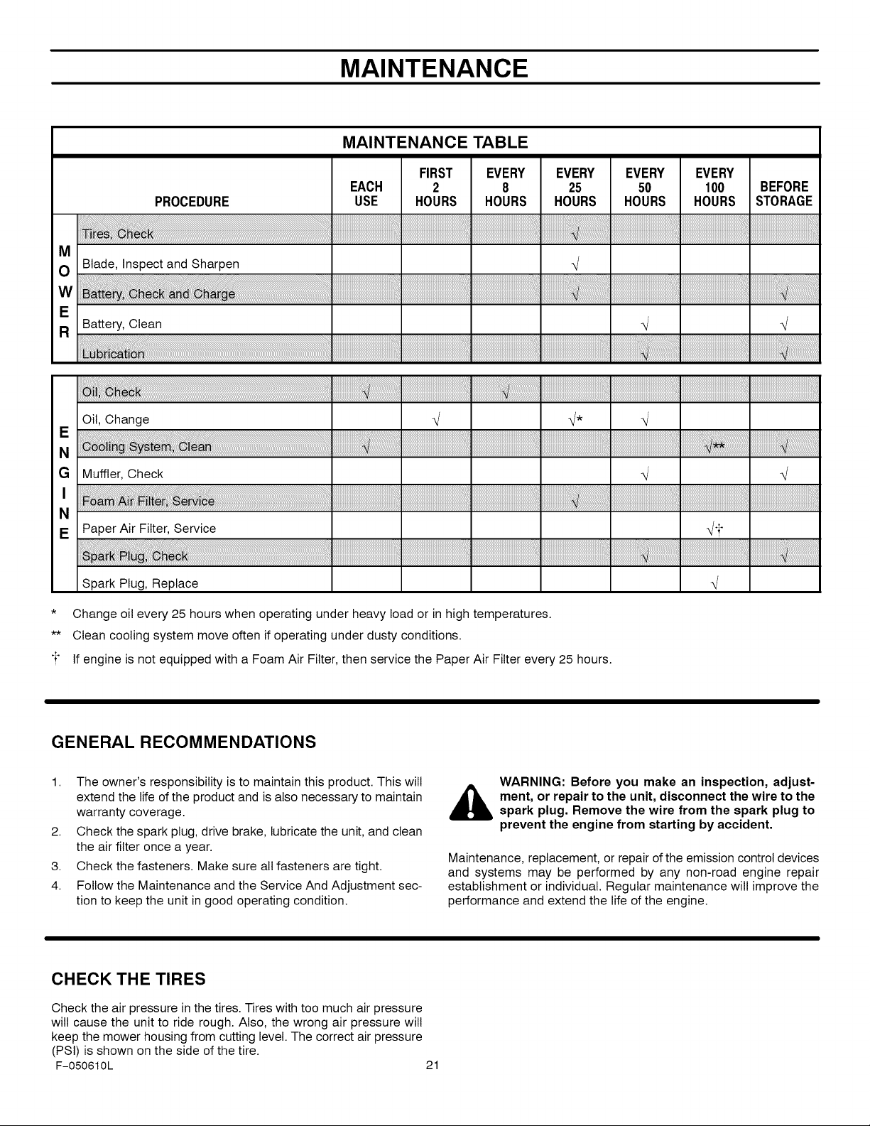
MAINTENANCE
MAINTENANCE TABLE
PROCEDURE
M
O Blade, Inspect and Sharpen
FIRST
EACH 2
USE HOURS
EVERY EVERY EVERY EVERY
8 25 50 100 BEFORE
HOURS HOURS HOURS HOURS STORAGE
4
w ................................................................
E
R Battery, Clean
!ati
Oil, Change
E
N
Spark Plug, Replace
4 _
4
* Change oil every 25 hours when operating under heavy load or in high temperatures.
** Clean cooling system move often if operating under dusty conditions.
"i" If engine is not equipped with a Foam Air Filter, then service the Paper Air Filter every 25 hours.
GENERAL RECOMMENDATIONS
1. The owner's responsibility is to maintain this product. This wilt
extend the life of the product and is also necessary to maintain
warranty coverage.
2. Check the spark plug, drive brake, lubricate the unit, and clean
the air filter once a year.
3. Check the fasteners. Make sure all fasteners are tight.
4. Follow the Maintenance and the Service And Adjustment sec-
tion to keep the unit in good operating condition.
,_ ment, or repair to the unit, disconnect the wire to the
Maintenance, replacement, or repair of the emission control devices
and systems may be performed by any non-road engine repair
establishment or individual. Regular maintenance wilt improve the
performance and extend the life of the engine.
WARNING: Before you make an inspection, adjust-
spark plug. Remove the wire from the spark plug to
prevent the engine from starting by accident.
CHECK THE TIRES
Check the air pressure in the tires. Tires with too much air pressure
will cause the unit to ride rough. Also, the wrong air pressure will
keep the mower housing from cutting level. The correct air pressure
(PSI) is shown on the side of the tire.
F-050610L 21
MAINTENANCE
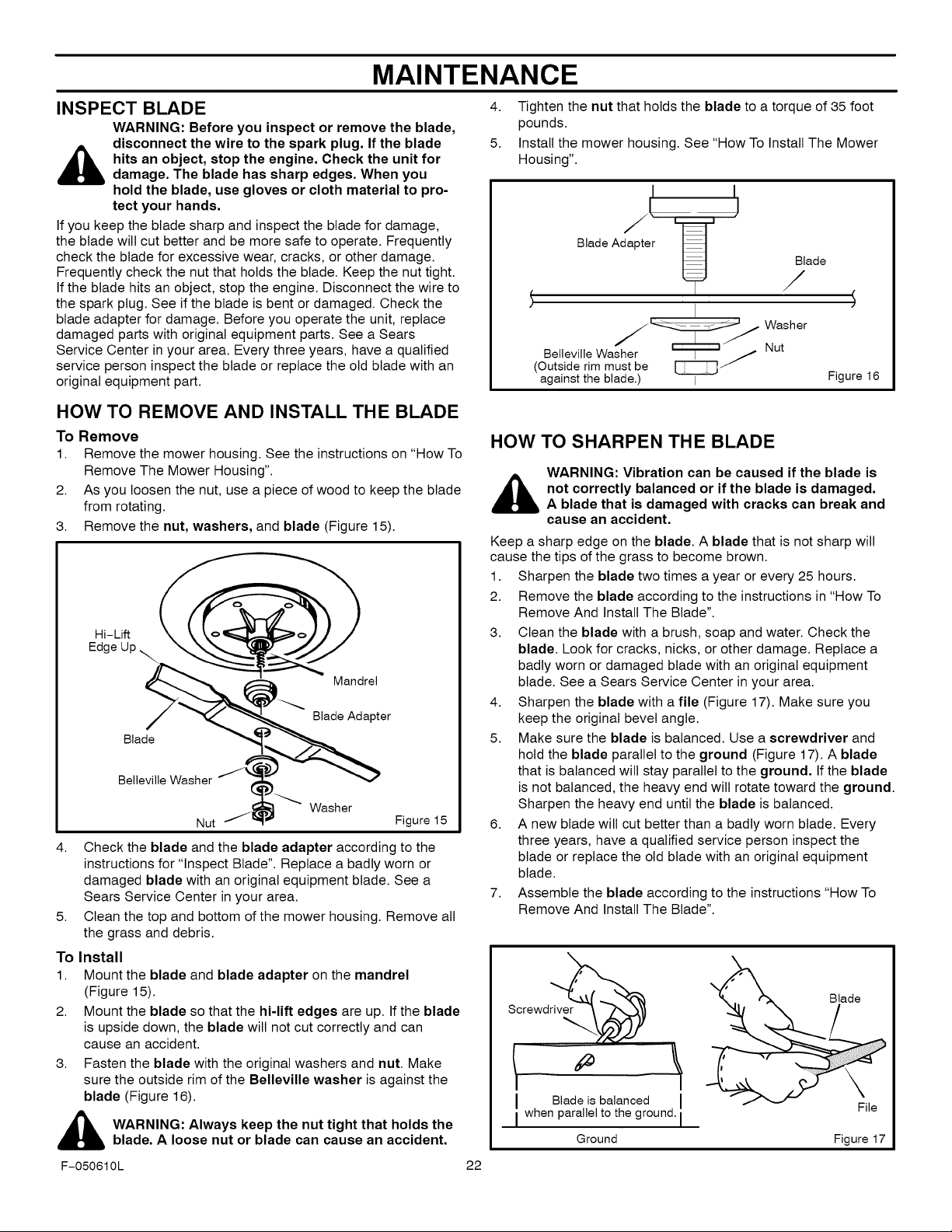
INSPECT BLADE
WARNING: Before you inspect or remove the blade,
disconnect the wire to the spark plug. If the blade
,_ hits an object, stop the engine. Check the unit for
If you keep the blade sharp and inspect the blade for damage,
the blade will cut better and be more safe to operate. Frequently
check the blade for excessive wear, cracks, or other damage.
Frequently check the nut that holds the blade. Keep the nut tight.
If the blade hits an object, stop the engine. Disconnect the wire to
the spark plug. See if the blade is bent or damaged. Check the
blade adapter for damage. Before you operate the unit, replace
damaged parts with original equipment parts. See a Sears
Service Center in your area. Every three years, have a qualified
service person inspect the blade or replace the old blade with an
original equipment part.
damage. The blade has sharp edges. When you
hold the blade, use gloves or cloth material to pro-
tect your hands.
HOW TO REMOVE AND INSTALL THE BLADE
To Remove
1. Remove the mower housing. See the instructions on "How To
Remove The Mower Housing".
2. As you loosen the nut, use a piece of wood to keep the blade
from rotating.
3. Remove the nut, washers, and blade (Figure 15).
Hi-Lift
Edge
Mandrel
Blade Adapter
Blade
Belleville Washer
Nut Figure 15
4. Check the blade and the blade adapter according to the
instructions for "Inspect Blade". Replace a badly worn or
damaged blade with an original equipment blade. See a
Sears Service Center in your area.
5. Clean the top and bottom of the mower housing. Remove all
the grass and debris.
To Install
1. Mount the blade and blade adapter on the mandrel
(Figure 15).
2. Mount the blade so that the hi-lift edges are up. If the blade
is upside down, the blade wilt not cut correctly and can
cause an accident.
3. Fasten the blade with the original washers and nut. Make
sure the outside rim of the Belleville washer is against the
blade (Figure 16).
,_ WARNING: Always keep the nut tight that holds the
F-050610L 22
blade. A loose nut or blade can cause an accident.
Washer
4. Tighten the nut that holds the blade to a torque of 35 foot
pounds.
5. Install the mower housing. See "How To Install The Mower
Housing".
I
Blade Adapter
BellevilleWasher _ j Nut
(Outside rim must be
against the blade.) I
j' ...... Washer
r-_m/
HOW TO SHARPEN THE BLADE
WARNING: Vibration can be caused if the blade is
,_not correctly balanced or if the blade is damaged.
Keep a sharp edge on the blade. A blade that is not sharp wilt
cause the tips of the grass to become brown.
1. Sharpen the blade two times a year or every 25 hours.
2. Remove the blade according to the instructions in "How To
3. Clean the blade with a brush, soap and water. Check the
4. Sharpen the blade with a file (Figure 17). Make sure you
5. Make sure the blade is balanced. Use a screwdriver and
6. A new blade will cut better than a badly worn blade. Every
7. Assemble the blade according to the instructions "How To
A blade that is damaged with cracks can break and
cause an accident.
Remove And Install The Blade".
blade. Look for cracks, nicks, or other damage. Replace a
badly worn or damaged blade with an original equipment
blade. See a Sears Service Center in your area.
keep the original bevel angle.
hold the blade parallel to the ground (Figure 17). A blade
that is balanced will stay parallel to the ground. If the blade
is not balanced, the heavy end will rotate toward the ground.
Sharpen the heavy end until the blade is balanced.
three years, have a qualified service person inspect the
blade or replace the old blade with an original equipment
blade.
Remove And Install The Blade".
Screwd_
[ Blade isbalanced
[ when parallelto the ground.
Ground
Blade
Figure 16
MAINTENANCE FREE BATTERY
MAINTENANCE
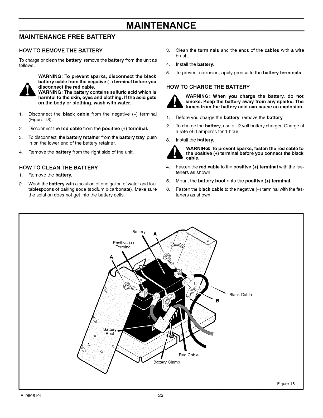
HOW TO REMOVE THE BATTERY
To charge or clean the battery, remove the battery from the unit as
follows.
WARNING: To prevent sparks, disconnect the black
battery cable from the negative (-) terminal before you
,_ disconnect the red cable.
1. Disconnect the black cable from the negative (-) terminal
2. Disconnect the red cable from the positive (+) terminal.
3. To disconnect the battery retainer from the battery tray, push
4. Remove the battery from the right side of the unit.
WARNING: The battery contains sulfuric acid which is
harmful to the skin, eyes and clothing. If the acid gets
on the body or clothing, wash with water.
(Figure 18).
in on the lower end of the battery retainer.
HOW TO CLEAN THE BATTERY
1. Removethe battery.
2. Wash the battery with a solution of one gallon of water and four
tablespoons of baking soda (sodium bicarbonate). Make sure
the solution does not get into the battery cells.
Clean the terminals and the ends of the cables with a wire
3.
brush.
4.
Install the battery.
5.
To prevent corrosion, apply grease to the battery terminals.
HOW TO CHARGE THE BATTERY
,_ WARNING: When you charge the battery, do not
1. Before you charge the battery, remove the battery.
2. To charge the battery, use a 12 volt battery charger. Charge at
3. Install the battery.
,_ WARNING: To prevent sparks, fasten the red cable tothe positive (+) terminal before you connect the black
4. Fasten the red cable to the positive (+) terminal with the fas-
5. Mount the battery boot onto the positive (+) terminal.
6. Fasten the black cable to the negative (-) terminal with the fas-
smoke. Keep the battery away from any sparks. The
fumes from the battery acid can cause an explosion.
a rate of 6 amperes for 1 hour.
cable.
teners as shown.
teners as shown.
Positive (+)
Terminal
A
Battery A
Black Cable
B
Red Cable
Battery Clamp
Figure 18
F-050610L 23
MAINTENANCE
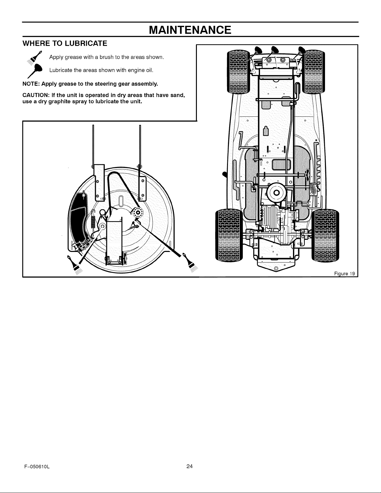
WHERE TO LUBRICATE
Apply grease with a brush to the areas shown.
Lubricate the areas shown with engine oil.
NOTE: Apply grease to the steering gear assembly.
CAUTION: If the unit is operated in dry areas that have sand,
use a dry graphite spray to lubricate the unit.
F-050610L 24
MAINTENANCE
ENGINE
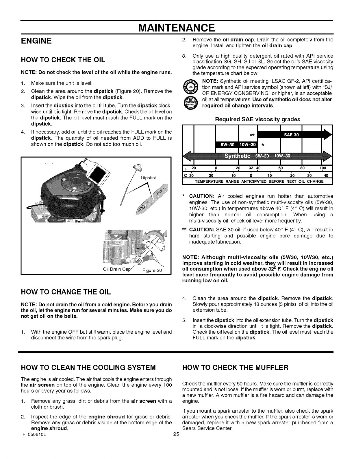
HOW TO CHECK THE OIL
NOTE: Do not check the level of the oil while the engine runs.
1. Make sure the unit islevel.
2. Clean the area around the dipstick (Figure 20). Remove the
dipstick. Wipe the oil from the dipstick.
3. Insert the dipstick into the oil fill tube. Turn the dipstick clock-
wise until it is tight. Remove the dipstick. Check the oil level on
the dipstick. The oil level must reach the FULL mark on the
dipstick.
4. If necessary, add oil until the oil reaches the FULL mark on the
dipstick. The quantity of oil needed from ADD to FULL is
shown on the dipstick. Do not add too much oil.
Dipstick
2. Remove the oil drain cap. Drain the oil completely from the
engine. Install and tighten the oil drain cap.
3. Only use a high quality detergent oil rated with API service
classification SG, SH, SJ or SL. Select the oil's SAE viscosity
grade according to the expected operating temperature using
the temperature chart below:
tion mark and API service symbol (shown at left) with "SJ/
NOTE: Synthetic oil meeting ILSAC GF-2, API certifica-
CF ENERGY CONSERVING" or higher, is an acceptable
oil at all temperatures. Use of synthetic oil does not alter
required oil change intervals.
Required SAE viscosity grades
_' "_I'_
I I
F 20 0 20 32 10 60 80 100
i
C 30 20 10 0 10 20 30 40
TEMPERATURE RANGE ANTICIPATED BEFORE NEXT OIL CHANGE
* CAUTION: Air cooled engines run hotter than automotive
engines. The use of non-synthetic multi-viscosity oils (5W-30,
10W-30, etc.) in temperatures above 40 ° F (4° C) wilt result in
higher than normal oil consumption. When using a
multi-viscosity oil, check oil level more frequently.
** CAUTION: SAE 30 oil, if used below 40 ° F (4° C), will result in
hard starting and possible engine bore damage due to
inadequate lubrication.
Oil Drain Cap / Figure 20
HOW TO CHANGE THE OIL
NOTE: Do not drain the oil from a cold engine. Before you drain
the oil, let the engine run for several minutes. Make sure you do
not get oil on the belts.
1. With the engine OFF but still warm, place the engine level and
disconnect the wire from the spark plug.
HOW TO CLEAN THE COOLING SYSTEM
The engine is air cooled. The air that cools the engine enters through
the air screen on top of the engine. Clean the engine every 100
hours or every year as follows.
1. Remove any grass, dirt or debris from the air screen with a
cloth or brush.
2. Inspect the edge of the engine shroud for grass or debris.
Remove any grass or debris visible at the bottom edge of the
engine shroud.
F-050610L
NOTE: Although multi-viscosity oils (5W30, 10W30, etc.)
improve starting in cold weather, they will result in increased
oil consumption when used above 320 F. Check the engine oil
level more frequently to avoid possible engine damage from
running low on oil.
4.
Clean the area around the dipstick. Remove the dipstick.
Slowly pour approximately 48 ounces (3 pints) of oil into the oil
extension tube.
5.
Insert the dipstick into the oil extension tube. Turn the dipstick
in a clockwise direction until it is tight. Remove the dipstick,
Check the oil level on the dipstick. The oil level must reach the
FULL mark on the dipstick.
HOW TO CHECK THE MUFFLER
Check the muffler every 50 hours. Make sure the muffler is correctly
mounted and is not loose. If the muffler is worn or burnt, replace with
a new muffler. A worn muffler is a fire hazard and can damage the
engine.
If you mount a spark arrester to the muffler, also check the spark
arrester when you check the muffler. If the spark arrester is worn or
damaged, replace it with a new spark arrester purchased from a
Sears Service Center.
25
MAINTENANCE
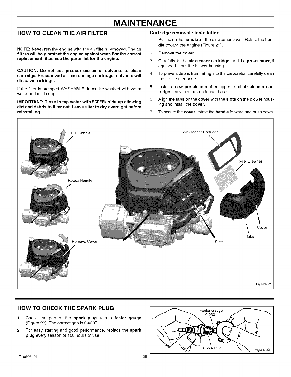
HOW TO CLEAN THE AIR FILTER
NOTE: Never run the engine with the air filters removed. The air
filters will help protect the engine against wear. For the correct
replacement filter, see the parts list for the engine.
CAUTION: Do not use pressurized air or solvents to clean
cartridge. Pressurized air can damage cartridge; solvents will
dissolve cartridge.
If the filter is stamped WASHABLE, it can be washed with warm
water and mild soap.
IMPORTANT: Rinse in tap water with SCREENside up allowing
dirt and debris to filter out. Leave filter to dry overnight before
reinstalling.
Pull Handle
Cartridge removal / installation
1. Pull up on the handle for the air cleaner cover. Rotate the han-
dle toward the engine (Figure 21).
2. Remove the cover.
3.
Carefully lift the air cleaner cartridge, and the pre-cleaner, if
equipped, from the blower housing.
4.
To prevent debris from falling into the carburetor, carefully clean
the air cleaner base.
5. Install a new pre-cleaner, if equipped, and air cleaner car-
tridge firmly into the air cleaner base.
6. Align the tabs on the cover with the slots on the blower hous-
ing and install the cover.
7.
To secure the cover, rotate the handle forward and push down.
Air
ge
\
Pre-Cleaner
Rotate Handle
Remove Cover
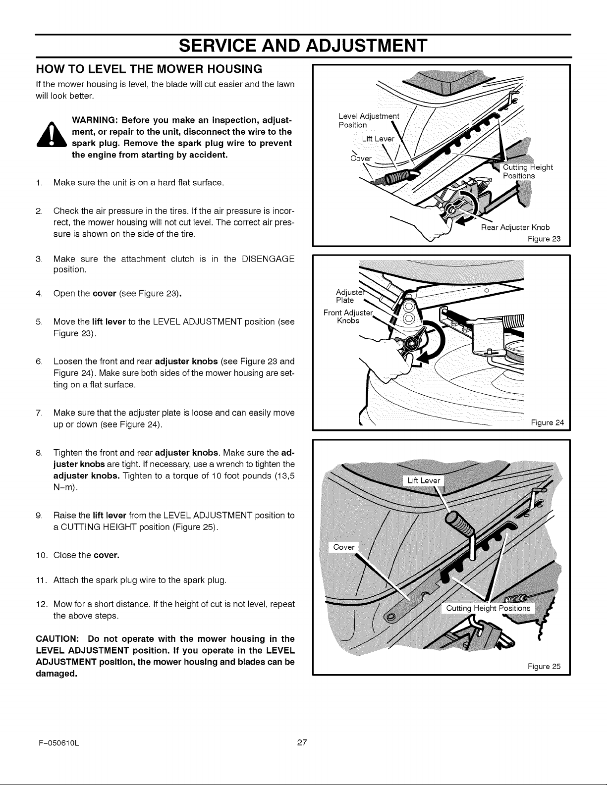
HOW TO CHECK THE SPARK PLUG
1. Check the gap of the spark plug with a feeler gauge
(Figure 22). The correct gap is 0.030".
2. For easy starting and good performance, replace the spark
plug every season or 100 hours of use.
Slots
Feeler Gauge
0.030"
\
Tabs
Cover
Figure 21
F-050610L 26
Spark Plug
Figure 22
SERVICE AND ADJUSTMENT
HOW TO LEVEL THE MOWER HOUSING
If the mower housing is level, the blade will cut easier and the lawn
will look better.
WARNING: Before you make an inspection, adjust-
,_ ment, or repair to the unit, disconnect the wire to the
spark plug. Remove the spark plug wire to prevent
the engine from starting by accident.
1. Make sure the unit is on a hard flat surface.
2. Check the air pressure in the tires. If the air pressure is incor-
rect, the mower housing will not cut level. The correct air pres-
sure is shown on the side of the tire.
3. Make sure the attachment clutch is in the DISENGAGE
position.
4. Open the cover (see Figure 23).
5.
Move the lift lever to the LEVEL ADJUSTMENT position (see
Figure 23).
6.
Loosen the front and rear adjuster knobs (see Figure 23 and
Figure 24). Make sure both sides of the mower housing are set-
ting on a flat surface.
LevelAdjustment
Position
Cover
Plate
Front Adjuster
Knobs
Lift Lever
Cutting Height
Positions
Rear Adjuster Knob
Figure 23
7.
Make sure that the adjuster plate is loose and can easily move
up or down (see Figure 24).
8.
Tighten the front and rear adjuster knobs. Make sure the ad-
juster knobs are tight. If necessary, use a wrench to tighten the
adjuster knobs, Tighten to a torque of 10 foot pounds (13,5
N-m).
9. Raise the lift lever from the LEVEL ADJUSTMENT position to
a CUTTING HEIGHT position (Figure 25).
10. Close the cover,
11. Attach the spark plug wire to the spark plug.
12. Mow for a short distance. If the height of cut is not level, repeat
the above steps.
CAUTION: Do not operate with the mower housing in the
LEVEL ADJUSTMENT position. If you operate in the LEVEL
ADJUSTMENT position, the mower housing and blades can be
damaged.
Figure 24
Figure 25
F-050610L 27
SERVICE AND ADJUSTMENT
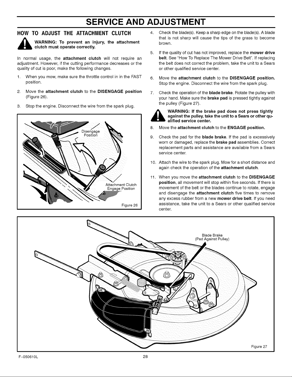
HOW TO ADJUST THE ATTACHMENT CLUTCH
,_ WARNING: To prevent an injury, the attachment
In normal usage, the attachment clutch will not require an
adjustment. However, if the cutting performance decreases or the
quality of cut is poor, make the following changes.
1. When you mow, make sure the throttle control in in the FAST
2.
3. Stop the engine. Disconnect the wire from the spark plug.
clutch must operate correctly.
position.
Move the attachment clutch to the DISENGAGE position
(Figure 26).
4. Check the blade(s). Keep a sharp edge on the blade(s). A blade
that is not sharp wilt cause the tips of the grass to become
brown.
5.
If the quality of cut has not improved, replace the mower drive
belt. See "How To Replace The Mower Drive Belt". If replacing
the belt does not correct the problem, take the unit to a Sears
or other qualified service center.
6.
Move the attachment clutch to the DISENGAGE position.
Stop the engine. Disconnect the wire from the spark plug.
7.
Check the operation of the blade brake. Rotate the pulley with
your hand. Make sure the brake pad is pressed tightly against
the pulley (Figure 27).
,_ WARNING: If the brake pad does not press tightly
against the pulley, take the unit to a Sears or other qu-
alified service center.
8. Move the attachment clutch to the ENGAGE position.
9.
Check the pad for the blade brake. If the pad is excessively
worn or damaged, replace the brake pad assemblies. Correct
replacement parts and assistance are available from a Sears
service center.
10. Attach the wire to the spark plug. Mow for a short distance and
again check the operation of the attachment clutch.
Attachment Clutch
Engage Position
Figure 26
11.
When you move the attachment clutch to the DISENGAGE
position, all movement will stop within five seconds. Ifthere is
movement of the belt or the blades continue to rotate, engage
and disengage the attachment clutch five times to remove
any excess rubber from a new mower drive belt. If you need
assistance, take the unit to a Sears or other qualified service
center.
Blade Brake
(Pad Against Pulley)
F-050610L 28
Figure 27
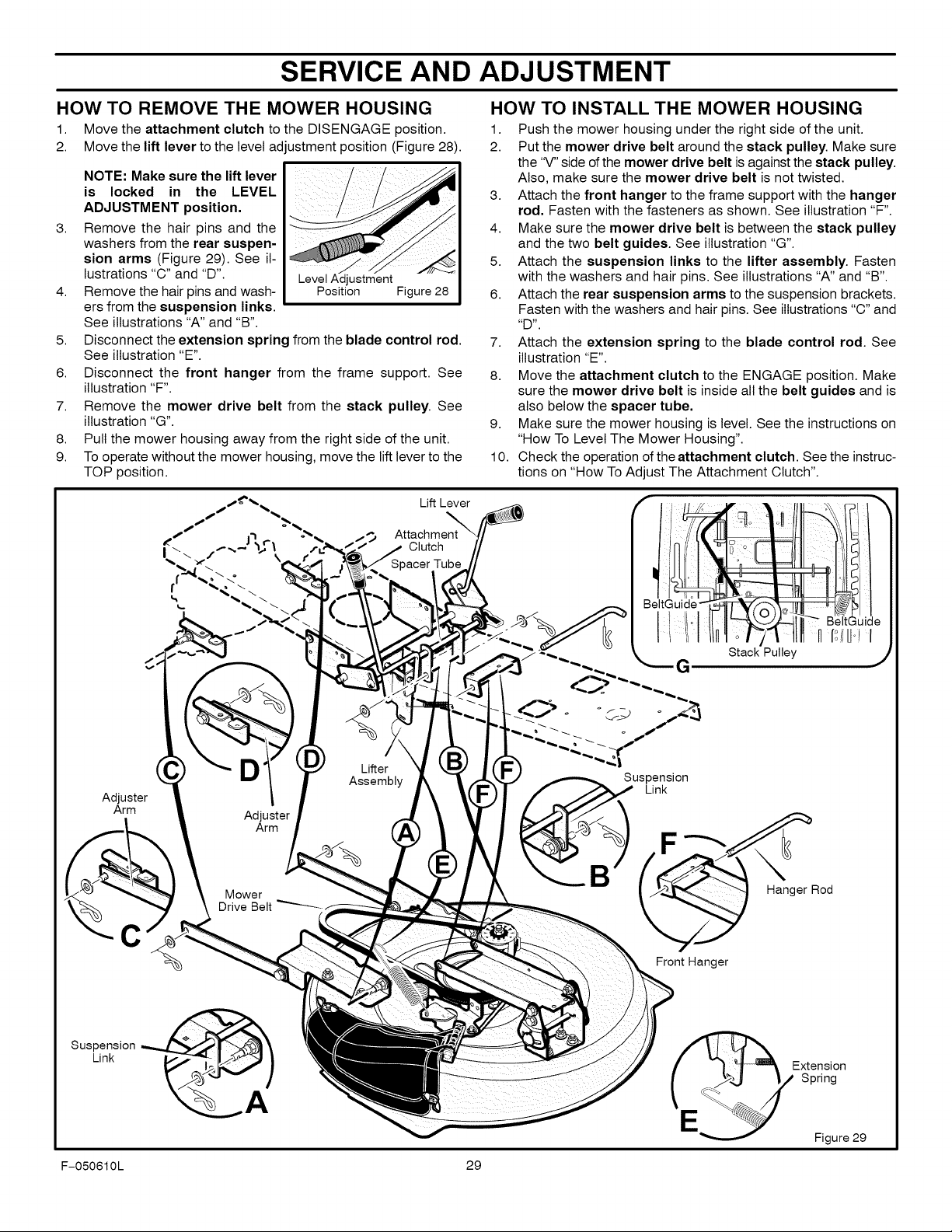
SERVICE AND ADJUSTMENT
1. Move the attachment clutch to the DISENGAGE position.
2. Move the lift lever to the level adjustment position (Figure 28).
NOTE: Make sure the lift lever
is locked in the LEVEL
ADJUSTMENT position.
3.
Remove the hair pins and the
washers from the rear suspen-
sion arms (Figure 29). See il-
lustrations "C" and "D". LevelAdjustment
4.
Remove the hair pins and wash- Position Figure 28
ers from the suspension links.
See illustrations "A" and "B".
5.
Disconnect the extension spring from the blade control rod.
See illustration "E".
6.
Disconnect the front hanger from the frame support. See
illustration "F".
7.
Remove the mower drive belt from the stack pulley. See
illustration "G".
8.
Pull the mower housing away from the right side of the unit.
9.
To operate without the mower housing, move the lift lever to the
TOP position.
Lift Lever
HOW TO INSTALL THE MOWER HOUSINGHOW TO REMOVE THE MOWER HOUSING
1. Push the mower housing under the right side of the unit.
2. Put the mower drive belt around the stack pulley. Make sure
the "V" side of the mower drive belt is against the stack pulley.
Also, make sure the mower drive belt is not twisted.
3. Attach the front hanger to the frame support with the hanger
rod. Fasten with the fasteners as shown. See illustration "F".
4. Make sure the mower drive belt is between the stack pulley
and the two belt guides. See illustration "G".
5. Attach the suspension links to the lifter assembly. Fasten
with the washers and hair pins. See illustrations "A" and "B".
6. Attach the rear suspension arms to the suspension brackets.
Fasten with the washers and hair pins. See illustrations "C" and
_D _"
7. Attach the extension spring to the blade control rod. See
illustration "E".
8. Move the attachment clutch to the ENGAGE position. Make
sure the mower drive belt is inside all the belt guides and is
also below the spacer tube,
9. Make sure the mower housing islevel. See the instructions on
"How To Level The Mower Housing".
10. Check the operation of the attachment clutch. See the instruc-
tions on "How To Adjust The Attachment Clutch".
Adjuster
Arm
C
D
Adjuster
Arm
Mower
Drive Belt
Lifter
Assembly
Attachment
Clutch
_acer Tube
Suspension
Link
Front Hanger
BeltGuide
H f_iilJ'! I
Stack Pulley ,j
Hanger Rod
SuspensionLink
F-050610L 29
Figure 29
SERVICE AND ADJUSTMENT
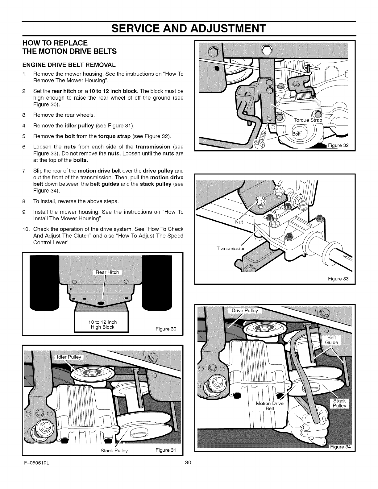
HOW TO REPLACE
THE MOTION DRIVE BELTS
ENGINE DRIVE BELT REMOVAL
1. Remove the mower housing. See the instructions on "How To
Remove The Mower Housing".
2. Set the rear hitch ona 10 to 12 inch block. The block must be
high enough to raise the rear wheel of off the ground (see
Figure 30).
3. Remove the rear wheels.
4,
Remove the idler pulley (see Figure 31).
5.
Remove the bolt from the torque strap (see Figure 32).
6.
Loosen the nuts from each side of the transmission (see
Figure 33). Do not remove the nuts. Loosen until the nuts are
at the top of the bolts.
7,
Slip the rear of the motion drive belt over the drive pulley and
out the front of the transmission. Then, pull the motion drive
belt down between the belt guides and the stack pulley (see
Figure 34).
8,
To install, reverse the above steps.
9.
Install the mower housing. See the instructions on "How To
Install The Mower Housing".
10.
Check the operation of the drive system. See "How To Check
And Adjust The Clutch" and also "How To Adjust The Speed
Control Lever".
Figure 32
Y1V1
Stack Pulley
Figure 30
Figure 31
Figure 33
Figure 34
F-050610L 30
 Loading...