

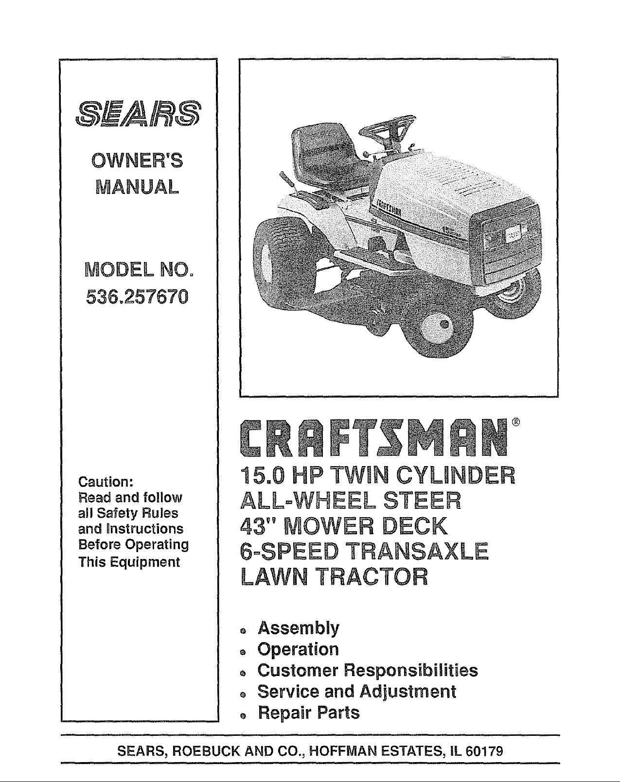
Craftsman 536257670 Owner’s Manual
,,,,, ,,, ,,, --,,,,, ,,,,
Caution:
Read and follow
all Safety Rules
and _nstructions
Before Operating
This Equipment
®
o AssembUy
o Operation
o Customer Responsibilities
o Service and Adjustment
o Repair Parts
=,.,,, ,, ,, ,,
,=,,,,,,,.,,, ,,,,,, ,,, ,,.,, ,,,,,,,,, ,,,
SEARS, ROEBUCK AND CO., HOFFMAN ESTATES, IL 60179
[A SAFETYRUL S
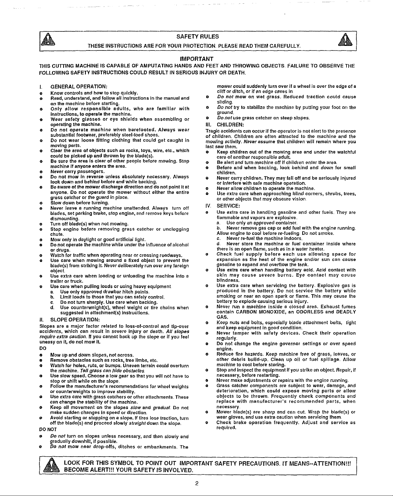
7HIS CUTTING MACHINE IS CAPABLE OF AMPUTATING HANDS AND FEET AND THROWING OBJECTS FAILURE TO OBSERVE THE
FOLLOWING SAFETY INSTRUCTIONS COULD RESULT IN SERIOUS INJURY OR DEATH.
THESE INSTRUCTIONS ARE FOR YOUR PROTECTION. PLEASE READ THEM CAREFULLY.
IMPORTANT
L GENERAL OPERATION:
o Know controls and how to stop qulckty.
• Read, understand, and follow all instructions in the manual and
on the machine before starting,
• Only show responsible adults, who are familiar with
instructions, to operate the machine.
e Wear safety glasses or eye shields when assembling or
operating the machine.
e Do not operate machine when barefooted. Always wear
substantial footwear, preferably steel-toed shoes.
o Do not wear loose fitting clothing that could get caught In
moving parts.
e Clear the area of objects such es rocks, toys, wire, etc., which
could be picked up and thrown by the blade(s).
• Be sure the area Is clear of other people before mowing. Stop
machine if anyone enters the area_
e Never carry passengers°
e Do not mow in reverse unless absolutely necessary, Always
look down and behind before and while backing.
e Be aware of the mower discharge direction and do not point it at
anyone. Do not operate the mower without either the entire
grass catcher or the guard in place
• Slow down before turning_
• Never leave a running machine unattended Atways turn off
blades, set parking brake, stop engine, and remove keys before
dismounting,
• Turn off blade(s) when not mowing.
e Stop engine before removing grass catcher or unclogging
chute.
• Mow only in daylight or good artificial light.
o Do not operate the machine while under the Influence of alcohol
or drugs=
• Watch for traffic when operating near or crossing roadways.
• Use care when mowing around a fixed object to prevent the
blade(s) from striking IL Never deliberately run over any foreign
object.
• Use extra care when loading or unloading the machine into a
trailer or truck,
• Use care when pulling loads or using heavy equipment
a. Use only approved drawbar hitch points.
b. Limit loads to those that you can safely control,
c. Do not turn sharply. Use care when backing.
d Use counterweight(s), wheel weight or tire chains when
suggested in attachment(s) instructions.
IL SLOPE OPERATION:
Slopes are a major factor related to loss-of-control and tip-over
accidents, which can result tn severe injury or death_ All slopes
require extra cautiot_ If you cannot back up the slope or if you feel
uneasy on it, do not mow 1L
DO
® Mow up and down slopes, not across.
• Remove obstacles such as rocks, tree limbs, etc,
e Watch for holes, ruts, or bumps,. Uneven terrain could overturn
the machine, Tall grass can hide obstacles
• Use slow speed. Choose a low gear so that you will not have to
stop or shift while on the slope,
• Follow the manufacturer's recommendations for wheel weights
or counterweights to improve stabgtty_
e Use extra care with grass catchers or other attachmenls These
can change the stability of the machine.
e Keep all movement on the slopes slow and gradual Do not
make sudden changes in speed or direction
o Avoid starting or stopping on a slope. If tires lose traction, turn
off the blade(s) and proceed slowly straight down the slope
DO NOT
• Do net turn on slopes unless necessary, and then slowly and
gradually downhill, if possible=
• Do net mow near dropooffs, ditches or embankments. The
mower could suddenly turn over tf a wheel is over the edge of a
cliff or ditch, or if en edge caves in
e Do not mow on wet grass. Reduced traction couFd cause
sliding.
• Do not try to stabilize the machine by putting your foot c_nthe
ground_
e Do not use grass catcher on steep slopes.
IlL CHILDREN:
Tragic accidents can occur if the operator is not alert to the presence
of children. Children are often attracted to the machine and the
mowing sctlvity_ Never assume that children will remain where you
last saw them.
• Keep children out of the mowtng area and under the watchful
care of another responsible adult,
• Be alert and turn machine off if children enter the area.
e Before and when backing, look behind and down for small
chlldrem
e Never carry children. They may fall off and be seriously Iniured
or interfere with safe machine operation.
• Never allow children to operate the machine.
o Use extra care when approaching blind cornersp shrubs, trees,
or other objects that may obscure vision
IV SERVICE:
• Use extra care in handling gasoline and other fuels They are
flammable and vapors are explosive.
a. Use only an approved container.
b. Never remove gas cap or add fuel with the engine running=
Allow engine to cool before re-fueling Do not smoke
c. Never re-fuel the machine Indoors,
d Never store the machine or fuel container inside where
there is an open flame, such as in a water heater.
o Check fuel supply before each use allowing space for
expansion as the heat of the engine andlor sun can cause
gasoline to expand end overflow the tank.
e Use extra care when harldllng battery acld_ Acid contact with
skin may cause severe burns. Eye contact may cause
blindness.
e Use extra care when servicing the battery Explosive gas is
produced in the battery. Do not service the battery while
smoking or near an open spark or flame. This may cause the
battery to explode causing serious injury.
e Never run a machine inside a closed area. Exhaust fumes
contain CARBON MONOXIDE, an ODORLESS and DEADLY
GAS.
• Keep nuts and bolts, especially blade attachment bolts, tight
and keep equipment in good condition_
e Never tamper with safety devices= Check their operation
regularly_
e Do not change the engine governor settings or over speed
engine.
• Reduce fire hazards. Keep machine free of grass, leaves, or
other debris build=up Clean up oil or fuel spillage_ Allow
machine to cool before storing.
• Stop and inspect the equipment if you strike an object. Repair, if
necessary, before restarting_
• Never make adjustments or repairs with the engine running
• Grass catcher components are subject to wear, damage, end
deterioration, which could expose moving parts or allow
objects to be thrown Frequently check components and
replace with manufacturer's recommended parts, when
necessary
• Mower blade(s) are sharp and can cut Wrap the blade(s) or
wear gloves, and use extra caution when servicing them
e Check brake operation frequently. Adjust and service as
required.
LOOK FOR THIS SYMBOL TO POINT OUT IMPORTANT SAFETY PRECAUTIONS, IT MEANS--ATTENTION!!!
BECOME ALERT!!! YOUR SAFETY IS INVOLVED.
2

CONGRATULATIONS on your purchase of a Sears
Craftsman Tractor It has been designed, engineered
and manufactured to give you the best possible depend-
ability and performance
Should you experience any problem you cannot easily
remedy, please contact your nearest Sears Service
Center/Department We have competent, well-trained
technicians and the proper tools to service or repair this
unit
Please read and retain this manual The instructions will
enabte you to assemble and maintain your tractor
_roperly Always observe the "SAFETY RULES"
MODEL
NUMBER 536257670
SERIAL
NUMBER
DATE OF
PURCHASE
THE MODEL AND SERIAL NUMBERS WILL BE
FOUND ON A PLATE UNDER THE SEAT
YOU SHOULD RECORD BOTH SERIAL NUMBER
AND DATE OF PURCHASE AND KEEP IN ASAFE
PLACE FOR FUTURE REFERENCE
MAgNTENANCE AGREEMENT
A Sears Maintenance Agreement is available on this
product Contact your nearest Sears Store {or details
CUSTOMER RESPONSIBILITIES
o Read and observe safety rules
o Fo{tow a regular schedule in maintaining, caring for and
using your unit
o FOItOw the instructions under"Customer Responsi-
bilities" and "Storage" sections of this manual
PRODUCT SPEClFnCATBONS
HORSE POWER: 15.0
GASOLINE 2 GALLONS
CAPACITY: UNLEADED REGULAR
OIL (30 Pints) SAE 30 - above 32°F
5W - 30" - below 32°F
SPARK PLUG : Champion RJ 19LM
(GAP .030 in.)
VALVE Intake: 004- 006 In
CLEARANCE: Exhaust: .007 - .009 in.
GROUND FORWARD
SPEED: 1st 122 MPH
2nd 2 51 MPH
3rd 3 21 MPH
4th 3 79 MPH
5th 4 76 MPH
6th 5 92 MPH
REVERSE: 2.7O MPH
TIRE PRESSURE: FRONT: 14 PSi
REAR: 10 PSI
CHARGING SYSTEM: 2 4 AMPS @ 3300 RPM
8LADE BOLT TORQUE: 30-35 FT LBS
WARNING: This unit is equipped with an internal com-
bustion engine and should not be used on or near any
unimproved forest-covered, brush+covered or grass-
covered land unless the engine's exhaust system is
equipped with a spark arrester meeting applicable local
or state laws (if any) If a spark arrester is used, it should
be maintained in effective working order by the operator
In the state of California the above is required by law
(Section 4442 of the California Public Resources Code)
Other states may have similar laws Federal laws apply
on federal lands, A spark arrester for the muffler is
available through your nearest Sears Authorized Service
Center (See REPAIR PARTS section in this manual)
CRAFTSMAN ELECTRRC START RIDING EQUIPMENT
UMITED TWO YEAR WARRANTY ON ELECTRIC START RIDING EQUIPMENT
For two (2) years from the date of purchase, if this riding equipment is maintained, lubricated and tuned-up according to the
instructions in the owner's manual, Sears will repair or replace, any parts found to be defective in material or workmanship
This warranty does not cover:
o Expendable items which become worn during norma! use, such as blades, spark plugs, air cleaners and belts
o Tire replacement or repair caused by punctures from outside objects, such as nai!s, thorns, stumps, or glass
• Repairs necessary because of operator abuse, negligence, improper storage or accident or the failure to maintain the
equipment according to the instructions contained in the operator's manual
Riding equipment used for commercial or rental purposes
LIMITED 90 DAY WARRANTY ON BATTERY
For 90days from the date of purchase, ifany battery includedwith this riding equipment proves defective in materia!or
workmanship and our testing determines the battery will not hold a charge, Sears will replace the battery at nocharge
WARRANTY SERVICE IS AVAILABLE BY RETURNINGTHE RIDING EQUIPMENT TO THE NEAREST SEARS SERVICE
CENTER/DEPARTMENT iNTHE UNITEDSTATES
This warranty gives you specific legal rights, and you may also have other rights which may vary from state to
state
SEARS, ROEBUCK AND CO , D/817WA, HOFFMAN ESTATES, IL 60179
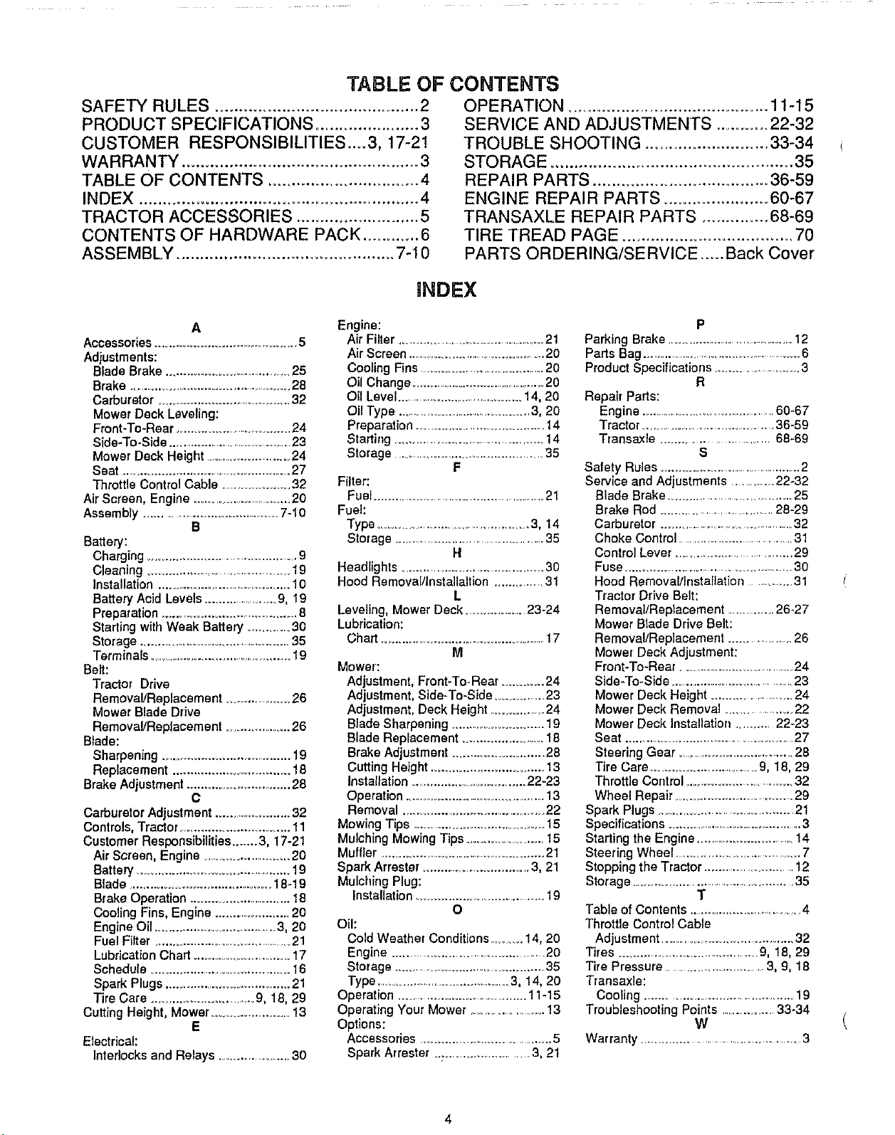
TABLE OF CONTENTS
SAFETY RULES ............................................ 2
PRODUCT SPECIFICATIONS ...................... 3
CUSTOMER RESPONSIBILITIES__3, 17-21
WARRANTY .................................................. 3
TABLE OF CONTENTS ................................ 4
INDEX ........................................................... 4
TRACTOR ACCESSORIES .......................... 5
CONTENTS OF HARDWARE PACK ............ 6
ASSEMBLY .............................................. 7-I0
OPERATION ........................................... 11-15
SERVICE AND ADJUSTMENTS ........... 22-32
TROUBLE SHOOTING .......................... 33-34
STORAGE ................................................... 35
REPAIR PARTS ..................................... 36-59
ENGINE REPAIR PARTS ...................... 60-67
TRANSAXLE REPAIR PARTS .............. 68-69
TIRE TREAD PAGE .................................... 70
PARTS ORDERING/SERVICE ..... Back Cover
iNDEX
A
Accessories ..................................................5
Adjustments:
Blade Brake ........................................25
Brake .....................................................28
Carburetor ..............................................32
Mower Deck Leveling:
Front-To-Rear .....................................24
Side-To-Side .............................................23
Mower Deck Height ..............................24
Seat .........................................................27
Throttle Control Cable ..........................32
Air Screen, Engine .................................20
Assembly .............................................7-10
B
Battery:
Charging ............................................. 9
Cleaning ..............................................19
Installation ............................................10
Battery Acid Levels .......................9, 19
Preparation .......................................... 8
Starting wilt] Weak Battery ............ 30
Storage .............................................. 35
Terminals ........................................... 19
Belt:
Tractor Drive
Removal/Replacement ......................26
Mower Blade Drive
Removal/Replacement ....................26
Blade:
Sharpening .........................................19
Replacement .................................. 18
Brake Adjustment ................................ 28
C
Carburetor Adjustment ..........................32
Controls, Tractor ............................... 11
Customer Responsibilities ....... 3, 17-21
Air Screen, Engine ...........................20
Battery .............................................. 19
Blade .......................................... 18-19
Brake Operation ................................18
Cooling Fins, Engine ..........................20
Engine Oil ........................................3, 20
Fuel Filter .............................................21
Lubrication Chart ..................................17
Schedule .......................................... 16
Spark Plugs ....................................... 21
Tire Care .....................................9, 18, 29
Cutting Height, Mower ......................... 13
E
Electrical:
Interlocks and Relays ..................... 30
Engine:
Air Filter ..................................................21
Air Screen ...............................................20
Cooling Fins ............................................20
Oil Change ...............................................20
Oil Level .............................................14, 20
Oil Type .............................................3, 20
Preparation ............................................14
Starting ..................................................14
Storage .....................................................35
F
Filter:
Fuel .......................................................21
Fuel:
Type ........................................................3, 14
Storage .............................................. 35
H
Headlights ........................................... 30
Hood RemovalllnstaUaltion ................31
L
Leveling, Mower Deck ......................23-24
Lubrication:
Chart ......................................................... 17
M
Mower:
Adjustment, Front-To-Rear ............. 24
Adjustment, Side-To-Side ................23
Adjustment, Deck Height ...................24
Blade Sharpening ................................19
Blade Replacement ....................... 18
Brake Adjustment ..............................28
Cutting Height .................................. 13
Installation ..................................... 22+23
Operation ..................................................13
Removal ........................................... 22
Mowing Tips ......................................... 15
Mulching Mowing Tips .......................... 15
Muffler .................................................... 21
Spark Arrestar .................................. 3, 21
Mulching Plug:
Installation .......................................... 19
O
Oil:
Cold Weather Conditions ...........14, 20
Engine .............................................. 20
Storage ................................................ 3 5
Type .......................................... 3, 14, 20
Operation ....................................... 11-15
Operating Your Mower ......................... 13
Options:
Accessories .......................................... 5
Spark Arrester ........................... 3, 2t
P
Parking Brake .......................................... 12
Parts Bag .............................................................6
Product Specificatio[ls ..............................3
R
Repair Parts:
Engine ..............................................60-67
Tractor ..............................................36-59
Transaxle .............................. 68-69
S
Safety Rules ......................................... 2
Service and Adjustments ..............22+32
Blade Brake ..........................................25
Brake Rod ......................................28-29
Carburetor ............................................32
Choke Control ....................................31
Control Lever ................................. 29
Fuse ...................................................... 30
Hood Removal/Installation ..............31
Tractor Drive Belt:
Removal/Replacement ............. 26-27
Mower Blade Drive Belt:
Removal/Replacement ...................... 26
Mower Deck Adjustment:
Front-To-Rear ........................................24
Side-To-Side ...........................................23
Mower Deck Height ...........................24
Mower Deck Removal ................... 22
Mower Deck Installation .............22-23
Seat .................................................... 27
Steering Gear ...................................... 28
Tire Care .................................. 9, 18, 29
Throttle Control ................................. 32
Wheel Repair+ .................................... 29
Spark Plugs ............................................. 21
Specifications ...............................................3
Starting the Engine ....................................14
Steering Wheel ..........................................7
Stopping the Tractor ............................. 12
Storage .......................................................35
T
Table of Contents .................................. 4
Throttle Control Cable
Adjustment ..............................................32
Tires .............................................9, 18, 29
Tire Pressure .............................. 3, 9, 18
Transaxle:
Cooling ........................................... 19
Troubleshooting Points ................. 33-34
W
Warranty ................................................ 3
4
ii
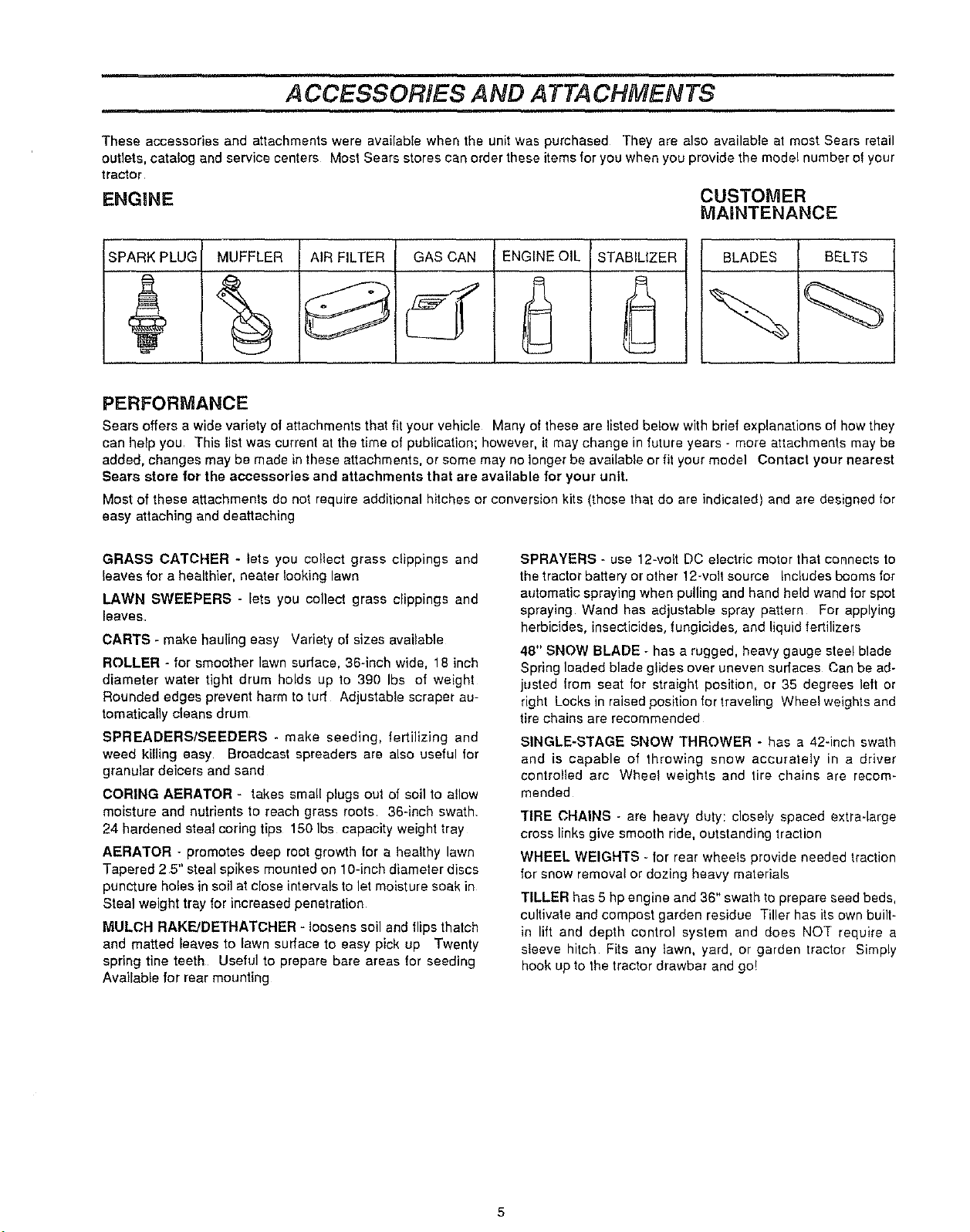
ACCESSORIES AND A TTA CHMEN TS
These accessories and attachments were availabfe when the unit was purchased They are also available at most Sears retail
outlets, catalog and service centers Most Sears stores can order these items for you when you provide the model number ol your
tractor
ENGmNE
CUSTOMER
MAINTENANCE
SPARK PLUG MUFFLER AIR FILTER GAS CAN ENGINE OIL
STABILIZER
BLADES BELTS
PERFORMANCE
Sears offers a wide variety of attachments that fit your vehicle Many of these are listed below with brief explanations of how they
can help you This list was current at the time of publication; however, it may change in future years - more attachments may be
added_changesmayb_madeintheseattachrnents__rs_memayn___ngerbeavai_ab_eorfi_y_urm_de_ Contact your nearest
Sears store for the accessories and attachments that are available for your unit.
Most of these attachments do not require additional hitches or conversion kits (those that do are indicated) and are designed lot
easy attaching and deattaching
GRASS CATCHER - lets you collect grass clippings and
leaves for a healthier, heater looking lawn
LAWN SWEEPERS - lets you collect grass clippings and
leaves
CARTS - make hauling easy Variety of sizes available
ROLLER - for smoother lawn surface, 36-inch wide, 18 inch
diameter water tight drum holds up to 390 Ibs of weight
Rounded edges prevent harm to turf Adjustable scraper au-
tomatically cleans drum
SPREADERS/SEEDERS - make seeding, tertilizing and
weed killing easy Broadcast spreaders are also useful for
granular deicers and sand
CORING AERATOR - takes small plugs out of soil to allow
moisture and nutrients to reach grass roots 36-inch swath
24 hardened steal coring tips 150 Ibs capacity weight tray
AERATOR - promotes deep root growth for a healthy lawn
Tapered 2 5" steal spikes mounted on 10-inch diameter discs
puncture holes in soil at close intervals to let moisture soak in
Steal weight tray for increased penetration
MULCH RAKFJDETHATCHER - loosens soil and flips thatch
and matted leaves to lawn surface to easy pick up Twenty
spring tine teeth Useful to prepare bare areas !or seeding
Available for rear mounting
SPRAYERS - use 12-volt DC electric motor that connects to
the tractor battery or other !2-volt source Includes booms lot
automatic spraying when pulling and hand held wand for spot
spraying Wand has adjustable spray pattern For applying
herbicides, insecticides, fungicides, and liquid fertilizers
48" SNOW BLADE - has a rugged, heavy gauge steel blade
Spring loaded blade glides over uneven surfaces Can be ad-
justed from seat for straight position, or 35 degrees left or
right Locks in raised position for traveling Wheel weights and
tire chains are recommended
SINGLE-STAGE SNOW THROWER - has a 42-inch swath
and is capable of throwing snow accuralety in a driver
controlled are Wheel weights and tire chains are recom-
mended
TIRE CHAINS - are heavy duty: closely spaced extra-large
cross links give smooth ride, outstanding traction
WHEEL WEIGHTS - for rear wheels provide needed traction
for snow removal or dozing heavy materials
TILLER has 5 hp engine and 36" swath to prepare seed beds,
cultivate and compost garden residue Tiller has its own built-
in lift and depth control system and does NOT require a
sleeve hitch Fits any lawn, yard, or garden tractor Simply
hook up to the tractor drawbar and go!
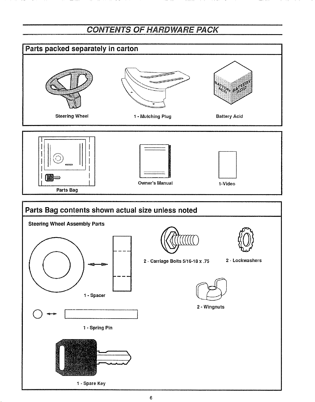
CONTENTS OF HARDWARE PACK
Parts packed separately in carton
Steering Wheel
1 - Mulching Plug
@
Owner's Manual
Parts Bag
Parts Bag contents shown actual size unless noted
Steering Wheel Assembly Parts
2. Carriage Bolts 5/16-18 x =75
Battery Acid
1-Video
®
2 - Lockwashers
1 - Spacer
1 - Spring Pin
1 - Spare Key
2 - Wingnuts
6
ASSEMBLY
TOOLS REQUIRED FOR ASSEMBLY
A socket wrench will make assembly easier Standard wrench
sizes are listed.
(1) Pliers
(1) Utility knife
(1) Screwdriver (Small Phillips with a 1/4 inch shank)
(1) Hammer
(1) Tire pressure gauge
(2) 7/16 inch wrenches
(2) 1/2 inch wrench
(1) Tape measure
When right and left hand is mentioned in this manuat, if
means when you are in the operating position (seated behind
the steering wheel)
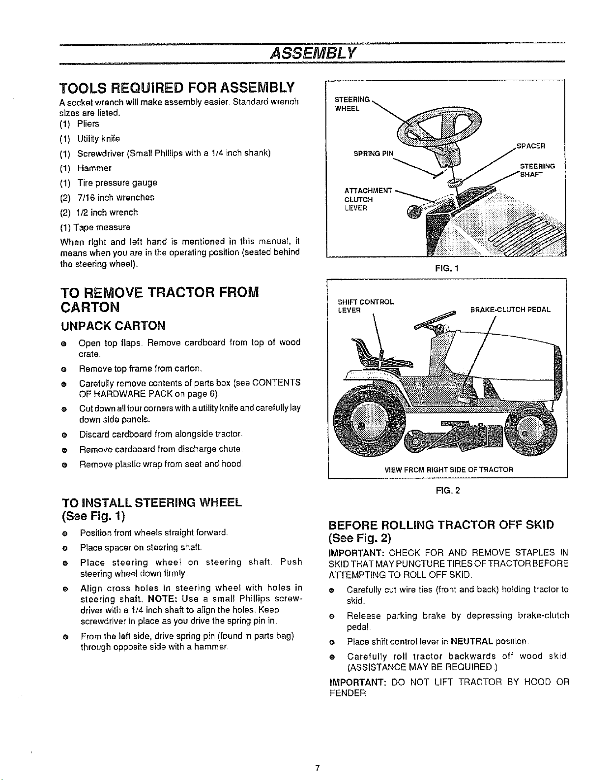
STEERING
WHEEL
SPRING PIN
CLUTCH
LEVER
SPACER
STEERING
FIG. 1
TO REMOVE TRACTOR FROM
CARTON
UNPACK CARTON
e Open top flaps Remove cardboard from top of wood
crate.
e Remove top frame from carton
e, Carefully remove contents of parts box (see CONTENTS
OF HARDWARE PACK on page 6).
e Cut down allfour corners with a utility knife and carefully lay
down side panels+
e Discard cardboard from alongside tractor
o Remove cardboard from discharge chute
e Remove plastic wrap from seat and hood
TO INSTALL STEERING WHEEL
(See Fig. 1)
e Position front wheels straight forwar&
e Place spacer on steering shaft.
e,
Place steering wheel on steering shaft Push
steering wheel down firmly
o
Align cross holes in steering wheel with holes in
steering shaft, NOTE: Use a small Phillips screw-
driver with a 1/4 inch shaft to align the holes Keep
screwdriver in place as you drive the spring pin in
e From the left side, ddve spring pin (found in parts bag)
through opposite side with a hammer
SHIFT CONTROL
LEVER
VIEW FROM RIGHT SIDE OF TRACTOR
FIG, 2
BRAKE_;LUTCHPEDAL
BEFORE ROLLING TRACTOR OFF SKID
(See Fig. 2)
IMPORTANT: CHECK FOR AND REMOVE STAPLES IN
SKID THAT MAY PUNCTURE TIRES OF TRACTOR BEFORE
ATTEMPTING TO ROLL OFF SKID
• Carefully cut wire ties (front and back) holding tractor to
skid
e Release parking brake by depressing brake-clutch
peda!.
e Place shift contro! lever in NEUTRAL position
e Carefully roll tractor backwards off wood skid
(ASSISTANCE MAY BE REQUIRED )
IMPORTANT: DO NOT LIFT TRACTOR BY HOOD OR
FENDER

A SSEMBL Y
HOW TO SET UP YOUR TRACTOR
PREPARE BATTERY
For shipping purposes, battery is installed Remove battery
(see TO REMOVE BATTERY instructions below)
CAUTION: Wear eye and face shield.
Wash hands or clothing immediately if
acc!dentally in contact with battery acid
Do not smoke,, Fumes from charged battery acid are
explosive,
Follow the CAUTIONS located on the battery. Al-
ways wear gloves, clothing and goggles to protect
your hands, skin and eyes.
TO REMOVE BATTERY (See Fig 3) -
e Lift seat.
e Disconnect negative (-) black battery cable with a 7/16"
wrench
e Slide battery boot away from positive (+) battery terminal
and disconnect positive (+) red battery cable with a 7/16"
wrench
• Remove plastic wing nut from battery hold-down
rod. NOTE: Lay aside for battery installation later
• Remove battery hold-down rod and battery hold-down
bracket, NOTE: Lay aside for battery installation later
• Lift batteIy out of tractor
e Place battery on level surface
e Proceed TO ACTIVATE THE BATTERY instructions
DANGER
Always disconnect negative (black) cable first.
Removing positive cable first can result in sparks if
the wrench touches any metal surface. Be sure
battery hold-down bracket does not touch battery
terminals and cause a spark_
TO ACTIVATE THE BATTERY (See Fig 4) -
e Remove vent caps from battery
e Fill battery with battery acid Fill each cell until it
reaches bottom of vent wells Do not over fill
e Allow battery to stand and settle for at least thirty
minutes and then check leve! of acid If acid is
below level outlined on electrolyte package, add more
acid until correct level is reached
IMPORTANT: TO MAXIMIZE LIFE OF YOUR BATTERY,
IT IS NECESSARY THE BATTERY BE CHARGED BEFORE
USE FAILURE TO CHARGE BATTERY CAN RESULT iN
SHORTENED BATTERY LIFE
VENTCAP
VENT
BATTERY
CELL ACID
.. • LEVEL
CUT*AWAY VIEW OF BA37"ERY
FIG. 4
WELL
NEGATIVEBLACK
BATTERYCABLE
BATTERY HOLD-DOWN BRACKET
1/4 X 3/4 INCH HEX HEAD SCREW
BATTERY
BOOT
POSI'[IVE (+) BATTERY TERMINAL BATTERY BOOT POSITIVE 1+} RED BATTERY CABLE
CUT-AWAY VIEW FROM RIGHT-HAND SIDE OF TRACTOR
NUT
NEGATIVE(-) BATTERy TERMINAL
\
NEGATIVE (,) BLACK
BATTERY CABLE
BA3-FERY
HOLD-DOWN
_ ROD
FIG_3
ASSEMBLY
CAUTION: Handle electrolyte with care°
It is an acid and poison. Always wear eye
shields, and protect skin when handling
acid or battery°
POISON - CAUSES SEVERE BURNS
Contains sulfuric acid.
Avoid contact with skin, eyes or clothing.
To prevent accidents, neutralize excess acid with
baking soda and rinse empty container with water,.
TREATMENT:
EXTERNAL - Flush with water,.
iNTERNAL - Drink large quantities of water or milk.
Follow with milk of magnesia, beaten eggs or
vegetable oil. Call physician immBdiately..
EYES - Flush with water for 15 minutes and get
prompt medical attention°
KEEP OUT OF THE REACH OF CHILDREN
Charge battery at a rate of six (6) amps for 1 hour
Use a 12-volt battery charger Observe all safety
precautions required for battery charging Complete as-
sembly section of this manual while waiting for battery to
charge,
Check acid level after the battery is charged If
acid has fallen below correct level, add distilled or iron
free water
e Install vent caps to cover vent wells, Wash top of battery
with water to remove any acid, then wipe dry
o Check battery case for leakage to make sure that no
damage has occurred in handling,
@
Dispose of excess battery acid Neutralize acid for dis-
posal by adding it to four inches of water in a five (5) gal-
lon plastic container Stir with a wooden or plastic paddle
while adding baking soda until the addition of more soda
causes no more foaming
CHECK TIRE PRESSURE
For shipping purposes, the tires on your tractor were over-in-
flated at the factory Correct tire pressure is important for best
cutting performance
e Remove hub caps by placing two fingers in hole in each
cap and pulling them from the wheels
e Use tire pressure gauge to check amount of air in tires
e Reduce tire pressure to PSi shown in "PRODUCT
SPECIFICATIONS" on page 3 of this manual
• Replace hub caps Position on wheels and push firmly
CHECK FOR PROPER POSITION OF ALL
BELTS
• See figures shown for replacing motion and mower blade
drive belts in SERVICE AND ADJUSTMENTS
section of this manual Verify belts are routed correctly
TO LEVEL MOWER DECK
For best cutting results the mower deck has been leveled at the
factory and should not require any adjustment If in the event
the deck should need to be adjusted see TO LEVEL MOWER
DECK in the SERVICE AND ADJUSTMENTS section of this
manual
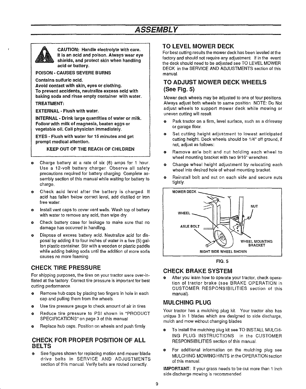
TO ADJUST MOWER DECK WHEELS
(See Fig. 5)
Mower deck wheels may be adjusted to one of four positions
Always adjust both wheels to same position NOTE: Do Not
adjust wheels to support mower deck while mowing or
uneven cutting will result
e Park tractor on a firm, level surface, such as a driveway
or garage floor
O
Set cutting height adjustment to lowest anticipated
cutting height Deck wheels should be 1/4" off ground, if
not, adjust as follows:
0
Remove axle bolt and nut holding each wheel to
wheel mounting bracket with two 9/16" wrenches,
0
Change wheel height adjustment by relocating each
wheel into desired hole of wheel mounting bracket
0
Reinstall bolt and nut on each side and secure nuts
tightly
MOWER
/
AXLE BOLT
NUT
\
WHEEL MOUNTING
BRACKET
RIGHT SIDE WHEEL SHOWN
FIG,, 5
CHECK BRAKE SYSTEM
e After you learn how to operate your tractor, check opera-
tion of tractor brake (see BRAKE OPERATION in
CUSTOMER RESPONSIBILITIES section of this
manual).
MULCHING PLUG
Your tractor has a mulching plug kit Your tractor also has
unique 3 in t blades which are designed to side discharge,
mulch and mow without changing blades
e To install the mulching plug kit see TO INSTALL MULCH-
ING PLUG INSTRUCTIONS in the CUSTOMER
RESPONSIBILITIES section of this manual,
o For additional information on the mulching plug see
MULCHING MOWING HINTS inthe OPERATION section
of this manual
IMPORTANT: if your grass needs to be cut more than 1 inch
side discharge mowing is recommended
9
ASSEMBL Y
DANGER
Always connect positive (red) cable firsL Connect-
ing negative cable first can result in sparks if the
wrench touches any metal surface. Be sure battery
hold-down bracket does not touch battery terminals
and cause a spark.
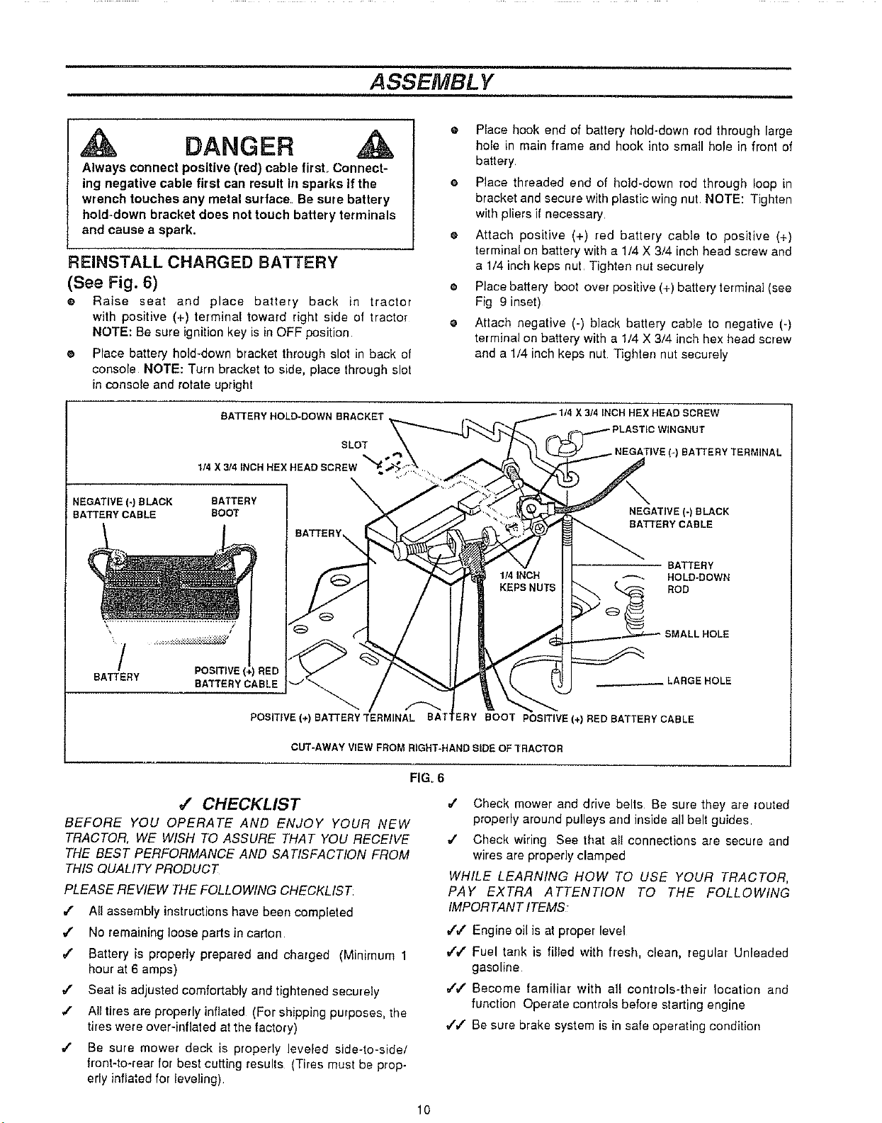
REINSTALL CHARGED BATTERY
(See Fig. 6)
® Raise seat and place battery back in tractor
with positive (+) terminal toward right side of tractor
NOTE: Be sure ignition key is in OFF position
e Place battery hold-down bracket through slot in back of
console NOTE: Turn bracket to side, place through slot
in console and rotate upright
@
Place hook end of battery hold-down rod through large
hole in main frame and hook into small hole in front of
battery
Place threaded end of hold-down rod through loop in
bracket and secure with plastic wing nut NOTE: Tighten
with pliers if necessary
Attach positive (+) red battery cable to positive (+)
terminal on battery with a 1/4 X 3/4 inch head screw and
a 1/4 inch keps nut Tighten nut securely
@
Place battery boot over positive (+) battery terminal (see
Fig 9 inset)
@
Attach negative (-) black battery cabte to negative (-)
terminal on battery with a 1/4 X 3/4 inch hex head screw
and a 1/4 inch keps nut Tightee nut securely
BATTERY HOLD-DOWN BRACKET
SLOT
1/4 X 3/4 INCH HBX HEAD SCREW
NEGATIVE (-) BLACK BATTERy
BATTERY CABLE BOOT
"# POSITIVE (4 _RED
BA'I_ERY
BATTERY CABLE
POSITIVE (+) BATTERY TERMINAL
CUT.AWAY VIEW FROM RIGHT-HAND SIDE OF TRACTOR
\
,,/ CHECKLIST
BEFORE YOU OPERATE AND ENJOY YOUR NEW
TRACTOR, WE WISH TO ASSURE THAT YOU RECEIVE
THE BEST PERFORMANCE AND SATISFACTION FROM
THIS QUALITY PRODUCT
PLEASE REVIEW THE FOLLOWING CHECKLIS T:
/ All assembly instructions have beer completed
_f No remaining loose parts in carton
/ Battery is properly prepared and charged (Minimum 1
hour at 6 amps)
,f Seat is adjusted comfortably and tightened securely
,,t All tires are properly inflated (For shipping purposes, the
tires were over-inflated at the factory)
#" Be sure mower deck is properly leveled side-to-side/
front-to-rear for best cutting results (Tires must be prop-
erly inflated for leveling)
X 3/4 INCH HEX HEAD SCREW
(-) BATTERY TERMINAL
NEGATIVE (-) BLACK
BATIBRY CABLE
BATTERY
HOLD-DOWN
ROD
_LARGE HOLE
'ERY BOOT POSITIVE (+) RED BATTERY CABLE
FIGo6
,/ Check mower and drive belts Be sure they are routed
properly around pulleys and inside all belt guides
/ Check wiring See that all connections are secure and
wires are properly clamped
WHILE LEARNING HOW TO USE YOUR TRACTOR,
PAY EXTRA ATTENTION TO THE FOLLOWING
IMPOR TANT ITEMS;
#V Engine oil is at proper level
4'#' Fuel tank is filled with fresh, clean, regular Unleaded
gasoline
,t',/ Become familiar with aI! controls-their location and
function Operate controls before starting engine
,(/" Be sure brake system is in safe operating condition
10
OPERATION
.....,i
KNOW YOUR TRACTOR
READ THiS OWNER'S MANUAL AND SAFETY RULES BEFORE OPERATING YOUR
TRACTOR
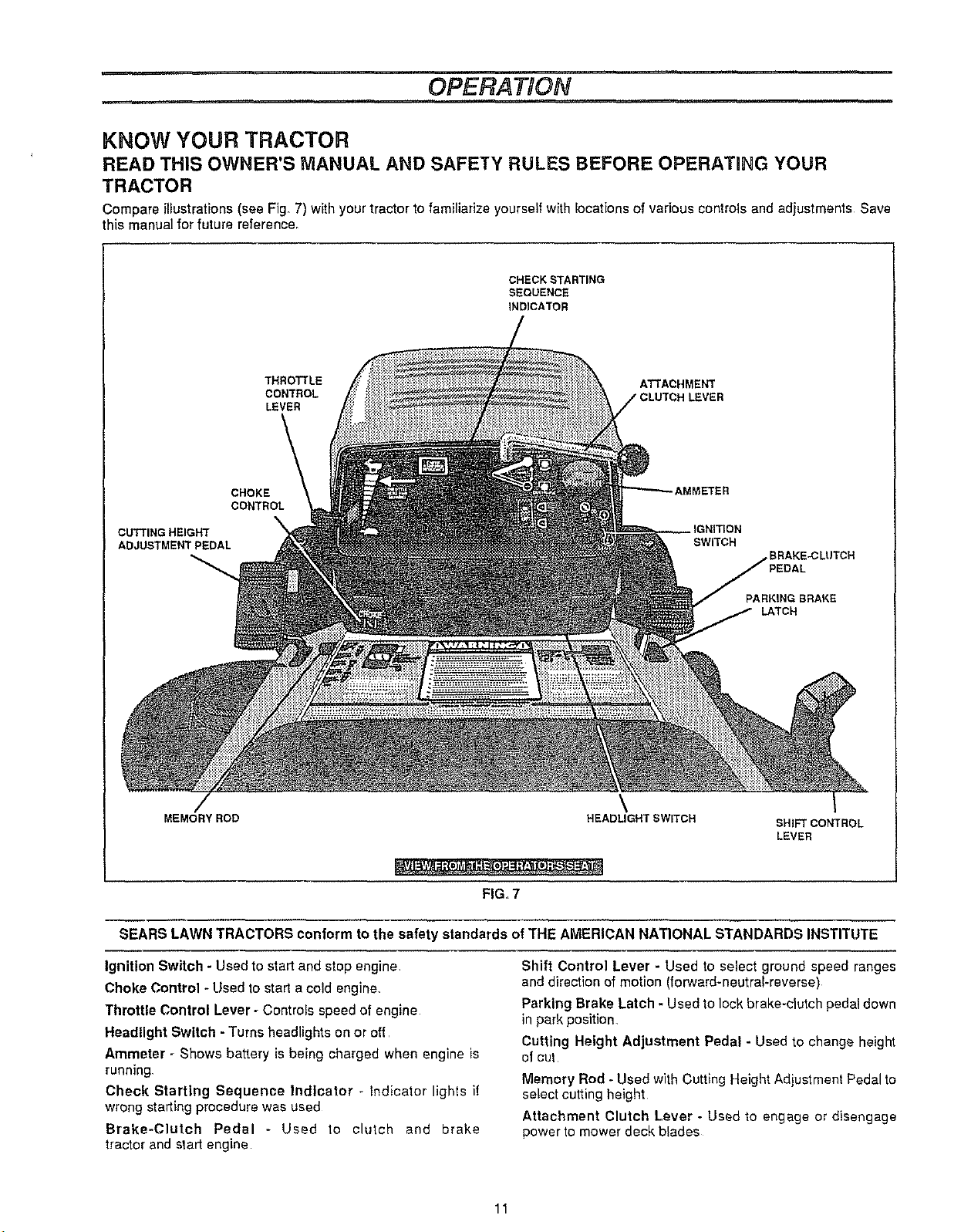
Compare illustrations (see Fig. 7) with your tractor to familiarize yourself with !ocations of various controls and adjustments Save
this manual for future reference,
CHECK STARTING
SEQUENCE
INDICATOR
THRO'I3"LE ATTACHMENT
CONTROL LEVER
LEVER
AMMETER
SWITCH
BRAKE_LUTCH
PARKING BRAKE
LATCH
i
SHIFT CONTROL
LEVER
CUTTING HEIGHT
ADJUSTMENT PEDAL
MEMORYROD
CHOKE
CONTROL
\
HEADLIGHT SWITCH
.= o,., =. ,
FIG,7
SEARS LAWN TRACTORS conform to the safety standards of THE AMERICAN NATIONAL STANDARDS INSTITUTE
Ignition Switch - Used to start and stop engine
Choke Control - Used to start a cold engine_
Throttle Control Lever - Controls speed of engine
Headlight Switch - Turns headlights on or off
Ammeter - Shows battery is being charged when engine is
running
Check Starting Sequence Indicator - Indicator lights if
wrong starting procedure was used
Brake-Clutch Pedal - Used to clutch and brake
tractor and start engine
Shift Control Lever - Used to select ground speed ranges
and direction of motion (forward-neutral-reverse)
Parking Brake Latch - Used to lock brake-crutch pedal down
in park position,
Cutting Height Adjustment Pedal - Used to change height
of cut
Memory Rod - Used with Cutting Height Adjustment Pedal to
select cutting height
Attachment Clutch Lever - Used to engage or disengage
power to mower deck blades
11
OPERA.ON
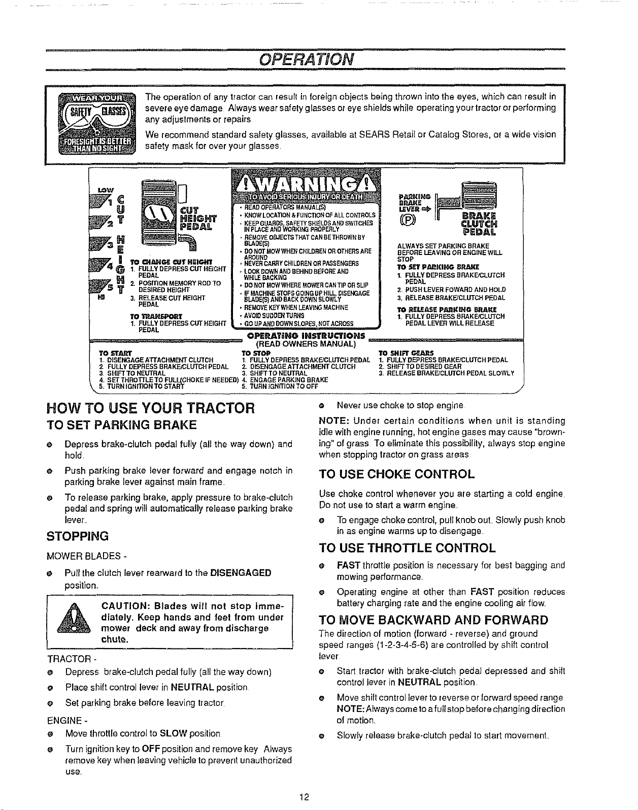
The operation of any tractor can result in foreign objects being thrown into the eyes, which can result in
severe eye damage Always wear safety glasses or eye shields while operating your tractor or performing
any adjustments or repairs
We recommend standard safety glasses, available at SEARS Retail or Catalog Stores, or a wide vision
safety mask for over your glasses
LOW
• READOPERATORSMANUAL(S)
• KNOWLOCATION&FUNCnONOFALLCONTROLS
T HEIGHT
1. FULLY DEPRESS CUT HEIGHT
PEDAL
_ 2, POSITIONMEMORYRODTO
...................................... (READ OWNERS MANUAL)
TO START TO STOP TO SHIFT G_auzs
1 DISENGAGE ATTACHMENTCLUTCH 1 FULLYDEPRESS SRARFJCLUTCHPEDAL 1 FULLY DEPRESS BRAKE/CLUTCH PEDAL
2 FULLYDEPRESSBEAKFJCLUTCHPEDAL 2 D_SENGAGEATTACHMENTCLUTCH B SHIFTTODESIREDGEAR
3 SHJFTTO NEUTRAL 3 SHIFTTO NEUTRAL 3 RELEASEBRAKE/CLUTCH PEDALSLOWLY
4 SET THROTTLETO FULL(CHOKE IFNEEDED) 4. ENGAGE PARKING BRAKE
S TURN IGNITION TO START S. TURN IGNITIONTO OFF
DESIRED HEIGHT
3, RELEASECUT HEIGHT
PEDAL
TO_
1, FULLY DEPRESS CUTHEIGHT
PEDAL
P_DAL
KEEPGUARDSSAREWSHIELDSANDSWITCHES
INPLACEAND_ORKINGPROPERLY
. REMOVEOBJECTSTHATCANBETHROWNBY
BLADE(S)
• DONOTMeWWHENCHILDRENOROTHERSARE
AROUND
• NEVERCARRYCHILDRENORPASSENGERS
LOOKDOWNANDBEHINDBEFOREAND
WHILEBACKING
• DONOTMOWWHEREMOWERCANTiP ORSLiP
. IFMACHINESTOPSGOINGUPRILL.DISENGAGE
DLADEIS) ANDBACKSOWNSLOI_/LY
• REMOVEKEYWHENLEAVINGMACHINE
• AVOIDSUDDENTURNS
• GOUPANDDOWNSLOPES,NOTACROSS
OPEP, JT_HG INSTRUCTIONS ..............
EP,AKE
(,_ Ig BRAKE
CLUTCH
PEDAL
ALWAYSSET PARKING BRAKE
BEFORELEAVINGOR ENGINE WILL
STOP
TO SET PAJ_KING BRAKE
1, FULLYDEPRESS BRAKE/CLUTCH
PEDAL
2 PUSH LEVERFOWARD AND HOLD
3, RELEASEBRAKE/CLUTCH PEDAL
TO P.EESJL_EPAJ_K_G BP.J},KE
I FULLYDEPRESS BRAKEtCLUTCH
PEDAL LEVERWILL RELEASE
HOW TO USE YOUR TRACTOR
TO SET PARKING BRAKE
e Depress brake.clutch pedal fully (all the way down) and
hold.
e Push parking brake lever forward and engage notch in
parking brake lever against main frame
• To release parking brake, apply pressure to brake-clutch
pedal and spring will automatically release parking brake
lever.
STOPPING
MOWERBLADES -
e Pullthe clutch lever rearward to the DISENGAGED
position_
diately. Keep hands and feet from under
[A no,.,o [
TRACTOR -
o Depress brake-clutch pedal fully (all the way down)
e Place shift control lever in NEUTRAL position
e Set parking brake before leaving tractor
ENGINE -
e Movethrottlecontrolto SLOW position
e Turnignition keyto OFFposition andremovekey Always
removekey when leavingvehicle to preventunauthorized
use,
mower deck and away from discharge
chute•
• Never use choke to stop engine
NOTE: Under certain conditions when unit is standing
idle with engine running, hot engine gases may cause "brown-
ing"of grass To eliminate this possibility, always stop engine
when stopping tractor on grass areas
TO USE CHOKE CONTROL
Use choke control whenever you are starting a cold engine
Do not use to start a warm engine
e To engage choke control, pull knob out Slowly push knob
in as engine warms up to disengage
TO USE THROTTLE CONTROL
FAST throttle position is necessary for best bagging and
mowing performance
e Operating engine at other than FAST position reduces
battery charging rate and the engine cooling air flow.
TO MOVE BACKWARD AND FORWARD
The direction of motion (forward - reverse) and ground
speed ranges (1-2-3-4-5-6) are controlled by shift control
lever
e Start tractor with brake-clutch pedal depressed and shift
control lever in NEUTRAL position
e Move shift control lever to reverse or forward speed range
NOTE: Always corn e toafull stop before chang ins direction
of motion
e Slowly release brake-clutch pedal to start movement
12
OPERATION
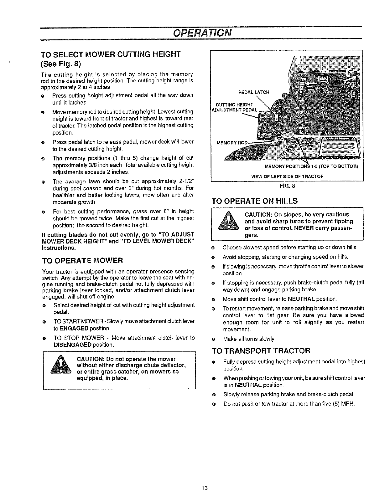
TO SELECT MOWER CUTTING HEIGHT
(See Fig. 8)
The cutting height is selected by placing the memory
rod in the desired height position The cutting height range is
approximately 2 to 4 inches
e Press cutting height adjustment pedal all the way down
until it latches
O Move memory rod to desired cutting height. Lowest cutting
height is toward front of tractor and highest is toward rear
of tractor, The latched pedal position is the highest cutting
position.
e Press pedal latch to release pedal, mower deck will lower
to the desired cutting height
e The memory positions (1 thru 5) change height of cut
approximately 3/8 inch each Total available cutting height
adjustments exceeds 2 inches
The average lawn should be cut approximately 2-1/2"
during cool season and over 3" during hot months For
healthier and better looking lawns, mow often and after
moderate growth
e For best cutting performance, grass over 6" in height
should be mowed twice Make the first cut at the highest
position; the second to desired height.
If cutting blades do not cut evenly, go to "TO ADJUST
MOWER DECK HEIGHT" and "TO LEVEL MOWER DECK"
Instructions.
TO OPERATE MOWER
Your tractor is equipped with an operator presence sensing
switch Any attempt by the operator to leave the seat with en-
gine running and brake.clutch pedal not fully depressed with
parking brake lever locked, and/or attachment clutch lever
engaged, will shut off engine
e Select desired height of cut with cutting height adjustment
pedal.
o
TO STARTMOWER - Slowly move attachment clutch lever
to ENGAGED position.
o
TO STOP MOWER - Move attachment clutch lever to
DISENGAGED position.
CAUTION: Do not operate the mower
without either discharge chute deflector,
or entire grass catcher, on mowers so
equipped, in place.
PEDALLATCH
CUTTING HEIGHT
ADJUSTMENT PEDAL
(TOp TO BOTTOM)
VIEW OF LEFTSIDE OF TRACTOR
FIG. 8
TO OPERATE ON HILLS
and avoid sharp turns to prevent tipping
_ CAUTION: On slopes, be very cautious I
e Choose slowest speed before starting up or down hills
e Avoid stopping, starting or changing speed on hills.
e Ifslowing is necessary, movethrottie controlleverto slower
position
e Ifstopping is necessary, push brake-clutch pedal fully (all
way down) and engage parking brake
e Move shift control lever to NEUTRAL position
® Torestart movement, release parking brake and move shift
control lever to 1st gear Be sure you have allowed
enough room for unit to roll slightly as you restart
movement
e Make all turns slowly
or loss of control.. NEVER carry passen-
gers.
TO TRANSPORT TRACTOR
e Fully depress cutting height ad}ustment pedal into highest
position
e When pushing or towing your unit, be sure shift control lever
is in NEUTRAL position
e Slowly release parking brake and brake-clutch pedal
e Do not push or tow tractor at more than five (5) MPH
13
OPERATION
BEFORE STARTING THE ENGINE
CHECK ENGINE OIL LEVEL
Read OPERATION and CUSTOMER RESPONSIBILITIES
sections of this manual before trying to start the engine
e Check to make sure engine crankcase is full of oil Never
run engine unless crankcase is furl of oil and dipstick is
tightened securely into oil tube
e To change engine oil, see ENGINE LUBRICATION in
CUSTOMER RESPONSIBILITIES section of this
manual
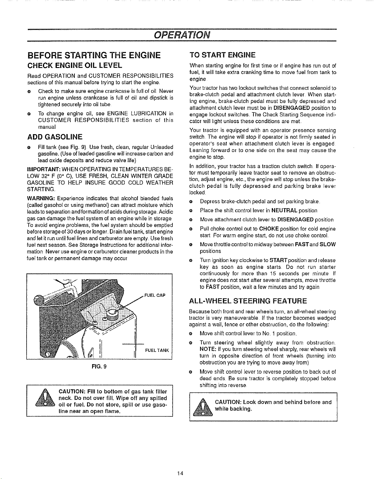
ADD GASOLINE
e Fill tank (see Fig 9) Use fresh, clean, regular Unleaded
gasoline. (Use of leaded gasoline will increase carbon and
lead oxide deposits and reduce valve life)
IMPORTANT: WHEN OPERATING IN TEMPERATURES BE-
LOW 32 ° F (0° C), USE FRESH, CLEAN WINTER GRADE
GASOLINE TO HELP INSURE GOOD COLD WEATHER
STARTING
WARNING: Experience indicates that alcohol blended fuels
(called gasohol or using methanol) can attract moisture which
leads to separation and formation of acids during storage. Acidic
gas can damage the rue! system of an engine while in storage
To avoid engine problems, the fuel system should be emptied
before storage of 30 days or longer Dr ain rue!tank, start engine
and let it run until fuel lines and carburetor are empty. Use fresh
fuel next season. See Storage Instructions for additional infor-
mation Never use engine or carburetor cleaner products in the
fuel tank or permanent damage may occur
TO START ENGINE
When starting engine for first time or if engine has run out of
fuel, itwill take extra cranking time to move fuel from tank to
engine
Your tractor has two lockout switches that connect solenoid to
brake-clutch pedal and attachment clutch lever When start-
ing engine, brake-clutch pedal must be fully depressed and
attachment clutch lever must be in DISENGAGED position to
engage lockout switches The Check Starting Sequence indi-
cator will light unless these conditions are met
Your tractor is equipped with an operator presence sensing
switch The engine will stop if operator is not firmly seated in
operator's seat when attachment clutch lever is engaged
Leaning forward or to one side on the seat may cause the
engine to stop
In addition, your tractor has a traction clutch switch If opera-
tor must temporarily leave tractor seat to remove an obstruc-
tion, adjust engine, etc, the engine will stop unless the brake-
clutch pedal is fully depressed and parking brake lever
locked
o
Depress brake-clutch pedal and set parking brake
O
Place the shift control lever in NEUTRAL position
O
Move attachment clutch lever to DISENGAGED position
O
Pull choke control out to CHOKE position for cold engine
start For warm engine start, de not use choke control
O
Move throttle control to midway between FAST and SLOW
positions
O
Turn ignitionkey clockwise to START position and lelease
key as soon as engine starts Do not ran starter
continuously for more than 15 seconds per minute If
engine does not start after several attempts, move throttle
to FAST position, wait a few minutes and try again
_ AUTION: Fill to bottom of gas tank filler ]
neck. Do not over fill Wipe off any spilled
oil or fuel Do not store, spill or use gaso-
line near an open flame.
ALL-WHEEL STEERING FEATURE
Because both front and rear wheels turn, an all-wheel steering
tractor is very maneuverable if the tractor becomes wedged
against a wall, fence or other obstruction, do the following:
e Moveshift controllevertoNo. 1position
O
Turn steering wheel slightly away from obstruction.
NOTE: If you turn steering wheel sharply, rear wheels will
turn in opposite direction of front wheels (turning into
obstruction you are trying to move away from)
e Move shift control lever to reverse position to back out of
dead ends Be sure tlactor is completely stopped before
I
shifting into reverse
_ AUTION: Look down and behind before and
I
wh le backing..
14
OPERATION
MOWING TiPS
e Do not use tire chains when mower housing isattached to
unit
e Run the engine at FAST speed position.
Control forward ground speed with shift control lever in
accordance with type and quantity of grass being
mowed. The more grass to be cut, a slower forward
ground speed should be used When cutting light grass,
forward ground speed can be increased By observing
cutting action of your mower, you can determine the
forward ground speed
Your mower may tend to leave unmowed strips when long
and tender grass is being mowed Tender grass has a high
internal moisture content and is easily depressed by lawn
tractor wheels, and may not always spring back in time to
be cut To overcome this condition, we advise mowing lawn
in a counterclockwise direction, overlapping previous cut,
which allows lifting action of rotating blades to lift grass into
cutting path
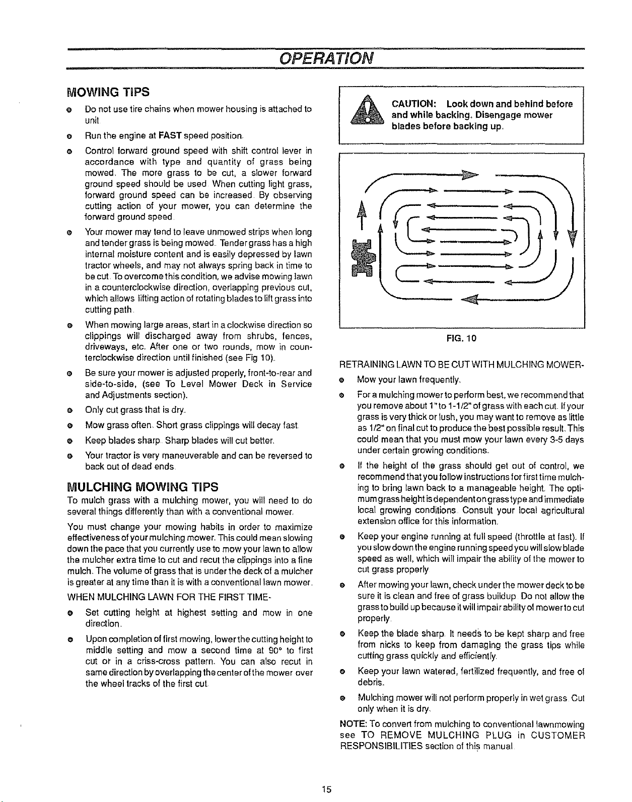
When mowing large areas, start in a clockwise direction so
clippings will discharged away from shrubs, fences,
driveways, etc. After one or two rounds, mow in coun-
terclockwise direction until finished (see Fig 10).
e Be sure your mower is adjusted properly,front-to-rear and
side-to-side, (see To Level Mower Deck in Service
and Adjustments section).
e Only cut grassthat is dry.
e Mow grass often. Short grass clippings will decay fast
e Keep blades sharp Sharp blades will cut better,
e Your tractor is very maneuverable and can be reversed to
back out of dead ends
MULCHING MOWING TiPS
To mulch grass with a mulching mower, you will need to do
several things differently than with a conventional mower.
You must change your mowing habits in order to maximize
effectiveness of your mulching mower. This could mean slowing
down the pace that you currently use to mow your lawn to allow
the mulchar extra time to cut and recur the clippings into a fine
mulch. The volume of grass that is under the deck of a mulcher
is greater at any time than it is with a conventional lawn mower
WHEN MULCHING LAWN FOR THE FIRST TIME-
• Set cutting height at highest setting and mow in one
direction.
@
Upon completion offirst mowing, lower the cutting height to
middle setting and mow a second time at 90° to first
cut or in a criss-eross pattern. You can also recut in
same direction by overlapping the center of the mower over
the wheel tracks of the first cut
CAUTION: Look down and behindbefore
and while backing,, Disengage mower
blades before backing up.
FIG. 10
RETRAINING LAWN TO BE CUT WITH MULCHING MOWER-
e Mow your lawn frequently,
@
For a mulching mower to perform best, we recom mend that
you remove about 1"to 1-1/2" of grass with each cut If your
grass is very thick or lush, you may want to remove as little
as 1/2" on final cut to produce the best possible result. This
could mean that you must mow your lawn every 3-5 days
under certain growing conditions.
@
If the height of the grass should get out of control, we
recommend that you follow instructions for first time mulch-
ing to bring lawn back to a manageable height The optF
mum grass height isdependenton grass type and immediate
local growing conditions Consult your local agricultural
extension office for this information
Keep your engine running at full speed (throttle at fast). If
you slow down the engine running speed you will slow blade
speed as well, which will impair the ability of the mower to
cut grass properly
After mowing your lawn, check under the mower deck to be
sure it is clean and free of grass buildup Do not allow the
grass to build up because it will impair ability of mower to cut
properly
e Keep the blade sharp It needs to be kept sharp and free
from nicks to keep from damaging the grass tips while
cutting grass quickly and efficiently
e Keepyour lawnwatered,fertilized frequently,and free of
debris.
• Mulching mower will not perform properly in wet grass Cut
only when it is dry
NOTE: To convert from mulching to conventional lawnmowing
see TO REMOVE MULCHING PLUG in CUSTOMER
RESPONSIBILITIES section of this manual
I
15
CUSTOMER RESPONSIBILITIES
GENERAL RECOMMENDATIONS
The warranty on this tractor does not cover itemsthat have been
subjected to operator abuse or negligence, To receive fuUvalue
from warranty, operator must maintain lawn tractor as instructed
in this manual
Some adjustments will need to be made periodically to properly
maintain your unit
All adjustments in the SERVICE AND ADJUSTMENTS section
of this manual should be checked at least once each season
Once a year you should replace spark plug, clean or
replace air filter, and check blades and belts for wear A
new spark plug and clean air filter assure proper air-fuel
mixture and help your engine run better and last longer
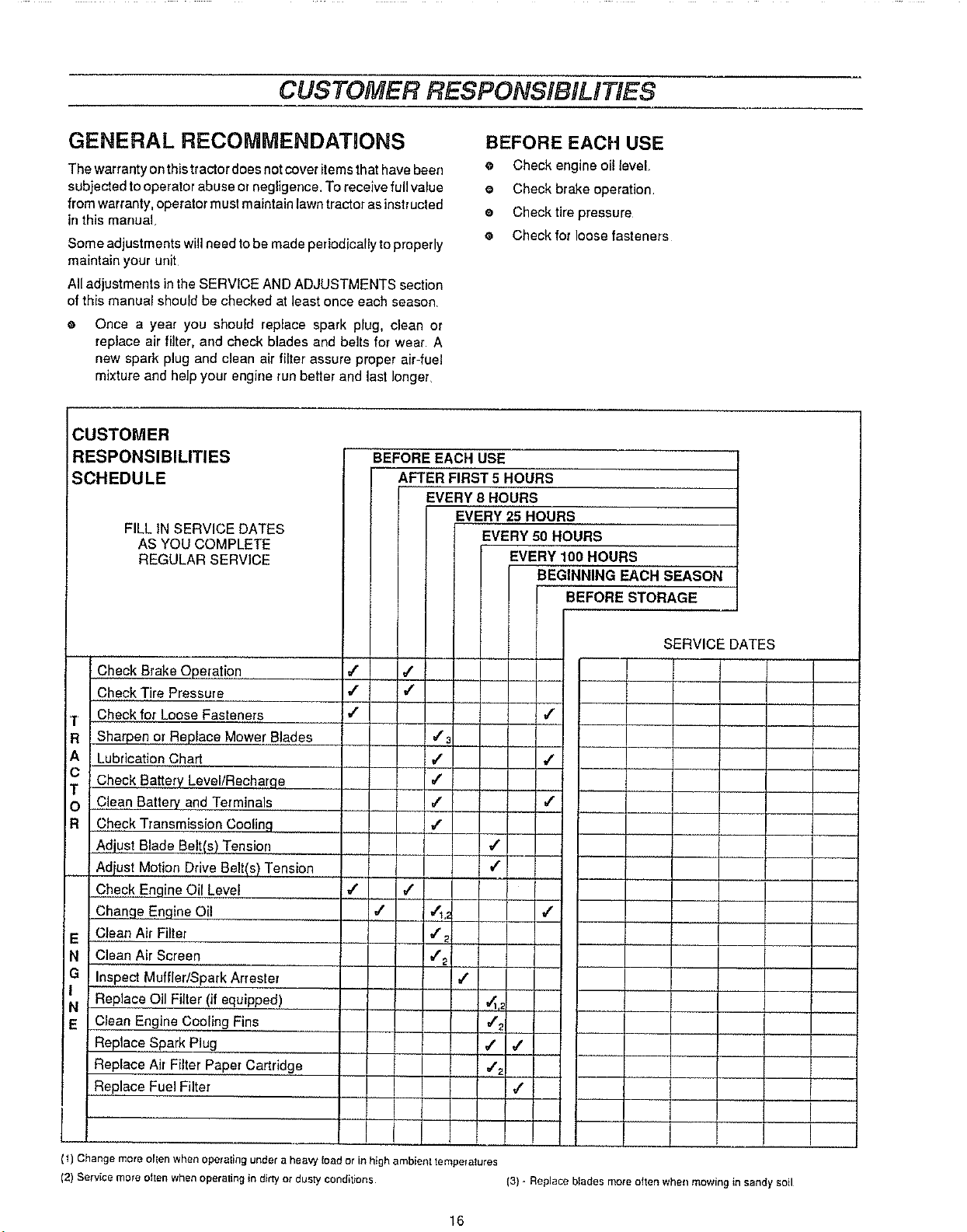
CUSTOMER
RESPONSIBILITIES
SCHEDULE
FILL IN SERVICE DATES
AS YOU COMPLETE
REGULAR SERVICE
BEFORE EACH USE
AFTER FIRST 5 HOURS
EVERY 8 HOURS
BEFORE EACH USE
e Check engine oillevel.
e Check brake operation.
e Checktire pressure
e Check for loose fasteners
EVERY 25 HOURS
EVERY 50 HOURS
EVERY 100 HOURS
BEGINNING EACH SEASON
BEFORE STORAGE
Check Brake Operation
Check Tire Pressure
Check for Loose Fasteners
Sharpen or Replace Mower Blades
Lubrication Chart
Check Battery Level/Recharqe
Clean Battery and Terminals
Check Transmission Coolinq
Adjust Blade Belt(s) Tension
Adiust Motion Drive Belt(s) Tension
Check Engine Oil Level
Change Engine Oil
Clean Air Filter
Clean Air Screen
Inspect Muffler/Spark Arrester
Replace Oil Filter (if equipped)
Clean Engine Cooling Fins
Replace Spark Plug
Replace Air Filter Paper Cartridge
Replace Fuel Filter
(1) Change more ollen when operaling under a heavy load or in high ambienl tempeIalures
(2) Service more ohen when operating in dirty of dusly conditions
SERVICE DATES
I
i
(3) - Replace blades more often when mowing in sandy soil
I
I
16
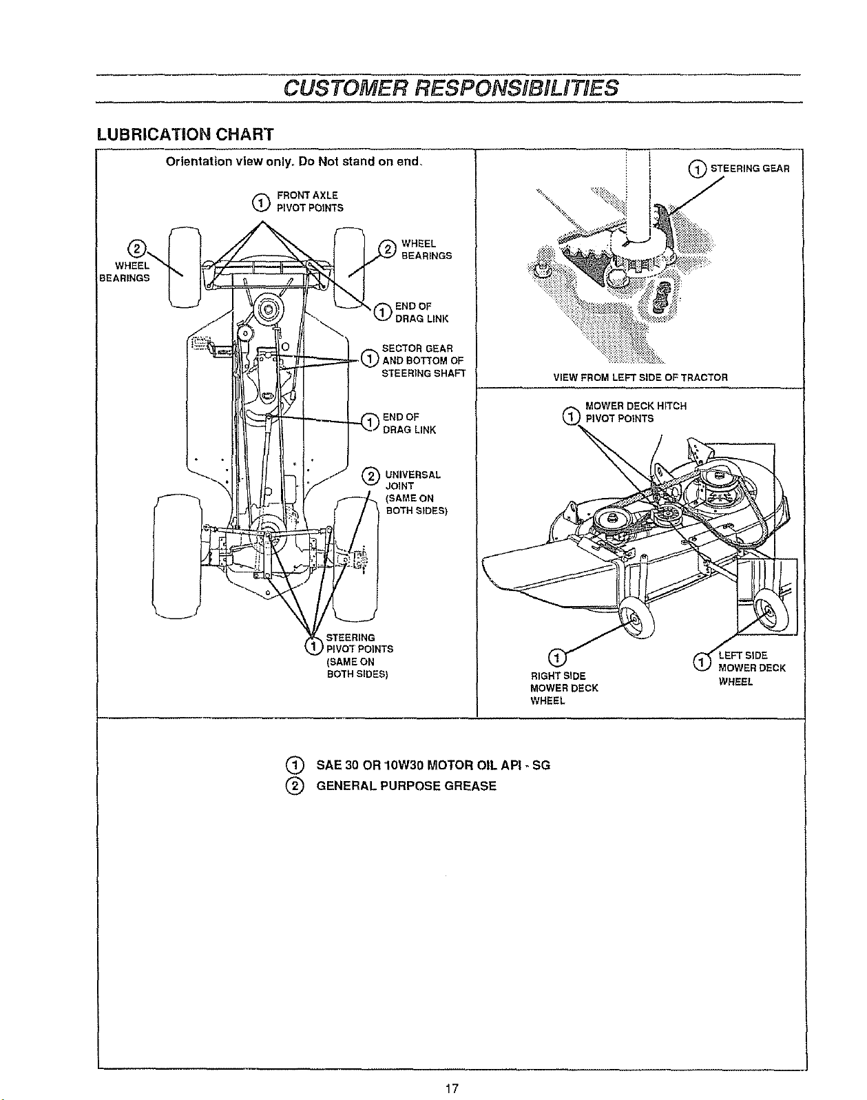
LUBRiCATiON CHART
CUSTOMER RESPONSIBILITIES
WHEEL
BEARINGS
Orientation view only,, Do Not stand on end.
FRONT AXLE
PIVOT POINTS
WHEEL
BEARINGS
END OF
(_ DRAG LINK
SECTOR GEAR
) AND BOTTOM OF
STEERING SHAFT
END OF
(_ UNIVERSAL
JOINT
(SAME ON
BOTH StDES)
(_STEERING GEAR
VIEW FROM LEFT SIDE OF TRACTOR
STEERING
) PIVOTPOINTS
(SAME ON
BOTHSIDES)
RIGHT SIDE
MOWER DECK
WHEEL
Q SAE 30 OR 10W30 MOTOR OIL API _ SG
(_) GENERAL PURPOSE GREASE
(_MEoFT SIDE
WER DECK
WHEEL
17
TRACTOR
CUSTOMER RESPONSIBiLITiES
Always observe safety rules when performing any
maintenance.
BRAKE OPERATION
Your tractor is equipped with an edjustable disc brake To check
brake operation do the following:
e Stop tractor on a level surface and place shift control lever
in NEUTRAL position.
o
Depress brake..clutch pedal enough to latch parking brake
in 2nd notch,
o
Try to push tractor. Ifyou are unable to push tractor, brake
is too tight and should be loosened (see TO ADJUST
TRACTOR BRAKE in SERVICE AND ADJUSTMENTS
section of this manual
o
Depress brake-clutch pedal enough to latch parking brake
in 4th notch
o
Try to push tractor. If you are able to push tractor, brake is
too loose and should be tightened (see TO ADJUST
TRACTOR BRAKE in SERVICE AND ADJUSTMENTS
section of this manual.
During tractor operation, check for stopping distance If tractor
requires more than six (6) feet stopping distance at high speed
in highest gear, the brake must be adjusted (see to ADJUST
TRACTOR BRAKE in SERVICE AND ADJUSTMENTS section
of this manual),
TIRES
s Maintain proper air pressure in all tires (See "PRODUCT
SPECIFICATIONS" on page 3 of this manual)
Keep tires free of gasoline, oil, or irrsectcontrol chemicals
which can harm rubber
e Avoid stumps, stones, deep ruts, sharp objects and other
hazards that may cause tire damage.
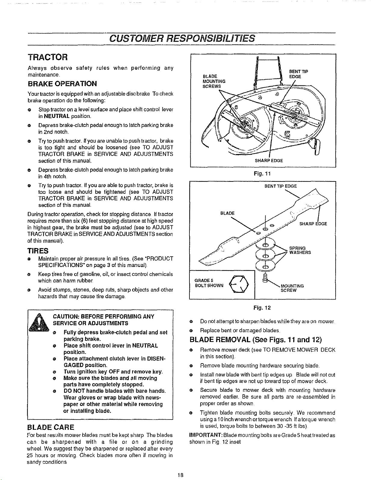
BLADE
MOUNTING
SCREWS
SHARP EDGE
Fig. 11
BENT TiP EDGE
BLADE
BOLT SHOWN MOUNTING
GRADE S Q
BENT TIP
SCREW
EDGE
SPRING
WASHERS
SHARP E
CAUTION: BEFOREPERFORMING ANY
SERVICEOR ADJUSTMENTS
• Fullydepress brake-clutch pedal andset
parking brake.
e Placeshift control lever inNEUTRAL
position.
• Placeattachment clutch leverIn DISEN-
GAGED position,
e Turn Ignition key OFF andremove key.
e Make sure the blades and all moving
parts have completely stopped,
e DO NOT handle blades with bare hands.
Wear gloves or wrap blade with news-
paper or other material while removing
or installing blade,
BLADE CARE
For best results mower blades must be kept sharp The blades
can be sharpened with a file Dr on a grinding
wheel We suggest they be sharpened or replaced after every
25 hours or mowing Check blades more often if mowing in
sandy conditions
Fig. 12
e Do rrot attempt to sharpen blades whilethey are on mower
e Replace bent or damaged blades.
BLADE REMOVAL (See Figs. 11 and 12)
e Remove mower deck (see TO REMOVE MOWER DECK
in this section)
e Remove blade mounting hardware securing blade.
e Install new blade with bent tip edges up Blade will not cut
if bent tip edges are not up toward top of mower deck.
e Secure blade to mower deck with mounting hardware
removed earlier. Be sure all parts are re-assembled in
proper order as shown
e Tighten blade mounting bolts securely We recommend
using a 10inchwrench or torque wrench Ifatorque wrench
is used, torque bolts to between 30 -35 ft Ibs)
IMPORTANT: Blade mounting bolts are Grade 5 heat treated as
shown in Fig 12 inset
18
CUSTOMER RESPONSIBILITIES
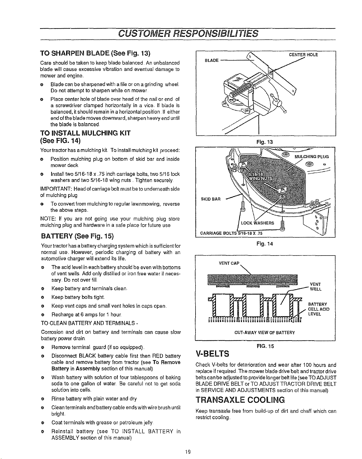
TO SHARPEN BLADE (See Fig. 13)
Care should be taken to keep blade balanced An unbalanced
blade wil! cause excessive vibration and eventual damage to
mower and engine.
e Blade can be sharpened with a file or on a grinding wheel
Do not attempt to sharpen while on mower
o Place center hole of blade over head of the nail or end of
a screwdriver clamped horizontally in a vice If blade is
balanced, it should remain in a horizontal position If either
end ofthe blade moves downward, sharpen heavy end until
the blade is balanced
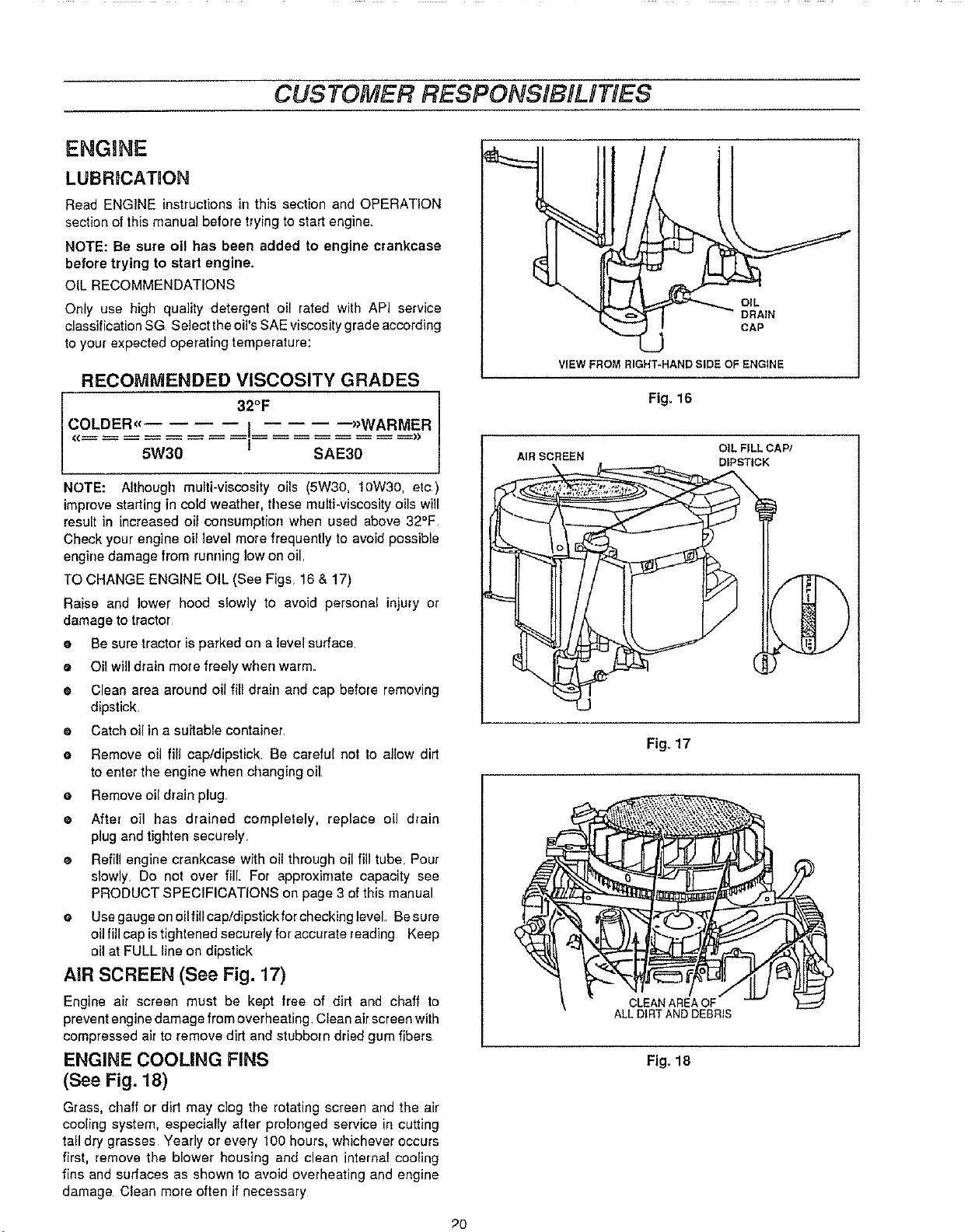
TO iNSTALL MULCHING KIT
(See FiG. 14)
Your tractor has a mulching kit To install mulching kit proceed:
e Position mulching plug on bottom of skid bar and inside
mower deck
e Install two 5/16-18 x 75 inch carriage bolts, two 5/16 lock
washers and two 5;/16-18 wing nuts Tighten securely
IMPORTANT: Head of carriage bolt must be tounderneath side
of mulching plug
e To convert from mulchingto regular lawnmowing, reverse
the above steps_
NOTE: If you are not going use your mulching plug store
mulching plug and hardware in a safe place for future use
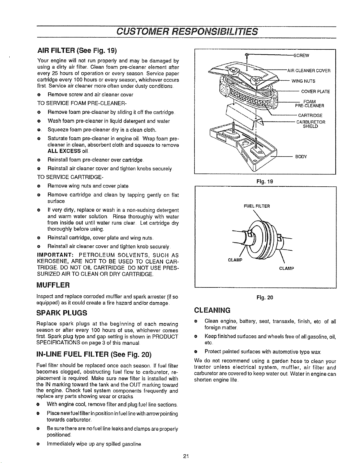
BATTERY (See Fig. 15)
Your tractor has a battery charging system which is sufficient for
normal use However, periodic charging of battery with an
automotive charger will extend its life
a The acid level in each battery should be even with bottoms
of vent wells Add only distilled or iron free water ifneces-
sary. Do not over fill
e Keep battery and terminals clean
e Keep battery bolts tight.
e Keep vent caps and small vent holes in caps open
e Recharge at 6 amps for I hour
TO CLEAN BA'I3ERY AND TERMINALS -
Corrosion and dirt on battery and terminals can cause slow
battery power drain
e Remove terminal guard (if so equipped)
e Disconnect BLACK battery cable first then RED battery
cable and remove battery from tractor (see To Remove
Battery in Assembly section of this manual)
e Wash battery with solution of four tablespoons of baking
soda to one gallon of water Be careful not to get soda
solution into cells
• Rinse battery with plain water and dry
e Clean terminals and battery cable ends with wire brush until
bright
® Coat terminals with grease or petroleum jelly
e Reinstall battery (see TO INSTALL BATTERY in
ASSEMBLY section of this manual)
CENTER HOLE
BLADE
Fig. 13
MULCHING PLUG
SKID eAR
CARRIAGE BOLTS 5/16-18 X 75
Fig, 14
VENT
/ WELL
CELLACID
BATTERY
LEVEL
CUT-AWAY VIEW OF BATTERY
FIG. 15
V-BELTS
Check V-belts for deterioration and wear after 100 hours and
replace if required The mower blade drive belt and tractor drive
belts can be adjusted to provide longer belt lite (see TO ADJUST
BLADE DRIVE BELT or TO ADJUST TRACTOR DRIVE BELT
in SERVICE AND ADJUSTMENTS section of this manual)
TRANSAXLE COOLING
Keep transaxle free from build-up of dirt and chaff which can
restrict cooling
19
CUSTOMER RESPONSIBILITIES
ENGINE
LUI3RDCATION
Read ENGINE instructions in this section and OPERATION
section of this manual before trying to start engine.
NOTE: Be sure oil has been added to engine crankcase
before trying to start engine.
OIL RECOMMENDATIONS
Only use high quality detergent oi! rated with API service
classification SG Select the oil's SAE viscosity grade according
to your expected operating temperature:
RECOMMENDED VISCOSITY GRADES
32o :, AR%R
NOTE: Although multi-viscosity oils (5W30, 10W30, etc)
improve starting in cold weather, these multi-viscosity oils will
result in increased oil consumption when used above 32°F
Check your engine oil level more frequently to avoid possible
engine damage from running low on oil.
TO CHANGE ENGINE OIL (See Figs 16 & 17)
Raise and lower hood slowly to avoid personal injury or
damage to tractor
e Be sure tractor is parked on a level surface,
• Oil will drain more freely when warm.
e Clean area around oil fill drain and cap before removing
dipstick
e Catch oilin a suitable container
e Remove oil fill cap/dipstick. Be careful not to allow dirt
to enter the engine when changing oil
• Remove oil drain plug.
e After oil has drained completely, replace oil drain
plug and tighten securely.
• Refill engine crankcase with oil through oil fill tube. Pour
slowly. Do not over fill. For approximate capacity see
PRODUCT SPECIFICATIONS on page 3 of this manual
e Use gauge on oilfill cap/dipstick for checking level Besure
oUfill cap istightened securely for accurate reading Keep
oil at FULL line on dipstick
AIR SCREEN (See Fig. 17)
Engine air screen must be kept free of dirt and chaff to
prevent engine damage from overheating Clean air screen with
compressed air to remove dirt and stubborn dried gum fibers
ENGINE COOLING FINS
(See Fig. 18)
Grass, chaff or dirt may clog the rotating screen and the air
cooling system, especially after prolonged service in cutting
tall dry grasses Yearly or every 100 hours, whichever occurs
first, remove the blower housing and clean internal cooling
fins and surfaces as shown to avoid overheating and engine
damage Clean more often if necessary
J
VIEW FROM RIGHT-HAND SIDE OF ENGINE
Fig. 16
OIL FILL CAP/
AIR SCREEN DIPSTICK
Fig= 17
ALL DIRTAND DEBRIS
Fig, 18
70
CUSTOMER RESPONSiBiLITiES
AIR FILTER (See Fig. 19)
Your engine will not run properly and may be damaged by
using a dirty air filter, Clean foam pre-cleaner element after
every 25 hours of operation or every season Service paper
cartridge every 100 hours or every season, whichever occurs
first Service air cleaner more often under dusty conditions
e Remove screw and air cleaner cover
TO SERVICE FOAM PRE-CLEANER-
e Remove foam pre-cleaner by sliding it off the cartridge
e Wash foam pre-cleaner in liquid detergent and water
• Squeeze foam pre-cleaner dryina clean cloth_
e Saturate foam pre-cleaner in engine oil. Wrap foam pre-
cleaner in clean, absorbent cloth and squeeze to remove
ALL EXCESS oil
e Reinstall foam pre-cleaner over cartridge
® Reinstall air cleaner cover and tighten knobs securely
TO SERVICE CARTRIDGE-
® Remove wing nuts and cover plate
® Remove cartridge and clean by tapping gently on flat
surface
• If very dirty, replace or wash in a non-sudsing detergent
and warm water solution. Rinse thoroughly with water
from inside out until water runs clear Let cartridge dry
thoroughly before using.
® Reinstall cartridge, cover plate and wing nuts.
e Reinstall air cleaner cover and tighten knob securely
IMPORTANT: PETROLEUM SOLVENTS, SUCH AS
KEROSENE, ARE NOT TO BE USED TO CLEAN CAR-
TRIDGE. DO NOT OIL CARTRIDGE DO NOT USE PRES-
SURIZED AIR TO CLEAN OR DRY CARTRIDGE
CLAMP
AER CLEANER COVER
WING NUTS
_ COVER PLATE
,_ ; FOAM
'_E-CLEANER
'*'----- CARTRIDGE
.,_ CARBURETOR
Fig. 19
FUEL FILTER
CLAMP
SHIELD
BODY
MUFFLER
Inspect and replace corroded muffler and spark attester (if so
equipped) as it could create a fire hazard and/or damage
SPARK PLUGS
Replace spark plugs at the beginning of each mowing
season or after every 100 hours of use, whichever comes
first Spark plug type and gap setting is shown in PRODUCT
SPECIFICATIONS on page 3 of this manual
IN-LINE FUEL FILTER (See Fig. 20)
Fuel filter should be replaced once each season If fuel filter
becomes clogged, obstructing fuel flow to carburetor, re-
placement is required Make sure new filter is installed with
the IN marking toward the tank and the OUT marking toward
the engine, Check fuel system components frequently and
replace any parts showing wear or cracks
• With engine cool, remove filter and plug fuel line sections
e Place new fuelfilter inposition in fuel linewith arrow pointing
towards carburetor,
e Be sure there are no fuel line leaks and clamps are properly
positioned
e Immediately wipe up any spilled gasoline
Fig. 20
CLEANING
o
Clean engine, battery, seat, transaxle, finish, etc of all
foreign matter
@
Keep finished surfaces and wheels free of all gasoline, oil,
etc
e Protect painted surfaces with automotive type wax
We do not recommend using a garden hose to clean your
tractor unless electrical system, muffler, air filter and
carburetor are covered to keep water out Water in engine can
shorten engine life
21
SERVICE AND ADJUSTMENTS
CAUTION: BEFORE PERFORMING ANY SERVICE ORADJUSTMENTS
• Depress brake-clutchpedal and set parking brake°
e Place shift control lever in NEUTRAL position.
e Place attachment clutch lever in DISENGAGED posittom
e Turn Ignltlonkey OFF and remove key.
e Make sure the blades and all moving parts have completely stopped.
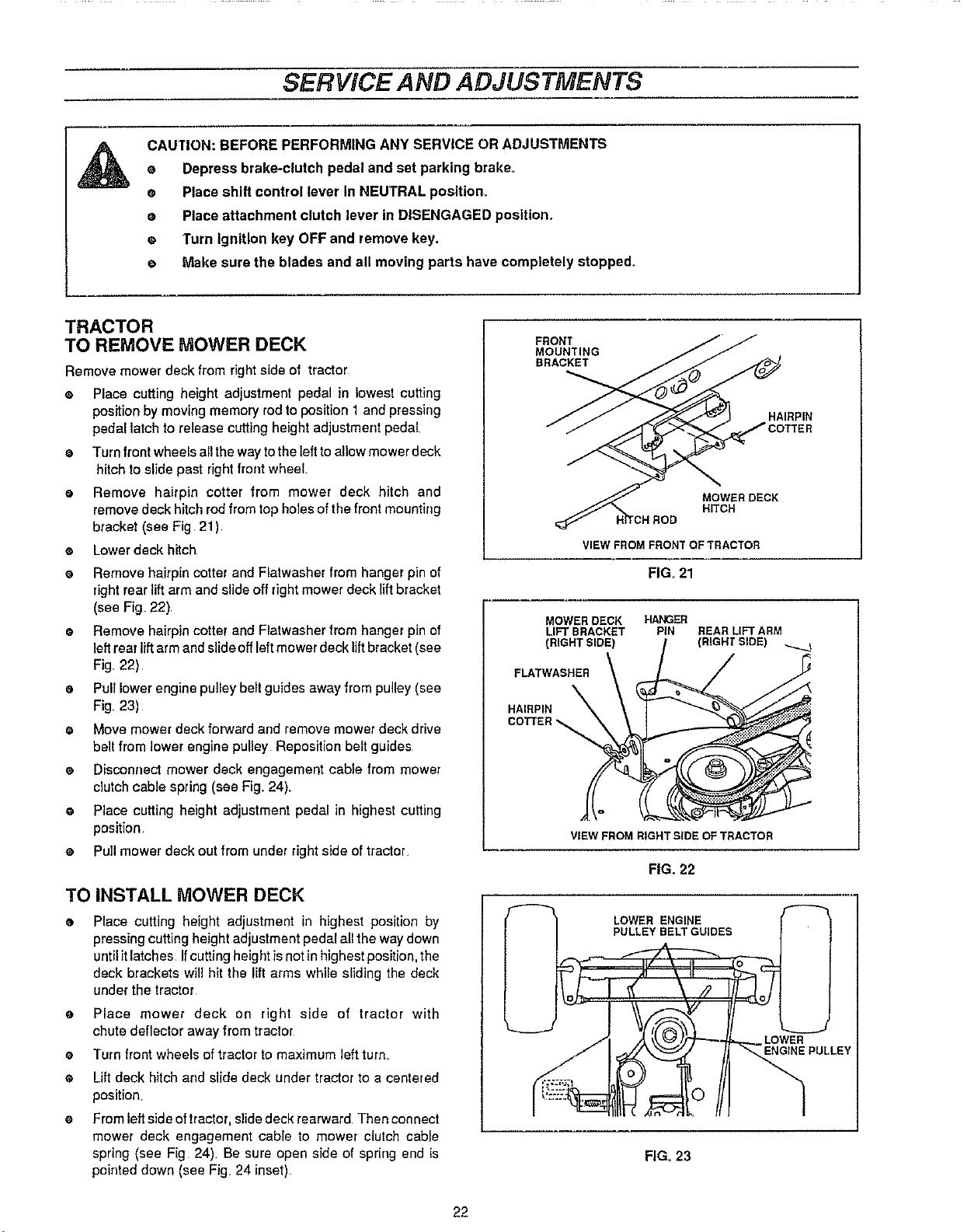
TRACTOR
TO REMOVE MOWER DECK
Remove mower deck from right side of tractor
e Place cutting height adjustment pedal in lowest cutting
position by moving memory rod to position 1 and pressing
pedal latch to release cutting height adjustment pedal_
• Turn front wheels all the way to the leftto allow mower deck
hitch to slide past dght front wheel
• Remove hairpin cotter from mower deck hitch and
remove deck hitchrod from top holes of the front mounting
bracket (see Fig 21)
e Lower deck hitch
e Remove hairpin cotter and Flatwasher from hanger pin of
right rear lift arm and slide off right mower deck lift bracket
(see Fig. 22)
• Remove hairpin cotter and Flatwasher from hanger pin of
left rear lift arm and slide off left mower deck lift bracket (see
Fig. 22)
e Pull lower engine pulley belt guides away from pulley (see
Fig. 23)
• Move mower deck forward arrd remove mower deck drive
belt from lower engine pulley Reposition belt guides
e Disconnect mower deck engagement cable from mower
clutch cable spring (see Fig_24).
e Placecutting height adjustment pedal in highest cutting
position
• Puit mower deck out from under right side of tractor.
TO INSTALL MOWER DECK
o
Place cutting height adjustment in highest position by
pressing cutting height adjustment pedal all the way down
until it latches If cutting height is not in highest position, the
deck brackets will hit the lift arms while sliding the deck
under the tractor
o
Place mower deck on right side of tractor with
chute deflector away from tractor
o
Turn front wheels of tractor to maximum leftturn
o
Lift deck hitch and slidedeck under tractor to a centered
position,
o
From left side of tractor, slide deck rearward Then connect
mower deck engagement cable to mower clutch cable
spring (see Fig 24). Be sure open side of spring end is
poieted down (see Fig 24 inset)
FRONT
MOUNTING
BRACKET
VIEW FROM FRONT OFTRACTOR
FIG. 21
MOWER DECK HANGER
LIFT BRACKET PIN REAR LIFTARM
(RIGHTSIDE) (RIGHT SIDE)
FLATWASHER
HAIRPIN
COTTER
VIEW FROM RIGHTSIDE OF TRACTOR
FIG. 22
LOWER ENGINE
PULLEY BELT GUIDES
FIGo23
MOWER DECK
H_CH
LOWER
ENGINE PULLEY
HAIRPIN
22
 Loading...