

Craftsman 486.248531 User Manual

Owner's Manual
42' - 2 STAGE SNOW THROWER
TRACTOR ATTACHMENT
Model No. 486.248531
CAUTION:
Before using this product, read
this manual and follow all
Safety Rules and
Operating Instructions.
IMPORTANT - READ THIS FIRST!!!
For Missing Parts or Assembly Questions
Please Call 217-728-8388
Mon.-Fri. 7 am - 5 pm CST.
FAX 217-728-2032 or e-mail info@aari-fab.com
Missing parts will be sent UPS in 24 hours directly to your home.
Sears, Roebuck and Co., Hoffman Estates, IL 60179 U.S.A.
www.sears.com/craftsman
PRINTED IN U.S.A.
• Assembly
• Operation
• Maintenance
• Parts
FORM NO. 48935 (7/03)
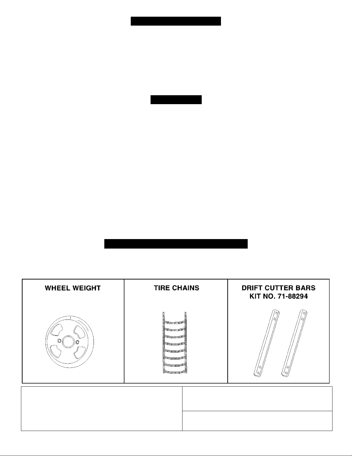
TABLE OF CONTENTS
ACCESSORIES..............................................................2
SAFETY RULES.............................................................3
FULL SIZE HARDWARE CHART
CARTON CONTENTS....................................................5
ASSEMBLY.....................................................................5
OPERATION.................................................................15
MAINTENANCE............................................................16
..................................
4
SERVICE AND ADJUSTMENTS..................................17
STORAGE
TROUBLESHOOTING..................................................18
REPAIR PARTS ILLUSTRATION
REPAIR PARTS LIST..............................................21,23
SLOPE GUIDE..............................................................27
PARTS ORDERING/SERVICE
....................................................................
...........................
..................
BACK COVER
20,22
18
WARRANTY
LIMITED ONE YEAR WARRANTY ON 42" 2-STAGE SNOW THROWER
For one year from the date of purchase, when this snow thrower is maintained and lubricated according to the operating
and maintenance instructions in the owner's manual, Sears will repair any defect in materia! or workmanship free of charge.
If this snow thrower is used for commercial or rental purposes, this warranty applies for only 90 days from the date of
purchase.
This warranty does not cover repairs necessary because of operator negligence or abuse, including the failure to maintain
the equipment according to instructions contained in the owner's manual.
WARRANTY SERVICE IS AVAILABLE BY CONTACTING THE NEAREST SEARS SERVICE CENTER/DEPARTMENT
IN THE UNITED STATES.
This warranty applies only while this product is in the United States.
This warranty gives you specific legal rights, and you may also have other rights which vary from state to state.
Sears, Roebuck and Co. D/817 WA. Hoffman Estates, Chicago, IL 60179
ACCESSORIES AND ATTACHMENTS
These accessories were available when the unit was purchased. They are also available at most Sears retail outlets
and service centers. Most Sears stores can order repair parts for you when you provide the model numbers of your
tractor and snow thrower.
The mode! number and serial numbers will be found on a
decal attached to the snow thrower.
You should record both the serial number and the date of
purchase and keep in a safe place for future reference.
MODEL NUMBER: 486.24853
SERIAL NUMBER:
DATE OF PURCHASE:

SAFETY
Any power equipment can cause injury if operated improperly or if the user does not understand how to operate
the equipment. Exercise caution at all times, when using power equipment.
Read this owner's manual carefully and know how
to operate your snow thrower and how to stop the
unit and disengage the controls quickly.
Never allow children to operate the equipment.
Never allow adults to operate the equipment
without proper instruction.
Keep the area of operation clear of ail persons,
especially small children, and pets.
Thoroughly inspect the area where the equipment
is to be used and remove ail door mats, sleds,
boards, wires and other foreign objects.
Disengage all clutches and shift into neutral before
starting engine.
Do not operate equipment without wearing ad
equate winter outer garments.
Wear substantial footwear which wiii protect feet
and improve footing on slippery surfaces.
Check fuel before starting the engine. Do not
remove the fuel cap or fill the fuel tank while the
engine is running or hot. Do not fill the fuel tank
indoors. Gasoline is an extremely flammable fuel.
Make sure the snow thrower height is adjusted to
ciear the type surface it will be used on.
Do not use the snow thrower without the rear
weight attached to the tractor.
Never make any adjustments while the engine is
running.
Always wear safety glasses or eye shield during
operation or while performing and adjustment or
repair.
Do not place hand or feet near rotating parts. Keep
clear of the discharge opening at aii times.
Use extreme caution when operating on or crossing
gravei surfaces.
Do not carry passengers.
After striking a foreign object, stop the engine,
remove the wire from the spark plug and then
thoroughly inspect the snow thrower for damage.
Repair any damage before restarting and operating
the snow thrower.
If the snow thrower starts to vibrate abnormally,
stop the engine immediately and check for the
cause. Vibration is generaliy a warning of trouble.
Stop the engine whenever you leave the operating
position, before unclogging the snow thrower or
making any adjustments or inspections.
Take all possible precautions when leaving the unit
unattended. Disengage the attachment clutch lever
or switch, lower the snow thrower, shift into neutral,
set the parking brake, stop the engine and remove
the key.
When cieaning, repairing or inspecting, make
certain all moving parts have stopped. Disconnect
the spark plug wire and keep it away from the plug
to prevent accidental starting.
Do not run engine indoors except when transport
ing the snow thrower in or out of the building. Open
the outside doors. Exhaust fumes are dangerous.
Do not clear snow across the face of slopes.
Exercise extreme caution when changing direction
on slopes. Do not attempt to clear steep slopes.
Refer to the slope guide on page 27 of this manual.
Never operate the snow thrower without guards,
plates or other safety protection devices in place.
Never operate the snow thrower near glass enclo
sures, automobiles, window wells, drop offs etc.
without proper adjustment of the snow thrower
discharge angle.
Never direct discharge at bystanders or allow
anyone in front of the snow thrower.
Never run the snow thrower into material at high
speeds.
Do not overload the machine capacity by attempt
ing to clear snow at too fast a rate.
Never operate the machine at high transport speed
on slippery surfaces. Look behind and use care
when backing.
Watch for traffic and stay aiert when crossing or
operating near roadways.
Disengage power to the snow thrower when trans
porting or when not in use.
Use only attachments and accessories approved by
the manufacturer of the snow thrower (such as
wheel weights, counter weights, cabs etc.)
Never operate the snow thrower without good
visibility or light.
Look for this symbol to point out important safety precautions. It mean-Attention!!
A
Become alert!! Your safety is involved.
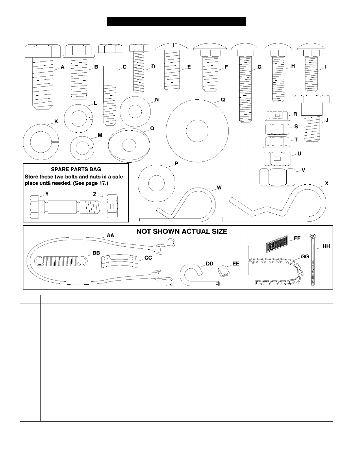
HARDWARE PACKAGE CONTENTS
SHOWN ACTUAL SIZE
REF. QTY. DESCRIPTION REF. QTY. DESCRIPTION
A 1
B 4
c
D
E 2
G
H 2
1
J
K 1 Lock Washer, 1/2”
L
M 12
N
0
P 2 Washer, 5/16"
Q
Hex Bolt, 1/2" X 1-1/4”
Hex Bolt, 3/8” X 1" (Thread Forming)
2
Hex Bolt, 5/16” X 1-3/4”
Hex Bolt, 1/4” X 1"
6
Slotted Truss Head Bolt, 3/8” x 1"
4
Carriage Bolt, 3/8” x 1”
2
Carriage Bolt, 5/16” x 1-3/4"
Carriage Bolt, 5/16” x 1-1/4”
6 Carriage Bolt, 5/16” x 1"
4
Shoulder Bolt, 3/8” x 5/8”
Lock Washer, 3/8” CC 3 Chute Keeper
10
Lock Washer, 5/16”
Washer, 1 /4" EE 1
6
2
Bowed Washer
2 Washer, 1 /2" HH 2 Nylon Tie
R
S
T 1
u
V 1
W 1 Hairpin Cotter, 3/32"
X
Y 2
6
12
11
3
z 2
AA 1
BB 1 Spring
DD 2 Lock Pin
FF 2 Tail Reflector
GG
1 Chain, Tensioning
Flanged Lock Nut, 1/4"
Hex Nut, 5/16”
Whiziock Nut, 5/16”
Hex Lock Nut, 3/8"
Hex Nut, 1/2”
Hairpin Cotter, 1/8"
Shear Bolt (spare parts)
Hex Lock Nut, 5/16" (spare parts)
Tarp Strap
Plastic Cap
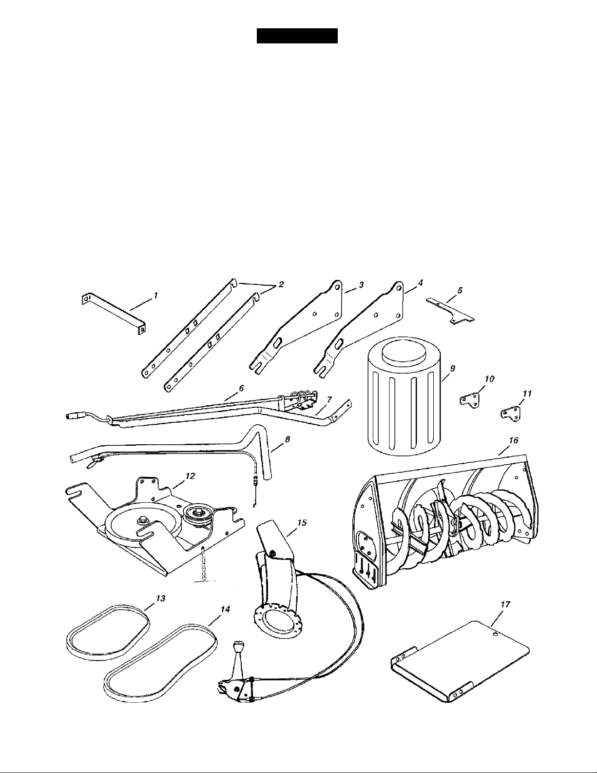
CARTON CONTENTS
ASSEMBLY
1.
Cross Brace (Weight Tray)
2.
Side Brace (Weight Tray)
3. Right Hand Side Plate (Stamped "R")
4.
Left Hand Side Plate (Stamped "L")
Anti-rotation Bracket
5.
6. Chute Crank Rod Assembly
7
Support Tube, Crank Rod 15
8. Lift Handle Tube and Cable
9.
Plastic Keg
10
Left Hand Hanger Bracket {Stamped "L")
11
Right Hand Hanger Bracket (Stamped "R”)
12
Ciutch Idier Assembly
V Beit, Drive
13
14
V Beit, Auger (Attached to Housing Assembiy)
Chute and Control Cable Assembly
16
Housing Assembly
17
Weight Tray
Hardware Package (Stored inside Plastic Keg)
TOOLS REQUIRED FOR ASSEMBLY
INSTALLING SIDE PLATES ON TRACTOR
(2)
(2)
(2)
(2)
(1)
ADDITIONAL ITEMS REQUIRED
7/16" Wrenches
1/2" Wrenches
9/16" Wrenches
3/4" Wrenches
Knife
General Purpose Grease
REMOVAL OF PARTS FROM CARTON
• Remove all parts and hardware packages from the
carton. Lay out parts and hardware and identify using
the illustrations on pages 4 and 5.
NOTE: Not all of the supplied parts and hardware
will be needed for your particular tractor. Unneeded
items may be discarded after you have completed
assembly.
CAUTION: Before starting to assemble
the snow thrower, remove the spark plug
wire{s), set the parking brake and
A
remove the key from the tractor ignition.
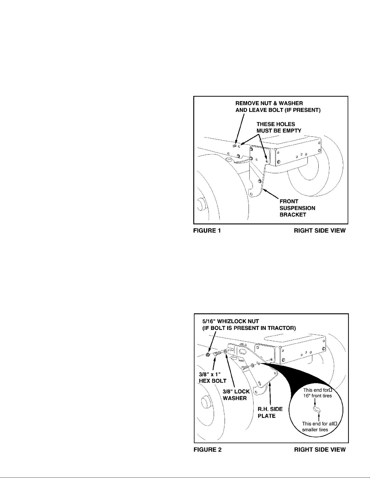
TRACTORS WITH FRAME MOUNTED FRONT
SUSPENSION BRACKETS {See figure 1.)
* Remove any bolts that are present in the two holes
shown as empty in figure 1.
• If there is a bolt in the third hole shown in figure 1,
remove the nut and washer but leave the bolt in place.
TRACTOR PREPARATION
Before performing these instructions, refer to the Service
and Adjustments section of your tractor owner's manual
for specific safety instructions.
• Allow engine, muffler and exhaust deflector to cool
before beginning.
• Remove any front or rear attachment which is
mounted to your tractor.
• Remove the mower deck. Refer to your tractor
owner's manual for removal instructions. Mark all
loose parts and save for reassembly.
• Remove the tractor hood and grill assembly. Refer to
your tractor owner's manual for removal instructions.
ITEMS REMOVED FROM TRACTOR
Store all parts that you remove from the tractor and do
not re-use while assembling the snow thrower.
• Assemble the R.H. Side Piate (marked "R") to the
two now empty holes in the side of the tractor frame.
Use two 3/8" X 1" hex bolts and 3/8" lock washers as
shown in figure 2. Repeat for the L.H. side.
• If you removed a nut and washer from the bolt in
figure 1, assemble a whizlock nut onto the bolt.
NOTE: If you remove the side piates, be sure to
reassemble ail bolts to tractor frame .
Right hand (R.H.) and left hand (L.H.) side of the tractor
are determined from the operators position while seated
on the tractor.
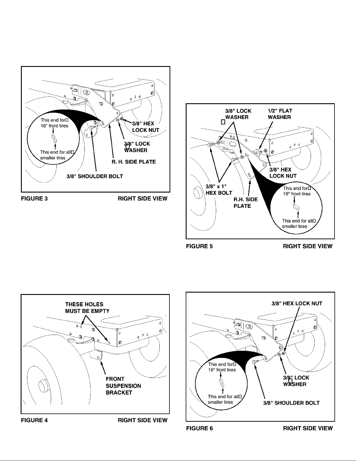
• Assemble a shoulder bolt, a 3/8" lock washer and a
3/8" hex lock nut to the bottom hole in each side
plate. See figure 3.
• Proceed to page 8.
• Attach the R.H. Side Plate (marked "R") to the right
side of the tractor frame as shown in figure 5. For the
front hole use a 3/8" x 1" hex bolt, a 3/8" lock washer,
and a 1/2" flat washer. Use the flat washer as a shim
between the frame and the side plate. For the rear
hole use a 3/8" x 1" hex bolt, and a 3/8" lock washer.
Repeat for the L.H. side.
NOTE: If the bolt inserts freely into the front hole, the
3/8" lock washer along with a 3/8" hex lock nut must
be assembled onto the bolt from inside the tractor
frame.
TRACTORS WITH AXLE MOUNTED FRONT
SUSPENSION BRACKETS
•
• Remove any bolts present in the holes shown in
figure 4 on both sides of the tractor frame.
• Assemble a shoulder bolt, a 3/8" lock washer and a
3/8" hex lock nut to the bottom hole in each side
plate. See figure 6.
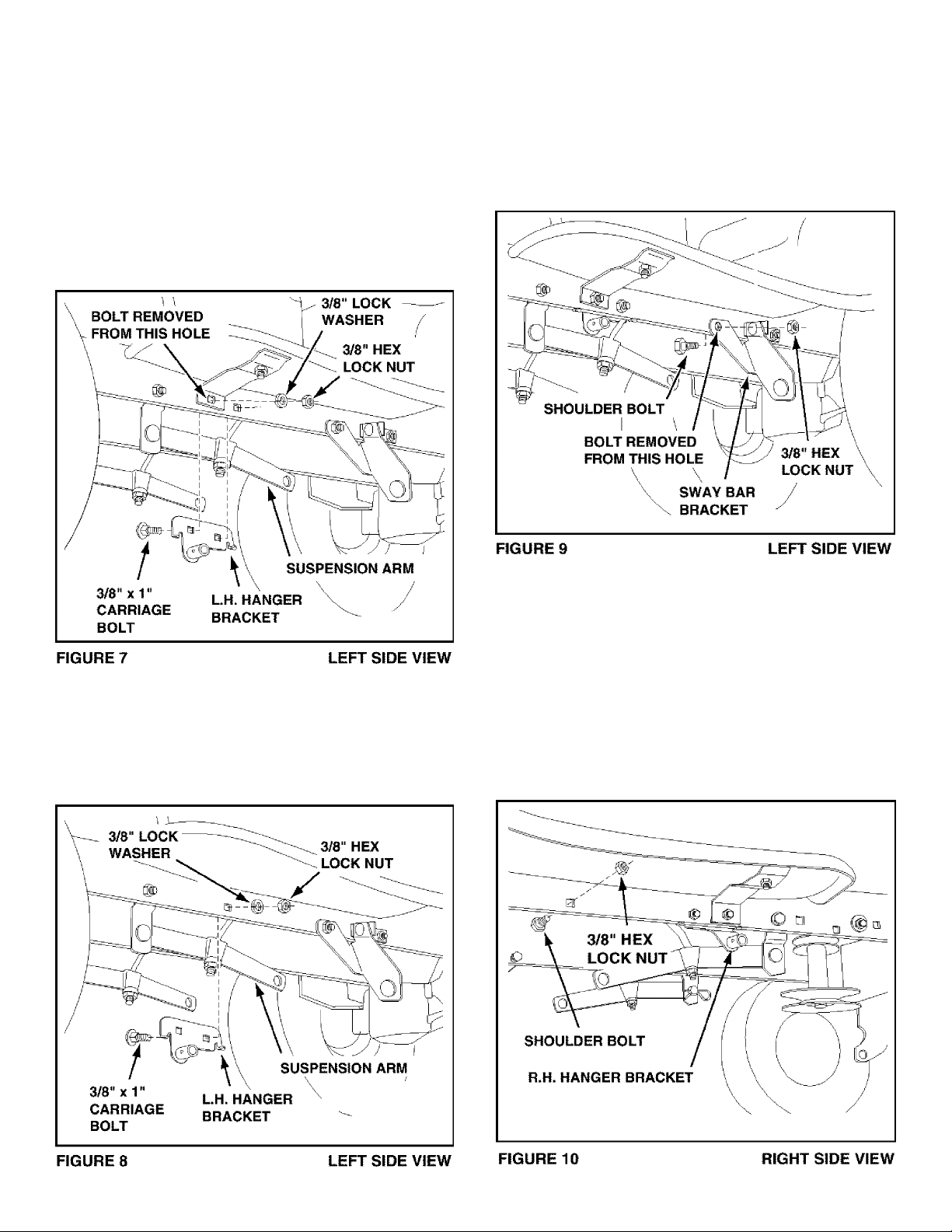
INSTALLING HANGER BRACKETS
For better clearance, lower the tractor's suspension
arms using the attachment lift lever.
On Tractors With Foot Rest Brackets (Figure 7)
• Remove the bolt and nut that fasten the L.H. and
R.H. foot rest brackets to the frame. See figure 7.
• Attach the L.H. Hanger Bracket (marked "L") to the
inside of the tractor frame using two 3/8" x 1"
carriage bolts, 3/8" lock washers and 3/8" hex lock
nuts. The bolt heads go on the inside of the tractor
frame. Repeat for the R.H. side. See figure 7.
INSTALLING SHOULDER BOLTS
(Alt Tractors)
• Remove the bolt, washer and nut which fasten the
sway bar bracket to the L.H. side of the tractor
frame. Replace with a shoulder bolt and a 3/8" hex
lock nut as shown in figure 9.
On Tractors Without Foot Rest Brackets (Figure 8)
• Find the empty hole beneath the foot rest. Attach
the L.H. Hanger Bracket (marked "L") to the inside
of the frame using a 3/8" x 1" carriage bolt (head to
inside), a 3/8" lock washer and a 3/8" hex lock nut.
See figure 8. Repeat for the R.H. side.
• Assemble a shoulder bolt and 3/8" hex lock nut to
the R.H. side of the tractor frame, using the first
empty hole to the rear of the R.H. hanger bracket.
See figure 10.
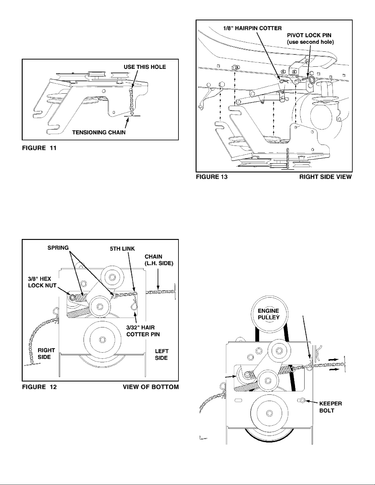
INSTALLING CLUTCH/IDLER ASSEMBLY
• Turn the ciutch/idier assembly upside down and
place the extra tensioning chain through the hole
shown in figure 11.
Hook the loose spring through the end of the
tensioning chain. See figure 12.
Hook the other end of the spring onto the bottom of
the bolt and nut which secure the idler pulley to the
upper idler arm. Hold the bolt head and assemble a
3/8" hex lock nut onto the bolt, leaving it loose
enough for the spring to pivot freely between the
two nuts. See figure 12.
Attach a 3/32" hairpin cotter to the chain, placing it
in the fifth link from the spring. See figure 12.
Assemble the short "V" belt onto the engine pulley
and then onto the large pulley on the clutch/idler
assembly. The belt must be placed to the inside of
the idler pulley and the keeper bolt. See figure 14.
IMPORTANT: Do Not assemble the "V" belt
around the outside of the keeper bolt.
Piace tension on the belt by pulling the ieft side
tensioning chain out as far as the 3/32" hairpin
cotter will allow. Secure the chain with a 1/8"
hairpin cotter. See figure 14.
Attach the clutch/idler assembly to the tractor frame
as follows. Hook the assembly's notched arms onto
the two shoulder bolts you assembled to the inside
of the tractor frame. Lift the front of the assembly
and attach it to the R.H. and L.H. hanger brackets
using two pivot lock pins and 1/8" hairpin cotters.
See figure 13.
Hold this drawing above you while viewing the
Clutch/idler Assembly from underneath the
tractor. Right and left in the drawing will be the
reverse of the viewer's right and left.
3/32" HAIRPIN
COTTER
1/8" HAIRPIN
COTTER
/
IDLER
PULLEY
Left Side
of Tractor
FIGURE 14 VIEWED FROM UNDERNEATH
 Loading...