

Page 1

Owner's Manual
®
POLY "10" ATV CART
Model No. 486.24339
CAUTION:
Before using this product, read
this manual and follow all
Safety Rules and
Operating Instructions.
IMPORTANT - READ THIS FIRST!!!
For Missing Parts or Assembly Questions
Please Call 217-728-8388
Mon.-Fri. 7 am - 5 pm CST.
FAX 217-728-2032 or e-mail info@agri-fab.com
Missing parts will be sent UPS in 24 hours directly to your home.
Sears, Roebuck and Co., Hoffman Estates, IL 60179 U.S.A.
www.sears.com/craftsman
PRINTED IN U.S.A.
• Safety
• Assembly
• Operation
• Maintenance
• Parts
FORM NO. 48228 (REV. 8/01)
Page 2

TABLE OF CONTENTS
SAFETY RULES ........................................................2
FULL SIZE HARDWARE CHART ............................. 3
CARTON CONTENTS ...............................................4
ASSEMBLY ................................................................4
OPERATION ..............................................................7
MAINTENANCE .........................................................7
STORAGE .................................................................. 7
REPAIR PARTS ILLUSTRATION ............................8
REPAIR PARTS LIST ................................................9
SLOPE GUIDE .........................................................11
PARTS ORDERING/SERVICE .................Back Page
WARRANTY
LIMITED ONE YEAR WARRANTY ON CRAFTSMAN POLY "10" ATV CART
For one year from the date of purchase, when this cart is maintained and lubricated according to the operating and
maintenance instructions in the owner's manual, Sears will repair any defect in material or workmanship free of charge.
If this cart is used for commercial or rental purposes, this warranty applies for only 90 days from the date of purchase.
This warranty does not cover repairs necessary because of operator negligence or abuse, including the failure to maintain
the equipment according to instructions contained in the owner's manual.
WARRANTY SERVICE IS AVAILABLE BY CONTACTING THE NEAREST SEARS SERVICE CENTER/DEPARTMENT
IN THE UNITED STATES.
This warranty applies only while this product is in the United States.
This warranty gives you specific legal rights, and you may also have other rights which vary from state to state.
Sears, Roebuck and Co. D/817 WA. Hoffman Estates, Chicago, IL 60179
SAFETY
Any power equipment can cause injury if operated improperly or if the user does not understand how to operate
the equipment. Exercise caution at all times, when using power equipment.
• Read this owners manual before attempting to
assemble or operate the cart.
• Read the vehicle owners manual and know how to
operate your vehicle before using the cart attachment.
• Do not at any time carry passengers in this cart. It has
not been designed to carry passengers.
• Never allow children to operate the vehicle or the cart
attachment.
• Do not allow adults to operate the vehicle or cart
attachment without proper instructions.
• Always begin with the transmission in first (low) and
gradually increase speed as conditions permit.
• Tow the cart at reduced speed over rough terrain and
hillsides or near creeks and ditches to prevent tipping
over and loss of control. Do not drive too close to a
creek or ditch.
• Vehicle braking and stability may be affected with the
attachment of this cart. Do not fill cart to maximum
weight capacity without checking the capability of the
towing vehicle to safely pull and stop with the cart
attached.
• Before operating vehicle on any grade (hill) refer to
the safety rules in the vehicle owner's manual concerning safe operation on slopes. Refer also to the
slope guide on page 11 of this manual. Stay off
steep slopes!
• Do not tow this cart on highways or on public thor-
oughfares.
• Maximum towing speed is 10 m.p.h.
• Follow maintenance and lubrication instructions as
outlined in this manual.
Look for this symbol to point out important safety precautions. It mean--Attention!!
Become alert!! Your safety is involved.
2
Page 3
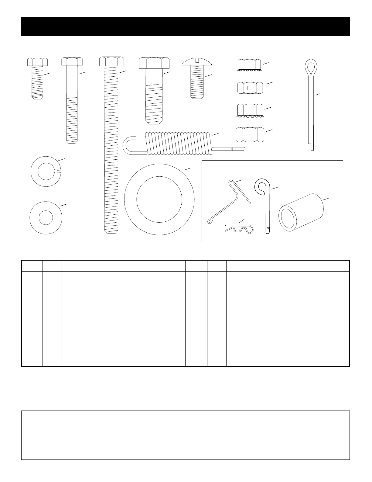
HARDWARE PACKAGE CONTENTS
HARDWARE SHOWN FULL SIZE
F
A
B
C
D
E
G
J
H
K
L
REF. QTY. DESCRIPTION
A 4 Hex Bolt, 1/4" x 3/4"
B 4 Hex Bolt, 1/4" x 1-3/4"
C 1 Hex Bolt, 5/16" x 3-3/4"
D 2 Hex Bolt, 3/8" x 1-1/4"
E 8 Truss Head Bolt, 5/16" x 3/4"
F 8 Hex Nut, 1/4"
G 1 Hex Lock Nut, 5/16"
H 10 Hex Nut, 5/16"
I 2 Hex Nut, 3/8"
N
I
M
Not Shown Full Size
O
P
Q
REF. QTY. DESCRIPTION
J 2 Cotter Pin, 1/8" x 1-1/2"
K 2 Lock Washer, 3/8"
L 4 Flat Washer, 1/4"
M 4 Flat Washer, 1"
N 1 Extension Spring
O 1 Spring Puller
P 1 Hitch Pin
Q 1 Hair Cotter Pin 1/8"
R 2 Spacer Tube
R
The model number and serial numbers will be found on a
decal attached to the wheel support.
You should record both the serial number and the date of
purchase and keep in a safe place for future reference.
MODEL NUMBER: 486.24339
SERIAL NUMBER: __________________
DATE OF PURCHASE: __________________
3
Page 4

CARTON CONTENTS
ASSEMBLY
1. Poly Tray
2. Wheel Support
3. Latch Stand Plate
4. Latch Stand Bracket
5. Axle
6. Wheels (2)
7. Draw Bar Tongue
1
5
6
7
8. Latch Lock Lever
9. Hitch Bracket
3
2
4
8
9
TOOLS REQUIRED FOR ASSEMBLY
(1) Screwdriver
(1) Pliers
(2) 7/16" Wrenches
(2) 1/2" Wrench
(2) 9/16" Wrenches
• Remove the hardware pack and all loose parts from
the carton. Be sure the carton is empty before
discarding.
• Lay out and identify all the parts and hardware as
shown on pages 3 and 4.
• Place the latch lock lever through the slot in the
draw bar tongue as shown in figure 1. Assemble
the 5/16" x 3-3/4" hex bolt through the tongue, the
lever and two 5/16" hex nuts (one on each side of
the lever). Assemble the 5/16" hex lock nut onto
the end of the bolt and tighten so that the bolt can
still rotate freely. Tighten the two 5/16" hex nuts
against the sides of the latch lock lever so that the
lever is centered in the slot. See figure 1.
DRAWBAR TONGUE
5/16" x 3-3/4"
HEX BOLT
FIGURE 1
5/16" HEX
NUTS
LATCH
LOCK
LEVER
5/16" HEX
LOCK NUT
4
Page 5

• Attach the short end of the spring to the hole in the
latch lock lever. Use the spring puller to attach the
long end of the spring to the square hole in the
tongue. The hooked end of the puller should face
away from the tongue as shown in figure 2.
LONG END
OF SPRING
• Assemble the axle and drawbar tongue to the
wheel support, with the open side of tongue facing
away from the wheel support. Fasten the axle to
the wheel support using four 1/4" x 1-3/4" hex bolts
and 1/4" hex nuts. Tighten. See figure 4.
1/4" x 1-3/4"
HEX BOLT
AXLE
DRAW BAR
TONGUE
LATCH LOCK
LEVER
FIGURE 2
• Assemble the hitch bracket to the drawbar tongue
using two 3/8" x 1-1/4" hex bolts, 3/8" lock washers
and 3/8" hex nuts. Tighten. See figure 3.
• Assemble hitch pin to tongue/ hitch bracket and secure
with 1/8" hair cotter pin. See figure 3.
SPRING PULLER
HITCH PIN
3/8" x 1-1/4"
HEX BOLT
HITCH
BRACKET
TONGUE
1/4" HEX NUT
WHEEL
SUPPORT
FIGURE 4
• Assemble a spacer tube, a 1" flat washer, a wheel
(valve stem facing out) and another 1" flat washer
onto the axle as shown in figure 5. Insert a cotter
pin through the axle, spreading the ends. Repeat
on other end of axle.
NOTE: Use the grease fitting to fill the wheel hub with
automotive type grease after the wheel is
assembled onto the axle.
WHEEL
FLAT
WASHER
SPACER
TUBE
AXLE
1/8" HAIR
COTTER
PIN
FIGURE 3
3/8" LOCK
WASHER
3/8" HEX
NUT
FLAT
WASHER
COTTER PIN
FIGURE 5
5
Page 6

• Assemble the latch stand plate and the latch stand
T
bracket to the bottom of the poly tray using four
1/4" x 3/4" hex bolts, 1/4" flat washers and 1/4"
hex nuts. Tighten. See figure 6.
1/4" x 3/4"
HEX BOLT
1/4" FLAT
WASHER
LATCH
STAND PLATE
LATCH STAND
BRACKET
FIGURE 6
1/4" HEX NU
• Place the poly tray down onto the wheel support,
positioning it so that the latch stand bracket snaps
under the latch lock lever. Fasten the tray to the
wheel support using eight 5/16" x 3/4" truss head
bolts and 5/16" hex nuts as shown in figure 7.
Tighten.
5/16" x 3/4"
TRUSS HEAD
BOLT
FIGURE 7
5/16" HEX
NUT
LATCH LOCK
LEVER
6
Page 7

OPERATION
KNOW YOUR CART
Read this owner's manual and safety rules before
operating your cart.
Compare the illustration below with your cart to familiarize
yourself with the various controls and their locations.
LATCH LOCK LEVER
LATCH LOCK LEVER Locks the front of the cart to
the tongue and releases it for dumping.
HOW TO USE YOUR
• Use the slope guide provided on page 11 of this
manual to determine whether slope angle is too
steep for safe operation.
CAUTION: Vehicle braking and stability
may be affected with the addition of an
accessory or an attachment. Be aware of
changing conditions on slopes.
• For best handling and traction, distribute the weight
of the load evenly in the cart.
• Always test to make sure your vehicle has adequate
towing and braking capabilities whenever hauling a
substantial amount of weight in your cart. Use extra
caution when operating on slopes.
• To dump material from the cart, release the spring
latch on the tongue by pulling the latch lock lever
forward, away from the cart. The cart bed will then
tilt backwards to empty its contents. After emptying,
pull the front of the bed down toward the cart tongue
until the latch snaps into place.
• The maximum towing speed for this cart is 10 m.p.h.
DO NOT EXCEED WEIGHT CAPACITY OF CART
(See the specifications on this page.)
One cubic foot of dirt weighs approximately 150 lbs.
• Refer to the vehicle owners manual for instructions
on safe operation on slopes.
CAUTION: To avoid possible injury,
before releasing the latch be sure that
no one is near the cart.
MAINTENANCE/STORAGE
CUSTOMER RESPONSIBILITIES
• Read and follow the maintenance schedule and the maintenance procedures listed in this section.
MAINTENANCE SCHEDULE
Fill in dates as you
complete regular service.
Check for loose fasteners X
Check for worn or damaged parts X
Check tire pressure X
Lubricate X
Clean X
Before each use
Every season
After each use
Before storage
SCHEDULED MAINTENANCE
the cart for any bolts and nuts which may have
loosened. Retighten any loose bolts and nuts.
• Keep tires filled. The maximum recommended
pressure is 10 lbs.
• Lubricate the latch lock assembly each season
using a light machine oil.
• Apply grease through the grease fittings to the
wheel hubs each season.
• Wipe off or rinse the cart after each use.• Before each use make a thorough visual check of
STORAGE
• Clean thoroughly before storing.
• Remove any rust from painted surfaces and coat
with touch up paint.
• Store in a clean, dry area.
Service Dates
7
Page 8

PARTS
REPAIR PARTS FOR MODEL 486.24339
23
11
12
20
7
21
3
13
12
22
2
22
8
B
16
1
5
21
6
25
22
17
14
19
2
8
4
B
9
24
18
27
15
10
26
Page 9

REPAIR PARTS FOR MODEL 486.24339
REF. PART QTY. DESCRIPTION
NO. NO.
1 47019 1 Poly Tray
2 24528 1 Axle, 1"
3 47049 2 Wheel
4 24758 1 Draw Bar Tongue
5 24386 1 Latch Stand Plate
6 24497 1 Latch Stand Bracket
7 24527 1 Wheel Support
8 24498 1 Latch Lock Lever
9 47407 1 Hex Bolt, 5/16-18 x 3-3/4"
10 23475 1 Hitch Bracket
11 43093 2 Cotter Pin, 1/8" x 1-1/2"
12 43601 4 Washer, Flat 1.59" O.D. x 1" I.D.
13 47453 2 Spacer Tube, 3-1/8" Lg.
14 43064 1 Hex Lock Nut, 5/16-18*
15 43015 2 Hex Nut, 3/8-16*
16 43088 4 Flat Washer, 1/4"
17 43087 2 Hex Bolt, 3/8-16 x 1-1/4" *
18 43003 2 Lock Washer, 3/8" *
19 1509-69 4 Hex Bolt, 1/4-20 x 1-3/4" *
20 43814 8 Truss Head Bolt, 5/16-18 x 3/4"
21 46978 8 Hex Nut, 1/4-20 (SEMS)
22 46980 10 Hex Nut, 5/16-18 (SEMS)
23 43012 4 Hex Bolt, 1/4-20 x 3/4" *
24 47408 1 Extension Spring
25 23353 1 Hitch Pin
26 43343 1 Hair Cotter Pin, 1/8"
27 47622 1 Spring Puller
48228 1 Owner's Manual
* Purchase Common Hardware Locally
9
Page 10

NOTES
10
Page 11

SLOPE GUIDE
(Keep this sheet in a safe place for future reference.)
Use this guide to determine if a slope is safe for the operation of your tractor and cart.
Refer also to the instructions in your vehicle owners manual.
11
SLOPE IN EXCESS OF 10 DEGREES. BE SURE OF YOUR
TRACTOR'S TOWING AND BRAKING CAPABILITIES BEFORE
CAUTION: DO NOT OPERATE YOUR TRACTOR AND CART ON A
OPERATING ON A SLOPE. AVOID ANY SUDDEN TURNS OR
MANEUVERS WHILE ON A SLOPE.
Page 12

Get it fixed, at your home or ours!
For repair of major brand appliances in your own home…
no matter who made it, no matter who sold it!
1-800-4-MY-HOME
(1-800-469-4663)
www.sears.com
SM
Anytime, day or night
To bring in products such as vacuums, lawn equipment and electronics
for repair, call for the location of your nearest
1-800-488-1222
www.sears.com
Sears Parts & Repair Center.
Anytime, day or night
For the replacement parts, accessories and owner’s manuals
that you need to do-it-yourself, call Sears PartsDirect
1-800-366-PART
(1-800-366-7278)
www.sears.com/partsdirect
6 a.m. – 11 p.m. CST,
7 days a week
SM
!
To purchase or inquire about a Sears Service Agreement:
1-800-827-6655
7 a.m. – 5 p.m. CST, Mon. – Sat.
Para pedir servicio de reparación a domicilio,
y para ordenar piezas con entrega a domicilio:
1-888-SU-HOGAR
(1-888-784-6427)
SM
HomeCentral
® Registered Trademark / ™ Trademark of Sears, Roebuck and Co.
© Sears, Roebuck and Co.
® Marca Registrada / ™ Marca de Fábrica de Sears, Roebuck and Co.
Au Canada pour service en français:
1-877-LE-FOYER
(1-877-533-6937)
SM
SM
 Loading...