

Page 1
®
www.sears.com/craftsman
this manual and follow all Safety
Safety
Assembly
Operation
Maintenance
Parts
STOP
DO NOT RETURN TO STORE
For Missing Parts or Assembly
Questions Call 1-866-576-8388
Page 2

TABLE OF CONTENTS
.............................................................
Warranty
...................................................................
Assembly
..................................................................
..................................................................
.............................................................
.....................................................................
.....................................................
...........................................................
Any power equipment can cause injury if operated improperly or if the user does not understand how to operate the equipment.
• Read this owners manual before attempting to
• Read the vehicle owners manual and know how to
• Do not at any time carry passengers in this cart. It has
• Never allow children to operate the tractor or the cart
• Do not allow adults to operate the tractor or cart
• Always begin with the transmission in fi rst (low) and
• Tow the cart at reduced speed over rough terrain and
• Vehicle braking and stability may be affected with the
weight capacity without checking the capability of the
towing vehicle to safely pull and stop with the cart
• Before operating vehicle on any grade (hill) refer to
• Do not tow this cart on highways or public
thoroughfares.
• Maximum towing speed is 10 m.p.h.
• Do not load more weight into the push cart than you
• Follow maintenance and lubrication instructions as
Your safety is involved.
When operated and maintained according to the instructions supplied with it, if this Convertible Cart fails due to a defect in
This warranty gives you specifi c legal rights, and you may also have other rights which vary from state to state.
MODEL NUMBER: 486.243201
SERIAL NUMBER: __________________
DATE OF PURCHASE: __________________
The model number and serial numbers will be found on
You should record both the serial number and the date of
SAFETY
WARRANTY
Page 3
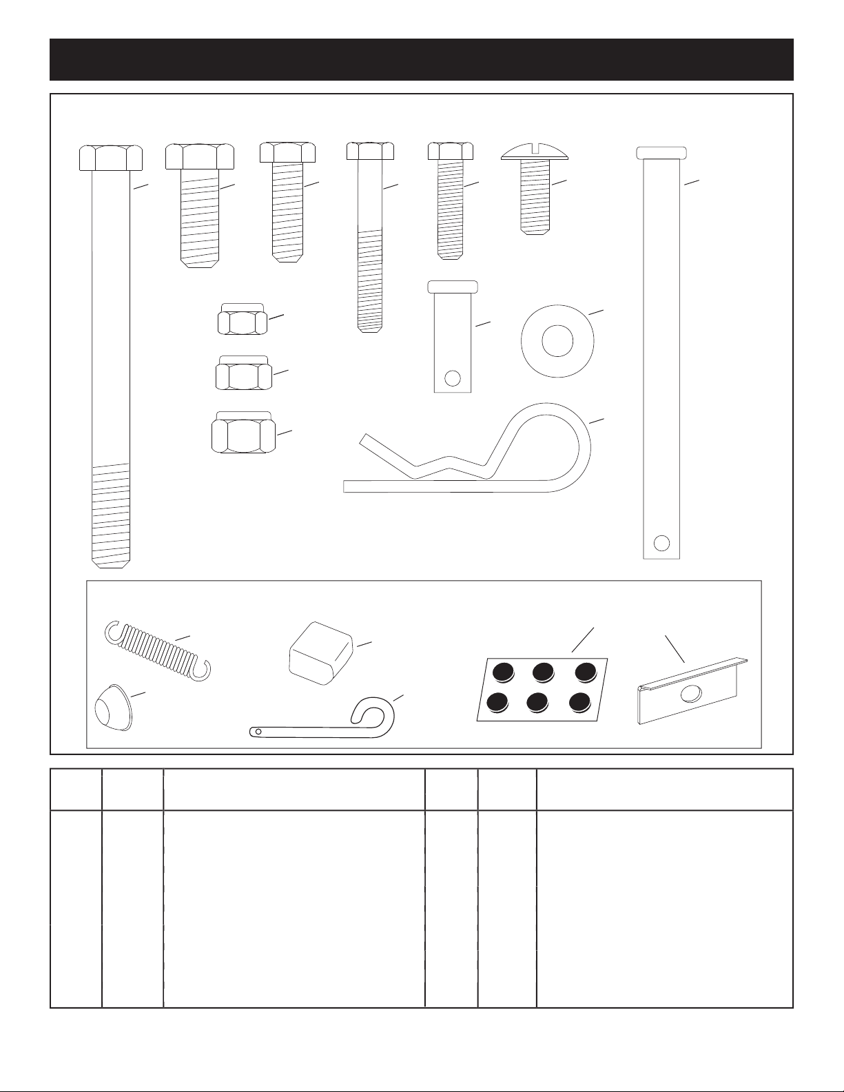
HARDWARE PACKAGE CONTENTS
No.
K 10 Nylock Nut, 5/16"
L 3 Nylock Nut, 3/8"
M 3 Hairpin Cotter, 1/8"
N 1 Extension Spring
O 1 Plastic Cap
P 2 Hub Cap
Q 1 Hitch Pin
R 6 Noise Reduction Pad
S 2 Axle Clip
No.
A 1 Hex Bolt, 3/8" x 4"
B 2 Hex Bolt, 3/8" x 1"
C 2 Hex Bolt, 5/16" x 1"
D 6 Hex Bolt, 1/4" x 1-3/4"
E 3 Hex Bolt, 1/4" x 1"
F 8 Truss Head Bolt, 5/16" x 3/4" Lg.
G 1 Clevis Pin, 3/8" x 4"
H 1 Clevis Pin, 3/8" x 1"
I 6 Flat Washer, 1/4"
J
9 Nylock Nut, 1/4"
K
L
M
N
J
Q
Not Shown Full Size
HARDWARE SHOWN FULL SIZE
GF
C
BA
I
O
P
H
D
E
R
S
Page 4
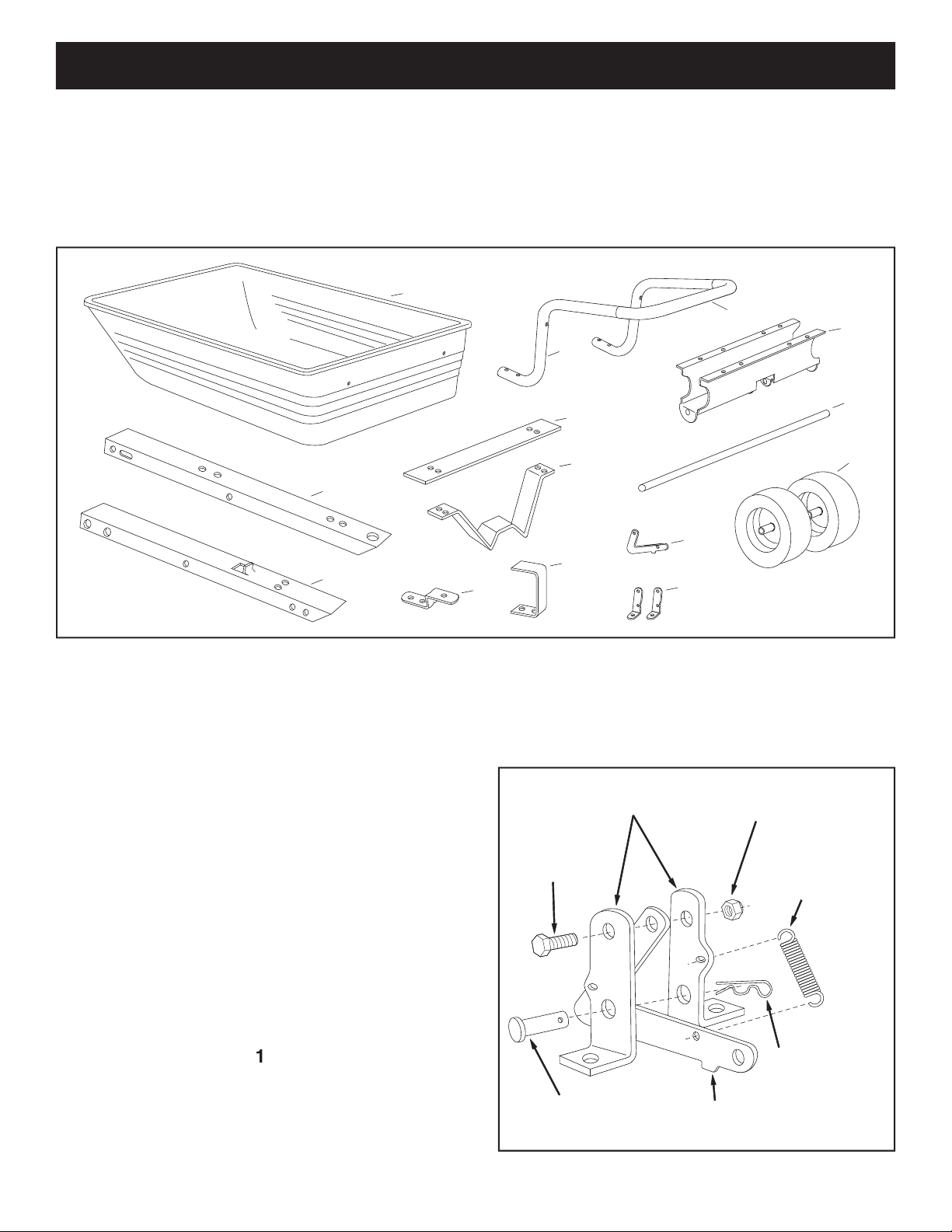
ASSEMBLY
• Remove the hardware pack and all loose parts
from the carton. Be sure the carton is empty before
• Lay out all the parts shown on pages 3 and 4.
All 1/4" fl at washers should be assembled so that
they rest directly against the poly tray surface.
• Assemble the latch lock between the latch mount
TOOLS REQUIRED FOR ASSEMBLY
LATCH LOCK
(N) EXTENSION
SPRING
(J) 1/4" NYLOCK NUT
(E) 1/4" x 1"
HEX BOLT
LATCH MOUNT
BRACKETS
(M) 1/8" HAIRPIN
COTTER
(H) 3/8" x 1"
CLEVIS PIN
7
13
11
1
6
12
9
10
5
8
3
4
2
14
• Insert the 3/8" x 1" clevis pin (H) through the holes
Page 5

• Assemble the hitch bracket to the front tongue using
two 3/8" x 1" hex bolts (B) and 3/8" hex nylock nuts
Tighten.
• Assemble the leg stand bracket to the front tongue
Tighten.
• Assemble the latch lock subassembly to the rear
tongue using two 1/4" x 1" hex bolts (E) and 1/4"
Tighten.
• Assemble the plastic cap (O) to the front end of the
• Lay the rear tongue (open side facing up) onto the
Wheel Support. Assemble the axle through the wheel
tongue.
FRONT
TONGUE
(B) 3/8" x 1"
HEX BOLT
(L) 3/8" NYLOCK NUT
HITCH
BRACKET
LEG STAND
BRACKET
(C) 5/16" x 1"
HEX BOLT
(K) 5/16" NYLOCK NUT
• Place the front tongue inside the rear tongue as
Tighten,
leaving the nut just loose enough that the
tongues can pivot freely.
• Insert the 3/8" x 4" clevis pin (G) through the tongues
LATCH LOCK
SUB-ASSEMBLY
(E) 1/4" x 1"
HEX BOLT
(J) 1/4" NYLOCK NUT
REAR
TONGUE
(O) PLASTIC CAP
WHEEL
SUPPORT
REAR
TONGUE
AXLE
FRONT
TONGUE
(L) 3/8"
NYLOCK NUT
(A) 3/8" x 4"
HEX BOLT
(G) 3/8" x 4"
CLEVIS PIN
(M) 1/8" HAIRPIN
COTTER
Page 6

• Assemble an axle clip (S) and a wheel with the valve
• Insert two 1/4" x 1-3/4" hex bolts (D) through the
with two 1/4" fl at washers (I) and 1/4" nylock nuts (J).
• Attach two noise reduction pads (R) to the bottom of
the latch stand bracket.
• Turn the assembled tongue, wheel support and
wheels over to the upright position. Place the latch
the wheel support and latch stand bracket. Fasten
the tray to the wheel support using eight 5/16" x 3/4"
truss head bolts (F) and 5/16" nylock nuts (K).
tighten yet.
• Place the latch stand plate between the latch stand
(P) HUB CAP
WHEEL
AXLE
(S) AXLE CLIP
(K) 5/16"
NYLOCK NUTS
(F) 5/16" x 3/4"
TRUSS HEAD
BOLT
LATCH STAND
BRACKET
LATCH
STAND
PLATE
PADS (R)
(D) 1/4" x 1-3/4"
HEX BOLT
(I) 1/4" FLAT
WASHER
(J) 1/4" NYLOCK
NUT
LATCH STAND
BRACKET
Page 7

• Align the holes in the handle with the holes in the
x 1-3/4" hex bolts (D), 1/4" fl at washers (I) and 1/4"
Tighten.
• At this time
tighten
all bolts which were left loose.
(D) 1/4" x 1-3/4"
HEX BOLT
(I) 1/4" FLAT
WASHER
(J) 1/4"
NYLOCK
NUT
• Assemble the hitch pin (Q) through the tongue and
FRONT
TONGUE
(G) 3/8" x 4"
CLEVIS PIN
(H) 3/8" x 1"
CLEVIS PIN
LATCH LOCK
HITCH
BRACKET
(M) 1/8" HAIRPIN
COTTER
(Q) HITCH PIN
PADS (R)
PADS (R)
• Attach two noise reduction pads (R) on each side of
the front tongue.
Page 8

OPERATION
To avoid possible injury,
• Use the slope guide provided on page 11 of this
for safe operation.
• Always test to make sure your tractor has adequate
towing and braking capabilities whenever hauling a
• For best handling and traction, distribute the weight of
the load evenly in the cart.
• To dump material from the cart, remove the 1" long
• To convert the cart for towing, remove the plastic cap
from the tongue. Remove the 4" long clevis pin and
tongue outward and secure it in the towing position
• The maximum towing speed for this cart is 10 m.p.h.
• Refer to the vehicle owners manual for instructions on
Vehicle braking and stability
FRONT
TONGUE
3/8" x 4"
CLEVIS PIN
LATCH LOCK
CLEVIS PIN
LATCH LOCK
LEG STAND
BRACKET
HANDLE TUBE
HITCH PIN
Page 9

Leave the latch lock clevis pin in place at
• To convert the cart for push operation, remove the 4"
tongue in the towing position. (See drawing on page
MAINTENANCE SCHEDULE
complete regular service.
After each use
Twice a year
Every season
Before storage
MAINTENANCE/STORAGE
Check for loose fasteners X
Check for worn or damaged parts X
Check tire pressure X
Lubricate X
Clean X X
the maximum recommended pressure
• Check for loose fasteners before each use.
• Check for worn or damaged parts before each use.
• Keep tires fi lled to recommended tire pressure printed
• At the beginning of each season, using a light
• Grease or oil the wheel bearings periodically (at least
fi gure 13.
Tires:
14" x 4" Pneumatic
5/8" Dia. Steel
Up to 500 Lbs. Max.
Approx. Sh. Wt.
55 Lbs.
• Clean thoroughly before storing.
• Remove any rust from painted surfaces and coat with
touch up paint.
• Store in a dry area.
• For best handling, and to help prevent accidental
tipping, distribute the weight of the load evenly in the
• Do not load more weight into the push cart than you
• To dump material from the push cart, lift up on the
that the latch
the clevis pin to prevent accidental release of the
Read and follow the maintenance schedule and the procedures listed in the maintenance section.
OIL
OIL
GREASE
Page 10

PARTS
REF PART QTY DESCRIPTION
NO NO
A
A
30
19
1
17
21
6
7
17
17
30
9
22
22
32
3
2
33
5
29
15
13
20
14
28
25
25
10
24
11
17
23
16
2
18
18
27
26
8
31
4
12
25
19
2 24908 1 Axle
3 48497 2 Wheel Assembly
4 24392 1 Tongue, Front
5 24391 1 Tongue, Rear
6 24386 1 Latch Stand Plate
7 23297 1 Latch Stand Bracket
8 48834 1 Handle Tube
9 24527 1 Wheel Support
10 62020 1 Latch Lock
11 23470 2 Bracket, Latch Mounting
12 23353 1 Hitch Pin
13 23014 1 Hitch Bracket
14 24390 1 Leg Stand Bracket
15 47029 1 Clevis Pin, 3/8" x 4"
16 45091 1 Clevis Pin 3/8" x 1"
17 47189 9 Nylock Nut 1/4-20 Thread *
18 HA21362 3 Nylock Nut, 3/8-16 Thread *
19 43088 6 Washer, Flat 1/4" Std. Wrought
20 43001 2 Hex Bolt, 3/8-16 x 1" Lg. *
21 43814 8 Truss Hd Bolt, 5/16-18 x 3/4" Lg.*
22 47810 10 Nylock Nut, 5/16-18 Thread *
23 43661 3 Hex Bolt, 1/4-20 x 1" *
24 43000 1 Extension Spring
25 43343 3 Hairpin, Cotter 1/8"
26 48499 2 Hub Cap
27 47038 1 Plastic Cap
28 43063 2 Hex Bolt, 5/16-18 x 1" Lg. *
29 43036 1 Hex Bolt, 3/8-16 x 4" Lg. *
30 1509-69 6 Hex Bolt, 1/4-20 x 1-3/4" Lg. *
31 48836 1 Foam Grip
32 48661 6 Noise Reduction Pad
33 25910 2 Axle Clip, 5/8"
40303 1 Owner's Manual
REF PART QTY DESCRIPTION
NO NO
Page 11

WARNING: To avoid serious injury, operate your tractor up and
down the face of slopes, never across the face. Do not operate
on slopes greater than 10 degrees. Make turns gradually to
prevent tipping or loss of control. Exercise extreme caution
when changing direction on slopes. Braking may be affected by
tractor attachment. Reduce speed on slopes.
1. Fold this page along dotted line indicated above.
2. Hold page before you so that its left edge is vertically parallel to a tree
trunk or other upright structure.
3. Sight across the fold in the direction of hill slope you want to measure.
4. Compare the angle of the fold with the slope of the hill.
ONLY RIDE UP AND DOWN HILL,
NOT ACROSS HILL
F
O
L
D
A
L
O
N
G
D
O
T
TE
D
L
I
N
E
T
H
I
S
I
S
A
1
0
D
E
G
R
E
E
S
L
O
P
E
10 DEGREES MAX.
SUGGESTED GUIDE FOR SIGHTING SLOPES FOR SAFE OPERATION
OF TRACTOR WITH ATTACHMENT
Page 12

® Registered Trademark / TM Trademark /SM Service Mark of Sears Brands, LLC
® Marca Registrada /
TM
Marca de Fábrica / SM Marca de Servicio de Sears Brands, LLC
MC
Marque de commerce / MD Marque déposée de Sears Brands, LLC © Sears Brands, LLC
Get it fixed, at your home or ours!
Your Home
For repair – in your home – of all major brand appliances,
lawn and garden equipment, or heating and cooling systems,
no matter who made it, no matter who sold it!
For the replacement parts, accessories and
owner’s manuals that you need to do-it-yourself.
For Sears professional installation of home appliances
and items like garage door openers and water heaters.
1-800-4-MY-HOME
®
(1-800-469-4663)
Call anytime, day or night (U.S.A. and Canada)
www.sears.com www.sears.ca
Our Home
For repair of carry-in items like vacuums, lawn equipment,
and electronics, call or go on-line for the location of your nearest
Sears Parts & Repair Center.
1-800-488-1222
Call anytime, day or night (U.S.A. only)
www.sears.com
To purchase a protection agreement (U.S.A.)
or maintenance agreement (Canada) on a product serviced by Sears:
1-800-827-6655 (U.S.A.) 1-800-361-6665 (Canada)
Para pedir servicio de reparación
a domicilio, y para ordenar piezas:
1-888-SU-HOGAR
®
(1-888-784-6427)
Au Canada pour service en français:
1-800-LE-FOYER
MC
(1-800-533-6937)
www.sears.ca
 Loading...