

Page 1
Owner's Manual
®
STOP
DO NOT RETURN TO STORE
For Missing Parts or Assembly
Questions Call 1-866-576-8388
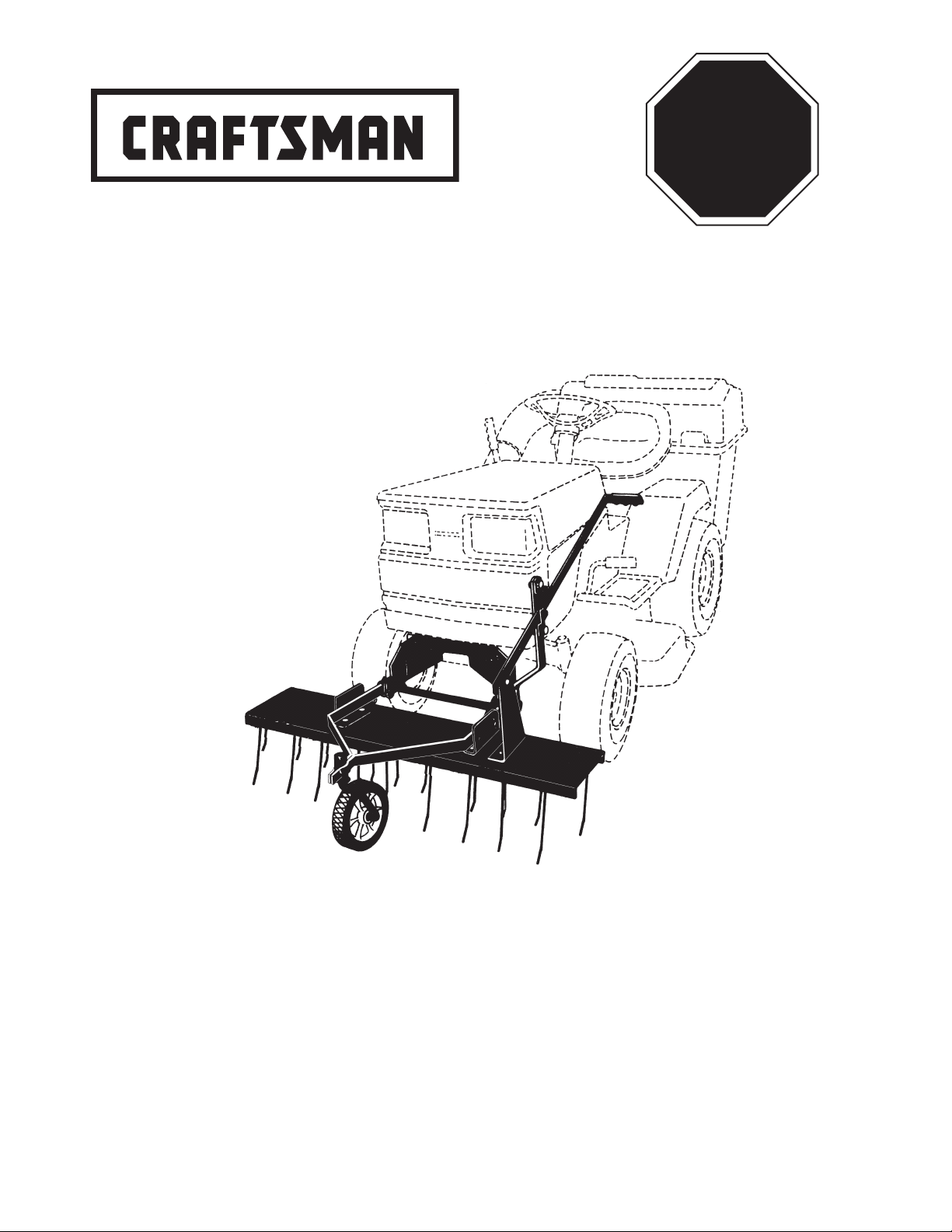
40" FRONT MOUNT
TINE DETHATCHER
Model No. 486.24312
CAUTION:
Before using this product, read
this manual and follow all Safety
Rules and Operating Instructions.
Sears, Roebuck and Co., Hoffman Estates, IL 60179 U.S.A.
www.sears.com/craftsman
PRINTED IN U.S.A.
• Safety
• Assembly
• Operation
• Maintenance
• Parts
FORM NO. 40375 (REV. 2/28/07)
Page 2

TABLE OF CONTENTS
SAFETY RULES ..............................................................2
FULL SIZE HARDWARE CHART ....................................3
CARTON CONTENTS ..................................................... 4
ASSEMBLY ......................................................................4
OPERATION ............................................................... 9-10
MAINTENANCE/STORAGE ............................................ 9
SERVICE/ADJUSTMENTS ........................................... 10
REPAIR PARTS ........................................................... 11
PARTS ORDERING/SERVICE ........................Back Cover
WARRANTY
ONE YEAR FULL WARRANTY
When operated and maintained according to the instructions supplied with it, if this Dethatcher fails due to a defect in material
or workmanship within one year from the date of purchase, call 1-800-4-MY-HOME® to arrange for free repair (or replacement
if repair proves impossible).
If this product is used for commercial or rental purposes, this warranty applies for only 90 days from the date of purchase.
This warranty gives you specic legal rights, and you may also have other rights which vary from state to state.
Sears, Roebuck and Co., D817WA, Hoffman Estates, IL 60179
The model number and serial numbers will be found on a
decal attached to the dethatcher.
You should record both the serial number and the date of
purchase and keep in a safe place for future reference.
MODEL NUMBER: 486.24312
SERIAL NUMBER: __________________
DATE OF PURCHASE: __________________
SAFETY
Any power equipment can cause injury if operated improperly or if the user does not understand how to operate the equipment.
Exercise caution at all times, when using power equipment.
• Read safety rules in the vehicle owners manual and
know how to operate your equipment, before using
the tine dethatcher.
• Never operate vehicle and tine dethatcher attachment
without wearing substantial footwear, and do not allow
anyone to ride or sit on the tine dethatcher.
• Never allow children to operate the tractor or
dethatcher attachment, and do not allow adults to
operate without proper instructions.
• Eye Protection should be worn when operating the
tine dethatcher.
• Always begin with transmission in rst (low) gear,
and gradually increase speed as conditions permit.
Recommended maximum operating speed is 3 M.P.H.
• Always stop vehicle and lift dethatcher to transport
position before making short turns.
• When de-thatching do not drive too close to a creek or
ditch and be alert for holes and other hazards which
could cause you to lose control of the vehicle.
• Before operating vehicle on any grade (hill) refer
to the safety rules in the vehicle owners manual
concerning safe operation on slopes. STAY OFF
STEEP SLOPES.
• This equipment is not meant for street or highway use.
Watch for trafc when de-thatching near highways.
• Vehicle and attachments should be stopped and
inspected for damage after striking a foreign object.
• Check all nuts, bolts and screws frequently making
sure they are tight and the equipment is in safe
working condition.
• Follow the maintenance instructions as outlined in this
owners manual.
Look for this symbol to point out important safety precautions. It means — Attention!! Become
alert!! Your safety is involved.
2
Page 3
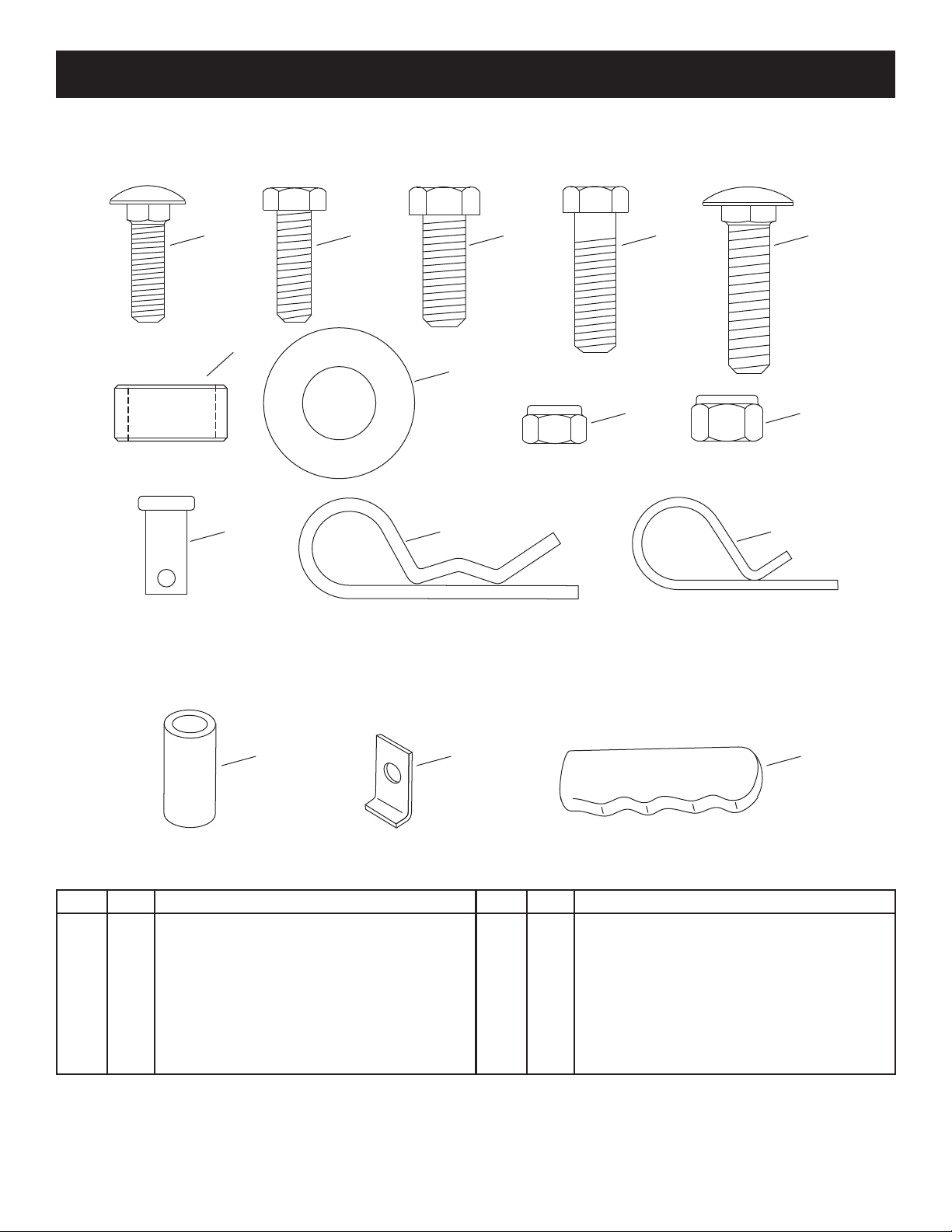
HARDWARE PACKAGE CONTENTS
A
J
N O
K L
B
D
G
H
I
SHOWN FULL SIZE
NOT SHOWN FULL SIZE
C
E
F
M
KEY QTY DESCRIPTION
A 12 Carriage Bolt, 5/16-18 x 1" Lg.
B 2 Hex Bolt, 5/16-18 x 1" Lg.
C 4 Hex Bolt, 3/8-16 x 1"
D 2 Hex Bolt, 3/8-16 x 1-1/4"
E 4 Carriage Bolt, 3/8-16 x 1-1/2"
F 4 Spacer, .8" x 1" x .5"
G 4 Flat Washer, 5/8" SAE
H 14 Nylock Nut, 5/16-18
KEY QTY DESCRIPTION
I 10 Nylock Nut, 3/8-16
J 1 Clevis Pin, 3/8" x 3/4"
K 6 Hairpin Cotter, 1/8" (large)
L 1 Hairpin Cotter, 3/32" (small)
M 1 Axle Bushing
N 2 Keeper Plate
O 1 Handle Grip
3
Page 4
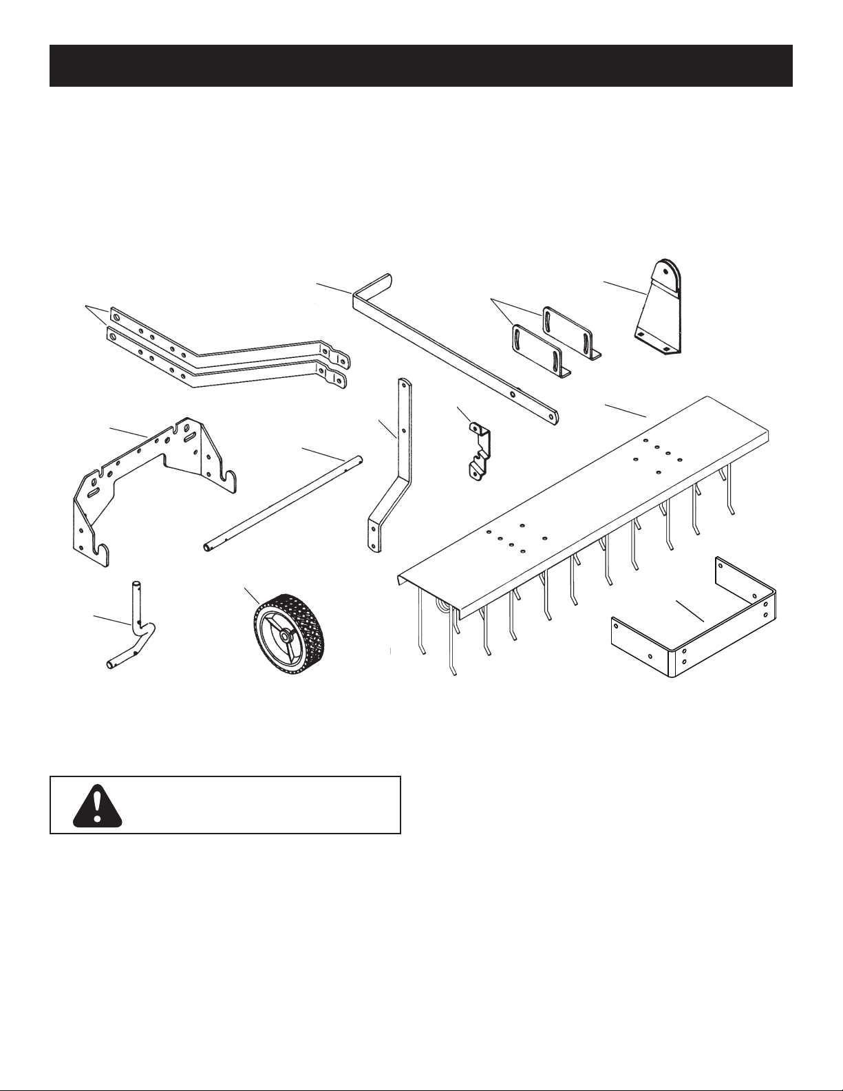
CARTON CONTENTS
2
1
5
6
7
8
9
10
11
12
3
4
ASSEMBLY
1. Mounting Arms (2)
2. Lift Handle
3. Angle Mounting Brackets (2)
4. Lift Handle Bracket
5. Hitch Bracket
6. Axle
7. Wheel
8. Mounting Shaft
9. Lift Handle Arm
10. Handle Lock Bracket
11. Tine Shield
12. Frame Mount Bracket
Stop engine and let mufer cool before
attempting to install dethatcher hitch
brackets.
TOOLS REQUIRED FOR ASSEMBLY
(2) 1/2" Wrenches
(2) 9/16" Wrenches
REMOVAL OF PARTS FROM CARTON
• Remove all parts and hardware packages from the
carton. Lay out all parts and hardware and identify
using the illustrations on pages 3 and 4.
REMOVAL OF PARTS FROM TRACTOR
• Remove any front mounted attachments which may
be installed on your tractor.
• Mark all loose parts and save for reassembly.
4
Page 5
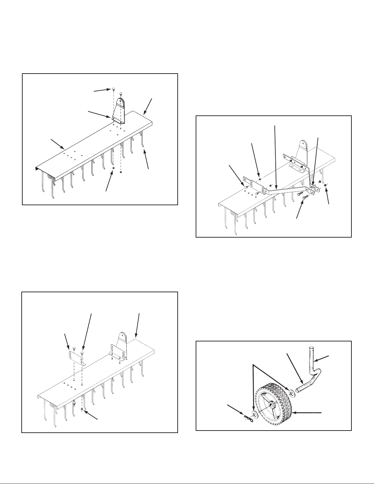
ASSEMBLING DETHATCHER
APPLY OIL
5/8" WASHER
1/8" HAIRPIN
COTTER
WHEEL
AXLE
TINE
SHIELD
5/16" x 1"
CARRIAGE BOLT
HANDLE LIFT
BRACKET
5/16" NYLOCK NUT
TINES POINT
TO FRONT
LEFT END
5/16" x 1"
CARRIAGE BOLT
ANGLE
MOUNTING
BRACKET
5/16" NYLOCK NUT
TINE
SHIELD
5/16" x 1"
CARRIAGE BOLT
MOUNTING ARM
5/16" NYLOCK NUT
3/8" NYLOCK
NUT
3/8" x 1-1/4"
HEX BOLT
AXLE BUSHING
1. Assemble handle lift bracket to rear set of holes on
left end of tine shield. Use two 5/16" x 1" carriage
bolts and 5/16" nylock hex nuts. Tighten. See gure 1.
3. Assemble mounting arms to inside of angle mounting
brackets using four 5/16" x 1" carriage bolts and 5/16"
nylock hex nuts. Fasten through rear set of holes in
mounting arms. Do not tighten until dethatcher is
mounted to tractor. See gure 3.
4. Loosely assemble front ends of mounting arms
together using two 3/8" x 1-1/4" hex bolts and 3/8"
nylock hex nuts. Place axle bushing between front
ends of mounting arms, centering bushing up and
down. Tighten bolts securely in front ends of
mounting arms. See gure 3.
FIGURE 1
2. Assemble angle mounting brackets to tine shield
using four 5/16" x 1" carriage bolts and 5/16" nylock
hex nuts. Tighten. See gure 2.
FIGURE 3
5. Apply a light coating of oil to the axle.
6. Assemble a 5/8" washer, the wheel (long end of hub
rst) and another 5/8" washer onto axle. Secure with a
1/8" hairpin cotter. See gure 4.
FIGURE 2
FIGURE 4
5
Page 6

7. Assemble a 5/8" washer onto axle. Insert axle up
HITCH BRACKET
FRONT
3/8" x 1"
HEX BOLT
3/8" NYLOCK
NUT
SELF THREADING BOLT
SELF THREADING BOLT
5/8" WASHER
1/8" HAIRPIN COTTER
MOUNTING
SHAFT
(LARGE) 1/8"
HAIRPIN COTTER
FRONT MOUNTING HOLES
through axle bushing. Assemble another 5/8" washer
onto axle and secure with a 1/8" hairpin cotter. See
gure 5.
FIGURE 5
ATTACHING DETHATCHER TO TRACTOR
9. If the front of your tractor has front mounting holes as
shown in gure 7, continue on to step 11.
10. If the front of your tractor DOES NOT have front
mounting holes, go to step 14.
FIGURE 7
8. Insert mounting shaft through holes in both mounting
arms. Secure mounting shaft to mounting arms with
two (large) 1/8" hairpin cotters assembled into inside
holes of shaft. See gure 6.
FIGURE 6
11. Remove two self threading bolts (if present) from
front cross-member of tractor. Assemble bolts through
lower slots in hitch bracket, then reinstall them back
into front crossmember. (Make sure notches at top
of hitch bracket and crossmember are aligned.) See
gure 8.
12. From behind tractor's front crossmember, insert two
3/8" x 1" hex bolts through holes in crossmember
(shown in gure 8) and through upper slots in hitch
bracket. Secure with two 3/8" nylock hex nuts.
13. Go to step 16 on page 7.
FIGURE 8
6
Page 7

HITCH BRACKET
5/16" NYLOCK NUT
5/16" x 1"
HEX BOLT
LIFT HANDLE
ARM
FRONT
FRONT OF TRACTOR
HITCH
PLATE
SLOT
(LARGE) 1/8"
HAIRPIN COTTER
KEEPER
PLATE
MOUNTING
SHAFT
5/16" NYLOCK
NUT
5/16" x 1"
CARRIAGE BOLT
LIFT HANDLE
ARM
HITCH
BRACKET
FRAME MOUNT
BRACKET
3/8" x 1"
HEX BOLT
3/8" NYLOCK
NUT
SPACER
3/8" NYLOCK
NUT
3/8" x 1-1/2"
CARRIAGE
BOLT
STEPS 14 AND 15 ARE ONLY FOR
TRACTORS WITHOUT FRONT MOUNTING
HOLES. FOR ALL OTHER TRACTORS
CONTINUE TO STEP 16.
14. Assemble the hitch bracket to the frame mount
bracket using four 3/8" x 1" hex bolts and 3/8" nylock
nuts as shown in gure 9.
16. Assemble handle lock bracket to lift handle arm using
two 5/16" x 1" carriage bolts and 5/16" nylock hex
nuts. See gure 11.
FIGURE 11
17. Assemble lift handle arm to left side of hitch bracket
using two 5/16" x 1" hex bolts and 5/16" nylock hex
nuts. See gure 12.
FIGURE 9
15. Assemble the frame mount bracket to the tractor
frame using four 3/8" x 1-1/2" carriage bolts, spacers
and 3/8" nylock nuts. The spacers go between the
tractor frame and the frame mount bracket as shown
in gure 10.
FIGURE 12
18. Attach dethatcher to hitch plate by placing mounting
shaft into slots at front of hitch plate. Dethatcher
mounting arms go to inside of hitch plate. Assemble
keeper plates onto ends of mounting shaft and secure
with (large) 1/8" hairpin cotters. See gure 13.
FIGURE 10
FIGURE 13
7
Page 8

19. Install vinyl grip on lift handle as shown in gure 14.
SMALL HAIRPIN COTTER
LIFT HANDLE
LIFT HANDLE
BRACKET
CLEVIS PIN
LIFT HANDLE
ARM
HANDLE LOCK
BRACKET
HANDLE GRIP
ANGLE BRACKETS
MOUNTING
ARMS
GROUND
TINES
TINE SHIELD
AXLE
BUSHING
20. Slide lift handle down between lift handle arm and
handle lock bracket. See gure 14.
21. Assemble lift handle to lift handle bracket using 3/8" x
3/4" clevis pin and 3/32" (small) hairpin cotter.
See gure 14.
22. Raise and lock dethatcher in transport position (see
operation instructions on pages 9 and 10). Move
tractor with front mounted dethatcher onto a level
surface, such as a drive or garage oor. Lower the tine
dethatcher from transport position to rest on the level
surface.
23. Adjust tine shield until spring tines come in contact
with level surface, keeping front and back tines at
the same height. Tighten carriage bolts securing
mounting arms to angle brackets. See gure 15.
24. If you need more adjustment, try moving the axle
bushing up or down between the mounting arms. Be
sure to retighten the bolts securing the bushing.
FIGURE 14
FIGURE 15
8
Page 9

OPERATION / MAINTENANCE / STORAGE
OIL
OIL
LIFT HANDLE
LIFT HANDLE
BRACKET
CLEVIS PIN
LIFT HANDLE
ARM
HANDLE LOCK
BRACKET
SMALL HAIRPIN COTTER
MOUNTING
SHAFT
(LARGE) 1/8"
HAIRPIN COTTER
(LARGE) 1/8"
HAIRPIN
COTTER
SLOT
KEEPER
PLATE
HITCH
PLATE
CUSTOMER RESPONSIBILITIES
• Read and follow the maintenance schedule and the maintenance procedures listed in this section.
MAINTENANCE SCHEDULE
Fill in dates as you
complete regular service.
Check for loose fasteners X
Lubrication X
Before each use
Every season
After each use
Before storage
CHECK FOR LOOSE FASTENERS
• Before each use check all nuts and bolts for
tightness. Tighten loose fasteners before using.
LUBRICATION
• Before each use apply a small amount of motor oil
between washer and wheel bearing and between
washer and top of axle bushing. See gure 16.
Service Dates
FIGURE 16
OPERATING TIPS
De-thatching is recommended for early spring, late fall and
prior to fertilizing. It is not recommended to de-thatch with
every mowing of the lawn. The tine dethatcher can be easily
removed for storage (Maintenance/Storage).
• Always start with transmission in rst (low) gear and
gradually increase speed as conditions permit.
• Do not attempt to use dethatcher in eld mowing.
• For best results, use a "criss-cross" pattern on your lawn.
• Vary vehicle speed to determine best speed.
• The front and rear tines should be kept level.
• Stop vehicle and lift dethatcher to transport position
when making sharp turns.
STORAGE
• Always store in a dry area, and coat spring tines with
light oil when not in use.
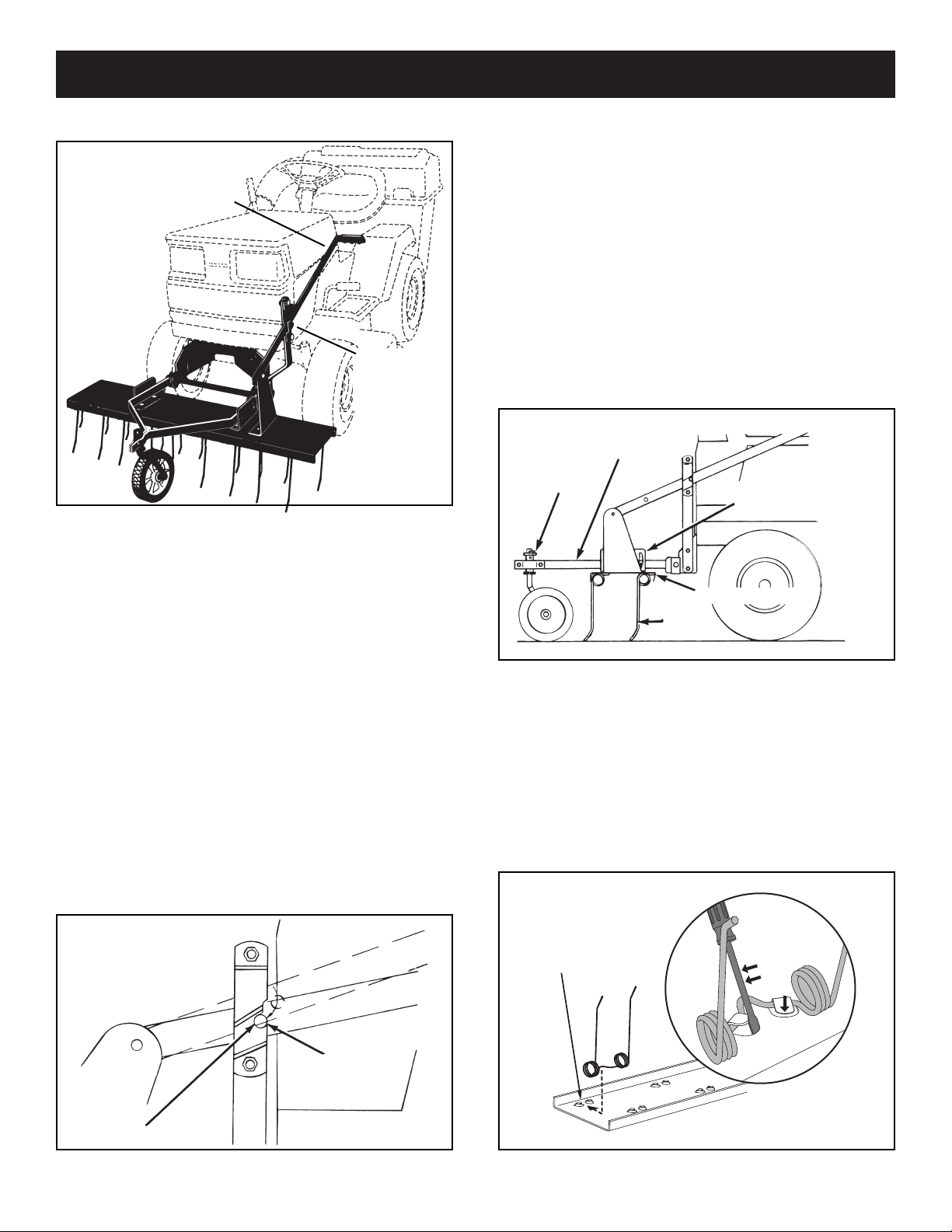
TO REMOVE DETHATCHER FROM TRACTOR
(Refer to gure 17).
• Lower dethatcher to ground.
• Remove 3/32" (small) hairpin cotter and 3/8" x 3/4"
clevis pin from lift handle. Remove handle from
handle lift bracket.
• Slide lift handle out between lift handle arm and
handle lock bracket.
FIGURE 17
(Refer to gure 18).
• Remove the two outside (large) 1/8" hairpin cotters
from mounting shaft and slide keeper plates off ends
of mounting shaft.
• Lift dethatcher from hitch bracket slots.
• Reassemble hairpin cotters and keeper plates to
mounting shaft for storage.
FIGURE 18
9
Page 10
OPERATION / SERVICE / ADJUSTMENTS
POCKET
SCREW
DRIVER
AXLE
BUSHING
MOUNTING
ARMS
GROUND
TINE SHIELD
TINES
ANGLE BRACKETS
NOTCH
STUD
KNOW YOUR DETHATCHER
LIFT HANDLE
LIFT HANDLE
Raises and lowers
dethatcher.
HANDLE LOCK BRACKET
Locks lift handle in raised
transport position.
HANDLE
LOCK
BRACKET
Leveling the dethatcher
• Move tractor with front mounted dethatcher onto a level
surface, such as a drive or garage oor.
• Lower dethatcher from transport position to rest on
level surface.
• Loosen carriage bolts through mounting arms and
angle brackets. (Refer to gure 3 on page 5.)
• Adjust tine shield until spring tines come in contact with
level surface, keeping front and back tines at same
height. Tighten mounting arm carriage bolts on top of
dethatcher shield to lock adjustment. See gure 20.
• If you need more adjustment, try moving the axle
bushing up or down between the mounting arms. Be
sure to retighten the bolts securing the bushing. See
gure 20.
HOW TO USE YOUR DETHATCHER
To raise dethatcher to transport position:
• Pull lift handle back so that stud in handle is pulled
past handle lock bracket. Push down and forward on
handle so that stud falls into notch on handle lock
bracket to lock in position. See gure 19.
To lower dethatcher to work position:
• Pull back and up on handle to release stud from notch
in handle lock bracket. Lower by holding up on handle
and pushing forward, allowing stud to pass through
lock bracket. See gure 19.
FIGURE 20
• To replace a spring tine:
a. Use a screw driver to pry the tabs up off of the
spring tine.
b. Remove old the spring tine from the tray.
c. Slide a new spring tine under the locking tabs.
Insert a screw driver and bend down the locking
tabs until the ends of the tabs are bent down
even with the surface of the tray. See gure 20.
FIGURE 19
FIGURE 21
10
Page 11

PARTS
A
2
3
5
5
7
8
9
10
11
12
14
15
15
16
16
17
17
17
17
17
17
18
18
18
18
26
22
23
27
29
28
23
23
24
15
25
A
1
4
4
25
25
6
13
15
15
19
20
21
25
40" TINE DETHATCHER MODEL 486.24312
REF
NO.
1 24874 1 Tine Shield
2 43783 10 Spring Tine
3 47633 2 Wire, Spring Alignment
4 23666 2 Angle Mount Bracket
5 24876 2 Mounting Arm
6 62601 1 Lift Handle Bracket
7 26043 1 Mounting Shaft
8 23673 1 Handle Lock Bracket
9 24043 1 Lift Handle Arm
10 44213 1 Wheel
11 44148 1 Axle
12 23668 1 Pivot Bushing
13 62600 1 Lift Handle
14 26168 1 Hitch Bracket
15 47810 14 Nylock Nut, 5/16-18
PART
NO.
QTY DESCRIPTION
REF
NO.
16 23676 2 Keeper Plate
17 43343 6 Hairpin Cotter, 1/8"
18 R19212113 4 Flat Washer, 5/8"
19 43943 1 Plastic Grip
20 44044 1 Clevis Pin, 3/8" x 3/4"
21 43055 1 Hairpin Cotter, 3/32"
22 43001 4 Hex Bolt, 3/8-16 x 1"
23 HA21362 10 Nylock Nut, 3/8-16
24 43063 2 Hex Bolt, 5/16-18 x 1"
25 44326 12 Carriage Bolt, 5/16-18 x 1"
26 43087 2 Hex Bolt, 3/8-16 x 1-1/4"
27 46838 4 Spacer, .8" x 1" x .5"
28 26044 1 Frame Mount Bracket
29 43069 4 Carriage Bolt, 3/8-16 x 1-1/2"
11
PART
40375 1 Owners Manual
NO.
QTY DESCRIPTION
Page 12

® Registered Trademark / TM Trademark /SM Service Mark of Sears Brands, LLC
® Marca Registrada /
TM
Marca de Fábrica / SM Marca de Servicio de Sears Brands, LLC
MC
Marque de commerce / MD Marque déposée de Sears Brands, LLC © Sears Brands, LLC
Get it fixed, at your home or ours!
Your Home
For repair – in your home – of all major brand appliances,
lawn and garden equipment, or heating and cooling systems,
no matter who made it, no matter who sold it!
For the replacement parts, accessories and
owner’s manuals that you need to do-it-yourself.
For Sears professional installation of home appliances
and items like garage door openers and water heaters.
1-800-4-MY-HOME
®
(1-800-469-4663)
Call anytime, day or night (U.S.A. and Canada)
www.sears.com www.sears.ca
Our Home
For repair of carry-in items like vacuums, lawn equipment,
and electronics, call or go on-line for the location of your nearest
Sears Parts & Repair Center.
1-800-488-1222
Call anytime, day or night (U.S.A. only)
www.sears.com
To purchase a protection agreement (U.S.A.)
or maintenance agreement (Canada) on a product serviced by Sears:
1-800-827-6655 (U.S.A.) 1-800-361-6665 (Canada)
Para pedir servicio de reparación
a domicilio, y para ordenar piezas:
1-888-SU-HOGAR
®
(1-888-784-6427)
Au Canada pour service en français:
1-800-LE-FOYER
MC
(1-800-533-6937)
www.sears.ca
 Loading...