

Page 1
Operator's Hanual
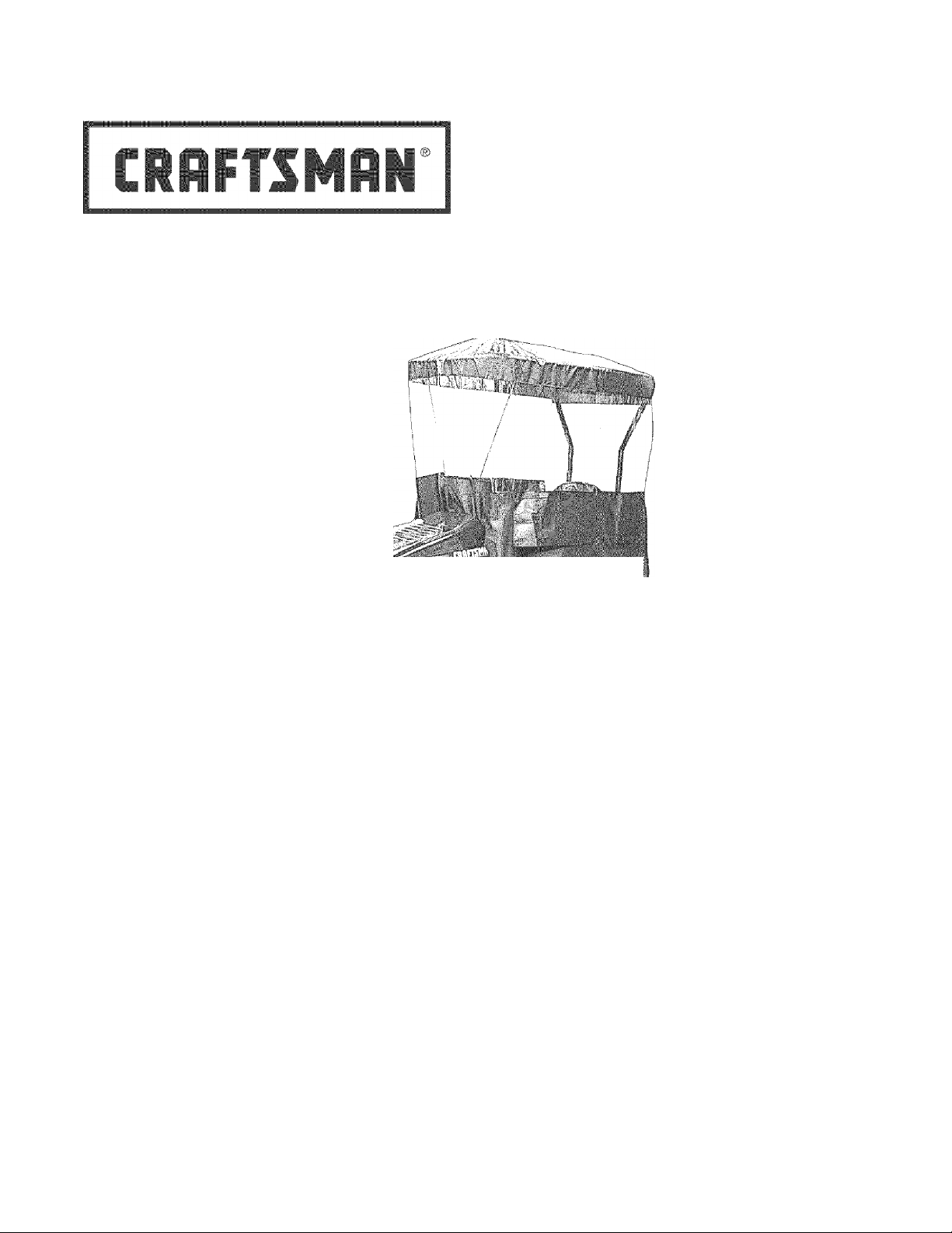
TRACTOR SNOW CAB
Model No. 486.24276
m
g“
«
CAUTION:
Before using this product, read
this manual and follow all Safety
Rules and Operating Instructions.
IMPORTANT: For Missing Parts or
Assembly Questions Call 1-866-576-8388
Sears, Roebuck and Co., Hoffman Estates, IL 60179 U.S.A.
WWW. sea rs. com/c rafts ma n
• Safety
• Assembly
• Operation
• yaintenance
• Parts
PRINTED IN U.S.A.
FORM NO, 49952 (11/05)
Page 2
1
TABLE OF CONTENT
j
SAFETY RULES..................................................................2
FULL SIZE HARDWARE CHART
CARTON CONTENTS.........................................................4
ASSEMBLY..........................................................................5
OPERATION........................................................................9
1-3 J
Any power equipment can cause injury if operated improperly or if the user does not understand how to operate the equipment.
Exercise caution at all times when using power equipment.
This cab provides foul weather protection only. It
does not provide protection against exhaust fumes,
collision, rollover or other accidents.
Read the snow cab and vehicle owner's manuals and
know how to operate your vehicle before using the
snow cab attachment.
Be sure there is adequate ventilation when using the
tractor and snow cab in confined areas.
.......................................
3
MAINTENANCE/STORAGE
REPAIR PARTS ILLUSTRATION.....................................10
REPAIR PARTS LIST.......................................................11
PARTS ORDERING/SERVICE
The snow cab will restrict your field of vision in some
directions. Use extra caution when operating your
tractor with the snow cab attached.
Watch out for low tree limbs or other overhead
obstructions that may not previously have interfered
with operation of the tractor. The extra height of
the snow cab may cause these objects to become
obstacles.
Check the area of operation thoroughly before using
the tractor.
...............................................
............................
Back Page
9
Look for this symbol to point out important safety precautions. It means — Attention!! Become
A
alert!! Your safety is in¥olved.
L
ONE YEAR FULL WARRANTY
When operated and maintained according to the instructions supplied with it, if this Tractor Snow Cab fails due to a defect in
material or workmanship within one year from the date of purchase, calf 1-800-4-MY-HOME© to arrange for free repair (or
replacement if repair proves impossible).
If this product is used for commercial or rental purposes, this warranty applies for only 90 days from the date of purchase.
This warranty gives you specific legal rights, and you may also have other rights which vary from state to state.
Sears, Roebuck and Co., D817WA, Hoffman Estates, IL 60179
The model number and serial numbers will be found on a
decal attached to the base assembly.
You should record both the serial number and the date of
purchase and keep in a safe place for future reference.
MODEL NUMBER: 486.24276
SERIAL NUMBER:
DATE OF PURCHASE:
_______________
_____
Page 3
1
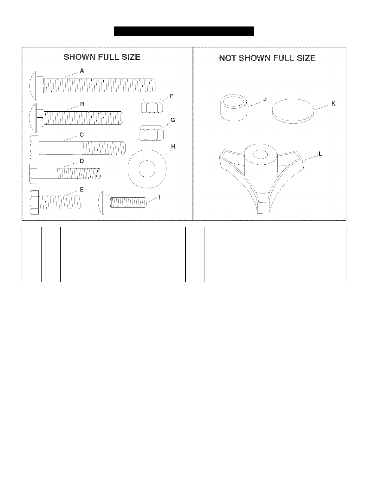
HARDWARE PACKAGE CONTENTS
j
REF. QTY. DESCRIPTION REF. QTY. DESCRIPTION
A 4
B 6
C 1 Hex Bolt, 5/16“ X 2"
D 4 Hex Bolt, 1/4 X M/2"
E 2 Hex Bolt, 5/16 X 1"
F 5
Carriage Bolt, 5/16" x 2-3/4“
Carriage Bolt, 5/16 x 2"
Nyiock Nut, 1/4"
G 5 Nyiock Nut, 5/16"
H 4 Flat Washer, 5/16"
1 1 Carriage Bolt, 1/4x1"
J 4 Spacer
K 4 Adhesive Pad
L 2
Plastic Knob
Page 4
1
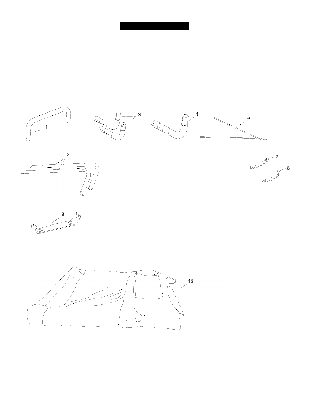
CARTON CONTENT
j
1. Upper base tube
2. Top Tubes (2)
3. Base Leg Tubes (2)
4. Base Leg Tube (Flattened)
5. Front Brace Rod
6. Upright Tubes (2)
7. Right Support Bracket
8. Left Support Bracket
9. Base Bracket
10. Left Base Bracket
11. Right Base Bracket (stamped with R)
12. U-Tube
13. Vinyl Canopy
14. Support Rods (3)
Tfi
-
10
11
12
f
.
ITH)
14
Page 5

1
ASSEMBL
j
TOOLS REQUIRED FOR ASSEMBLY
(2) 7/16" Wrenches
(2) 1/2" Wrench
(1) 1/2" or 9/16" Socket Wrench
REMOVAL OF PARTS FROM CARTON
• Remove ail parts and hardware packages from the
carton. Lay out parts and hardware and identify using
the illustrations on pages 3 and 4.
MOTE: Not all of the supplied parts and hardware will be
needed for one particular tractor. Unneeded items may be
discarded after assembly has been completed.
MOTE: Right hand (RH) and left hand (LH) are
determined from the operator's position while seated on
the tractor.
CAUTION: Make sure tractor seat raises
and lowers freely after attaching Snow
Cab. The tractor's operator presence safety
switch will not operate if seat is stuck down.
INSTRUCTIONS FOR TRACTORS WITH
SINGLE SUSPENSION BRACKET
STEP 2: (SEE FIGURE 2)
• The four holes in the base bracket are unequal in
height. Place the base bracket on a flat surface with
the holes that are higher facing away from you.
• Attach the right side of the base bracket to the middle
two holes in the flattened base teg tube using two
5/16" X 2" carriage bolts (B) and 5/16“ nylock nuts (G).
Make only finger tight.
• Attach the left side of the base bracket to the fourth
and fifth holes in one of the base leg tubes using two
5/16" X 2" carriage bolts (B) and 5/16" nylock nuts (G).
Make only finger tight.
• Attach the long end of the right support bracket to the
outside of the flattened end of the right base teg tube
using a 1/4" x T carriage bolt (I) and 1/4" nylock nut
(F). Make only finger tight
• Attach the left support bracket to the outside of the left
base teg tube using one 5/16" x 2" hex bolt (C) and
5/16" nylock nut (G). Make only finger tight.
STEP 1: (SEE FIGURE 1)
• Look under the front of your tractor. If there is a single
mower deck suspension bracket located underneath
the middle of the front axle, continue on to step 2. If
your tractor does not have a mower deck suspension
bracket underneath the middle of the front axle, skip
to step 5 on page 6 for tractors with dual suspension
brackets.
Page 6

STEPS: (SEE FIGURES)
• Insert the ends of the base leg tubes into the upper
base tube.
STEP 4: (SEE FIGURE 4)
• Raise the tractor seat and remove the seat springs and
the four bolts from the rear fender using a 1/2" socket.
• Place the base teg tubes onto the rear fender. Attach
the front support brackets to the front holes in the
fender reusing the bolts that were removed. If seat
springs were mounted to front holes, see note below.
Do not tighten completely.
• Attach the base bracket and the seat springs to the
rear holes in the fender using the new 5/16" x 1" bolts
(E) and 5/16" flat washers (H) supplied with the Snow
Cab. If seat springs were mounted to front holes, see
note below. Do not tighten completely.
• Tighten the nuts and bolts that fasten the base ieg
tubes to the base bracket and front support brackets.
• Center the base leg tubes on the rear fender and then
tighten, using moderate force, the bolts fastening
the base bracket and the front support brackets to
the fender. Overtightening the bolts may damage the
threaded holes in the fender.
• PROCEED TO STEP 8 ON PAGE 7
INSTRUCTIONS FOR TRACTORS WITH DUAL
SUSPENSION BRACKETS
STEP 5: (SEE FIGURE 5)
• Attach the right base bracket to the front holes of a
base leg tube that does not have a flattened end,
using two 5/16" X 2-3/4" carriage bolts (A), two
spacers (J) and two 5/16" nyiock nuts (G). Make onfy
finger tight. Repeat for the left base bracket.
STEPS: (SEE FIGURE 6)
• Insert the ends of the base leg tubes into the upper
base tube.
NOTE; If seat springs were mounted to front holes, use
5/16" X 1" bolts (E) and 5/16" flat washers (H) to attach
seat springs and front support brackets to front holes.
Use original bolts to attach base bracket to rear holes.
Page 7

STEP 7: (SEE FIGURE 7)
• Raise the tractor seat and remove the springs and
bolts from the rear fender using a 1/2“ socket for GT
tractors or a 9/16" socket for LT tractors.
• Place the base tube assembly onto the rear fender.
Align the front or rear slot in the base brackets with
the spring mounting holes. Check for clearance with
the seat lowered and the rear bagger (optional)
attached. If needed, reposition the base brackets to a
different set of holes in the base tubes.
• If the base leg tubes rub against the fender, attach the
adhesive pads (K) to the bottom of the base leg tubes.
• Attach the seat springs and the base brackets to the
rear fender using the spring bolts that you removed.
On GT tractors, if the spring bolts were less than 1"
long, use the 5/16” x T' bolts (E) and 5/16" washers
(H) supplied with the Snow Cab. Align the base leg
tubes on the rear fender. Use a 1/2" socket (GT) or
a 9/16" socket (LT) to tighten the seat spring bolts
using moderate force. Do not overtighten. Next,
tighten the bolts fastening the base leg tubes to the
base brackets.
COMPLETING ASSEMBLY ^ ALL TRACTORS
STEPS: (SEE FIGURE 8)
• Assemble the upright tubes to the base assembly
using a 5/16-18 x 2“ carriage bolt (B), 5/16" flat
washer (H) and plastic knob (L) for each tube.
NOTE; If holes do not align, loosen bolts attaching base
tubes to mounting bracket.
STEP 9: (SEE FIGURE 9)
• Assemble the top tubes to the upright tubes using
two 1/4" X 1-1/2" hex bolts (D) (outside) and two 1/4"
nylock nuts (F) (inside). Do not tighten yet.
• Fit the front U-tube onto the top tubes. Fasten the
tubes together using two 1/4" x 1-1/2" hex bolts
(D) (outside) and two 1/4" nylock nuts (F) (inside).
Tighten all loose bolts and nuts.
• Fit the three support rods into the holes in the top
tubes, with the rods arching upward. Do not over
bend the rods when installing.
Page 8

STEP 10: (SEE FIGURE 10)
• Raise the tractor's hood.
• Insert the ends of the front brace rod into the inner set
of holes in the U-tube and rest the bottom of the brace
rod on the dash panel. If the brace rod is too long to
rest on the dash panel, you can shorten the overall
length of the rod by inserting the upper ends of the
rod into one of the wider spaced sets of holes.
STEP 11: (SEE FIGURE 11)
• With the tractor's hood still raised, place the snow cab
canopy onto the tubing frame and drape the front flap
down in front of the tractor's dash panel. Lower the
hood, trapping the front flap under the hood. Secure
the sides of the canopy by fastening the elastic hooks
to the bottom edge of the footrest and fender. Tie the
straps at back of canopy to the upright tubes. Any
levers or handles on snow throwers or snow blades
should be located outside of the cab.
Page 9

OPERATIO
1
Read this owner’s manual and safety rules before operating your tractor with the snow cab.
j
A
A
A
1
CAUTION: This snow cab does not
provide protection against exhaust fumes,
collision, rollover or other accidents.
CAUTION: Watch out for low tree limbs
and other overhead objects which may
interfere with the snow cab.
CAUTION: Never transport the tractor in
an open truck or open trailer while the snow
cab is attached.
MAINTENANCE/STORAG
Check the area of operation thoroughly before using
the tractor with the snow cab. The added height of the
snow cab and a reduced field of vision require extra
caution during operation.
Remove the upper snow cab frame and canopy before
you transport the tractor in an open truck or open
trailer.
j
CUSTOMER RESPONSIBILITIES
• Read and follow the maintenance schedule and the maintenance procedures listed in this section.
MAINTENANCE SCHEDULE
Fill in dates as you
complete regular service. Service Dates
Check for loose fasteners X
Cleaning X X
CHECK FOR LOOSE FASTENERS
• Before each use make a thorough visual check of
the snow cab for any bolts and nuts which may have
loosened. Retighten any loose bolts and nuts.
CLEANING
• Wipe loose dirt and debris from the vinyl canopy after
each use. The vinyl canopy can be washed using mild
liquid soap and water.
STORAGE
• Clean the vinyl canopy thoroughly with mild liquid
soap and water. Alow to dry before storing.
• Store the snow cab in a clean, dry area away from
direct sun tight.
Page 10

1
PART
j
REPAIR PARTS FOR MODEL 486.24276 SNOW CAB
13
Page 11

REPAIR PARTS FOR MODEL 486.24276 SNOW CAB
REF.
NO.
1 49242 1
2 25014 2
3 25013 2
4 25012 1 U-Tube 18 25302 1
5 25015 3 Support Rod 19 25303 1 Left Base Bracket
6 48738 1 Vinyl Canopy 20 25835 1 Right Support Bracket
7 23658 4
8 43720 2
9 44977 6
10 43081 4 Flat Washer, 5/16" 24 44180 1 Hex Bolt, 5/16-18x2"
11 43648 4 Hex Bolt, 1/4-20 X 1-1/2" 25 43176 1
12 47189 5 NylockNut, 1/4-20 26 47810 5 NylockNut, 5/16-18
13 48661 4
14 43063 2 Hex Bolt, 5/16-18 X 1"
PART
NO.
QTY. DESCRIPTION REF.
NO.
Top Base leg tube
Upright Tube
Top Tube
Spacer
Plastic Knob
Carriage Bolt, 5/16-18 x 2"
Adhesive Pad
15 25795 1 Front Brace Rod
16 49325 2
17 40003 1
21 25794 1 Left Support Bracket
22 25793 1
23 46594 4
PART
NO.
49952 1
QTY. DESCRIPTION
Base Leg Tube
Base Leg Tube, Flattened
Right Base Bracket
Base Bracket
Carriage Bolt, 5/16-18 x 2-3/4"
Carriage Bolt, 1/4-20 x 1"
Owner's Manual
11
Page 12

Get it fixed, at your home or ours!
Your Home
For repair-in your home-of all major brand appliances,
lawn and garden equipment, or heating and cooling systems,
no matter who made It, no matter who sold it!
For the replacement parts, accessories and
owner’s manuals that you need to do-it-yourself.
For Sears professional installation of home appliances
and items like garage door openers and water heaters.
1-800-4-MY-HOME® (1-800-469-4663)
Call anytime, day or night (U.S.A. and Canada)
www.sears.com www.sears.ca
Our Home
For repair of carry-in items like vacuums, lawn equipment,
and electronics, call or go on-line for the location of your nearest
Sears Parts & Repair Center.
1-800-488-1222
Call anytime, day or night (U.S.A. only)
www.sears.com
To purchase a protection agreement (U.S.A.)
or maintenance agreement (Canada) on a product serviced by Sears:
1 -800-827-6655 (u s A) 1 -800-361 -6665 (Canada)
Para pedir servicio de reparación
a domicilio, y para ordenar piezas:
1-888-SU-HOGAR®
(1-888-784-6427)
Au Canada pour service en français:
1-800-LE-FOYER“"
(1-800-533-6937)
www.sears.ca
® Registered Trademark / ™ Trademark / Service Mark of Sears Brands, LLC
® Marca Registrada / ™ Marca de Fábrica / Marca de Servicio de Sears Brands, LLC
Marque de commerce / Marque déposée de Sears Brands, LLC
© Sears Brands, LLC
 Loading...