

Craftsman 486240320 Owner’s Manual
SEAIRS
32" CRAFTSMAN LAWNSWEEPER
CAUTION:
Read Rules for
Safe Operation
and Instructions
Carefully
L
® Assembly
Operation
® Maintenance
® Repair Parts
Sears, Roebuck and Co, Chicago, Ill 60684 USA
PRINTED IN U S A
RULES FOR SAFE OPERATION
The following safety precautions are suggested This
lawn sweeper is designed, engineered and tested to
offer reasonably safe and effective service,
provided it is operated in strict accordance with these
instructions Failure to do so may result in personal
injury. Always observe the rules for safe operation..
1. Do not allow anyone to operate the sweeper
without proper instructions°
2. Do not permit children to operate sweeper.
3. Do not push or tow sweeper too close to a fire,
because the hopper and brush will burn,
4, Do not attempt to remove wire or string
wrapped around brush while brush is rotating,
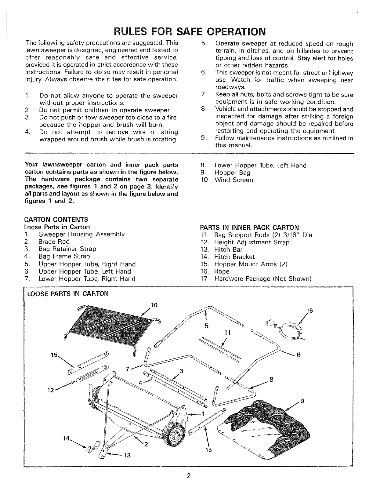
Your lawnsweeper carton and inner pack parts
carton contains parts as shown in the figure below.
The hardware package contains two separate
packages, see figures 1 and 2 on page 3. Identify
all parts and layout as shown in the figure below and
figures 1 and 2.
CARTON CONTENTS
Loose Parts in Carton
t,
Sweeper Housing Assembly
Brace Rod
2.
3.
Bag Retainer Strap
4,
Bag Frame Strap
5°
Upper Hopper Tube, Right Hand
6,
Upper Hopper Tube, Left Hand
7,
Lower Hopper Tube, Right Hand
5. Operate sweeper at reduced speed on rough
terrain, in ditches, and on hillsides to prevent
tipping and toss of control Stay alert for holes
or other hidden hazards..
6. This sweeper is not meant for street or highway
use.. Watch for traffic when sweeping near
roadways,
7. Keep all nuts, bolts and screws tight to be sure
equipment is in safe working condition.
8 Vehicle and attachments should be stopped and
inspected for damage after striking a foreign
object and damage should be repaired before
restarting and operating the equipment
9 Follow maintenance instructions as outlined in
this manual.,
8, Lower Hopper Tube, Left Hand
9, Hopper Bag
10 Wind Screen
PARTS IN INNER PACK CARTON:
!1, Bag Support Rods (2) 3/16" Dia,
12. Height Adjustment Strap
13. Hitch Bar
14, Hitch Bracket
15 Hopper Mount Arms (2)
16. Rope
17 Hardware Package (Not Shown)
LOOSE PARTS IN CARTON
16
5
11
t5
13
2
_<_£_-_-y @ @-_--W _l_r _-'Ac
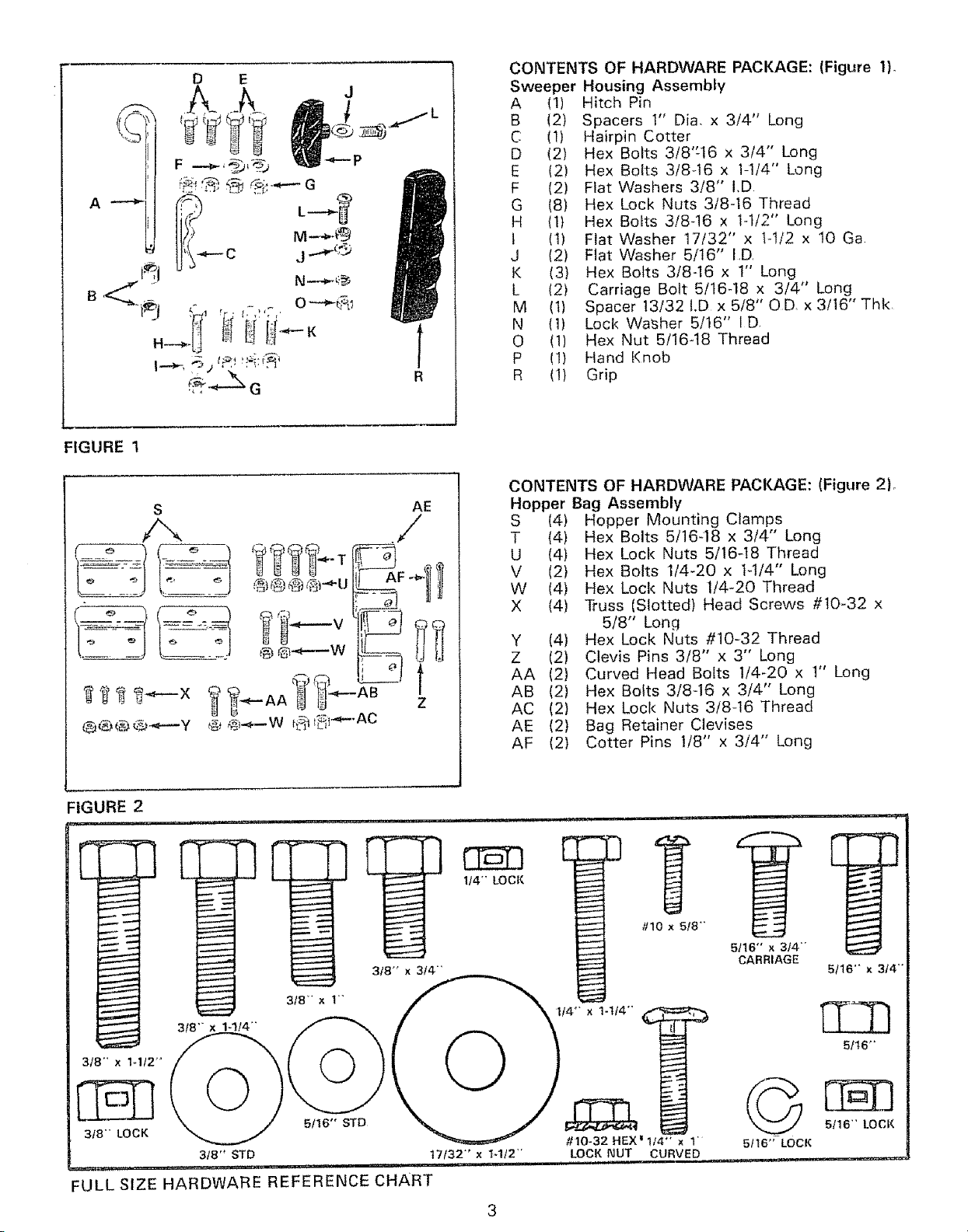
CONTENTS OF HARDWARE PACKAGE: (Figure tL
Sweeper Housing AssembLy
A (I)
B (2)
C (1)
D (2)
E (2)
F (2)
G (8)
H (t)
t (1)
J (2)
K (3)
L (2)
M (t)
N (1)
0 (1)
P (1)
R (1)
Hitch Pin
Spacers 1" Dia, x 3/4" Long
Hairpin Cotter
Hex Bolts 3/8"16 x 3/4" Long
Hex Bolts 3/8q6 x 1-1/4" Long
Flat Washers 3/8" I,D
Hex Lock Nuts 3/8-16 Thread
Hex Bolts 3/8-16 x 1-1/2" Long
Flat Washer 17/32" x t-t/2 x t0 Ga
Flat Washer 5/16" I,D,
Hex Bolts 3/8-16 x t" Long
Carriage Bolt 5/16-18 x 3/4" Long
Spacer 13/32 I.D x 5/8" OD, x 3/16" Thk
Loci< Washer 5/16" I D
Hex Nut 5/16-t8 Thread
Hand Knob
Grip
CONTENTS OF HARDWARE PACKAGE: (Figure 2L
Hopper Bag Assembly
S (4) Hopper Mounting Clamps
T (4) Hex Bolts 5/16-18 x 3/4" Long
U {4) Hex Loci{ Nuts 5/16-t8 Thread
V (2) Hex Bolts I/4-20 x H/4" Long
W (4) Hex Lock Nuts 1/4-20 Thread
X (4) Truss (Slotted) Head Screws #10-32 x
5/8" Long
Y (4) Hex Lock Nuts #10-32 Thread
Z (2) Clevis Pins 3/8" x 3" Long
AA (2) Curved Head Bolts 1/4-20 x 1" Long
AB (2) Hex Bolts 3/8-16 x 3/4" Long
AC (2) Hex Lock Nuts 3/8-16 Thread
AE (2) Bag Retainer Clevises
AF (2) Cotter Pins 1/8" x 3/4" Long
:tGURE 2
lU.llUl, iii
[ F
318- x 1'"
3!8- x 1-114"
3/8- x 1-1/2-
318'" LOCK
3/8" STD t7/32"' x t_1/2"'
.......... i, .,, , H,,, ,,,,i,,i,H,,u , i,u
:ULL SIZE HARDWARE REFERENCE CHART
5/16" STD
1/4- LOCI{
I #10 x5_8 "'
_ -
#10-32 HEX' 1/4" × 1
LOCI{ NUT
i ,,,, ,.
CURVED
5/16"" × 314-
CARRIAGE
©
5116" LOCK
r _
_r
i
/
/
5!16'" x 3/4-
5/16"
5116" LOCI{
ASSEMBLY 0NSTRUCTIONS
TOOLS REQUIRED
(1) Adjustable Wrench
(I) 3/8" Open End or Box Wrench
(1) 7/16" Open End or Box Wrench
(1) 1/2" Open End or Box Wrench
(1) 9/t6" Open End or Box Wrench
(1) Standard Screwdriver
(t) Pair of Pliers
Refer to carton contents figure on page 2 and figure
I on page 3 for parts and hardware needed to
assemble sweeper housing,,
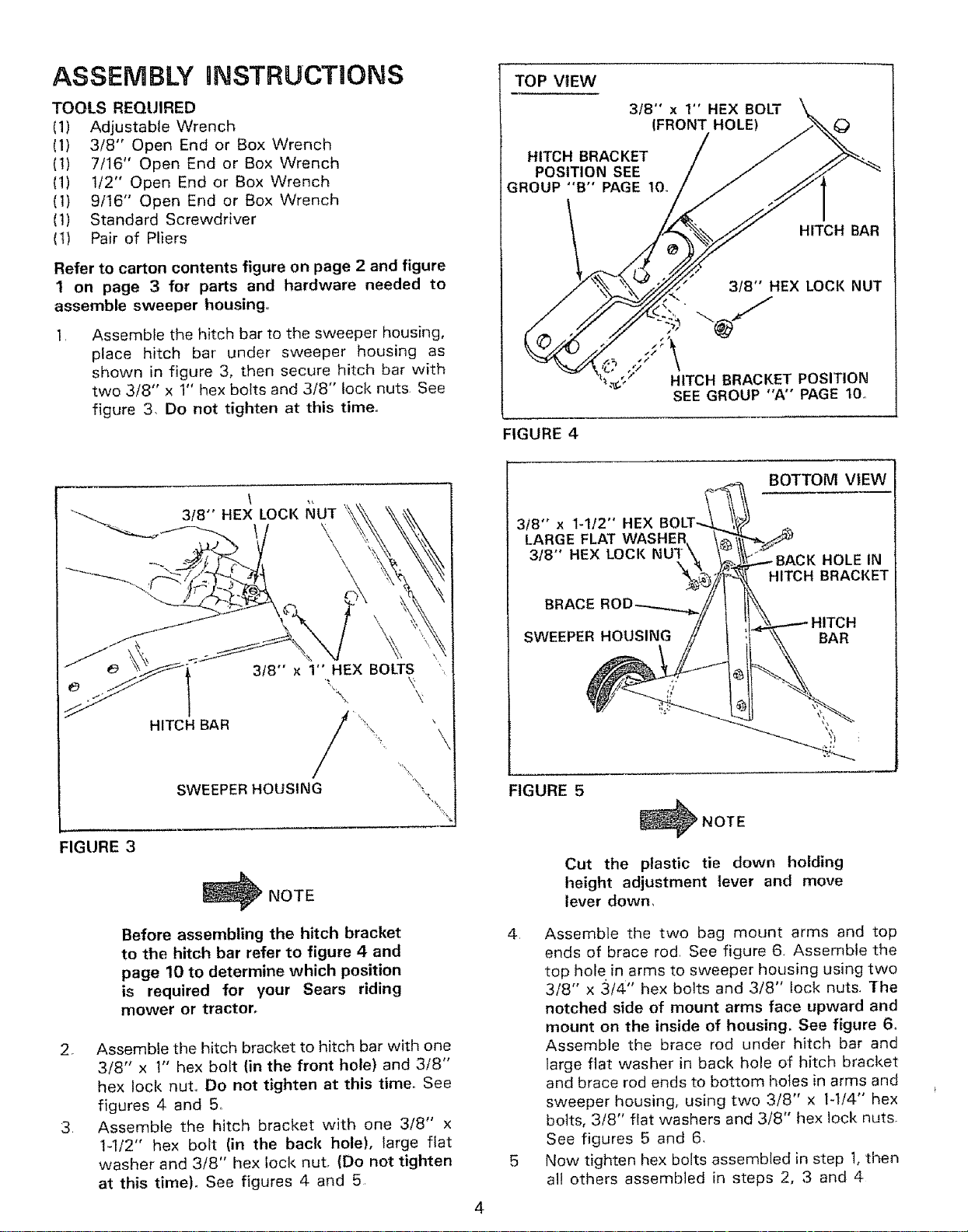
Assemble the hitch bar to the sweeper housing,
place hitch bar under sweeper housing as
shown in figure 3, then secure hitch bar with
two 3/8" x 1" hex bolts and 3/8" lock nuts. See
figure 3. Do not tighten at this time.
TOP VIEW
3/8" x 1" HEX BOLT
HITCH BRACKET
POSITION SEE
GROUP "B" PAGE 10,
FIGURE 4
3/8" x I-1/2" HEX
LARGE FLAT WASHER
3/8" HEX LOCK
BRACE
(FRONT HOLE)
HITCH BAR
3t8'" HEX LOC!( NUT
HITCH BRACKET POSITION
SEE GROUP "A'" PAGE 10.
BOTTOM VIEW
BACK HOLE IN
HITCH BRACKET
3/8" x 1" HEX BOLTS
HITCH BAR " '
SWEEPER HOUSING
_,_,
FIGURE 3
_NOTE
Before assembling the hitch bracket
to the hitch bar refer to figure 4 and
page 10 to determine which position
is required for your Sears riding
mower or tractor.
2o Assemble the hitch bracket to hitch bar with one
3/8" x 1" hex bolt (in the front hole) and 3/8"
hex lock nut,, Do not tighten at this time_ See
figures 4 and 5o
3 AssembJe the hitch bracket with one 3/8" x
1-1/2" hex bolt (in the back hole), large flat
washer and 3/8" hex lock nut, (Do not tighten
at this time), See figures 4 and 5,
SWEEPER HOUSING
FIGURE 5
_NOTE
Cut the plastic tie down holding
height adjustment lever and move
lever down,
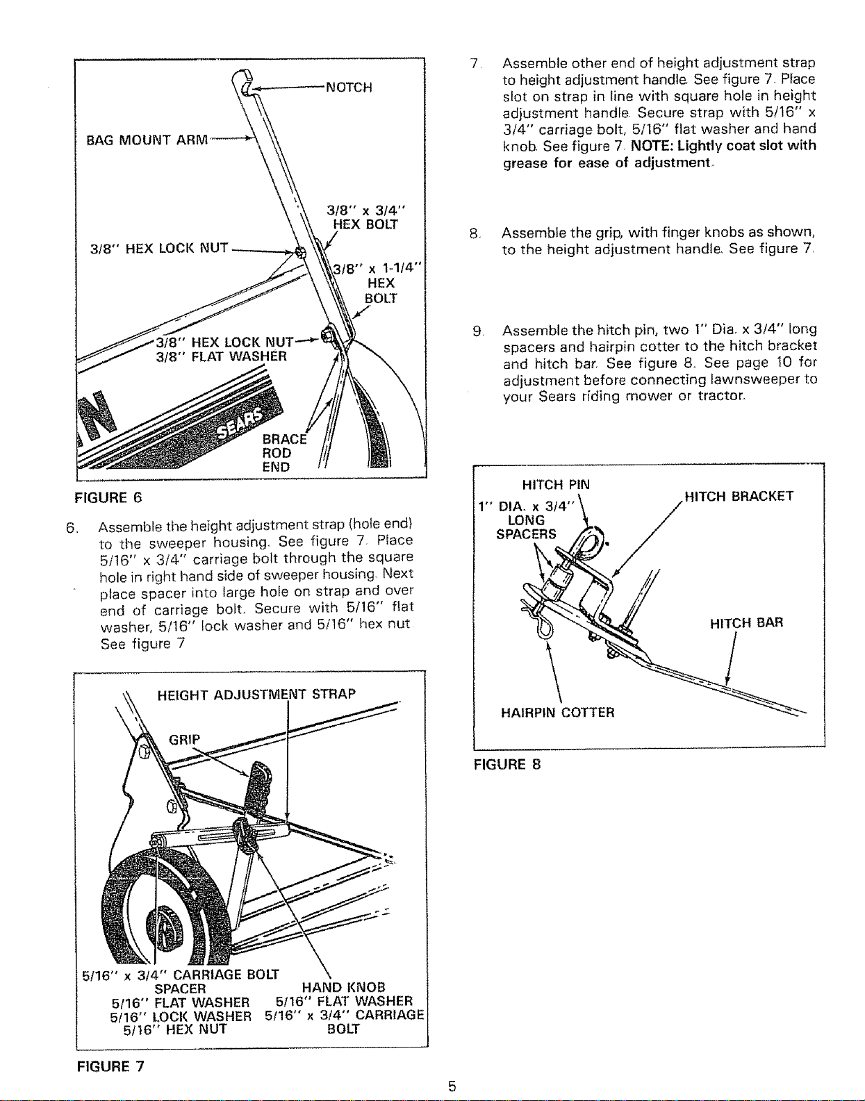
4 Assemble the two bag mount arms and top
ends of brace rod. See figure 6. Assemble the
top hole in arms to sweeper housing using two
3/8" x 3/4" hex bolts and 3/8" lock nuts, The
notched side of mount arms face upward and
mount on the inside of housing. See figure 6o
Assemble the brace rod under hitch bar and
large flat washer in back hole of hitch bracket
and brace rod ends to bottom holes in arms and
sweeper housing, using two 3/8" x 1-1/4" hex
bolts, 3/8" flat washers and 3/8" hex loci< nuts.
See figures 5 and 6,
5 Now tighten hex bolts assemb(ed in step 1,then
all others assembled in steps 2, 3 and 4
4
BAR
BAG MOUNT
FIGURE 6
\
BRACE
ROD
END
318'" x 314"
HEX BOLT
x 1-1t4"
HEX
BOLT
,
Assemble other end of height adjustment strap
to height adjustment handle See figure 7. Place
slot on strap in line with square hole in height
ad}ustment handle Secure strap with 5/16" x
3/4" carriage bolt, 5/16" flat washer and hand
knob See figure 7. NOTE: Lightly coat slot with
grease for ease of adjustment.
,
Assemble the grip, with finger knobs as shown,
to the height adjustment handle, See figure 7,
,
Assemble the hitch pin, two 1" Diao x 3/4" long
spacers and hairpin cotter to the hitch bracket
and hitch bar. See figure 8 See page 10 for
adjustment before connecting lawnsweeper to
your Sears riding mower or tractor.
HITCH PIN
,, Assemble the height adjustment strap (hole end)
to the sweeper housing. See figure 7 Place
5/16" x 3/4" carriage bolt through the square
hole in right hand side of sweeper housing. Next
peace spacer into large hole on strap and over
end of carriage bolt, Secure with 5/16" flat
washer, 5/t6" !ock washer and 5/16" hex nut
See figure 7
HEIGHT ADJUSTMENT STRAP
_RIP
1" DIA.LoNGX3/4 ''_ ///HITCH BRACKET
' ) ,g
AR
HAIRPIN_COTTEI. _-"_."_-...
FIGURE 8
5116" x 3t4" CARRIAGE BOLT
SPACER HAND KNOB
5/16" FLAT WASHER 5116" FLAT WASHER
5/16" LOCI( WASHER 5/16" x 3/4" CARRIAGE
5f16" HEX NUT BOLT
FIGURE 7
 Loading...