

Craftsman 48181 Operator's Manual
Operator’s Manual
3 Piece Floor Jack Set
Model 48181
CUSTOMER HELP LINE
Parts and Questions
1-888-332-6419
8:00 AM - 4:45 PM Central Time
Monday- Friday
Creeper
Jack Stands
WARNING: Before using this product,
read this Operator’s Manual and follow
all its Safety Rules and Operating
Instructions.
Floor Jack
• Safety
• Operation
• Maintenance
Sears Brands Management Corporation, Homan Estates, IL 60179 U.S.A.
www.craftsman.com
ASME PASE 2014 Compliant
Printed in China
Jack
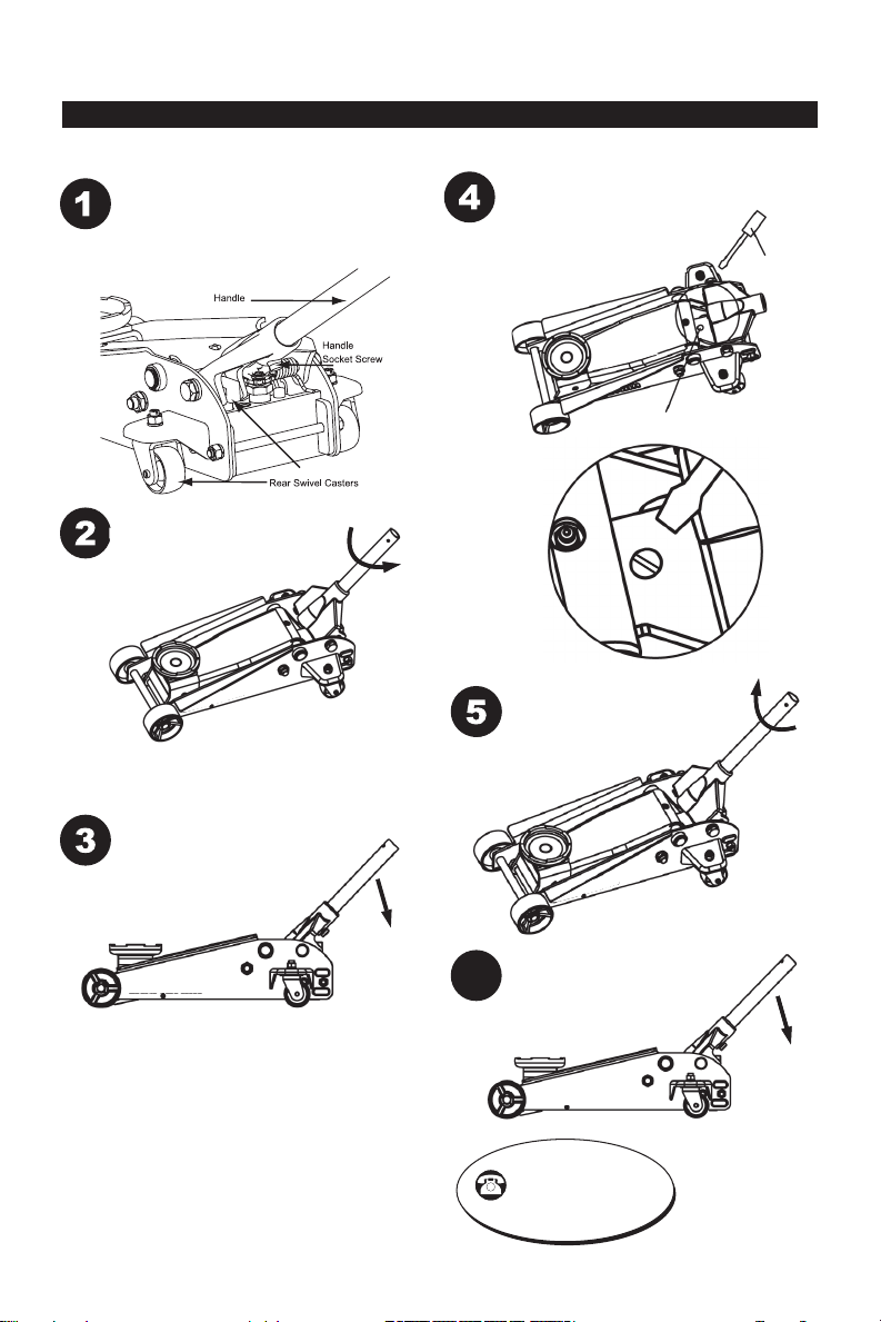
AIR PURGE PROCEDURE
IMPORTANT: BEFORE FIRST USE, perform the following Air Purge Procedure to remove any air that may
have been introduced into the hydraulic system as a result of product shipment and handling.
Insert Handle
See “ ASSEMBLY” on page 4 to
assemble handle. Loosen handle
socket screw. Insert end of handle
into handle socket. Tighten screw.
.
Pump Plunger
Turn Handle
Counterclockwise
Turn handle counterclockwise
two full turns to fully open
release valve.
Purge Air
With a at blade screwdriver,
loosen the oil ll screw
about halfway up to release
trapped air from
the system. Tighten the
screw back down.
Oil Fill Screw
Screwdriver
Rapidly Pump
Rapidly pump the handle 6 - 8
times. Leave handle in down
position to expose oil ll screw.
Turn Handle Clockwise
Turn the handle clockwise until it
stops.
READY TO USE
Jack is now ready for use. Check
6
for proper pump action.
CUSTOMER HELP LINE
Parts and Questions
1-888-332-6419
8:00 AM - 4:45 PM Central Time
Monday- Friday
2
NOTE: Repeat this
Air Purge Procedure
whenever the jack
displays reduced
lifting performance.

SAFETY INSTRUCTIONS
Read Operating Instructions
Study, understand and follow all instructions in
this manual before operating the jack. Failure
to heed these warnings may result in loss of
load, damage to the jack and/or jack failure
resulting in personal injury or property damage.
Position the Jack
This jack is designed only for lifting part of
the total vehicle. Position the jack to only lift
on the areas of the vehicle specied by the
vehicle manufacturer.
Use Support Stands
After lifting the vehicle always support the
load with appropriately rated vehicle support
stands before working on the vehicle.
Do Not Overload Jack
Do not overload this jack beyond its rated
capacity. Overloading this jack beyond its
rated capacity can cause damage to or failure
of the jack.
Use on Hard Level Surface
This jack is designed only for use on hard level
surfaces capable of sustaining the load. Use
on other than hard level surfaces can result in
jack instability and possible loss of load.
Center Load on Jack Saddle
Center load on jack saddle before lifting
vehicle. O-center loads and loads lifted
when the jack is not level can cause loss
of load or damage to the jack. Only use on
vehicles whose lift points t well with saddle
of this jack.
Do Not Use Jack as Dolly
Do not move or dolly the vehicle while it is on
the jack. Do not use this jack to lift or move
a building, mobile home or travel trailer of
any type.
KEEP HANDS AND FEET CLEAR OF
THE JACK HINGE MECHANISM AND
GROUND CONTACT AREA WHEN
LOWERING THE LOAD!
CRAFTSMAN LIMITED WARRANTY
CRAFTSMAN LIMITED WARRANTY
FOR ONE YEAR from the date of sale this
product is warranty against defects in material
or workmanship. WITH PROOF OF SALE
a defective product will be replaced free of
charge.
For warranty coverage details to obtain
free replacement, visit the web page: www.
craftsman.com/warranty
This warranty applies for only 90 days from
the date of sale if this product is ever used
while providing commercial services or if
rented to another person.
This warranty gives you specic legal rights,
and you may also have other rights which vary
from state to state.
Sears Brands Management Corporation,
Homan Estates, IL 60179
DESCRIPTION
This jack features a 6,000 lbs. maximum load
capacity. Lifting range for this jack is 5-1/2
inches to 18-1/2 inches. Jack features an
overload valve bypass system to prevent jack
damage and user injury.
Specications
Compact design allows use in conned spaces
Maximum load capacity........3 tons (6,000 lbs.)
Service jack lift range.....5-1/2 to 18-1/2 inches
Weight....................................................75 lbs.
WARNING: This product contains chemicals
known to the state of California to cause
cancer and birth defects or other reproductive
harm. www.P65Warnings.ca.gov
THIS IS A LIFTING DEVICE ONLY!
DO NOT work on vehicle supported by jack.
Immediately after lifting, support load with
appropriately rated vehicle support stands before
working on vehicle.
3
Pump Plunger
Oil Fill
Screw
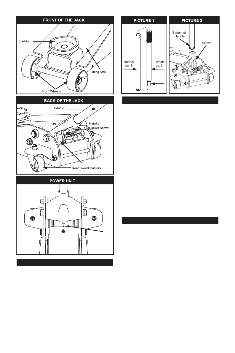
PREPARATION
Preparation
After rst removing from shipping box
• Carefully remove the retaining clip from the
back of the service jack.
CAUTION: The socket will tend to spring
upward when the clip is removed. To prevent
possible injury, place one hand on top of
socket to control its upward motion when
removing clip with other hand.
Pin
ASSEMBLY
Assembly
Handle Assembly
• Refer to Picture 1 when performing this step.
Align Quick Disconnect pushpin in upper
handle piece with attachment hole in lower
handle piece. Push upper piece into lower
piece until pushpin pops through hole.
• Suciently loosen the Handle Socket Screw
to insert the assembled handle (Picture 2).
• Line up the square shaped hole located at
the bottom of the handle over the square
bolt inside the Handle Socket.
• Lower the handle onto the bolt. Secure the
handle in place by tightening the Handle
Socket Screw until the handle stops rotating.
NOTICE: ONLY use the handle provided
with this jack. Handle is specially designed
to properly t into handle socket and engage
release valve.
FEATURES & OPERATION
Operation
Raising the Jack
• Place vehicle in park, with emergency brake
on and wheels securely chocked to ensure
lifting stability.
• Refer to the vehicle manufacturer owner’s
manual to locate the approved vehicle lifting
points.
• Position the jack so that the saddle will rmly
contact the vehicle lifting point.
• Close the release valve by turning the
handle clockwise until it stops.
• Pump jack handle until saddle nears contact
with vehicle lifting point. Check to see that
the saddle is centered and will contact lifting
point rmly.
4
 Loading...