

Craftsman 390307060 Owner’s Manual
!
SEARS
OWNER'S
MANUAL
ModelNo.
390.307060
CAUTION:
Read and Follow
All Safety Rulesand
Operating Instructions
Before FirstUse of
ThisProduct.
Save ThisManual For
FutureReference.
Sears, Roebuck and Co., Haffman Estates, IL 60179 U.S.A.
PRINTED IN USA Form No F642-9901 (Rev 4/19/04)
I:RRFTSMRN°
BATTERY OPERATED
BACKUP SUMP PUMP
• Safety Instructions
• Operation
• Installation
• Troubleshooting
• Repair Parts
CONTENTS
Introduction/Warranty ........................................................ 2
Safety ................................................................................... 2
Performance ........................................................................ 3
Charger Operation ............................................................... 3
Battery Requirements .......................................................... 4
Installation/Operation ...................................................... 4-5
Electrical ........................................................................... 5-6
Service/Troubleshooting .................................................. 6-7
Repair Parts.......................................................................... 7
INTRODUCTION
Please take a few minutes to read our instructions before in-
stalling your Backup Sump Pump. It wlg help to assure per-
fect installation and help you avoid needless service
expenses.
IMPORTANT SAFETY INSTRUC-
TIONS for BATTERY CHARGER
[AWARNING] Risk of electrical shock, fire, or explo-
sion. Read all instructions in owner's manual and on
charger, pump, and battery before using battery charger.
1. Unplug battery charger before attempting any cleaning.
2. Charge onlyrechargeable 12.volt lead-acid batteries.
3. Do not let charger get wet.
4. Use only attachments recommended or sold by battery
charger manufacturer.
5. When unplugging charger, grasp plug (not cord) to avoid
risk of damage to cord or plug.
6. Locate cord so that it cannot be stepped on, tripped over,
damaged, stretched, or flooded,
7. Do not modify cord or plug.
8. Do not attempt to service charger; it has no user-ser-
viceable parts. If charger is dropped, struck, or otherwise
damaged, replace the charger.
SAVE THESE INSTRUCTIONS
RULES FOR SAFE INSTALLATION AND OPERATION
Carefully read and follow all safety instructions in this
manual or on pump.
_This is the safety alert symbol. When you see this
symbol on your pump or in this manual, look for one of the
following signal words and be alert to the potential for per-
sonal injury!
DANGER warns about hazards that will cause
serious personal injury, death or major property damage if
ignored.
[AWARNING]WARN1NG warns about hazards that can
cause serious personal injury, death or major property dam-
age if ignored.
I_ CAUTION ]CAUTION warns about hazards that will or can
cause minor personal injuryor property damage if ignored.
The word NOTICE indicates special instructions which are
important but not related to hazards.
l.To avoid risk of serious bodily injury due to electrical
shock or burns and property damage due to flooding, read
the safety instructions carefully before installing pump.
IAWARNINGJBattery acid is corrosive. Do not spill on
skin, clothing, or battery charger. Wear eye and head
protection when working with battery. Connect and dis-
connect DC output termianls only after removing the
charger from the AC outlet. Never allow the DC terminals to
touch each other.
[_, WARNINGIHazardous voltage. Can cause severe or
fatal electrical shock. Do not plug in or unplug battery
charger while standing on a wet floor or in water. Be sure
one hand is free when plugging in or unplugging charger. If
basement floor is wet, disconnect power to basement be-
fore walking on floor.
p
1_, CAUTION ]Risk of flooding. Do not run pump dry. To
do so will damage seals and can cause leaking and property
damage.
2.Follow local and/or national plumbing and electrical
codes when installing the system. A ground fault circuit
interrupter (GFCI) is recommended for use on any elec-
trical appliance submerged in water.
3. Use this system only for backup sump pump duty in a res-
idential application. It is not designed as a primary sump
pump.
4. Do not lift pump by electrical cord.
_RNINGIRisk of electrical shock. Do not lift the
pump by the electrical cord; lift pump only by the discharge
pipe, lifting ring or handle on the pump. Lifting by the cord
can damage the cord.
5.Pump clear water only with this pump.
6. Pump is permanently lubricated at the factory. Do not try
to lubricate it!
7. Keep battery charger and battery box off of the floor
and in a dry, cool, well ventilated area.
NOTICE: If a Carbon Monoxide (CO) sensor is in-
stalled, it must be at least 15 feet away from battery
charger in order to avoid nuisance CO alarms. Please
refer to your CO detector's installation guidelines for
more information.
8. To avoid danger of fire or explosion, keep sparks and
flame (pilot fight) away from battery.
9. Maximum vertical pumping distance is 15 feet (4.6M).
10. Make sure sump is clear of debris. Debris can damage the
pump which can result in flooding.
i
GENERAL INFORMATION
The Battery Back-up Sump System is not a substitute for your
primary sump pump. It is designed to temporarily back up
your primary sump pump during a power outage or other
problem which prevents normal operation of the primary
pump. Do not use this system to pump flammable liquids or
chemicals. Pump clear water only with this pump.
Keep battery charger dry and protected from damage.
In an emergency (such as an extended pnwer outage)
which depletes the system's deep cycle marine battery, your
automobile battery may be temporarily substituted. Be sure
to replace the deep cycle marine battery as soon as possible.
Use of an automobile battery instead of a deep cycle marine
battery in this system will significantly reduce system per-
formance. Automobile batteries arc not designed for this
type of application.
NOTICE: This unit is not designed for applications involving
salt water or brine! Use with salt water or brine will void
warranty.
BATTERY BACKUP SYSTEM
INSTALLATION AND
OPERATION
NOTICE: Install this system during a time when the primary
pump will not be needed. Gather all supplies before start-
ing. Read all warnings and installation steps before you start.
NOTICE: Be prepared for water to leak from the coupling
or piping when disassembling or cutting the discharge pipe.
Protect system components, tools and supplies from getting
wet. Dry any work areas that get wet.
BASIC TOOLS AND
MATERIALS NEEDED
Sill>joint or large pliers
Tape measure
Socket wrench or 5/16" nut driver
Side cutters
Hacksaw (to cut PVC pipe)
Medium size pliers
Pencil
Teflon tape
PVC glue (solvent weld) and primer
Cloth towel
24M Deep Cycle Marine Battery
or a
27M Deep Cycle Marine Battery
LAWARNINGJ Personal injury and flood hazard. Do not
turn the pump on until all the fittings are glued and the glue
has dried. Loose fittings can explode off the pipes and cause
personal injury and flooding.
Remove Primary Pump From Sump Pit:
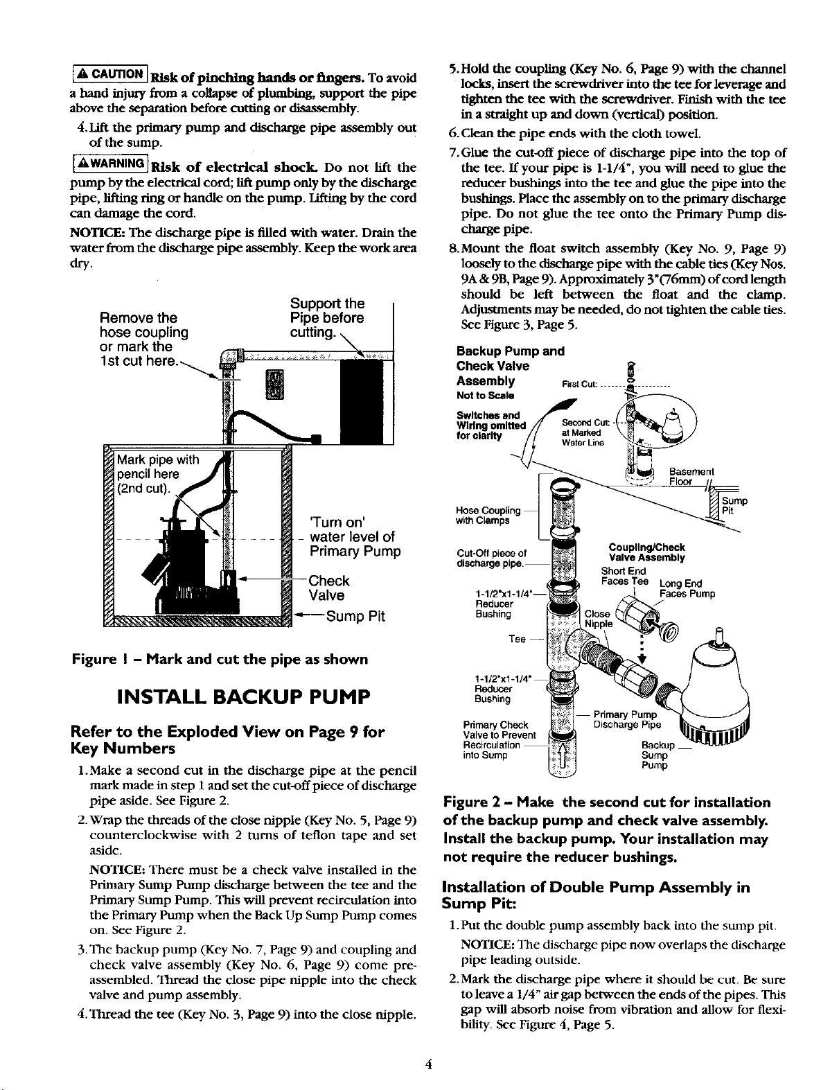
1.Locate the "on" water level of the primary sump pump.
Mark this location on the discharge pipe with a pencil.
See Figure 1.
2. Drain the sump and unplug the pump. The water level
must be pumped down as low as possible before going
on to the next step.
i
I& WARNINGJElectrical shock hazard. Shock can bum
or kill. Do not make contact with the remaining water in
the sump pit. Unplug the primary sump pump and any
accessories such as alarms before you continue. Failure
to follow this warning can result in personal injury or
death.
3. To separate the primary pump from the discharge pipe:
A. For applications with rubber couplings: remove the
coupling clamp with a nut driver, and be prepared for
water to spill out.
B. For applications without rnbber couplings: cut the
PVC discharge pipe with a hacksaw above the base-
ment floor and at a comfortable level. Be prepared for
water to spill out. New rubber couplings are included
for reassembly.
[A CAUTION] Risk of pinching hands or fingers. To avoid
a band injury from a collapse of plumbing, support the pipe
above the separation before cutting or disassembly.
4. Lift the primary pump and discharge pipe assembly out
of the sump.
[AWARNINGIRLsk of electrical shock. Do not lift the
pump by the electrical cord; lift pump only by the discharge
pipe, lifting ring or handle on the pump. Lifting by the cord
can damage the cord.
NOTICE: The discharge pipe is filled with water. Drain the
water from the discharge pipe assembly. Keep the work area
dry.
Remove the
hose coupling
or mark the
1st cut here.--_
Support the
Pipe before
cutting.
5. Hold the coupling (Key No. 6, Page 9) with the channel
locks, insert the screwdriver into the tee for leverage and
tighten the tee with the screwdriver. Finish with the tee
in a straight up and down (vertical) position.
6. Clean the pipe ends with the cloth towel.
7. Glue the cut-off piece of discharge pipe into the top of
the tee. If your pipe is 1-1/4", you will need to glue the
reducer bushings into the tee and glue the pipe into the
bushings. Place the assembly on to the primary discharge
pipe. Do not glue the tee onto the Primary Pump dis-
charge pipe.
8.Mount the float switch assembly (Key No. 9, Page 9)
loosely to the discharge pipe with the cable ties (Key Nos.
9A & 9B, Page 9). Approximately 3 "(76ram) of cord length
should be left between the float and the clamp.
Adjustments may be needed, do not tighten the cable ties.
See Figure 3, Page 5.
Backup Pump and
Check Valve
Assembly FirstCut: ....... o
NottoScale
Switches and
Basement
'Turn on'
water level of
Primary Pump
Valve
•"---Sump Pit
Figure I - Mark and cut the pipe as shown
INSTALL BACKUP PUMP
Refer to the Exploded View on Page 9 for
Key Numbers
1.Make a second cut in the discharge pipe at the pencil
mark made in step 1 and set the cut-off piece of discharge
pipe aside. See Figure 2.
2. Wrap the threads of the close nipple (Key No. 5, Page 9)
counterclockwise with 2 turns of teflon tape and set
aside.
NOTICE: There must be a check valve installed in the
Primary Sump Pump discharge between the tee and the
Primary Sump Pump. This will prevent recirculation into
the Primary Pump when the Back Up Sump Pump comes
on. See Figure 2.
3.The backup pump (Key No. 7, Page 9) and coupling and
check valve assembly (Key No. 6, Page 9) come pre-
assembled. Thread the close pipe nipple into the check
valve and pump assembly.
4. Thread the tee (Key No. 3, Page 9) into the close nipple.
Sump
Pit
Cut-Off piece of
discharge pipe.
Reducer
Bushing
Tee --
Reducer
Bushing
Pdmary Check Discharge Pipe
Valve to Prevent
into Suing Sump
Coupling/Check
Valve Assembly
Short End
FacesTee LongEnd
Faces Pump
Backup
Pump
Figure 2 - Make the second cut for installation
of the backup pump and check valve assembly.
Install the backup pump. Your installation may
not require the reducer bushings.
Installation of Double Pump Assembly in
Sump Pit:
1. Put the double pump assembly back into the sump pit.
NOTICE: The discharge pipe now overlaps the discharge
pipe leading outside.
2.Mark the discharge pipe where it should be cut. Be sure
to leave a 1/4" air gap between the ends of the pipes. This
gap will absorb noise from vibration and allow for flexi-
I_flity. See Figure 4, Page 5.
4
 Loading...