

Page 1

Instruction Manual
ICRRFTSMRN°I
3.8 Amp Motor
12 Inch Cutting Path/.065 In. Line
ELECTRIC WEEDWACKER ®
Model No.
358.799201
• Safety
• Assembly
• Operation
• Maintenance
• Espa_ol
®
WARNING:
Read and follow all Safety Rules and Operating
Instructions before first use of this product.
For answers to your questions about this product:
Call 7 am-7 pm, Mon.-Sat., or 10 am-7 pm, Sun.
1-800-235-5878 (Hours listed are Central Time)
Sears, Roebuck and Co., Hoffman Estates, IL 60179 U.S.A.
530088743 10/1/01
Page 2
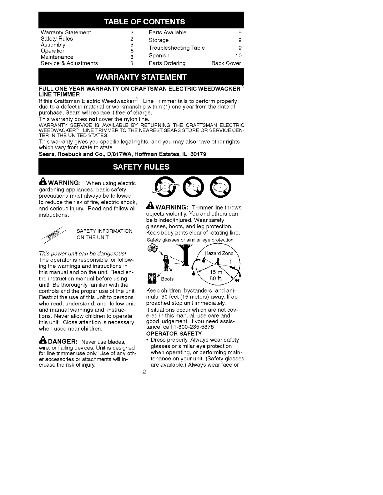
Warranty Statement 2 Parts Available 9
Safety Rules 2 Storage 9
Assembly 5 Troubleshooting Table 9
Operation 6
Maintenance 8 Spanish 10
Service & Adjustments 8 Parts Ordering Back Cover
FULL ONE YEAR WARRANTY ON CRAFTSMAN ELECTRIC WEEDWACKER ®
LINE TRIMMER
If this Craftsman Electric Weedwacker c_ Line Trimmer fails to perform properly
due to a defect in material or workmanship within (1) one year from the date of
purchase, Sears will replace it free of charge.
This warranty does not cover the nylon line.
WARRANTY SERVICE IS AVAILABLE BY RETURNING THE CRAFTSMAN ELECTRIC
WEEDWACKER _: LINE TRIMMER TO THE NEAREST SEARS STORE OR SERVICE CEN-
TER IN THE UNITED STATES.
This warranty gives you specific legal rights, and you may also have other rights
which vary from state to state.
Sears, Roebuck and Co., D/817WA, Hoffman Estates, IL 60179
_WARNIN_I: When using electric
gardening appliances, basic safety
precautions must always be followed
to reduce the risk of fire, electric shock,
and serious injury. Read and follow all
instructions.
_" SAFETY INFORMATION
ON THE UNIT
This power unit can be dangerous!
The operator is responsible for follow-
ing the warnings and instructions in
this manual and on the unit. Read en-
tire instruction manual before using
unit! Be thoroughly familiar with the
controls and the proper use of the unit.
Restrict the use of this unit to persons
who read, understand, and follow unit
and manual warnings and instruc-
tions. Never allow children to operate
this unit. Close attention is necessary
when used near children.
A
_1_ DANGER: Never use blades,
wire, or flailing devices. Unit is designed
for line trimmer use only. Use of any oth-
er accessories or attachments will in-
crease the risk of injury.
Q@©
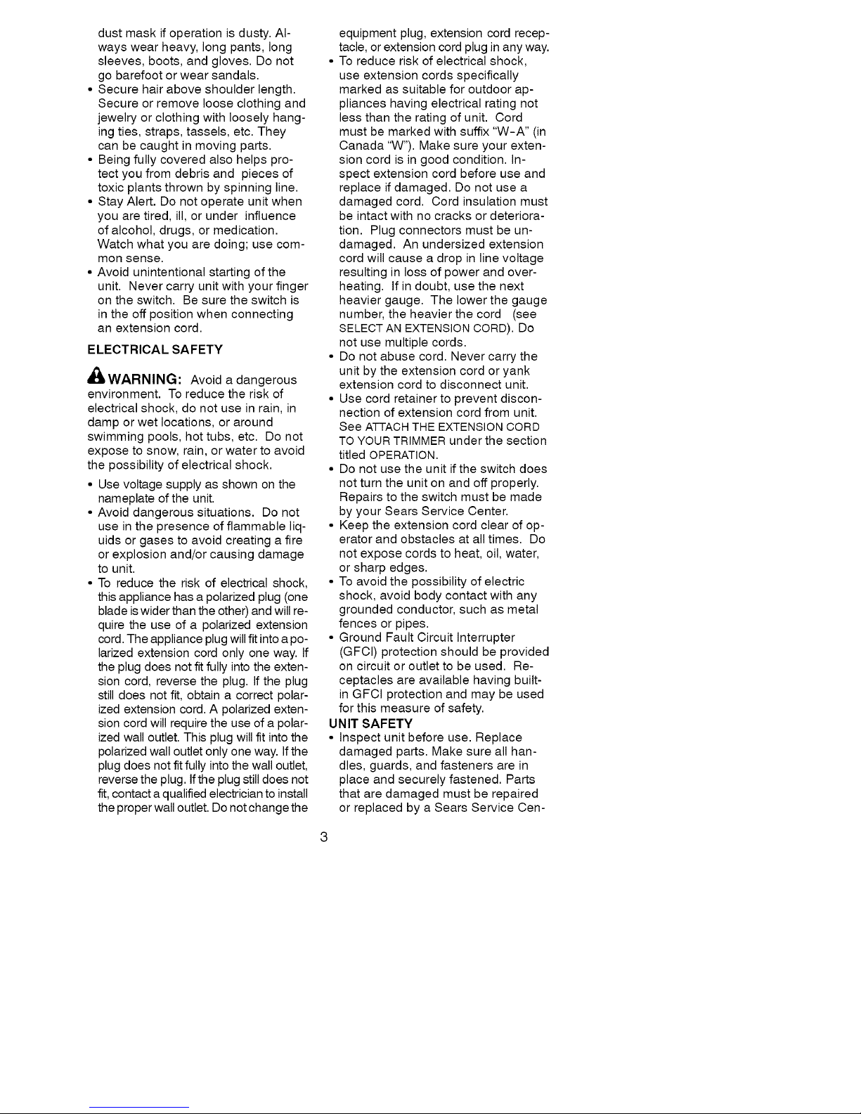
_WARNIN_I: Trimmer line throws
objects violently. You and others can
be blinded/injured. Wear safety
glasses, boots, and leg protection.
Keep body parts clear of rotating line.
Safety glasses or similar eye protection
Keep children, bystanders, and ani-
mals 50 feet (15 meters) away. If ap-
proached stop unit immediately.
If situations occur which are not cov-
ered in this manual, use care and
good judgement. If you need assis-
tance, call 1-800-235-5878
OPERATOR SAFETY
• Dress properly. Always wear safety
glasses or similar eye protection
when operating, or performing main-
tenance on your unit. (Safety glasses
are available.) Always wear face or
2
Page 3
dustmaskifoperationisdusty.Al-
wayswearheavy,longpants,long
sleeves,boots,andgloves.Donot
gobarefootorwearsandals.
•Securehairaboveshoulderlength.
Secureorremovelooseclothingand
jewelryorclothingwithlooselyhang-
ingties,straps,tassels,etc.They
canbecaughtinmovingparts.
• Beingfullycoveredalsohelpspro-
tectyoufromdebrisandpiecesof
toxicplantsthrownbyspinningline.
•StayAlert.Donotoperateunitwhen
youaretired,ill,orunderinfluence
ofalcohol,drugs,ormedication.
Watchwhatyouaredoing;usecom-
monsense.
• Avoidunintentionalstartingofthe
unit.Nevercarryunitwithyourfinger
ontheswitch.Besuretheswitchis
intheoffpositionwhenconnecting
anextensioncord.
ELECTRICALSAFETY
_WARNING:Avoidadangerous
environment.Toreducetheriskof
electricalshock,donotuseinrain,in
damporwetlocations,oraround
swimmingpools,hottubs,etc.Donot
exposetosnow,rain,orwatertoavoid
thepossibilityofelectricalshock.
• Usevoltagesupplyasshownonthe
nameplateoftheunit.
•Avoiddangeroussituations.Donot
useinthepresenceofflammableliq-
uidsorgasestoavoidcreatingafire
orexplosionand/orcausingdamage
tounit.
•Toreducetheriskofelectricalshock,
thisappliancehasapolarizedplug(one
bladeiswiderthantheother)andwillre-
quiretheuseofapolarizedextension
cord.Theapplianceplugwillfitintoapo-
larizedextensioncordonlyoneway.If
theplugdoesnotfitfullyintotheexten-
sioncord,reversetheplug.Iftheplug
stilldoesnotfit,obtainacorrectpolar-
izedextensioncord.Apolarizedexten-
sioncordwillrequiretheuseofapolar-
izedwalloutlet.Thisplugwillfitintothe
polarizedwalloutletonlyoneway.Ifthe
plugdoesnotfitfullyintothewalloutlet,
reversetheplug.Iftheplugstilldoesnot
fit,contactaqualifiedelectriciantoinstall
theproperwalloutlet.Donotchangethe
equipmentplug,extensioncordrecep-
tacle,orextensioncordpluginanyway.
•Toreduceriskofelectricalshock,
useextensioncordsspecifically
markedassuitableforoutdoorap-
plianceshavingelectricalratingnot
lessthantheratingofunit.Cord
mustbemarkedwithsuffix"W-A"(in
Canada"W").Makesureyourexten-
sioncordisingoodcondition.In-
spectextensioncordbeforeuseand
replaceifdamaged.Donotusea
damagedcord.Cordinsulationmust
beintactwithnocracksordeteriora-
tion.Plugconnectorsmustbeun-
damaged.Anundersizedextension
cordwillcauseadropinlinevoltage
resultinginlossofpowerandover-
heating.Ifindoubt,usethenext
heaviergauge.Thelowerthegauge
number,theheavierthecord(see
SELECTANEXTENSIONCORD).Do
notusemultiplecords.
• Donotabusecord.Nevercarrythe
unitbytheextensioncordoryank
extensioncordtodisconnectunit.
• Usecordretainertopreventdiscon-
nectionofextensioncordfromunit.
SeeATTACHTHEEXTENSIONCORD
TOYOURTRIMMERunderthesection
titledOPERATION.
• Donotusetheunitiftheswitchdoes
notturntheunitonandoffproperly.
Repairstotheswitchmustbemade
byyourSearsServiceCenter.
• Keeptheextensioncordclearofop-
eratorandobstaclesatalltimes.Do
notexposecordstoheat,oil,water,
orsharpedges.
•Toavoidthepossibilityofelectric
shock,avoidbodycontactwithany
groundedconductor,suchasmetal
fencesorpipes.
• GroundFaultCircuitInterrupter
(GFCI)protectionshouldbeprovided
oncircuitoroutlettobeused.Re-
ceptaclesareavailablehavingbuilt-
inGFClprotectionandmaybeused
forthismeasureofsafety.
UNIT SAFETY
• Inspect unit before use. Replace
damaged parts. Make sure all han-
dles, guards, and fasteners are in
place and securely fastened. Parts
that are damaged must be repaired
or replaced by a Sears Service Cen-
Page 4

ter.Theseincludeheadpartsthat
arecrackedorchipped,guards,and
anyotherpartthatisdamaged.
• Donotrepairunityourself.
• Useonly.065"(1.65mm)diameter
recommendedtrimmerline(see
SERVICEANDADJUSTMENTS).Never
usewire,rope,stringetc.
• Usespecifiedtrimmerspool.Make
surespoolisproperlyinstalledand
allpartsaresecurelyfastened.
• UseonlyCraftsmanreplacement
partsandaccessoriesasrecom-
mended.
CUTTINGSAFETY
• Inspectareatobecut.Removeob-
jects(rocks,brokenglass,nails,
wire,string,etc.)whichcanbe
thrownorbecomeentangledincut-
tinghead.
• Donotoverreachorstandonunsta-
blesupport.Keepfirmfootingand
balance.
• Keepthecuttingheadbelowwaist
level.Donotraisehandlesabove
yourwaist.Cuttingheadcancome
dangerouslyclosetoyourbody.
• Keepawayfromcuttingheadand
spinningline.
• Useunitproperly.Useonlyfortrim-
ming,scalping,andmowing.Donot
forceunit.Itwilldothejobbetter
andwithlessriskofinjuryattherate
forwhichitwasdesigned.
• Useonlyindaylightoringoodartifi-
ciallight.
MAINTENANCESAFETY
_WARNIN_I:Disconnectunitfrom
thepowersupplybeforeperforming
maintenance,orwhenchangingtrim-
merline.
• Maintainunitaccordingtorecom-
mendedprocedures.Keepcutting
lineatproperlength.Followinstruc-
tionsforchangingtrimmerline.
• Haveallserviceandmaintenance
notexplainedinthismanualper-
formedbyaSearsServiceCenterto
avoidcreatingahazard.
• Neverdouseorsquirttheunitwith
wateroranyotherliquid.Cleanunit
andlabelswithadampsponge.
Keephandlesdry,clean,andfree
fromoilandgrease.
• Keeptheairventscleanandfreeof
debristoavoidoverheatingthemo-
tor.Cleanaftereachuse.
TRANSPORTINGAND STORAGE
• Stop the unit and disconnect the
power source when not in use.
• Carry the unit with motor stopped.
• Store the unit so the line limiter blade
(on underside of shield) cannot
cause injury.
• Store unit indoors in a high, dry place
out of the reach of children. Store
unit unplugged.
DOUBLE INSULATION
CONSTRUCTION
This unit is double insulated to help
protect against electric shock. Double
insulation construction consists of two
separate "layers" of electrical insula-
tion instead of grounding.
Tools built with this insulation system
are not intended to be grounded. No
grounding means is provided on this
unit, nor should a means of grounding
be added to this unit. As a result, the
extension cord used with your unit can
be plugged into any polarized 120 volt
electrical outlet.
Safety precautions must be observed
when operating any electrical tool.
The double insulation system only pro-
vides added protection against injury
resulting from an internal electrical in-
sulation failure.
,_WARNING: All electrical repairs
to this unit, including housing, switch,
motor, etc., must be diagnosed and re-
paired by qualified service personnel.
Replacement parts for a double insu-
lated appliance must be recommended
by the manufacturer and identical to
the parts they replace. A double insu-
lated appliance is marked with the
words "double insulation" or "double
insulated". The symbol (square within
a square) [] may also be marked on
the appliance. Failure to have the unit
repaired by Sears service personnel
can cause the double insulation
construction to become ineffective and
result in serious injury.
SAVE THESE INSTRUCTIONS
Page 5

CARTONCONTENTS
Checkcartoncontentsagainstthefol-
lowinglist.
Model 358,799201
• Trimmer
• Shield
Examine parts for damage. Do not use
damaged parts.
NOTE: If you need assistance or find
parts missing or damaged, call
1-800-235-5878.
ASSEMBLY
,_/LWARNING: If received as-
sembled, review all assembly steps to
ensure your unit is properly assembled
and all fasteners are secure.
• Extend the tube until it snaps into
place.
ADJUSTING THE HANDLE
1. Loosen wing nut or knob on han-
dle.
2. Rotate the handle on the tube to an
upright position; place in a comfort-
able position and retighten wing
nut.
ATTACHING THE SHIELD
,_WARNING: The shield must be
properly installed. The shield provides
partial protection from the risk of
thrown objects to the operator and oth-
ers. Your unit is equipped with a line
limiter blade, which cuts excess line to
the proper length while running. The
line limiter blade (on underside of
shield) is sharp and can cut you.
NOTE: If shield is not properly
installed, damage to unit (including
motor failure) will result.
1. Align the installation arrow on the
shield with the installation arrow on
the motor housing (see illustration
below).
2. Insert the shield onto the motor
housing. Ensure cutting line re-
mains free to rotate and is not
caught between the shield and the
motor housing.
3. Twist the shield as illustrated until it
snaps securely into place. Make
sure the shield is facing the back of
the unit as shown on the front cov-
er of this manual.
ALIGN INSTALLATION ARROWS
Twist shield in
direction of
arrow to assemble
CAUTION: Sharp line limiter blade
Page 6

KNOWYOURTRIMMER
READTHISINSTRUCTIONMANUALANDSAFETYRULESBEFOREOPERATINGYOUR
UNIT.Comparetheillustrationswithyourunittofamiliarizeyourselfwiththelocation of
the various controls and adjustments. Save this manual for future reference.
Trigger Handle
\
_,_ ........ Assist Handle
/
Recessed Trigger Switch
Plug i
Cord Retainer
Motor
Housing
Semi-automatic
Head with .065"
Trimmer Line
/-
Air Vents J
/-
Tap Button
Debris Shield ......-"-_"_ ...... Line Limiter
Blade
RECESSED PLUG
The RECESSED PLUG is where you at-
tach your extension cord to the unit.
TRIGGER SWITCH
The TRIGGER SWITCH is used to turn
on the unit. Squeeze the trigger switch
to operate the unit.
LINE LIMITER BLADE
The LINE LIMITER BLADE cuts the
cutting line to the proper cutting length.
ASSIST HANDLE
The ASSIST HANDLE is used to help
hold and guide the unit.
SEMI-AUTOMATIC HEAD
The SEMI-AUTOMATIC HEAD holds cut-
ting line and rotates during operation.
TAP BUTTON
The TAP BUTTON is used to advance
the cutting line during operation and to
remove the spool during line replace-
ment.
OPERATING INSTRUCTIONS
Use only a voltage supply as specified
on your unit.
SELECT AN EXTENSION CORD
Extension Cord Gauge Chart
Length of Cord Gauge
25 Ft. (7.5 m) 18 Gauge
50 Ft. (15 m) 16 Gauge
100 Ft. (30 m) 16 Gauge
Extension cords are available for this
unit at Sears.
ATTACH THE EXTENSION
CORD TO YOUR TRIMMER
Loop your extension cord through the
handle and around the hook as
shown. Ensure the plug and cord are
firmly and fully engaged.
CORRECT OPERATING POSITION
Trimming
Page 7

_WARNING: Always wear eye
protection. Never lean over the trimmer
head. Rocks or debris can ricochet or
be thrown into eyes and face and
cause blindness or other serious injury.
When operating unit, stand as shown
and check for the following:
• Wear eye protection and heavy
clothing.
• Hold trigger handle with right hand
and assist handle with left hand.
• Keep unit below waist level.
• Cut from your right to your left to en-
sure debris is thrown away from you.
Without bending over, keep line near
and parallel to the ground and not
crowded into material being cut.
ADVANCING THE CUTTING LINE
Advance line by tapping bottom of cut-
ting head lightly on the ground while
unit is running at full speed. A metal
blade attached to the shield will cut the
line to the proper length.
TRIMMING
Hold the bottom of the trimmer head
about 3 in. (8 cm) above the ground
and at an angle. Allow only the tip of
the line to make contact. Do not force
trimmer line into work area.
Trimming
/
around trees, posts, monuments, etc.
This technique increases line wear.
Scalping
MOWING
Your trimmer is ideal for mowing in
places conventional lawn mowers can-
not reach. In the mowing position,
keep the line parallel to the ground.
Avoid pressing the head into the
ground as this can scalp the ground
and damage the tool.
Mowing
/
/
SWEEPING
The fanning action of the rotating line
can be used for a quick and easy
clean up. Keep the line parallel to and
above the surfaces being swept and
move the tool from side to side.
3 in. (8 cm)
Above Ground
SCALPING
The scalping technique removes un-
wanted vegetation. Hold the bottom of
the trimmer head about 3 in. (8 cm)
above the ground and at an angle. Allow
the tip of the line to strike the ground
Sweeping
Page 8

CUSTOMER RESPONSIBILITIES
WARNING: Disconnect power source before performing maintenance.
CARE & MAINTENANCE TASK WHEN TO PERFORM
Check for loose fasteners and parts Before each use
Check for damaged or worn parts Before each use
Inspect and clean unit and labels After each use
GENERAL RECOMMENDATIONS
The warranty on this unit does not cov-
er items that have been subjected to
operator abuse or negligence. To re-
ceive full value from the warranty, the
operator must maintain unit as instruct-
ed in this manual. Various adjustments
will need to be made periodically to
properly maintain your unit.
BEFORE EACH USE
CHECK FOR LOOSE
FASTENERS AND PARTS
• Housing Screws
• Assist Handle Screws
• Debris Shield
CHECK FOR DAMAGED OR
WORN PARTS
Contact Sears Service Center for re-
placement of damaged or worn parts.
• Trigger Switch - Ensure switch func-
tions properly by pressing and re-
leasing the trigger switch. Make sure
motor stops.
• Debris Shield - Discontinue use of
unit if debris shield is damaged.
AFTER EACH USE
INSPECT AND CLEAN UNIT AND LA-
BELS
• After each use, inspect complete unit
for loose or damaged parts. Clean
the unit using a damp cloth with a
mild detergent.
• Wipe off unit with a clean dry cloth.
REPLACING THE LINE
1. Remove the spool by firmly pulling
on the tap button.
2. Clean entire surface of hub and
spool.
3. Replace with a pre-wound spool
(#71-85837), or cut a length of 30
feet of .065" (1.6 mm) diameter
Craftsman® Pro Trimmer line. Use
of heavier lines could overload and
damage unit. Never use wire, rope,
string, etc., which can break off and
become a dangerous missile.
4. Insert one end ofthe line about 1/2
inch (1 cm) into the small hole in-
side the spool.
5. Wind the line evenly and tightly
onto the spool. Wind in the direc-
tion of the arrow found on the
spool.
6. Push the line into the notch, leav-
ing 3 to 5 inches (7 - 12 cm) un-
wound.
7. Insert the line into the exit hole in
the hub as shown in the illustration.
8. Align the notch with the line exit
hole.
9. Push the spool into the hub until it
snaps into place.
10. Pull on the line extending outside
the hub to release it from the notch;
otherwise, the unit will not function
properly.
Small
Hole_ //7//_2*Z_'_/
-"_<i I/'ISA_,'\'I"_--
I ,Lt\tt 7{ spool
Button
Line in Notch
Hub
Line exit hole
Page 9

USERREPLACEABLESERVICEPARTS
REPLACEMENTPART
Spoolwith.065"ProTrimmerLine
AssistHandle
BoltCarriage,1/4-20
WingNut
ShieldAssembly
PART NUMBER
71-85837
530401991
530401989
530016152
530402673
_WARNIN_I: Perform the follow-
ing steps after each use:
• Stop the unit and disconnect the
power source when not in use.
• Carry the unit with motor stopped.
• Store the unit so the line limiter blade
cannot cause injury.
TROUBLESHOOTING TABLE
• Store unit and extension cord indoors
in a high, dry place out of reach of
children. Store unit unplugged.
• Store unit with all guards in place.
Position unit so that any sharp object
cannot accidentally cause injury.
,_/LWARNING: Always stop unit and disconnect from the power source before
performing all of the recommended remedies below except remedies that re-
quire unit to be operating.
TROUBLE
Semi-automatic
head stops
under a load or
does not turn
when switch is
pressed.
Line does not
advance or
breaks while
cutting.
CAUSE REMEDY
1. Crowding trimmer line 1. Allow tip of line to do the cutting.
against material being
cut.
2. Electrical failure. 2. Contact your Sears Service Center.
3. Thrown circuit breaker. 3. Check Breaker Box.
4. Debris stopping head. 4. Remove debris.
1. Check line routing.
2. Rewind line tightly and evenly.
1. Line improperly routed
in head.
2. Line improperly
wound onto spool.
3. Incorrect line size
4. Not enough line
outside of head.
5. Dirt buildup on unit.
1. Line size is incorrect.
2. Incorrect spool.
3. Line is being crowded
against material being
cut.
1. Line improperly
routed in head.
2. Spool damaged.
1. Line improperly routed
in head.
2. Line size is incorrect.
3. Crowding line against
material being cut.
4. Spool worn or damaged.
Use only .065 in. (1.65mm) dia. line.
Remove cover and pull 4 in.
(10 cm) of line out of head.
Clean unit.
Use only .065 in. (1.65mm) dia. line.
Replace with correct spool,
Cut with tip of line fully extended.
5.
Line welds onto 1.
spool. 2.
3.
Line releases 1. Check line routing.
continuously.
2. Replace spool.
Line usage is 1. Check line routing.
excessive.
2. Replace spool.
3. Cut with tip of line fully extended.
4. Replace spool.
Line pulls back 1. Too little line outside 1. Remove cover and pull 4 in.
into head. of head. (10 cm) of line outside of head.
2. Line size incorrect. 2. Use only .065 in. (1.65 mm) dia. line.
 Loading...