

Page 1
xiViPORTANT MANUAL
Operator’s
Manual
“Tftrow Away
MODEL NO.
3Sa798260-32cc
CUSTOMER
ASSISTANCE
'1-800-235-5878'
ADAmER:
Read the Operator's Mamuii
and Follow All Warnings
and Safety Instructions.
Failure To Do So CanResult
in Serious Ityury.
Always Wear Eye Protection
m/CRAFTSMflN
32ce GAS BRUSHWACKER
2 Cycle Engine
• Assembly
• Operation
Fuel Mix 40:1
• Maintenance
• Repair Parts
TM
Sean, Roebuck and Co., Hoffman Estates, IL 6017P U.S.A.
Page 2
!ONE YEAR LIMITED WASRAMY ON CRAFTSMAN GAS - POWERED BRUSHWACKER® BEADED TRIMMBRt:
For one year from the date ofpurchase, when this Craftsman Gas-Powered Brushwackeris maintained, lubricated, and tuned
up accordingto the operating and maintenance instructions in the operator’s manual, Sears will repair, free of charge, any defect
in materials or workmanship.
This warranty excludes the blade, nylon line, spark plug, and air filter, which are expendable parts and become worn during
normal use.
If this Brushwacker is used for commercial purposes, this warranty applies for only 90 days from the date ofpurchase. If this Bnishwacker
is used for rental purposes, this warranty applies for only 30 days from date of purchase. This warranty applies only while this product is in
use in the United States. ,
WARRANTY SERVICE IS AVAILABLE BY RETURNING THE BRUSHWACKER TO THE NEAREST SEARS SERVICE CENTER IN THE
UNITED STATES. .
Thiswarrantygivesyouspecificlegalrights, and you may also have other rights which vary from state to state,
SEARS, ROEBUCK AND CO. DEPT.817WA HOFFMAN ESTATES, IL 60179
lABLE OF CONTENTS
WARNINGS iVND SAFETY INSTRUCTIONS
KNOW YOUR TOOL................................................................ 5
ASSEMBLY................................................................................. 6
FUELING YOUR ENGINE
STARTING YOUR ENGINE....................................................12
USING YOUR TOOL AS A BRUSIICUTTER
......................................................
......................
......................
11
14
USING YOUR TOOL AS A LINE TRIMMER
3
ACCESSORIES..............................;...................................................20
CUSTOMER RESPONSIBILITIES.....................................................21
REPiVIR PARTS LIST
INDEX
......................................................................................................31
...........................................................................
..............................
...16
2^
SPECIFICATIONS
ENGINE TYPE:
DISPLACEMENT:
ENGINE RPM:
IGNITION:
IGNITION TIMING:
CARBURETOR:
ENGINE ■OFF":
STARTER:
MUFFLER:
CLUTCH:
FUEL TANK: 17 fl, oz.
SHAFT LENGTH ; 31"
SPARK PLUG
SPARK PLUG GAP:
MODULE AIR GAP:
LUBRICATION:
CUTTING LINE:
BLADE
WHITE CONSOUDATED INDUSTRIES. INC.
MANUFACTURED UNDER ONE OR MORE OF THE FOLLOWING U,8. PATENTS;
4 D3S.813! 4,0S2,1g9i 4,112,«53; 4.181,820; 4,1«2,812: 4, 183,138; 4,188,833; 44ll.p®^
4!28S,«?fit 4.382,0«; 4,451,883; 4,788,185; 4,833,465; 4,841,928; 4,840,028) 5,020.225; A
D324,051. OTHER US. AND FOREIGN PATENTS PENDING.
2-Cyde, Air-C<xiled
32cc -
Operating — 7500
Idle -2800 -3200
Solid State
Spark Advance —
Non-adjustabtc
Diaphragm All Pasitions with
adjustable fuel mixture jets .
Push Button
Auto Rewind
Temperature Limiting (not spark
arresting; see Notice, p.6)
Centrifugal
71-83854 (CJ-14)
.025"
.010'7.014"
Gasotine/Oi! Mixture-40:1
,080" Diameter Sears Laser
Line*
4 point 8" Blade
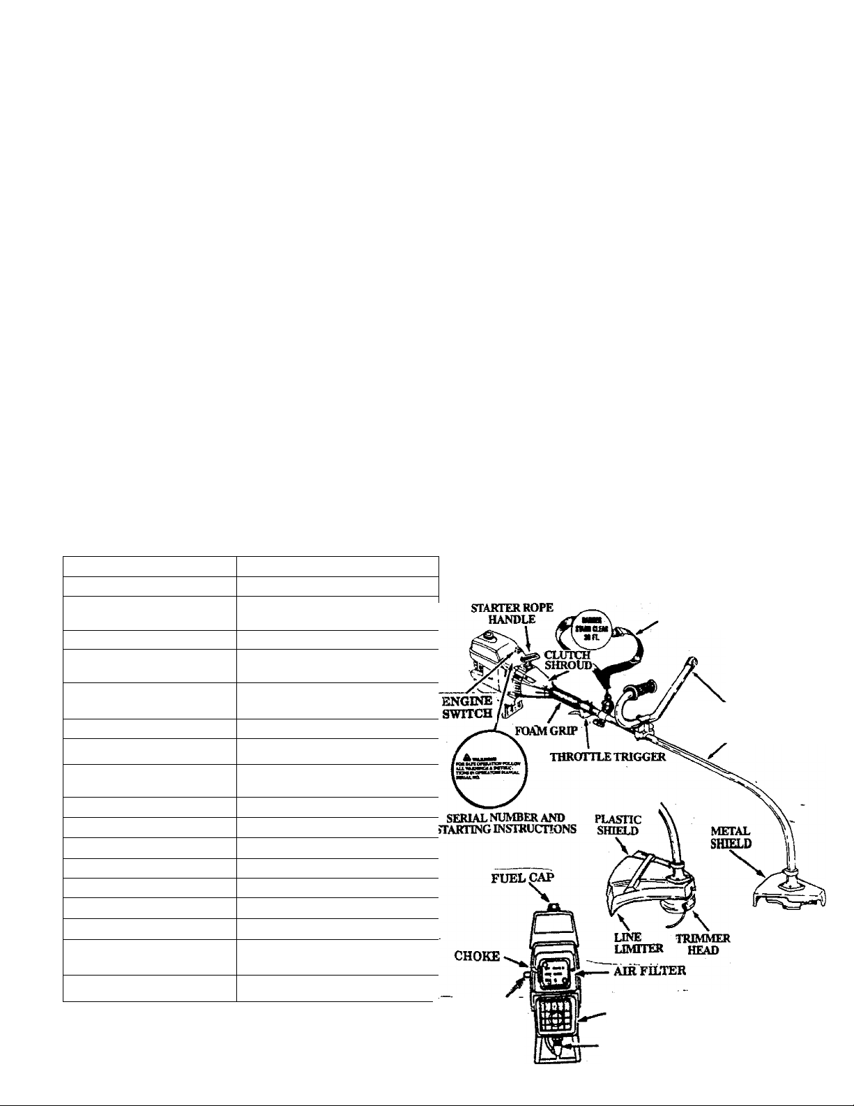
PRIMER BULB
SHOULDER STRAP.
HANDLEBAR
SAFETY LABELS
4TtKrrH
WEKDBLADK
MUFFLEB&
•MUFFLER
GUARD
SPARKPLUG
Page 3

A WARNINGS AND SAFETY INSTRUCTIONS
(See Additional Safety Instructions throughout this Manual) .
A DANGER - THIS POWER TOOL CAN BE DANGEROUS! Thlaimit cancauseserioua
ii^ury including amputation or blindnesa to the operator and others. The warnings and safety instruc
tions in this manual must be followed to provide reasonable safety and efficiency in iising the unit. The
operator is responsible for following the warnings and instructions in this manual and on the unit. Read
the entire Operator’s Manual before assembling and using the uniti Restrict the use of this unit to persons who read,
understand, and foÜow the warnings and instructions in this manual and on the unit.
Adanger
BLADE CAN THRUST VIOLENTLY
AWAY FROM MATERIAL IT DOES
■ NOT CUT.
- BLADE THRUST CAN CAUSE
AMPUTATION OF ARMS OR LEGS.
~ KEEP PEOPLE AND ANIMALS
30 FEET (10 METERS) AWAY.
TRIMMER LINE CAN THROW
OBJECTS VIOLENTLY.
- YOU CAN BE BLINDED
OR INJURED.
- WEAREYEANDLEG
PROTECTION.
Protection
BLADE'T^'^^
A WARNING
Leg Guards
Boots
Blade
Coasts
60 Foot (20 meter)
Hazard Zone
Stop Coasting
Blade by Contact
I with Cut
Material.
AWARNING
HAZARD ZONE FOR THROWN
OBJECTS.
- BLADE/TRIMMER LINE CAN
THROW OBJECTS VIOLENTIY.
- OTHERS CAN BE BLINDED
OR INJURED.
- KEEP PEOPLE AND ANIMALS
30 FEET (10 METERS) AWAY.
--------------------------------------------------------------
AWARNING
BLADE COASTS AFTER THE
THROTTLE IS RELEASED.
- THE BLADE CAN SERIOUSLY
CUT YOU OR OTHERS.
STOP THE BLADE WITH CUT
MATERIAL.
AWARNING
READ OPERATOR'S MANUAL
- FOLLOW ALL WARNINGS
AND INSTRUCTIONS.
Optfitof'i
Manual
sis
« FAILURUTODOeOCAN
RESULT IN SERIOUS INJURY.
Page 4

WARNINGS AND SAFETY INSTRUCTIONS... .(Continued)
> mi/J,9LnikJL JEli* Mi/ JL Je
Always wear safely eye protection.
Always wear heavy, long pants, long sleeves,
boots, and gloves, waring safety leg guards is rec
ommended. Do not go barefoot or wear sandals,
jewelry, short pants, short sleeves, loose clothing,
or clothing with loosely han^g ties, straps, tas
sels, etc.; they can be caught in moving parts. Be
ing fully covered will help protect you from pieces
of toxk plants such as poison ivy thrown by blade
or trimmer head which could be more of a hazard
than touching the plant itseE
Secure hair so it is above shoulder length.
Do not operate unit when you are tired, ill, or un
der the influence of alcohol, drop, or medication.
Wear hearing protection if you use the unit for
more than I-1/2 hours per day. .
Never start or run the engine inside a closed room
or building. Breathing eadiauat fumes can loll.
Keep handles free of oil and fuel.
Always use the handlebar and a properly adjusted
shoulder strap with a blade. See “Assembly.”
. UNITIMAINTENANCE SAFETY
Look for and replace damaged or loose parts be
fore each use. Look for and repair fuel leaks before
use. Keep the unit in good working condition.
Throw away blades that are bent, warped,
cracked, broken, or damaged in any other way.
Beplace trimmer head parts that are cracked,
chipped, broken, or damaged in any other way be
fore using the unit.
Maintain the unit according to recommended pro
cedures. Keep the blade sharp. Keep the cutting
line at the proper length.__________________
Use only .080” diameter SEARS Laser Line®.
Never use wire, rope, string, etc.
Install the reqxured shield properly before using
the unit. Use the metal shield for all weed blade
use. Use the plastic shield for all line trimmer use.
Use only specified blade or trimmer head; make
sure it is properly installed and securely fastened.
Never start engine with clutch shroud removed.
The clutch can fly off and cause serious ^ury
Be sure blade or trimmer head stops turning when
engine idles.
Disconnect the spark plug before performing
maintenance (except carburetor adjustments).
Make carburetor a^ustmenta with the lower end
supported to pre^nt the blade or trimmer line
from contacting any object. Hold the unit by hand;
do not use the shoulder stnqp for support.
‘ Keep others away when malting carburetor ad
justments.
Use only genuine SEARS accessories as rerom
mended for this unit.
.................................
Ifaituationê occur which are not covered in thie manual u*e care and good judgment.
CUSTOMER ASSISTANCE HOTUNE» 1 -800-23^878j,
---------------------------------
If you need euaistanee, contact your Autiuoriz&i Service Dealer or the
_ _
_________
• Have all maintenance and service not explained
in this manual performed by aij Authorized Ser
vice Dealer.
A FUEL SAFETY
• Mix and pour fuel outdoors.
• Keep away from sparks or flames.
• Use a container approved for fuel.
• Do not smoke or allow smoking near fuel or the
unit or while using the unit.
• Wipe up aU fuel mills before starting engine.
• Move at least 10 feet (3 meters) away from fueling
site before starting engine.
• Stop engine and allow unit to cool before remov
ing fuel cap.
• Empty the fuel tank before storing the unit. Use
up fuel left in the carburetor by starting the en
gine and letting it run until it stops.
• Store unit and fuel in an area where fuel vapors
cannot reach sparks or open flames from water
heaters, electric motors or switches, furnaces, etc.
A rtTfrriirTKri^ QA VV'TfV
• Inspect the area to be cut before each use. Remove
objects (rocks, broken glass, nails, wire, string,
etc.) which can be thrown or become entangled in
the blade or trimmer head.
• Keep others including duldren, animals, bystand
ers, and helpers outside the 60 foot (20 meter)
Haz^ Zone. Stop the engine immediately E you
are approached.
• Always keep engine" on the right-hand side of
our body
fold the unit firmly with both hands.
?
• Keep firm footing and balance. Do not over-
reacm.
• Keep blade or trimmer head below waist level.
• Do not raise the engine above your waist.
• Keep all parts of your bodv away from blade, trim
mer head, and mtifiler when engine is runnning.
• Cut from your right to your left.
• Use only for jobs explamed in this mamlal.
A TRANSPORTING AND STORAGE
• Stop the unit before carrying.
• Keep the muffler away from your body.
• Allow en^e to cool and secure unit before i
ing or trmisltirting it in a vehicle.
• Emply the rael tank before storing or transportingthe unit. Use up fuel left in the carburetor by
staitmg^eengineandlettingitrununtiHtstops.
• Store unit and fuel in an area where fUel vapors
cannot reach ^arks or open flames from water
heaters, electric motors or switches, furnaces, etc.
• Store unit so the blade or line limiter cannot acci
dentally cause injury The unit can be hung by the
bracket below engine or by tube.
• Store the tmit out of reach of children.
............................................
.................
I stor-
Exposure to vibratioiia throng prolonged use of gasoline powered hand tools could canae blood vessel or n^e
SAFETYNOnCB
damage in the fingers, hands, and wrists of people prone to circulation disorders or abnormal sweUings. Pro-
occur such as numbness, pain, loss of strength, change in sldn color or texture, or loss of feeling in the fingers,
hands orwrists, disconthiue theuse of this tool andsoekmediealattentten. An anti-vibration »lem does not
goarastM the ayoldaBoo of these probleiaa. Uiere who opcmte tools on « oonthtoal aBd regular basis
must memiter closely their physical condition and the condition of this tooL
Page 5
KMOW YOUR TOOL
A. IMTROmiCTlON
____________________
Your Weedwacker” is a high quality product designed for
tough jobs. Its versatility will help you make short work
of a variety of jobs.
Special Features Include:
. • Reversible4>point\¥eedBladeforgras$, weeds and
brush up to'/4 inch in diameter. -
• Semi—automatic line feed trimmer head for trim
ming, mowing, sweeping, and scalping.
UNPAGICING INSTRUCTIONS
1. Remove contents from the carton if you have not
done so.
2. Check parts against the list below.
3. Examine parts for damage. Do not use damaged parts.
4. Notify your Sears Store immediately if a part is miss
ing or damaged.
NOTE; Your unit has been shipped with a plastic
shipping guard over the primer bulb (see
“Specifications” for location). Remove and
discard the plastic shipping guard.
NOTE: It is normal to hear the fuel filter rattle in an empty
fuel tank.
___________
<
,
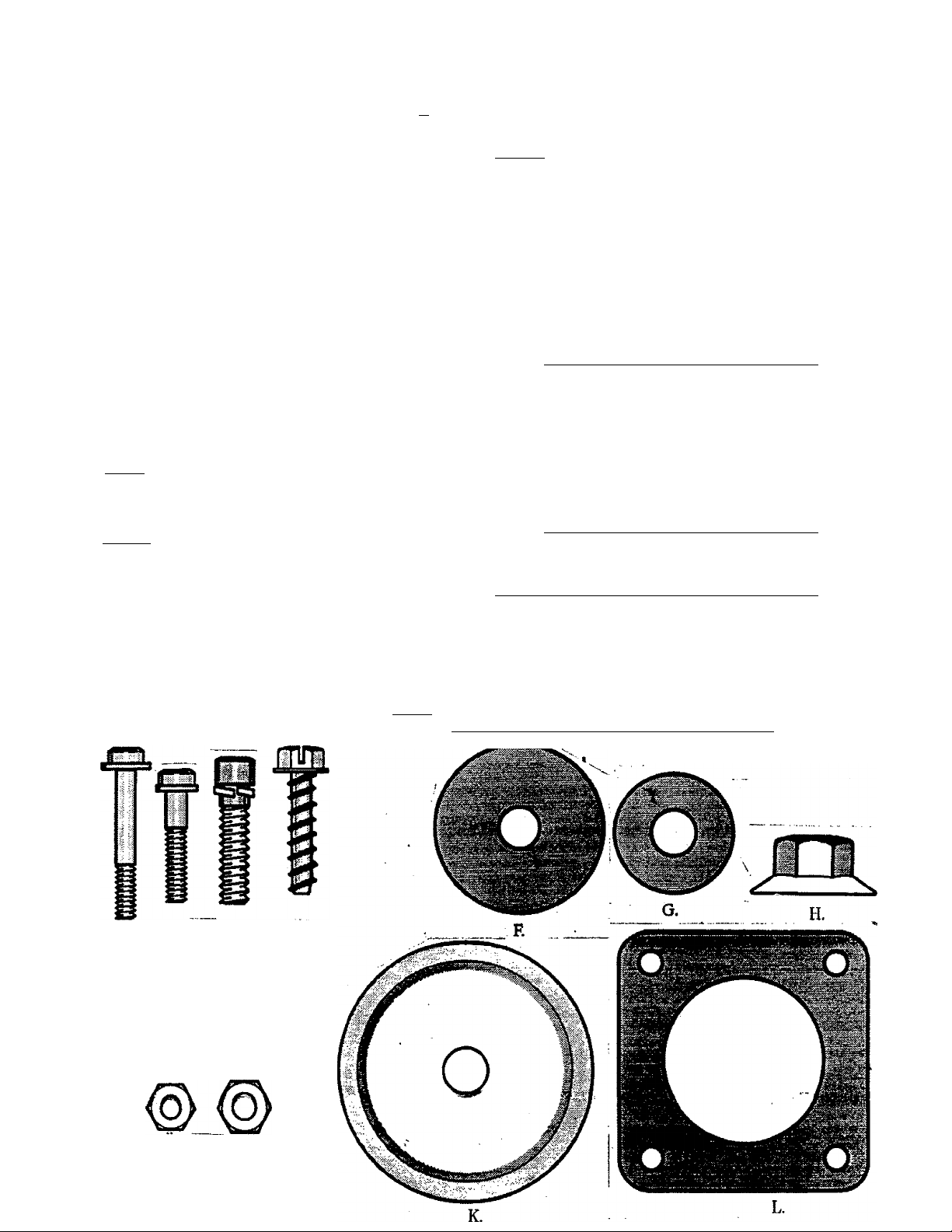
CARTON CONTENTS
KEY
Na
• '
•
■ :
-•-“1
"*• i
«,
* • j
■ •
•
•
^ •
'"V "'
■ A. B.
D.
E.
• ■■E .
*
1.
■J. , Hex Nut 1
K.
* L
Engine .
Drive Shaft/Bearing Housing Assembly
w/Safcty Labels
Handlebar
Plastic Shield - Trimmer Head
Trimmer Head
Metal Shield * Blade
Weed Blade - 8 inch, 4-point
Shoulder Strap w/Waming '
• 1
2-cycle Engine Oil
Operator’s Manual (not shown)
■ Lwse Parts Bag {not shown)
. (
LOOSE PARTS BAG CONTENTS:
Mounting Block • Handlebar 1
Cover-Handlebar 2
Shoulder Strap Clamp
T-Handle
Hex Wrench - Small I
Hex Wrench - Large 1
Flex Shaft Lube
Hex Screw - Engine
Screw-Handlebar
"Hex ScrcwT- Throttle Trigger Housing "
Screw - Plastic Shield
Square-Head Screw
Fiat Washer - Blade
Beveled Washer - Blade
Flange Hex Nut - Blade
Hex Nut - Engine 2
Large Cup Washer - Trimmer Head
Retention Plate - Metal Shield
QTY.
1
1
I
1
1
1
I
1
i
1
1
1
1
1
^ 2
8
1
4
1
1
1
1
1
1
D. HARDWARE USAGE
A. B. "C :D.
E.
NOTE; This Hardware is packaged in the Plastic Bag. Refer to
the Hardware reference letters below during assembly.
HARDWARE SHOWN ACTUAL SIZE
nMn
J.
Page 6
ASSEMBIiY
(If tool is received assembled, repeat all steps in this section to be sure assembly is correct pnd is ad
justed for the operator.)
PREPARATION
This Manual is designed to help you assemble the tool
and to provide its safe operation. It is important that
you read the entire manual to become familiar with
the tool before you begin assembly. If you have any
questions or need further assistance, call our
CUSTOMER ASSISTANCE HOTLINE at
1-800-235-5878.
1. Read your Operator’s Manual
2. Tools you will need;
— Hex Wrench provided with the tool.
— Adjustable Wrench
— Standard Screwdriver
ASSEMBLY STEPS (Refer to illustrations)
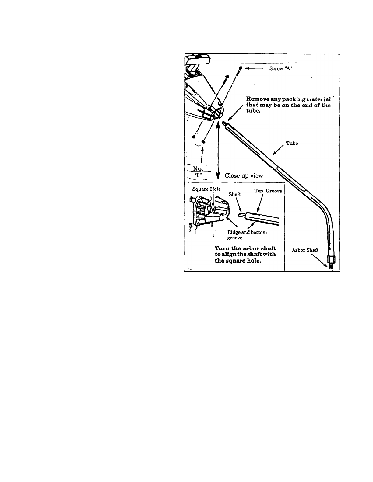
TUBE
• Place the two screws “A.” into the holes on the
engine as shown in the illustration. Make sure
screws are fully seated in the holes.
• Position the. nuts . “ I. ” in the lower holes.
• Tighten the screws with the hex wrench (pro
vided) just enough to hold the hardware to
gether while holding the locknuts with your
other hand.
• Remove the packing cover from the straight
end of the shaft housing if so equipped. Your
unit may not have a packing cover.
NOTE; Make sure the shaft inside the tube does
not fall out of the tube. Dirt on the shaft will sig
nificantly reduce the life of the unit. If the drive
shaft falls out of the housing, clean, re-lubricate,
and re-install. See “Drive Shaft Lubrication” in
the Customer Responsibilities section.
• Align the bottom groove on the tube with the
ridge on the lower wall of the engine opening.
• Turn the shaft to align the sguare end of the
shaft with the square hole inside the front
opening of the engine.
• Firmly push the tube into the en^ne opening
until the top groove is no longer visible.
• Tighten screws “A.” alternately with the hex .
wrench until secure.
__
-6
Page 7
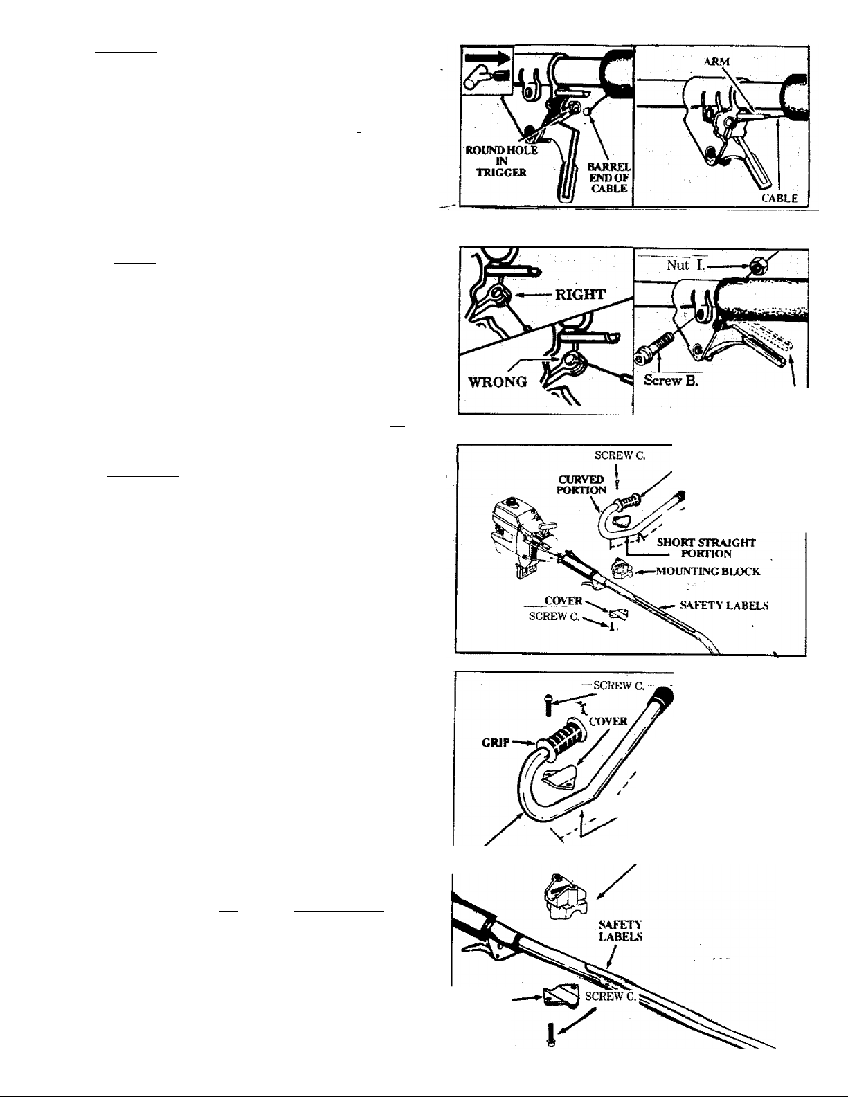
2.THmcrrrLE CABLE
fCAimowil Do not kink the throttle cable.
a. Slide the Throttle Trigger Housing away from the
Foam Grip.
NOTE: Before performing step “b”, push the barrel
end of thè throttle cable into the sheath until the
barrel contacts the sheath.____________ f
b. Insert the Throttle Cable through the tunnel in the
Foam Grip until the end of the Cable extends at
least 2 inches be^nd the Grip.
c. Hold the Trigger away from the Drive Shaft Hous
ing and insert the barrel end of the Throttle Cable
into the round opening in the Trigger. _________
NOTE: When inserting the barrel end of the
Throttle Cable into the round opening in the
Trigger, make sure that the barrel is completely
inserted and the Throttle Cable is located in the split
in the Arm. _______
, ’
d. Push the Trigger back into the Housing while guid
ing the Cable through the split in the aim. Guide^
the arm into the Foam Grip tunnel while replacing,
the Throttle Trigger Housing flush against the Grip?
e. Hold Trigger against the Foam Grip while insert- '
ing the screw “B.” and Nut “I.” See Caution below.
___________
_
_
1/8 "PLAY
ICAUTIOM; I Do not overtighten the screw. Make
sure the trigger will move freely. There must be at
least 1/8 "free play in the trigger. Make sure the
trigger will move freely so the engine can fully
return to idle when the trigger is released. The
trimmer head must not turn at Idle speed to avoid
serious injury to the operator and others.
__________
3.HANDLEBAR
i^WARNlNG
The handlebar mounting block must be placed above the
point of the arrow on the safety labels. The handlebar
is a barrier to keep the blade away from the operator’s
feet.
a. Position either side of the mounting block on the^
drive shaft Hou'sing above the arrow on the Safety
Labels.
b. Place one of the covers below the drive shaft Hous
ing and secure it to the mounting block with 2
screws finger^ti^ten only.
c.
Align the Handlebar with the straight barrier por
tion to the left and the curved portion to the right.
d. Position the Mounting Block between the arrows
on the short, straight section of the.Handlebar.
e. Place the remaining Cover over the Handlebar and
secure it with two screws “C.”; finger tighten onlyT
f. Be sure the Handlebar is installed correctly, then
- tighten each screw securely with a wrench.
________________
CURVED
PORTION
GRIP
\ BARRIER
PORTION
>
/ BARRIER
portion
Cs«' SHORT
X ^STRAIGHT
PORTION
MOUNTINt:
BLOCK
AW4RN1II0
The long, straight portion of the Handlebar must be
installed to provide a barrier between the operator
and the spinning blade.
COVER
Page 8
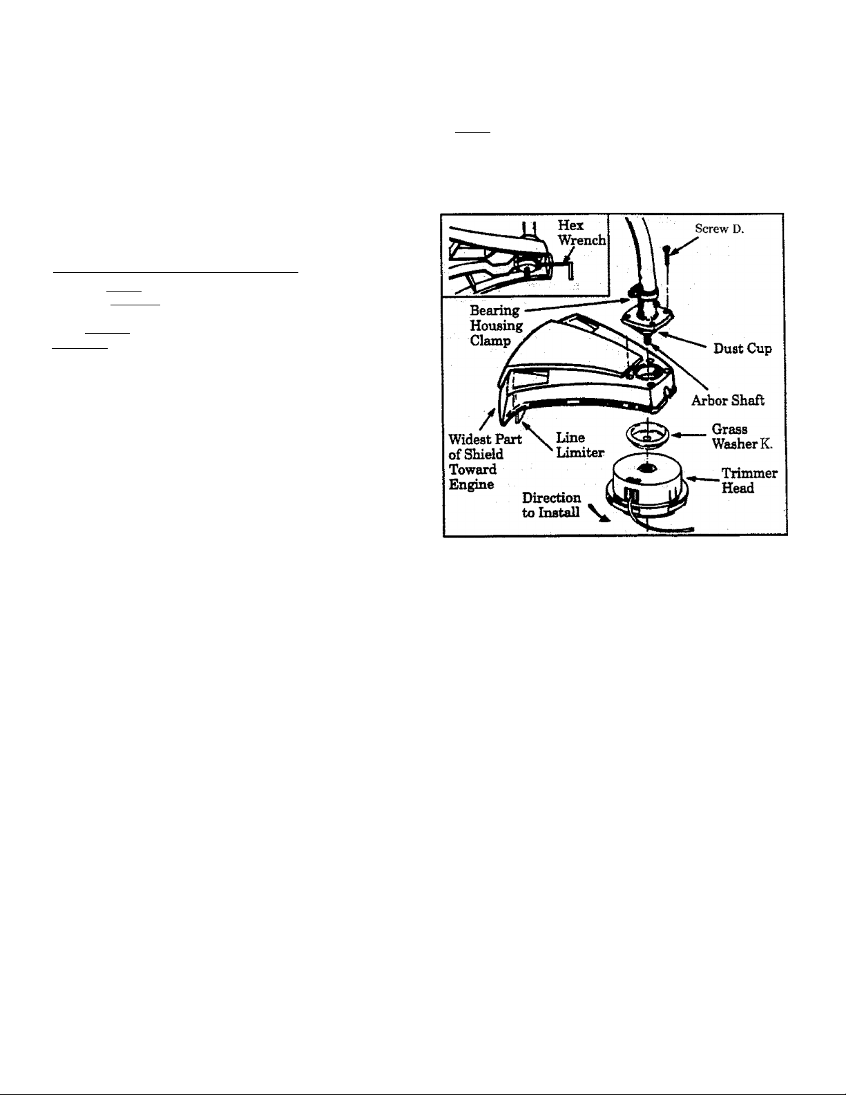
B.FOE LINE TMMMEB USE
A WARNING
The plastic shieM must be properly installed for
all Ime trimmer usage. The plastic shield pro
vides partial protection &om the risk of thrown
objects to the operator and others and is
equipped with a line limiter which cuts excess
line to the proper length. ____________________________
A WARNING
Failure to install shield in the position shown
can result in serious iipjury to the oper
ator. The length of the shield must be aligned
with the len^h of the drive shaft housing. Di
rect the widest part of shield toward the engine
NOTE; Remove the metal shield md blade before
inatAlling the plastic shield and tnmmer head.
1. Place the shield under the bearing housing and
align screw holes.
r.AtmONTl The line limiter (on the underside of
the shield) is sharp and can cut you. .
2. Insert screws “D.” through the bearing housing
into the shield. ^
Tighten the screws evenly and securely.
3.
Remove the packing cover from the arbor shaft if so
4.
equipped.
Install grass washer “K.” over the arbor shaft. Make
sure the grass washer is against and curved over the
dust cup. _ . ,
Start threading the trimmer head onto the arbor
6.
shaft. ^ . .
Align the hole in the dust cup with the hole in the
7,
center front of the bearing housing by turning the
dust cup. Then, insert the small hex wrench (pro
vided) into the migned holes to keep the arbor shaft
from turning. .
__________
'' ■
8. Tighten the trimmer head agEunst the washer and
dust cup while holding the hex wrench.
9. Remàve the Hex wrench.
NOTE; To remove the trimmer head, insert the
hex wrench into thè aligned holes in the dust cup
and hearing housing. Unthread the trimmer hean.
Be sure to store ^ass washer “K.”, plastic shield, 4
shield screws, and hardware with the trimmer head
for future use.
Page 9
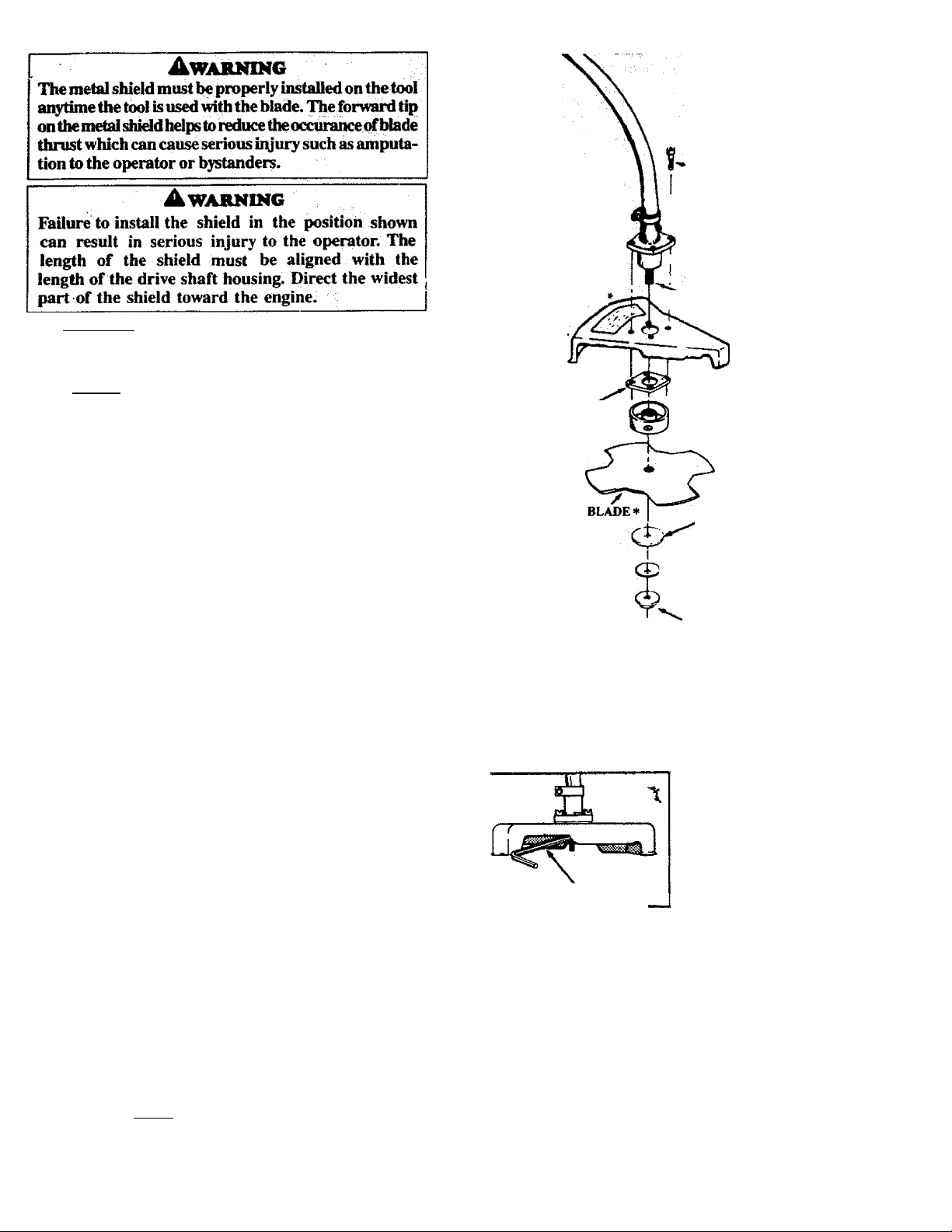
S. fUR WEED BLADE USE
■EAJUNti
HOUSINC^
CLAMf-^
•Screw“C.
CAUTION; I Wear protective gloves when
handling or perform ing maintenance on the blade to
help avoid injury.
NOTE; Remove the Plastic Shield, Trimmer Head,
and Grass Washer before installing the Metal Shield
and Blade.
a. Place the Metal Shield under the Bearing Housing,
aligning screw holes. Be sure wide end of metal shield
is toward the engine.
b. Position the retention plate “ L.” on the underside
of the Metal Shield and align screw holes. Make sure the
flat side of the Plate is against the Shield.
c. Insert screws “C.” (one at a time) through the Bearing
Housing, Shield, and Retention Plate.
d. Tighten the Screws evenly and securely with a hex
wrench.
e. Install the Dust Cup over the Arbor Shaft.
f. Install the Blade over Arbor Shaft, making sure the
hole in the center of the Blade is fitted around the raised
center .step on the Dust Cup.
g. Install flat washer “F.”, cupped washer “G.”, and
nut “H.”„ Be sure cupped washer “G.” is installed
as shown in (lower inset).
METAL
SHIELD
\
Retention
Plate“ L.”*'
1^ARBOR
SHAFT
DUST CUP
Washer “F.” •
Washer “G." •
(see inset)
Nut “H."*
V -
h. Line up the hole in the Dust Cup with the hole irt the
side of the Bearing Housing by turning the Dust Cup.
i. Insert the smal I hex wrench provided into the al igned
holestokeeptheArborShaftfromtuming.
j. Tighten nut *“II." firmly with a wrench while hold
ing hex wrench in position.
k. Remove the hex wrench.
l. Turn Blade by hand. If the Blade binds against the
Shield, the Blade is not centered. Reinstall the Blade.
m. Proceed to “Should Strap” instructions, this section.
NOTE; To remove the Blade, insert rod Into
aligned holes. Unthread the Hex Flange Nut and
• remove pans. Be sure to store the Retention Plate,
Hex Flange Nut, Beveled ’Vfeher, Flat ^^(hsher and
Metal StUeld with the Blade for safe keeping.
Cupped Side
Toward
Blade
HEX WRENCH
* Awarndig
Barts iMted with * are critical and must be
supplied by Sears. fUlure to use proper p<uts
can cause the blade to fly off and seriouBly hull
Washer “G.’
Page 10
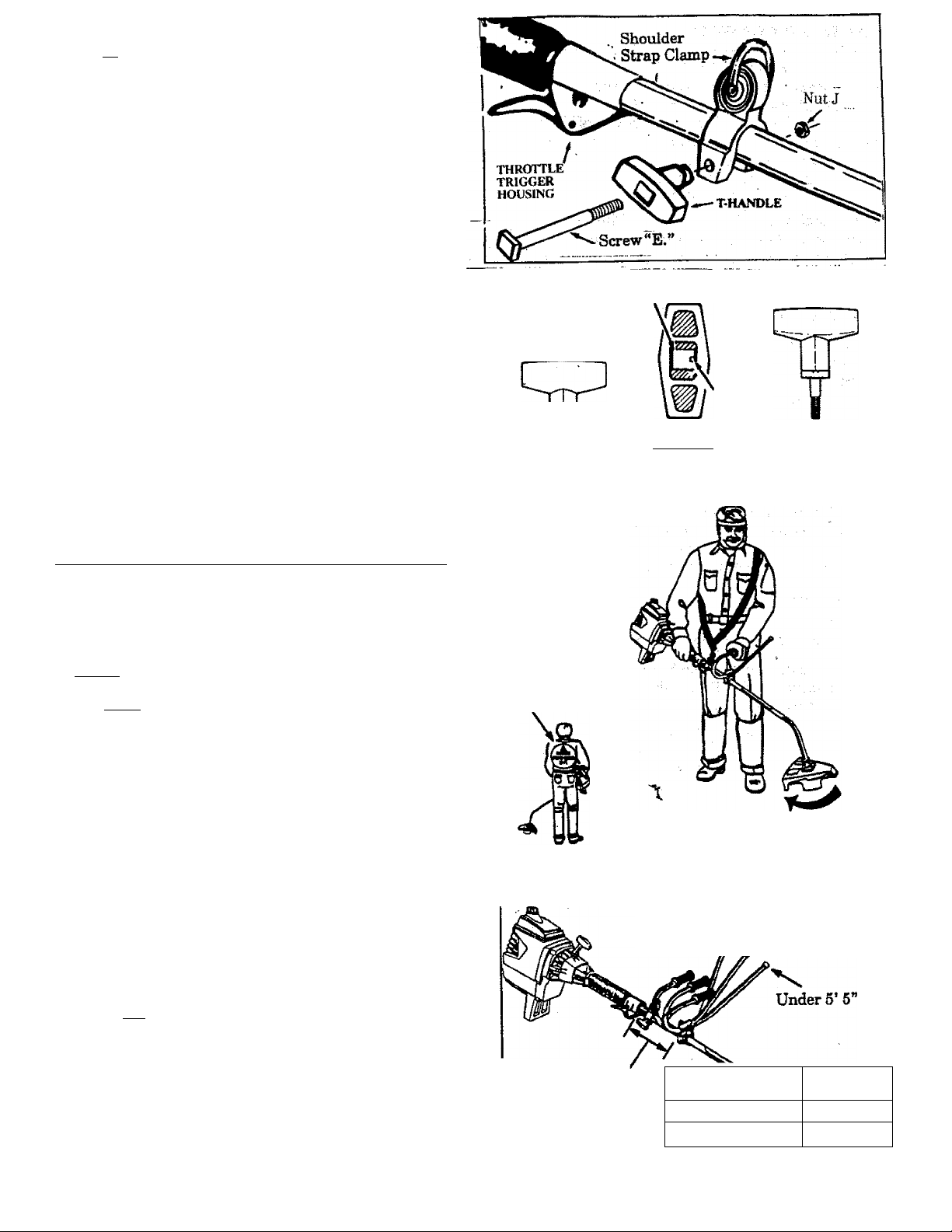
ft.SHOuuimsmAJ’CLAMi* „
a. Align the shoulder strap damp between the assist
hantUe and the throttle trigger housing.
b. Firmly push the shoulder strap damp onto the
drive shaft housing. Be sure that the shoulder
strap damp is installed with the „hex
shaped recession (on the damp) facing the same
side of the drive shaft housing as the barrier por
tion of the handlebar.
c. Drop the threaded end of screw “E.” through the
opening in the top of the T—handle.
d. Pull on the threaded end of the screw to bring the
square head of the screw past the pin inside the
T-handle.
e. Seat nut “ 1 in the hex-shaped recession on the
back side of the shoulder strap damp.
f. Insert the threaded end of screw “ E." through the
hole in the shoulder strap damp; thread the screw
into nut “ J. ” and tighten firmly by hand only.
...............................
_______________
__________ _____
Screw E.
SQUAREHEAD
SCREWSEATED
PIN
I. SHOULDER STRAP
A WARNING
Proper shoulder strap and handlebar adi«»**
ments before starting the engine are required for
safe and efficient use.
1. Try on shoulder strap and adjust for fit and balance
before starting the engine and beginning a cutting
operation. _
2. Place shoulder strap on vour left shoulder with the
Danger Bign on your back and hook to the ri|ht side
of your waist.
NOTE; A one-half twist is built in the shoulder strap
to allow the strap to rest flat on the shoulder.
To Tnake sure the strap rests flat on your body,
place the double portion across your front and the
single portion across your hack. .
3. Adjust the strap so that the hook will be about 10 in
ches below the waist when the hook is attached to
the shoulder strap.
4. Fasten the shoulder strap hook to the clamp and lift
the tool to the operating position.
5. Check for the following:
a. Left arm fuUy extended, hand holding handlebar
grip,
b. Right hand holding the top handle, fingers on
the throttie tri^r. .
c. Engine below waist level.
d. Shoulder strap pad centered on left shoulder.
e. Danger sign centered on your back.
f. Full weight of tool on left shoulder.
g. Without operator bending over, the blade or
trimmer head is near and parallel to the ground
and easily contacts material to be cut.
6. Modify these mitiai adjustments as necessary for
comfort and control but do not locate the handlebar
mounting block below the point of the arrow on the
safety labels. Do not locate the shoulder strap clamp
dlebar mounting Mock.
Position the handlebar for height. .
Be sure the handlebar is installed correctly, then
________________
tighten each screw secturefy with the larp hex
wrench.
10
.....
T-HANDLE
TOP VIEW OF
T-HANPLE
OPERATING POSITION
Danger Sign
Centered on
Your Back
POSITION HANDLEBAR FOR
Over 6’—*#
Distance A'
T-HANDLE AND
SCREW ASSEMBLED
Rotation
Direction
OPERATING HEIGHT
------
Operator’s Height
Less than 6 feet
6 feet & over
6’to 5’5"
Distance A
4 inches
2 inches
Page 11

FUELING YOUR ENGINE
BEFORE FUELING ENGINE:
AWARNESTG
Be sure to read the fuel safety information in the Warn
ings and Safety Instructions section on page 4 of this
manual before you begin.
If you do not understand the fuel safety section DO NOT
attempt to fuel your unit; seek help from someone that
does understand the fuel safety section or call the Cus
tomer Assistance Hotline at 1-800—235-5878,
GASOLINE
The two—Qfcle engine on this product requires a fuel mix
ture of regular unleaded gasoline and a high quality en
gine oil for lubrication of the bearings and other moving
parts. The correct fuel/oil mixture is 40:1 (see Fuel Mix
ture Chart). Too little oil or the incorrect oil type will
cause poor performance and may cause the engine to over
heat and seize.
Gasoline and oil must be premixed in a clean approved fuel
container. Always use fresh regular unleaded gasoline.
IMPORTANT! Experience indicates that alcohol
blended fuels called gasohol (or using ethanol or metha
nol) can attract moisture, which leads to oil/gas separa
tion and formation of acids during storage. Acidic gas
can damage the fuel system of an engine while in storage.
To avoid engine problems, the fuel system should be
emptied before storage, for 30 days or longer. Drain the
gas tank, then run the fuel out of the carburetor and fuel
Knes by starting the engine and letting it run until it
stops. Use fresh fuel next season. See STORAGE
instructions for additional information. Never use en
gine or carburetor cleaner products in the fuel tank or
permanent damage may occur.
2-CYCLE OIL:
CRAFTSMAN 40:1 2 cycle oil is strongly recommended.
This oil is specially blended with fuel stabilizers for
increased fuel stability (extends fuel life up to 5 times
longer) and reduced smoke. ■
If CRAFTSMAN 2 cycle oil is not available, use a good
quality 2 cycle AIR-COOLED engine oil that has a
recommended fuel mix 40:1.
IMPORTANT! Do not use:
• AUTOMOTIVE OIL
• BOAT OILS (NMMA, BIA. etc.)
These oils do not have proper additives for 2—cycle,
AIR-COOLED engines and can cause engine damage.
GASOLINE AND OIL MIXTURE
Mix gasoline and oil as follows:
• Consult chart for correct quantities.
• Do not mix gasoline and oil directly in the fuel tank.
FOR ONE GALLON:
• Pour 3.2 ounces of high quality, 2-qycle engine oil
into an empty, approved one gallon gasoline con
tainer.
• Add one gallon of regular unleaded gasoline to the
gallon container, then securely replace the cap.
Shake the container momentarily. ^
• The mixture is now ready for use. Fuel stabilizer
can be added at this time if desired; follow mixing
instructions orn^he label.
FUEL STABILIZER ,
Fuel stabilizer is an acceptable alternative in minimizing
the formation of fuel gum deposits during storage. Add
stabilizer to gasoline in fuel tank or storage container.
Always follow the fuel mix ratio found on the stabilizer
container. Run engine at least 10 minutes after adding
stabilizer to allow the stabilizer to reach the carburetor.
You do not have to drain the fuel tank for storage if you are
using fuel stabilizer.
CRAFTSMAN 40; 12 cycle engine oil ii specially Wended
with fUel stabilizers. If you do not use this Sears oil, you
can add a fuel stabilizer (such as Craftsman No. 33500) to
your fuel tank.
FUEL MIXTURE CHART
40:1 FuehOil Mix Ratio
Gasoline
1 gallon
1.25 gallons
2.5 gallons
Oil (fl. oz.)
3.2
4.0
8.0
-
Page 12
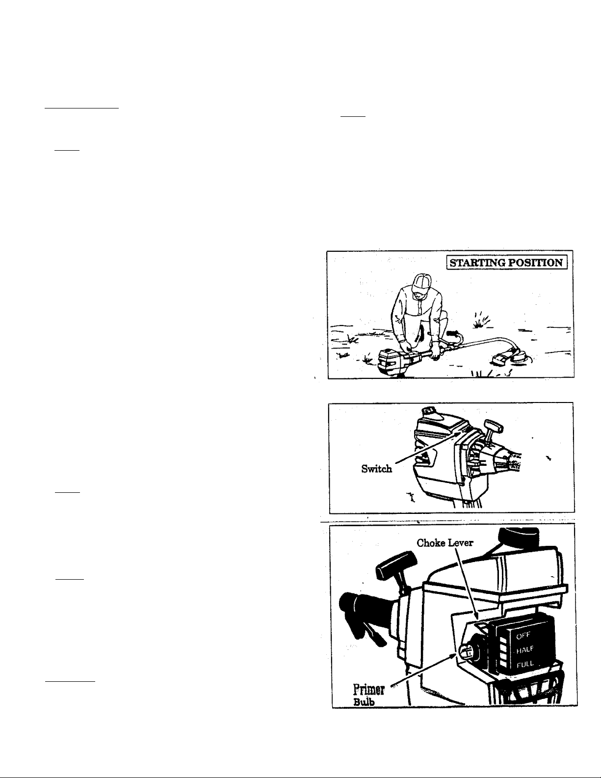
C. STARTING IMSmUCnONS (For location
BEFORE STARTING THE ENGINE:
• Fuel engine. Move 10 feet (3 meters) away from fuel
ing site.
A WARNING ^ ~
The trimmer head will turn when the engine
starts, ■
• Rest engine and shield on ground, supporting trim
. mer head off ground.
NOTE; Remove and discard the plastic shipping
guard on the primer bulb (if so eqtiipped).
STARTING A COLD ENGINE OR WARM ENGINE
AFTER RUNNING OUT OF FUEL:
• Make sure the switch is in the "On” position.
• Move the choke lever to the “Full Choke” position.
• Slowly press the primer bulb 6 times.
• Squeeze and hold the throttle trigger. Keep the
throttle trigger fully squeezed until tm engine runs
smoothly.
• PuU starter rope sharply 5 times.
Mom The en^
start before the 5
mediately.
________________________________
of controls, refer to “Specifications,”)
• Squeeze and hold the throttle trigger. iCeep iAe
throttle trigger fully squeezed until the engine runs
smoothly.
» Pull starter rope sharply until engine runs, but no
more than 5 pulls.
• Allow the engine to ran 15 seconds, then move the
choke lever to “Off Choke.”
NOTE; If engine has not started, pull starter rope 5
more pulls. If engine still does not ran, it is probably
flooded. Proceed to “Starting a Flooded Engine.”
• To stop the engine, move switch to the “Off” position.
STARTING A FLOODED ENGINE;
Flooded en^es can be started by placing the switch
in the “On” position and the choke lever in the “Off
Choke” position; then, puH the rope to clear the en
gine of excess fiiel. This could require pulling the
starter rope many times depending on how badly the
unit is flooded.
If the unit still doesn’t start, саП the Customer Assis
tance Hotline at 1—800—235—6878.
• Move the choke lever to the “Half Choke” position.
• PuR the starter rope sharply until the engine runs,
but no more than 6 pulls. .
ишт If the enmne has not started after 6 pulls (at
half choke), check to make зггге the switch and the
choke lever are in the proper positiona. Then, move
the choke lever to the ‘'Full Choke” position and
press the primer bulb 6 times; squeeze and hold the
throttle trigger and ргШ the starter rope 2 more
times. Move the choke lever to “HalfChoke” and pull
the starter rope until the engine runs, but no more
than 6 more pulls.
NOTE; If the engine still has not started, it is prob
ably flooded. Proceed to “Starting a Flooded En
gine”
• Allow the engine to run 15 seconds, then move the
choke lever to “Off Choke." Allow the unit to run for
30 more seconds at “Off Choke” before releasing the
throttle trigger.
NOTE: If engine dies with the choke lever at the “Off
Choke” position, move the choke lever to “Half
Choke” and pull the rope until the engine runs.
• To stop the engine, move the switch to “Off.”
_
____
A WARNING
Avoid any bodily contact with the muffler when
atarting a warm engine. A hot muffler can cauae
seriousbuma._________________
STAKTOIO A WASM ШОШЕ THAT ИА1 NOT
ЯШ OOT OF FUIX.|
a Make sure the switch is in the "On” position.
* Move the choke lever to the “Half Choke” position.
12
Page 13

D. OPERATING INSTRUCTIONS
• When using the blade, bring the engine to full
throttle before entering the material to be cut. The
blade has maximum cutting power at fuU throttle and
is less likely to bind, stall, or cause blade thrust,
which can result in serious iiyury to the operator or
others. Refer to “Guard Against Blade Thrust”.
> When using the trimmerhead, do not run the en
gine at a higher speed than necessary. The cutting
line will cut efficiently when the engine is run at less
than full throttle. At lower speeds, there is less engine
noise and vibration. The cutting line will last longer
and will be less Hkely to “weld” onto the spool.
^ If the blade or trinuner head does not turn
when the engine is accelerated, make sure the
tube is properly seated in the engine shroud.
► Always release throttle trigger and allow en
gine to return to idle speed when not cutting.
• The blade or trimmer head should not turn
when the engine runs at idle speed. If the blade
or trimmer head on your unit turns when the engine
is at idle speed, refer to “Trouble Shooting Chart.”
I To stop engines
• Release the throttle trigger.
• Move ignition switch to the “Off” position.
• Stop the blade by allowing the “9 o’clock” posi
tion to contact cut material. ^
_______________
A WARNING
The blade continues to spin after the engine is
turned off. The coastingblade can throw objects
or seriously cut you if accidentally touched.
Stop blade by contacting the left-hand side of
the coasting blade with material alreac^ cut.
Awarning
The operator or others must not try to clear
away cut material with the engine running or
the made tuimihg to avoid serious injury. Stop
engine and hlacfe before removing materials
wrapped around blade.
MOTES
13
Page 14
USING YOUR TOOL AS A WEEDCUTTER - w/BLADE
(The 4 point, 8 inch blade ie designed to cut grass, weeds and woody brush up to 1/2 inch diameter.)
A DANGER - THIS POWER TOOL CAN BE DANGEROUS!
This tool can came seriom injury including amputaUon or blindness to the operator and others. The warnings and safety
instructions in this manual must be followed to provide reasonable safety and efficiency in ming this tool. The operator is
responsible-for following the warnings and instructions in this manual and on the tool. Read the entire Operator’s
Manual before using this tool! Restrict the use of this power tool to persons who read, understand and
follow the warnings and instructions in this manual and on the tool.
A DANGER - BLADE THRUST When the spin
ning blade contacts anything it does not cut, a dan
gerous reaction can occur earning the entire tool and
operator to be thrust violently in any direction. This
reaction is called Blade Thrust. As a result, the op
BLADE THRUST
erator can lose control of the tool. Use handlebar,
shoulder strap.
Make sure others are at least 30 feet (lO me
ters) away. Keep blade sharp. Cut at full
throttle and from ^ur right to left. Keep
hands, feet and tool In proper position; refer to
“Guard Against Blade Thrust.”
and r .......................................
shield in place._. ke^ _
8 inch WEED BLADE #7l-8573S‘
Leg Guards
\ \
Place Shield Boots
l°n II
Thrown
Object
1” ARBOR
OPENING:
60 Foot
(20 meter)
Hazard
Zone
AdANGER - PROPER BLADE
Use only the 4 point, 8 inch blade and proper
' hardware. The me of any other parts can result in
seriom injury. Do not use any accessory or at
tachment other than those recommended by
the manufacturer for use with this tool. Blades
that are bent, warped, cracked, broken, or damaged
can fly apart and came seriom injury. Do not use.
Throw away.
A WARNING - THROWS OBJECTS
The rapidly moving blade causes objects to be
thrown violently. The shield will not provide com
plete protection to the operator or others. The op
erator must wear a safety face shield or gog-
[les. Alwa3?B wear safety leg guards and boots.'
eep others at least 30 feet away.
AwABNING - HAZARD ZONE
This tool will throw obj^s and cut. Keep others
including children, animals, bystanders, and
helpers at least SO feet (10 meters) away from
the operator and tool. Stop the engine and
blade immediately if you are approached.
NOTE: In areas where other people and animals are
present, such as near sidewall^, streets, houses, etc.,
It is strongly recommended that the operator use the
buddy system; that is, have another person serve as
a “look out,” keeping himself and others at least 30
feet (10 meters) away from the operotor,
%d
^WARNING - COASTING BLADE
The blade contmues to spin after the engine is
stopped or the throttle is released. The coasting
blade can thrust, throw objects, or seriously cut you
if accidentally touched. Stop blade by leaving it
in contact with material already cut. Use the
*'9 o’clook” poiition u the point of oontact.
Page 15
A. BLADE SAFETY
OPERATOR SAFETY
1.
a. Always wear a safely face sMeM or gog
gles, See “Accessories.
b. Always wear heavy, long pants, long
sleeves, boots, gloves and safety leg
guards. See “Accessories.” Do not wear loose
clothing, jewelxT, short pants, short sleeves,
sandals, or go barefoot. Secure hair so it is
above shoulder length.
Do not operate this tool when you are
c.
tired, ill or under the influence of alco
hol, drugs or medication-
1. Always use the handlebar and a properly
adjusted shoulder strap. See ‘Assemoly.”
e. Do not swing the tool with such force
that you are in danger of losing your bal
ance.
Never start or run the engine inside a
f.
closed room or building. Breathing exhaust
fumes can kiE.
Keep handles free of oil and fuel.
2. TOOL SAFETY
Inspect the entire tool before each use.
a.
Replace damaged parts. Check for fuel leaks
and make sure all fasteners are in place and se
curely fastened.
Be sure the metal shield is properly at
b.
tached. The metal shield must be installed for
all blade usage.
d. Be sure the blade stops turning when the
engine idles. See “Trouble Shooting Chart.”
e. Make carburetor adjustments with the
lower end supported to prevent the blade
from contacting any object. Hold tool by
hand; do not use shoulder strap for support.
f. Keep others away when making carbure
tor adjustments.
3. CUTTING SAFETY
a. Inspect the area to be cut before each
use. Remove objects (rocks, broken glass,
nails, wire, string, etc.) which can be thrown or
become entangled in the blade.
b. Always keep the engine on the right side
of your body. Hold the tool firmly with both
■ hands.
c. Keep firm footing and balance. Do not
over-reach.
d. Keep blade below waist level.
e. Do not raise the engine above your waist.
The blade can come dmgerously close to your
body.
f. Cut at full throttle .
g. Cut from your right to your left.
h. Use only for jobs explained in this man
ual. Do not use the blade as an edger. The
. shield does not provide adequate protection.
B. GUARD AGAINST BLADE THRUST
* Blade Thrust is a reaction that only occurs when
using a bladed tool. This reaction can cause seri
ous uyury such as amputation. Carefully study
this section. It is important that you understand
what causes blade thrust, how you can reduce the
chance of its occurring, and how you can remain
in control of the tool it blade thrust occurs.
• The forward tip on the shield helps to reduce the
occurrence of blade thrust but cannot prevent the
occurrence. The operator must follow the warn
ings and safety instructions in this section to
lessen the chance of blade thrust occui^g and to
maintain control of the tool if the reaction does oc
cur.
1. WHAT CAUSES BLADE THRUST. Blade
Thrust can occur when the spinning blade con
tacts an object that it does not cut. This contact
causes the blade to stop for an instant and then
suddenly move or “thrust” away from the object
that was hit. The “thrusting” reaction can be vio
lent enough to cause the operator to be propeUed
in any direction and lose control of the tool. The
uncontrolled tool can cause serious iiyury if the
blade contacts the operator or others.
2. WHEN BLADE THRUST OCCURS, Blade
thrust can occur without warning if the blade
Rfiftgs, stalls, or binds. This is more likely to occur
in «resi wher9 it is c^sult to see the material be
ing cut. By using the tool properly, the occurrence
of blodc thrust wUl be reduced and the operator
will be less likely to lose control.
3, REDUCE THE CHANCE OF BLADE THRUST
a. Cut only grass, weeds and woody brush up
to 1/2 incn diameter. Do not let the blade con
tact material it cannot cut such as stumps, rocks,
fences, metal, etc., or clusters of hard, woody
brush having a diameter greater than 1/2 inch.
b. Keep the blade sharp. A dull blade is more
likely to snag.
c. Cut only a fall throttle. The blade has maxi
mum cutting power at full throttle and is less
likely to bina or stall,
<L “Peed" the blade deliberately and not too
rapidly. The blade can thrust away if it is fed too
rapidly.
creases the cutting action.
15
Page 16
4. MAINTAIN CONTROL
a. Use tlie shoulder strap and keep a firm
grip on the tool with both hands. A prop
erly àcyuflted shoulder strap will support the
weight of the tool, freeing your anna and hands
to control and guidé the cutting motion.
Keep firm
footing and balance.
G. CUTTING METHODS
1. Establish a rhythmic cutting procedure.
a. Plantfeet firmly, comfortably apart.
b. Cut while swingingthe upper part of your body
from right to left.
c. Move forward to the next area to be cut after
the return swing and plant feet once more.
2. Use the 8 o’clock to 10 o’clock position for
cutting.
3. Stop the engine and blade, then uncUp the
shoulder strap from the tool before clearing
cut material.
4. To reduce the chance of material wrapping
around thé blade, follow these steps:
a. Cut at fuU throttle.
b. Swing the tool into material to be cut from
your right to left.
c. Avoid the material just cut as you make the re
turn swing.
Keep the blade below waist leTel. It will he
easier to maintain control of the tool. '
Do not raise the engine above your waist
as the blade can come dangerously close to
your body.
Do not swing the tool with such force
that you are in danger of losing your bal
ance. '' '
Direction to Cut
Cut Between
the 8 o’clock
and 10 o’cloc]
Position
Awarning
The operator or others must not try to clear
awav cut material with the engine runnJi^ or
the made turning to avoid serious Injury. Stoi
engine and Made before removing materii
wrapped around blade.
USING YOUR UNIT AS A LINE TRIMMER
The rapidly moving line causes objects to be
thrown violently. The shield will not provide
complete protection to the operator or others.
The operator must wear a safety f^e
shield or goggles. Always wear hea^,
longpants and boots. Keep others at least
30 feet (10 meters) away.
WARNING - HAZARD ZONE
This tool will throw objects and cut. Keep oth
ers including children, animals, bystand
ers and helpers at least 30 feet (10 meters)
away from the operator and tool. Stop
the engine if you are approached, ^ "
A WARNING - DAMAGED
Trimmer head parts that are chipped, cracked
or damaged in any other way can fly apart and
cause serious ityury. Do not use. Replace
damaged parts before using the tool. >
wahning-throws objects
1
TRIMMER HEAD
A. LINE TRIMMER SAFETY
1. OPERATOR SAFETY
a. Always wear eye protection when operating,
16
iervicing, or performing maintenance on your
b. Do not operate this tool when you are tired, ill
or under the influence of alcohol, drugs, or
medication,
Page 17
с.
Always wear heavy, long pants, boots, and
gloves. Do not go barefoot or wear sandals,
short pants, jewelry, loose clothing, or clothing
with loosely hanging straps, ties, tassels, etc.;
they can be caught in moving parts. Secure
hair so it is above shoulder length; Being fully
covered will help protect you from pieces of
toxic plants such as poison ivy thrown by the
blade, which could be more of a hazard than
touching the plant itself.
Do not swing the tool with such force that you
are in danger of losing your b^ance.
e.
Never start or run the engine inside a closed
room or building. Breathing exhaust fumes
can kill. •
Keep handles free of oil and fuel.
f.
TOOL SAFETY
a. Inspect the entire tool before each use. Re
place damaged parts. Check for fuel leaks and
make sure all fasteners are in place and se
curely fastened.
b. Use only .080” diameter SEARS Laser Line. Never
use wire, rope, string, etc. _
__ __
c. Be sure the shield is properly attached." “
d. Make sure trimmer head is properly installed
and securely fastened. Refer to “Assembly.”
e. Be sure trimmer head stops turning when en
gine idles. See “Carburetor Adjustments.”
f. Make carburetor adjustments with the drive
shaft housing supported to prevent the trim
mer line from contacting any object.
g. Keep others away when making carburetor ad
justments.
h. Use only acces^ries or attachments as recom
mended by Sears forthis tool.
CUTTING SAFETY
_______
. .
a. Inspect the area to be cut before each use. Re
move objects {rocks, broken glass, nails, wire,
string, etc.) which can be thrown or become en
tangled in the trimmer head.
b. Always keep the engine on the right side of
your body.
c. Hold the tool firmly with both hands.
d. Keep firm footing and balance. Do not over
reach.
e. Keep the trimmer head below waist level.
f. Do not raise the engine above your waist.
g. Keep all parts of your body away from the trim
mer line and muffler when engine is running.
h. Use only for jobs explained in this manual.
B. TRIMMER LINE ADVANCE
• The trimmer line will advance approxi
mately 2 inches each time the bottom of the
trimmer head is tapped on the ground with
the engine running at full throttle.
• The most efficient line length is the maxi
mum length allowed by the line limiter.
• Always keep the shield in place when the
tool is being operated. Figure 35 .
• To Advance Line:
1. Operate the engine at full throttle.
2. Hold the trimmer head parallel to and above
the grassy area.
3. Tap bottom of trimmer head lightly on ground
onetime. Approximately' 2 inches of line
will be advanced with each tap. , ___ _
NOTE; Always tap trimmer head on a grassy
area. Tapping on surfaces such as concrete or
asphalt can cause excessive wear to the trim
mer head.
NOTE; If the line is worn down to two
inches or less, more than one tap will be re
quired to obtain the most efficient line length.
Use only .080” diameter Scars leaser Line. Other
A WARNING
sizes, of ^line^will not advance properly. Do.
not use_ other 'materials .such..as wirè;._
string, rope, etòrWiré can break off during cut
ting and become a dangerous missile that can
possibly cause serious injury.____________________________
............
...........................
A WARNING
Use mixumum speed and do not crowd the line
when cutting around hard objects (rock, ^avel,
fence posts, etc), which can damage the trimmer
head, become entangled in the line, or be
thrown causing a serious hazard.
To Advance Line
Tap Bottom Of
____________________
Line Limiter Cuts Line
To Proper Length.
'
Trimmer Head On
Ground One Time
1
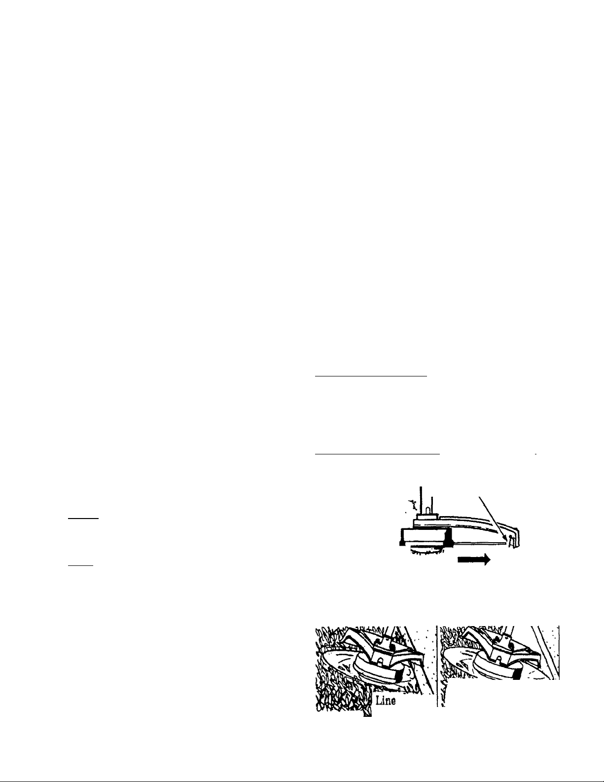
C. CUTTING METHODS
• The tip of the line does the cutting. You vnll
achieve the best performance and minimum line
wear by not crowding line into cutting area. The
right and wrong ways are shown in
t For frimming OF ica|
throttle to increase
ше less than full
espeelallyt
- during light duty cutting.
— near objects around which the line can wrap
such as small posts, trees or fence wire.
Crowded Into
WRONG Work Area
3 Inches I
Above
Ground
RIGHT
Tip of the
Line Does
The Cutting
17
Page 18
• The line will easily remove grass and weeds
firom around walls, fences, trees and flower
beds, but it also can cut the tender bark of
trees or shrubs and scar fences. To help avoid
damage especially to delicate vegetation or trees
with tender bark, shorten line to 4—5 inches and
use at less than full throttle.
• For mowing or sweeping, use full throttle for
a good clean job.
Use minimum speed and do not crowd the line
ik WARNING ^ ■■
when cutting around hard objects (rock, ^avel,
fence posts, etc), which can damage the trimmer
head, become entangled in the line, or be
thrown causing a serious haasard.
.
....
.
3 Inches
Above Tip of the Line
■ Ground ^ Does the Cutting
Always wear eye protection. Never lean over the
trimmer head. Rocks or debris can ricochet or
be thrown into eyes and face and cause blind
ness or other serious injury.
1. TRIMMING- _ Hold bottom of the
trimmer head about 3 inches above ground and at
: an angle. Allow only the tip of the line to make
contact. Do not force trimmer line into work area.
2. SCALPING - The scalping tech
nique removes unwanted vegetation. Hold the
bottom of the trimmer head about 3 inches above
the ground and at an angle. Allow the tip of the
line to strike CTOund around trees, posts, monu
ments, etc. This technique increases line wear.
3. MOWING- Your trimmer is ideal
........
for mowing in places conventional lawn mowers
cannot reach. In the mowing position, keep the
line parallel to the ground. Avoid pressing the
head into the mround as this can scalp the ground
and damage the tool.
4. SWEEPING- Thefanningaction
of the rotating line can be used for a quick and easy
clean up. Keep the line parallel to and above sur
faces being swept and move tool from side to side.
____________________________
D.LINE REPLACEMENT
• For proper line feed;
Une welding, and improper line feed.
A WABNING
To Remove, Turn Lock Ring Counterclockwise
To Replace, Turn Lefck Ring Clockwise
/1 ' ' ^ Y \ /no; \ ^ .'
Lock Tab
18
— Pre-wound spools offer the most conven
ient method for replacing line as well as
optimum performance.
• Always clean dirt and debris from spool and
hub when performing any type maintenance.
1. Installing Spool with Line
a. Hold the trimmer head as shown in ^
Press the lock tab and turn the lock ring
__________
1. ^ ' /
b. Remove the lock ring, tap button, and spool.
c. Clean dirt and debris from all parts.
d. Inspect all trimmer head parts for damage. Re
place damaged parts.
Awaking'................."
Trimmer head parts that are chipped, cracked,
broken, or damaged in any other way can fly
apart and cause serious injury Do not use. Repface damaged parts before using the tool.
.....
" '
Tap
Button
Lock Ring
Page 19
NOTE: The aluminum line saver can become —
worn during use. After a groove is worn
into line saver, remove it from trimmer head, turn
it upside down, and reinstall it {with'spool re
_____
moved) to provide a new wear surface.
Awahning
The line saver must be installed only from the in
side of the trimmer head. If installed on the out
side of the trimmer head, the line saver can fly
off and become a dangerous missile.________________
e. Insert the end of the line through the line saver.
Place spool in trimmer head. Press spool
down, then turn it enough to lock lugs on
spool under lugs on drive gear.
NOTE; Make sure the line is not caught between
the rim of spool and the wall of trimmer head.
f. Replace the tap button. Align the lock ring
over the catches on the hub; push the lock ring
down on the hub and turn it clockwise until the
catches lock into place.
_______
A WARNING
All catches must be fastened and the lock tab
latched in the Lock Ring. If installed incor
rectly, the Lock Ring can fly off and become a
dangerous missile.
g. Make sure lock ring is properly fastened by
pulling on it and trying to turn it counterclock
wise. If it comes off, reinstall it properly.
h. Pull on the line to change the spool from the
locked position to the operating position.
i. Obtain the correct line length (4-6 inches) by
pressing the tap button and pulling on the
line again.
NOTE; Each time the tap button is pressed, ap
proximately 2 inches of line can be pulled from
the trimmer head.
2. Spool Replacement
a. Replace the spool when the square comers on
the lugs are rounded off, reduced in size, or bro
ken off.
b. To replace the spool, follow the instructions in
“Installing Spool with Line.”
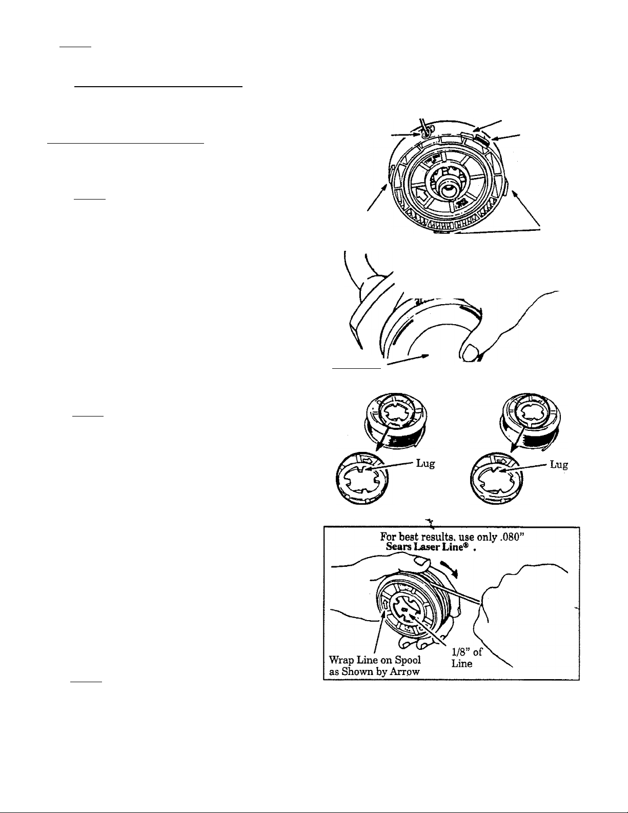
3. Installing Line on Spool
To replace the Line on existing Spool;
a. Follow “Installing Spool w/Line,” steps
“a.—d." and remove any line remaining on
the spool.
b. Use a 40 foot length of .080” Sears Laser Line.
e. Follow “Installing Spool with Line,” steps
If the line breaks off or backs up in the trim
mer head, follow “Installing Spool' w/Line,”
steps “a.—d.” Pull slack in line until the line is
tightly wound on the spool, leaving 4-~6 inches of
extended line. Continue with steps “e.~i.”
Catch
Line Saver
Catch
Approximately 2 Inches of Line Can
Be Pulled From the Trimmer Head
Each Time the Tap Button is Pressed.
Tap Button
NORMAL
SPOOL,
Lock Tab
Catch
WORN
SPOOL
c. Insert 1/16” to 1/8” of the end of the line
through the hole in the spool.
Allow no more than 1/8” line to extend in
side the spool.
d. Wrap the line onto the sjiool firmly and
evenly in a clockwise direction as shown by
the arrow on the spool.
NOTE; The line must be wrapped firmly and
evenly for proper line feed.
4. Trouble Shooting the Trimmer Head and Line
• Doei not advance/brealu while cutting} • Weldi onto apooli
- Improperly wound onto spool. — Line size incorrect.
Line elzo incorrect. - Incorrect ipool
- Too little line outside head. - Crowding line against material being cut.
• Pulls back into head: - Cutting at higher speeds than necessary.
- Too little line outside of head, • - -
19
Page 20

ACCESSORIES
The following accessories are available through Sears Retail Stores, Catalog, Outlets or Service Centers.
ITEM STOCK NO.
Safety Face Shield ..............................................................
Safety Goggles
2-CycIe Engine Oil
Spark Plug
Replacement Weed Blade
Replacement TVimmer Head (available only through Sears Service Centers) ............. . .952-701643
Replacement .0iS0"Dia. Nylon Trimmer Line
-400ft........................
.— 200 ft.
-100 ft.................
Replacement Spool with Line
Shoulder Strap Kit
Spark Arrestor Kit
Flex Shaft Lube...........................
...
...................
........................................
....................................
...........................................................................................................71-85608
............
................
.......................................................................
......................................................
......
............................
...
................
.............
.....
.....................................................................................
*AvailabIe through your SEARS SERVICE CENTER/CATALOGUE.
.........................
..............................................
.................................................................................
...........................................
...........................................
.............................
............
...........................
............................................................................. 71-85735
...................
...............................
...............................................................530-0301021.
......................
............................................... 71-30143
71-85854
......
........
........................... .71-85778
.............71-85771
.....................................
..................... ...........
.. 952-701612*
..................
..........
9-18613
71-85815
71-85783
NOTES
20
Page 21

CUSTOMER RESPONSIBÌLITIES
A. MAINTENANCE SAFETY
1. Maintain the tool according to recommended pro
cedures. Keep the blade sharp and the cutting line at the pro
per length.
2. Never start the engine with the clutch shroud
removed. The clutch can fly apart and cause serious
injury.
3. Disconnect the spark plug before performing
maintenance except for carburetor adjustments.
4. Make carburetor adjustments with the drive shaft hous
ing supported to prevent the blade or trimmer line from
contacting any object. Hold the tool 1^ hand; do not use the
shoulder strap for support.
5. Keep others away when making carburetor
adjustments.
FLEXIBLE DRIVE SHAFT UIBBICAIION
• Lubricate the Flexible Drive Shaft:
- After each ten (10) hours of operation.
- Before operating If the tool has been
stored for 90 days or longer.
• When ordering flex shaft lube, see the
Accessory List for proper part number.
A WARNING
If engine has just been operated, avoid touching
the muffler. A hot mumer can cause serious
bums.
6. Be sure blade or trimmer head stops turning when
engine idles. See “Carburetor Adjustments.”
7. Wear protective gloves when handling or performing
maintenance on the blade.
8. Throw away blades that are bent, warped, cracked, ;
broken,ordamagedinanyotherway.Replacetrim- i
merheadpartsthatarecracked,chipped, broken,
or damaged In any other way before using the tool.
9. Use only .080" diameter Sears Laser Line. Never
use wire, rope, string, etc.
10. Useonlygenuinereplacement partsasrecommended by Sears.
11. Inspect the entire tool. Replace damaged parts. Check
for fuel leaks and make sure all fa.steners are in place
and securely fastened.
6. Apply a uniform coat of lube to the entire sur
face of the flexible drive shaft.
7. Inject the remaining contents of the tube into
the top of the tube.
8. Replace flexible drive shaft in the tube.
9. Reassemble the gear box to the tube. Tighten
screws securely.
j
CAUTION; I Lay the flexible drive shaft on a
clean surface. Avoid laying the shaft on the
floor, ground or on any other surface that
may have dirt or debris. Even after wiping
the shaft, grease residue can pick up diif
particles that can cause damage or prema
ture failure.
I CAUTION: I Take care to avoid im'ury to your
hands and fingers with broken wires when
checking for damage or wdping the flexible
drive shaft. A cloth will not prevent broken
wires fl'om puncturing or tearing your skin.
1. Remove the gear box clamp screw and the lo
cating screw from the gear box.
2. Remove the gear box from the tube.
3. Remove the flexible drive shaft from the tube.
4. Check flexible drive shaft for broken wires,
twists or kinks, and replace if damage is found.
5. Using a clean cloth, wipe surface of flexible
drive shaft thoroughly to remove any grease.
21
Page 22

C. CjysmiMirroilAPJUSTMiacri
▲warming
Make caiiNiretora4justnieiits with the drive shaft hous*
_____
ing supported to prevent the Blade or trimmer line
from contacting any object.Hold the tool with yourhandi
do not use theoptional shoulder strap for support.
▲warning
Keep others away when making carburetor
adjustments.
- “ follow the instructions. The basic carburetor settings
are provided in the event they are required.
a. Turn the Low Speed Mixture Screw and the High
Speed Mixture Screw clockwise until they stop.
Do not turn the screws until they are tight as
damage to the needle seats can occur
b. Turn the Low Speed Mixture and High Speed Mix
ture Screws one full turn countercloclwise.
c. Follow instructions “a. Preparation,” through “f. !
High Speed Mixture Adjustment.”
▲warning
Serious Injury to the operaUir and others can occur if the
carburetor is not properly adjusted.
• Poor engine performance can be a result of other
causes such as dirty air filter, carbon build-up
on muffler outlets, etc. See “TVouble Shooting
Chart” before proceeding with carburetor
adjustments.
• The carburetor has been carefully adjusted at the
factory. However, the operator must be sure that
adjustments are made when any of the'conditions
occur as mentioned In “Trijuble Shooting Sugges
tions” below.
• Very small adjustments can affect engine perfor
mance. It is important to turn the screw a very small
amount per adjustment and test performance before
making further adjustments. Each adjustment should
be no more than the width of ihe slot in the adjusting
screws.
• This is a complicated task. It Is important to follow
Instructions in sequence as indicated.
1. mOUBLE SHOOTING SUGGOTIONS
— Engine will not continue to run at idle position.
See “b.” Idle Speed Adjustment” and “e. Low
Speed Mixture Adjustment.”
— Blade or Trimmer Head continues to spin when
the engine idles. See “b. Idle Speed Adjustment”
and “d. Deceleration Check.”
— Engine dies or hesitates when it should accelerate.
See “c. Acceleration Check.”
— loss of cutting power which cannot be corrected
by cleaning the air filter. See “f. High Speed Mix
ture Adjustment.”
— Engine does not return to idle from full throttle
within 2 seconds. See ‘‘d. Deceleration Check.”
— Engine will not run. See “TVouble Shooting
Chart.” Then, if the carburetor requires adjust
ment, begin with“2. Basic Carburetor Settuip.”
▲warning
.....
The Blade or trimmer line will be spinning during
most of this procedure. Wearyour protective equipment
and observe all safety instructions. __________________
l.BA81CCAIUItmif01ttETnN0S
NOTE; In most cases, your engine can be made to
ran properly with minor carburetor adjustments.
Refer to “Trouble Shooting Suggestions” in the left
column for the condition you are experiencing and
22
3.PROCEDUR£
a. PREPARATION
1. jUsea fresh fuel mix. See “FuelingTtburEngine."
2. )Mal« sure line extends to the length allowed by line
limiter to provide correct load on engine.
3. jStart the engine. Cut grass for 3 minutes to warm
engine. The engine must be at operating temper
ature before carburetor adjustments can be per~
formed correctly.
4. )Stop engine and remove air filter pulling it out
with your fingers. Refer to “Specifications” for
location.
tx IDLE SPEED ADJUSTMENT
1. jAllow engine to idle.
2. )Adjust Idle Speed Screw until the engine
continues to run without stalling and
without the trimmer head moving.
—^ Turn screw clochme to increase engine speed
if the engine stalls or dies.
— Turn screw counterclockwise to slow engine
dorni and/or to keep blade or trimmer head
from turning.
3. )FoIIowinstructionsin ”c. Acceleration Check”
and “d. Deceleration Check.” .
4. )No further adjustments are necessary if the
trimmer head does not turn at idle speed and
If performance is satisfactory.
¿Warning
Recheck idle speed after each adjustment. The blade or
trimmer head must not turn at idle speed to avoid serious
injury to the operator and others. ___________________
«.ACCELERATION CHECK
1. jAllow engine to idle. ^
2. }Squeeze Trigger fully
a. If performance Issatisfactory, proceed to “d.
Deceleration Check."
b. Ifthe engine does not accelerate smoothly,
turn the Low Speed Mixture Screw counter-
clockwise a small amount (no morei than the
widthofthesiot intheadjustingserew).
_
3. )Repeat step “2.)” until smooth acceleration is
obtained,
NOTE: It may be necessary to repeat “b. Idle
Speed Adjustment” through “c. Acceleration
Check,” to obtain correct adjustments.
4'.)FoIlow instructions in “d. Deceleration Check ."
___________
Page 23

d. DECELERATION CifEGK
1. ) Allow engine to idle, then squeeze Throttle Trig
ger fully.
2. )Allow engine to run at full speed for about 1
second.
3. )Release the Throttle Trigger to the idle position
and listen to the deceleration of the engine. It must
return to idle smoothly and within ! to 2 seconds.
a. If performance is satisfactory,«proceed to
Step "4.)”
b. If the engine slowly or erratically returns to
idle or idles erraticaUy, repeat “b. Idle Speed
Adjustment” or continue through Low Speed
Mixture and High Speed Mixture Adjustments
to obtain proper deceleration.
4. jRecheck idle speed.
luOT SPEE0 MIXTURE ^ ""
ADJUSTMENT SCREW LOW SPEED MIXTURE
IDLE SPEED
ADJUSTMENT
SCREW
ADJUSTMENT SCREW
AIR
FILTER
COVER
c. U»WSPlEDMlXTlIll£AD|USTMfiNT
1. jAIlow engine to idle.
_____
2. Turn the Low Speed MixtureSciew slowly
clockwise until the speed starts to drop.
Note this position.
3. ) Tum the Low Speed Mixture Screw counter
clockwise until the speed increases and then
starts to drop again. Note this position.
4. )Set the Low Speed Mixture Screw at the mid
point between the two positions.
5. )Follow instructions in “c. Acceleration Check"
and “d. Deceleration Check.”
f. HIGH SPEED MIXTURE ADJUSTMENT
I CAUTION; I Do not operate engine at full
throttle for prolonged periods while making high
speed adjustments as damage to the engine
can occur.
1. jSupport the drive shaft housing so the trimmer
line is off the ground and wili not make contact
with any object.
2. )Allow engine to idle, then squeeze Throttle Trig
ger fully.
NOTE: Perform steps ”3.)” through ”5.),”
at full throttle.
............
..................... .............
3. ) Turn High Speed Mixtare Screw \ery slowly
clockwise until engine speed is reduced,
4. )Turn High Speed Mixture Screw very slowly
counterclockwise. Stopwhentheenginebegins
to run roughly.
5. jTlim the screw slowly the minimum amount
clockwise until the engine runs smoothly.
6. ) Follow instructions in “c. Acceleration Check”
and “d. Deceleration Check.”
' [CAunoNTl If the engine does not operate
according to these instructions after repeating
the adjusting steps, do not use the tool. Take
it to your Sears Service Center.
g. REINSTALL AIR FILTER
Be sure filter is clean. See “Air Filter" for
instructions.
I CAUTION; i Fit air filter into the corners of the
housing to keep dirt from entering the engine and
causing engine damage. ' .
D. SmBXCRROPE
Adanger
Never start the engine with the clutch shroud removed.
The clutch wi^ fly apart and cause serious injury.
ikWARmNG
Do not remove the retaining tab and screw to remove
pulley. The spring beneath the pullQ' is under tension
and can fly out causing serious injury. If any part of the
PuUq'hoiKing assemHy is damaged other than the rope,
do not use the tool. Ikke it to your Sears Service Center.
Disconnect Spark Plug Wire.
1.
Remove the Screw and Nut in the Throttle Trigger
2.
Housing. Hold the Throttle Trigger away fiom Drive
Shaft Housing and remove Throttle Cable from
Trigger. Pull Cable out of Foam Grip
tunnel.
RemcA'c the four Clutch Shroud Screws m shown in
3.
with ihe^fiiali hex Wfefleh pfevlded.
4.
Separate the Clutch Shroud tom the Engine.
Adanger
Use only ahandUiol to remove the clutch. Donotuseany
typeofmotormdtoolbrsirikedtedtUchinanyway. Otker-
wise, the clutch will fly apcai and cause serious injury.
.............
REMOVE SCREWS
Shown without Drive Shaft
Housing for clariU'.
CLUTCH “FLATS”
SPARK
PWQ
ШЁ
CLUTCH
SHROUD
23
Page 24

5. Hold the “Flats” of the Clutch with an adjustable
wrench as shown in Figures and remove the Nut
counterclockwise with a 9/16" socket wrench,
NOTE; Clutch will slide off the crankshaft intact. Do
not disassemble dutch.
6. Remove the Beveled Washer, Clutch an^ Large Flat
Washer. _ __
7. Remove the Pulley Housing from the Engine.
_____
8. Remove Rope Retainer Screw. Remove any
remaining rope.
9. Hand turn the Pulley clockwise asfer as it will go. Then,
turn the Pulley counterclockwise until the Pulley
Notch is aligned with the Housing Notch next to the
Retaining Tab and Screw. Next, turn the Pulley one
complete turn counterclockwise until the notches are
aligned again.
________
__
10. Insert the small hex wrench into the hole formed by
the Notches to hold the Pulley in position.
__________
11. Use a42 "length of replacement Rope.
12. Moveaway (10 feet) from the fuel tank with the replace
ment Rope. Use a match and melt both ends of the Rope
to prevent haying.
13. Pull the melted ends through a thick, clean rag while
the Rope is still hot to obtain smooth, pointed ends.
14. Insert one end of the Rope through the Handle and
secure with a knot.
15. Insert the other end of the Rope through the Rope Exit
Hole into the inside ofthe Housing, into the Pulley and
up through the Pulley Hole.
16. Wrap Rope counterclockwise around the Pulley Ratchet
and tuck loose end under Rope where it comes out of
the PuIIq? Hole. Leave a 1-inch tail l^ing flat on top of
ÛiePull^betweentheRetainerRibandtheRopeRetention Screw/Post.
...
............................
17. Reinstall the Rope Retention Screw into the reten
tion post. Tighten until snug.
NOTE; Do not overtighten the Screw. Overtightening
the screw can cause the threads in the screw post
to strip out.
18. Hold Rope taut at Rope Exit Hole so it will not move and
remove hex wrench.
19. Slovvly feed rope into the Pulley Housing.
_____
20. Make sure Spacer is in place as shown then reverse
steps to re-assemble,
_________
Rope
Retainer Screw
Washer
Rope Tail '
24
I CAUTIOmTI WhenreinstalUngtheclutch, tighten
the nut just until the beveled washer is flattened
against the clutch. Over or under tightening the nut
can cause engine damage.
Page 25

_1. AntnilfEE . • ■
......
NOTE: A dirty air filter decreases the life and
performance of the engine and may incre£ise fuel
consumption and harmful emissions.
1. Clean the Air Filter;
• Always after 5 tanka of fuel or 5 hours of
operation, whichever is less.
• More frequently, in dusty conditions.
a. Loosen the two screws on the air filter cover
enough to remove the cover from engine.
b. Remove the air filter from the cover.
c. Wash filter in soap and water.
d. Squeeze filter dry and replace in cover.
I CAUTIÒn7Ì Do not clean the air filter in gaso
line or any other flammable solvent; &ing
so may create a fire hazard or produce
harmful evaporative emissions.
e. Reinstall the air filter cover, making sure
the choke exit slot is placed over the choke
lever.
^AUTIONTI Make sure the air filter is fitted
'**•*-'*■ *~^ * ^■ -* 4k.JiVVV.>U
gihedamage.
iiito the comers of the coyer to keep dust
from entering the engine and causing en-
........
....
....
............
..................
NOTE; If replacing the air filter, see the
Accessory List for proper part number.
................
Choke
- Exit Slot
Air
Filter
Choke
Air Filter
Cover
Corners
.......
F. BUiDE SHARPEMING
A WAKNMG
engine stops or after the throttle trigger has
been released. Make sure the blade has stopped
coasting and disconnect spark plug befoz« per
forming work on blade.
1. The blade is reversible, 'l^en the cutting ed^
on one side becomes duU, turn the blade over,
l^eh both sides of cutting edges become dull, the
blade may be resbarpeneo.
2. Check blades for flatness petdodicaHy. Lay
the blade on a flat surface and inspect the blade for
flatness before sharpening. Throw away a blade
that is not flat.
3. File or grad each edge in the same manner
to maintain a balanced blade. .
A WARNDIG
Always replace a blade that is bent, warped,
cracked, broken, or damaged in any other way.
Never attempt to straighten and re—use a dam
aged blade. Use only the specified replacement
blade. '
J CAUnON; I Wear protective ^oves when
handling or performing maintenance on
the blade to help avoid injury.
_________________
________
' '
'
_________
A WAHNING
To prevent the blade from cracking or flying
apart after sharpening, do not file within 1/4
inchof the radii shown in Figure 26.
File or Grind Each
Edge in the Same
Manner to Maintain
a Balanced Blade.
□
1/4 Inch
..,^1 Maintain Radius
Maintain Radiusr
Sharpen This
Ary Only
y
NOTES
25
Page 26

STORAGE
Immediately prepare your unit for storage at the end of the
season or if it will not be used for 30 days or more.
WARNING:
A
GAS TRIMMER/BRUSHCUTTER STORAGE
INSTRUCTIONS
If your trimmer/torushcutter Is to be stored for a period of
time, clean it thoroughly prior to storage. Remove any
dirt, sawdust, leaves, oil, grease, etc. Store in a clean dry
area. '
• Clean the entire unit.
• Clean air filter. Refer to “Customer Responsibilities".
• Open the line head assembly and clean any dirt, grass or
debris that has collected. Inspect the cutting line, if old
(chalky look and sticky to the touch), remove and dis
card. Install fresh new line the next time product is to be
used.
• Lightly oil external metal surfaces to prevent rust from
forming.
A
If your unit is equipped with a blade, remove it from the
unit. Refer to “AssembI/'. Apply a coating of oil to the
entire surface of the blade and wrap it in heavy paper,
cloth, or plastic. Also apply a light coat of oil to gear hous
ing threads, then tighten blade nut securely for storage.
Reassemble all loose parts, being sure that all handles
and guards are in place and are securely fastened. Re
place any damaged parts.
ALLOW THE ENGINE TO COOL, AND SE
CURE THE UNIT BEFORE STORING OR
TRANSPORTING IT IN A VEHICLE.
STORE UNIT AND FUEL IN AN AREA
WHERE FUEL VAPORS CANNOT REACH
SPARKS OR OPEN FLAMES FROM WA
TER HEATERS, ELECTRIC MOTORS OR
SWITCHES, FURNACES, ETC.
STORE UNIT WITH ALL GUARDS IN
PLACE. POSITION SO THAT ANY SHARP
OBJECT SUCH AS BLADES CANNOT
ACCIDENTLY CAUSE INJURY TO PASS
ERS BY.
STORE THE UNIT OUT OF THE REACH
OFCHILDREN.
CAUTION; Wear protective gloves when
handling blade. The blade Is sharp and
can cut you even when It Is not moving.
ENGINE
Never use engine or carburetor cleaner products in the fuel
tank or permanent damage may occur to fuel system com
ponents.
Follow these instructions:
a. Drain the fuel from the unit into an approved
fuel container.
b. Drain the fuel lines and carburetor by starting
the engine and letting it run until it stops.
. c. Allow the engine to cool before storage.
IMPORTANT: It is important to prevent gum deposits from
forming in essential fuel system parts such as the carbure
tor, fuel filter, fuel line or tank during storage. Also, experi
ence Indicates that alcohol blended fuels, those that use
ethanol or methanol (called gasohol or oxygenated fuel),
can attract moisture and form acidic gas which will damage
your engine. To avoid engine problems, the fuel system
should be emptied before storage of 30 days or longer.
NOTE; Fuel stabilizer is an acceptable alternative in mini
mizing the formation of fuel gum deposits during storage.
Add stabilizer to the gasoline in the fuel tank or fuel storage
container. Always follow the mix instructions found on stabi-
llzer container. Run engine at least 5 minutes after adding
stabilizer to allow the stabilizer to reach the caiburetor.
NOTE: Craftsman 40:1 2-cycle engine oil is specially
blended with fuel stabilizers. If you do not use this SEARS
oil, you can add a fuel stabilizer (such as Craftsman #33500)
to your fuel tank.
• Remove spark plug and pour 1 teaspoon of 40:1 oil mix
through the spark plug opening. Slowly pul! the starter
rope 8 to 10 times to distribute oil to inner engine sur
faces. ’ ‘
• Replace spark plug with a new one of the recommended
type and heat range. Refer to “Product Specifications".
• Clean air filter. Refer to "Customer Responsibilities".
• Reinstall all covers-and hardware removed for access:
tighten all screws arid fasteners.
• Check entire unit for loose screws, nuts, and bolts. Re
place any damaged, broken, or worn parts.
• Use fresh fuel having the proper gasoline to oil ratio at the
beginning of the next season.
OTHER
• Do not store gasoline from one season to another.
• Replace your gasoline can if your can starts to rust. Rust
and/or dirt in your fuel system will cause problems.
• Store your unit in a well ventilated area and covered, if
possible, to prevent dust and dirt accumulation. Do not
cover with plastic. Plastic cannot breathe and will induce
condensation and eventual rust or corrosion.
IMPORTANT; Never cover unit while engine and exhdust
areas are still warm.
26
Page 27

TROUBLE SHOOTING CHART
SYMPTOM CAUSE
Engine will not
start or will run
only for a few
seconds after
starting.
Engine will not
idle properly
Engine will not
accelerate,lacks
power, or dies
under a load.
Engine
smokes
excessively.
Engine runs hot.
Cutting Head stops
under a load or
does not turn
when engine is
accelerated.
Line does not
advance or breaks
while cutting.
Line welds on spool.
1. Fuel tank empty.
2. Engine flooded.
3. Spark plug not firing.
4. Fuel not reaching carburetor.
5. Carburetor requires adjustment,
6. None of the above.
1. Carburetor requires adjustment
2. None of the above.
1. Air filter dirty.
2. Spark plug fouled.
3. Carburetor requires adjustment.
4. Muffler outlets plugged.
5. None of the above.
1. Air filter dirty.
2. Fuel mixture incorrect.
3. Carburetor requires adjustment.
1. Fuel mixture incorrect.
2. Carburetor requires adjustment.
3. Spark plug incorrect.
4. None of the above.
1. Drive shaft broken.
2. Drive shaft not engaged.
1. Line improperly routed in head.
2. Line improperly wound onto spool.
3. Line size incorrect.
4. Too little line outside head.
5. Dirt accumulated on cover cut-outs.
1. Line size incorrect.
2. Crowding line against material being cut.
3. Cutting at higher speed than necessary.
REMEDY .
1. Fill tank with correct fuel mixture
2. See “Starting Instructions.”
3. Install new plug/check ignition system.
4. Clean fuel filter; inspect fuel line.
5. See “Carburetor Adjustments.”
6. Contact your Sears Service Center/Dept,
1. See “Carburetor Adjustments.”
2. Contact your Sears Service Center/Dept,
1. Clean or replace air filter.
2. Clean or replace spark plug and re—gap.
3. See “Carburetor Adjustments.” .
4. Contact your Sears Service Center/Dept.
5. Contact your Sears Service Center/Dept,
1. Clean or replace air filter.
2. See “Fueling Your Unit.”
3. See “Carburetor Adjustments.”
1. See “Fueling Your Unit.”
2. See "Carburetor Adjustments.”
3. Replace with correct plug.
4. Contact your Sears Service Center/Dept.
1. Replace drive shaft.
2.. See “Assembly”.
1. Remove cover. Check line routing,
2. Rewind line tightly and evenly.
3. Use only .080” (2mm) diameter Sears Laser
Line,
4. Remove cover. Pull 4” of line to outside..^
5. Clean cover cut-outs.
1. Use only .080,” (2mm) diameter Sears Laser
Line. -u
2. Cut with of line.
3. Reduce cutting speed.
Line releases
continuously.
Line usage is
excessive.
Line pulls back
into head.
1. Tap Button engaged.
2. Tap button knocked out of hub .
1. Line size incorrect.
2. Cutting at high speed around hard objects,
3. Crowding line against material being cut.
• Too little line outside of head.
1. Remove and clean Tap Button.- -
2, See “Installing Spool w/Line.”
1. Use only .080” (2mm) diameter Sears Laser
Line. . ^'
2. Reduce speed around hard objects.
3. Cut with tip of line.
• Remove cover. Pull 4” (10 cm) of line to
outside.
27
Page 28

INDEX
ACCESSORIUS
ADJUSTMENTS
Handlebar
Carburetor
l.inc Advance
Module Air Gap.............................................................2
Spark Plug Gap........................................................ 2
Shoulder Strap..............................................................10
Throttle Cable
AIR FILTER....
ASSEMBLY
Blade..............................................................................9
Clamp, Shoulder Strap.................................................10
Handlebar.......................................................................7
Preparation.....................................................................6
Shield
Line Trimmer.............................................................. 8
Weed Blade................................................................. 9
Shoulder Strap
Throttle Cable................................................................7
Trininier Head................................................................8
Weed Blade
BLADE, WEED
Cutting Methods.......................................................... W
Guard Against Blade Thrust........................................15
...
..................................................................................
Safety.......................................................................... 71
Sharpening...................................................................25
CARBURETOR ADJUSTMENTS
CARTON CONTENTS
COLD ENGINE STARTING
CONTROI-S..........................................................................2
CUTTING METHODS
Weed Blade.................................................................. 1^
Line Triinnicr...............................................................18
DRIVE SHAFT HOUSING ASSEMBLY
ENGINE
Air Filter
Carburetor
Controls.......................................................................... 2
Fuel Mixture................................................................11
Starter Rope
Starting In.stnictions
Storage
Trouble Shooting
ENGINE OIL
Ratio to Gasoline.........................................................11
Types to Use: not to Use
FILTER, AIR.......................................................................25
FLEXIBLE DRIVE SHAFT LUBRICATION
FUEL
Gasoline/Oil Mixture
Mixing Fuel..................................................................j j
Pouring Fuel
Storage.........................................................................11
GASOLINE
Ratio to Oil
Type to Use; not to Use...............................................11
IDLE SPEED AD.IUSTMENT
LINE
Advance........................................................................*'
Length
Operation.............................................................
To Cut as Replacement............................................--20
Replacement
Hdwimling tin Spool....
Routing in Head...........................................................19
Safety............................................................................ 9
Size to Use....................................................................
Tituthle Sliuntiijy.................................................. ••“Il
Welding onto Spool......................................................-o
...................................................................
......................................................................
....................................................................
..................................^............................
..............................................................
.................................................................
.............................................................
...................................
-.................................9
....................................
........................................................
.............................................
...........................
.................................................................
••25
....................................................................
................................................................
....................................................
.........................................................................
.........................................................
..............................................
..................
....................................................
.................................................................. ' ‘
..................................................................11
..........................................
.............................
............
...................
............................................................
........................
25
19
20
7
22
17
7
10
75
22
5
12
6
22
23
12
"4
26
11
21
i
22
..20
19
LUBRICATION
Engine....................................................................................11
Flexible Drive Shaft.............................................................21
MAINTENANCE
Air Filter.............................................................................. 23
Blade, Weed..........................................................................25
Carburetor
Flexible Drive Shaft.............................................................21
Safety.....................................................................................21
Starter Rope......................................................................... 23
Trimmer Head......................................................................19
Trouble Shooting Chart.......................................................26
MODULE AIR GAP...
OIL, ENGINE
Ratio to Gasoline..................................................................11
Types to Use; notlo Use........................................................11
OPERATION
Advancing the Line
Mowing
Pre-Operation Checks
Position
Safety
Blade
Line Trimmer....................................................................17
Scalping
Starling the Engine...............................................................12
Speed..,...................................................................................13
Stopping the Engine
Sweeping
Trimming...............................................................................18
Weed Blade............................................................................16
PA RTS I I<«T 27
PRE-OPERAflON‘CHECks"IIII!IIIIIII"*;^^
PREWOUND SPOOLS................................................................19
REPAIR PARTS LIST.................................................................27
SAFETY INSTRUCTIONS, WARNINGS
SHIELD
Line Trimmer Assembly........................................................8
Blade Assembly.......................................................................9
SHOULDER STRAP CLAMP ASSEMBLY
SHOULDER STRAP..........................................................>.........10
SPARK PLUG GAP
SPARK ARRESTOR
SPECIFICATIONS....................................................................... 2
SPOOL
Installation
Maintenance..:^....................................................................19
Rewinding
STARTER ROPE REPLACEMENT
STARTING INSTRUCTIONS
STORAGE
THROTTLE CABLE ASSEMBLY..............................................7
TRIMMER HEAD
Assembly
Line Routing
Maintenance..........................................................................19
Removal
Safety
Shield.......................................................................................8
TROUBLE SHOOTING CHART..............................................
USING YOUR TOOL AS A WEED CUTTER
USING YOUR TOOL AS A LINE TRIMMER
WARM ENGINE STARTING
WARM ENGINE STARTING AFTER RUNNING
OUT OF FUEL................................................................... -12
WARNINGS AND SAFETY INSTRUCTIONS
WARRANTY,,...-..,
WEED BLADE ASSEMBLY
............................................................................
.............
.......................................................2
..........
..................................................................................
..................................................................................
..................................................................................18
................................................................................
.............................................................................
.......................................................................................
................................................................................
................................................................................19
..........................-..........................................................
..............................................................17
.........................................................................18
...........................................................................
.......................................................................
..........................................................12
............................................................
............................
.............................
.......................................................................
............................................-..................
.........................................
.......
..............................................12
.........................
........................
....................................................
..................
........
...........
........................................................
......................
3 & 4
^••-5
3 & 4
22
10
15
12
10
"19
18
2
19
20
23
4
-8
12
26
14
16
12
.
9
Page 29

The Model Number will be found below the top handle with the Serial
Number. Always mention the Model Number when requesting service or
repadr parts for your unit.
All parts listed herein may be ordered from any Sears Service Center
and most Sears Stores.
Operator’s
Manual
Model No.
3Sa798260-32cc
How to Order
Repair Parts
WHEN ORDERING REPAIR PARTS ALWAYS GIVE THE FOLLOWING
mPORMATION AS SHOWN IN THIS LIST:
1. The PART NUMBER
2. The MODEL NUMBER
3Sa798260
If the parts you need are not stocked locally, your order will be trans
mitted to a Sears Repair Phrts Distribution Center for handling.
3. The PART DESCRIPTION
4. The NAME OF ITEM —
32cc Gas Weedwacker®
When you buy merchandise from
Sears you get an extra value that
nobody else can offer — Sears
Service.
Across town or across the country,
Sears Service is always near, pro
viding trustworthy, competent
service technicians using only
Sears specified factory parts.
SEARS SERVICE
IS AT YOUR SERVICE
Sears, Roebuck and Co,, Hoffman Estates, ÏL 60179 U.S.A.
Your Sears Merchandise takes on added value when you discover
that Sears has Service Units throughout thé country. Each is
staffed by Sears-Trained, professional technicians using Sears ap
proved methods.
PRINTED IN USA.
Page 30

ESTE MANUAL ES MUY IMPORTANTE
Manual del
operario
No lo tire a la basura
MODELO NO.
358.798260-32CC
A PELIGRO:
Lea el manual del operario y
siga todas las advertencias e
instrucciones de seguridad y las
instrucciones para la
operación. El no hacerlo puede
causarle lesiones graves.
Use siempre protección para los ojos
SEAR^/CI^RFTSMnN
CORTADORA DE HIERBAS
WEEDWACKER® A GASOLINA DE 32cc
Motor de 2 tiempos
• Armado
• Operación
Mezcla de combustible 40:1
• Mantenimiento
• Piezas de repuesto
530-082426-1-04/12/94
Sears, Roebuck and Co., Hoffman Estates, IL. 60179 EE.UU.
© 1994 Sears, Roebuck & Co.
Page 31

GARANTIA LIMITADA DE DOS AÑOS PARA LA CORTADORA DE HIERBAS "WEEDWACKER^ '''" CRAFTSMAN
Por dos anos desde la fecha de la compra, si esta Wéedwacker™ es mantenida, lubricada y afinada dé acuerdo con las instrucciones para
la operación y el mantenimienlo contenidos en el manual del operario, Sears reparará libre de cargo cualquier defecto en materiales o
manodc'obra-. ' v ^ ^ . . ■ a ' , ■ ■ . .
Esta garantía excluye la línea de nylon, la bujía y el filtro de aire que son piezas reemplazables y se gastan duránteel uso normal.
Si esta Weedwacker”“* es empleada para u.sos comercialc.s o para alquiler, esta garantía no se aplica.
EL SERVICIO DE GARANTIA ESTA DISPONIBLE PONIENDOSE EN CONTACTO CON EL CENTRO O DEPARTAMENTO DE
.SERVICIO SEARS MAS CERCANO EN LOS ESTADOS UNIDOS. Esta garantía se aplica solamente mientras e.ste producto está en
uso en los Estado.s Unidos.
Esta garantía le da a usted derechos legales específicos y usted puede tener otros derechos que varían de estado a estado.
...........
SEARS, ROEBUCK AND CO./DEPT. D/8I7WA, HOFFMAN ESTATES, IL 60179 EE.UU.
LISTA DE CONTENIDO
ADVERTENCIAS E INSTRUCCIONES
PARA LA SEGURIDAD .................
CONOZCA SU HERRAMIENTA
ARMADO.....
CARGANDO COMBUSTIBLE A SU MOTOR
ARRANCANDO SU MOTOR
..............
................................................................................6
..............................
....
...........................................
...........................;..............................
....................................
...
....... .......................
USANDO SU CORTADORA DE MATORRALES.
USANDO SU CORTADORA
3
5
11
12
COMO CORTADORA DE LINEA...........
ACCESORIOS;......
RESPONSABILIDADES DEL OPERARIO
INDICE
...................................................................................
...............
.il;..;';..................:!'....
.................
...........
......................
.14
...16
...20
...21
...зГ
ESPECIFICACIONES
TIPO DE MOTOR
DESPLAZAMIENTO 32ec
RPM DEL MOTOR Operación: 7500
ENCENDIDO , Estado sólido
SINCRONIZACION Avance de chispa DEL ENCENDIDO Noajusttible
CARBURADOR Diíifragma. Todas las posiciones con
"APAGADO" DEL MOTOR
ARRANCADOR
SILENCIADOR
EMBRAGUE
TANQUE DE COMBUSTIBLE
LARGO DEL EJE
BUJIA
ABERTURA DE LA BUJIA
ABERTURA DEL
MODULO DE AIRE
LUBRICACION Mezcla de gasolina y aceite al 40; 1
LINEA PARA EL CORTE
HOJA
NOTA: "ÍAfim UNE " ES UNA MARCA DG GADRICA
REGISTRADA DE WHITE CONSOLIDATED INDUSTRIES. INC.
i-ABRICADA BAJO UNA O MA.S DI-. I.AS SICitm;NTI;.S PATKNTKS U, .S.;
4.052.7Xy; 4.112.M.4:4.1 hl .S20; 4.167.X 12:4.1 .S.J.i .18; ,4.Ì 4.211 ,(KM; 4.2X<1.675;
4,.V)2.»74:4.4.S 1,98.1; 4,79H,I8.S; 4,82.1.4().S; 4.841.929; 4.940.028; 5,t)2n,223: y D324.05I.
2 KSTAN PKNDIllNTl-S OTRAS PATRNTKS U. .S. Y DHL KXTKRIOR.
2 tiempos, enfriado por aire
En vacío: 2800 - 3200
surtidores de mezcla de combustible
regulables
Bolón para empujar
Recnrollado automático
Limitador de temperatura (sin
parachispas; vea NOTA en la página 6)
Centrifugo
17 oz. líquidas
51" (129.5 cm) ,,
7í-85854(CJ-14)
0.025"
0.010/0,014 .
Sears La.ser Line", diámetro 0.080"
Hoja puní hierbas de 4 puntos, 8"
Asa en "T" de la cuerda
para arrancar
Interruptor ~‘^j)j^x;embrague
del motor.
Número de serie e \
instrucciones para arrancar
Tapa de combustible
\
Estrangulador
llítmlliilil
para cebar
Correa para el hombro
Escudo
plástico
Vimitado/ Cabeza de
de la línea la cortadora
Cubierta del
filtro de aire ’
Silenciador y
cubierta del
silenciador
Bujía
МапиЬЛо
Etiqueta de .seguridad
/
/
Hoja para hier
con 4 diente.s
Page 32

A ADVERTENCIAS E INSTRUCCIONES PARA SEGURIDAD
(Lea las Instrucciones para seguridad adicionales a través de este manual)
A ADVERTENCIA: ¡ESTA HERRAMIENTA MOTORIZADA PUEDE SER PELIGROSA! Esta
herramienta puede causar lesiones graves a los operarios u otras personas, incluyendo amputaciones o ceguera. Las
advertencias e Instrucciones para la seguridad en este manual deben ser seguidas para proveer una seguridad razonable y
eUcicnciii en el uso de esta herramienta. El operario es responsable de seguir las advertencias e instrucciones contenidas en este
manual y en la herramienta. ¡Lea íntegramente el Manual del Operario antes d& armar y usar esta herramienta! Restrinja el uso de
esta lierratiiicnla motorizada a las personas que puedan leer, entender y seguir las advertencias e instrucciones contenidas en este
manual y cu la herramienta.
Apeligro
LA HOJA PUEDE REBOTAR VIOLENTAMENTE DEL
MATERIAL QUE NO PUEDA CORTAR.
—LA HOJA CIRCULAR DE SIERRA PUEDE
' REBOTAR Y CAUSAR LA AMPUTACION DE
PIERNAS O BRAZOS,
—MANTENGA A LA GENTE Y ANIMALES
ALEJADOS A 30 PIES (10 m) DE DISTANCIA.
Protectores para
la.s piernas
Máscara para Botas
el rostro
A ADVERTENCIA
LA LINEA DE LA CORTADORA PUEDE DISPARAR
OBJETOS VIOLENTAMENTE.
—USTED PUEDE QUEDAR CIEGO O LESIONADO.
\
A ADVERTENCIA
Zona de peligro
de 60 pies
(20 metros)
Detenga el desplazamiento de ^ ADVERTENCIA ^
la hoja mediante el contacto
i con el material cortado ^ DESPLAZA CUANDO SE DESCONECTA EL
—USE PROTECCION PARA LOS OJOS Y LAS
PIERNAS.
ZONA DE PELIGRO POR OBJETOS DISPARADOS.
—LA HOJA O LA LINEA DE LA CORTADORA
PUEDE DISPARAR OBJETOS
VIOLENTAMENTE.
—OTRAS PERSONAS PUEDEN SER CEGADAS O
LESIONADAS. '
—MANTENGA ALEJADAS A LAS PERSONAS Yv
ANIMALES A UNA DISTANCIA DE .30 PIES
(10 METROS).
ACELERADOR. .
—LA HOJA PUEDE CAUSARLE CORTES GRAVES
A USTED Y A OTRAS PERSONAS. ' ,
—DETENGA LA HOJA CON EL MATERIAL '
CORTADO.
A ADVERTENCIA
LEA EL MANUAL DEL OPERARIO.
—SIGA TODAS LAS ADVERTENCIAS E
INSTRUCCIONES.
—EL NO HACERLO PUEDE RESULTAR EN
LESIONES GRAVES.
Page 33

ADVERTENCIAS E INSTRUCCIONES PARA LA SEGURIDAD (Cont.)
A SEGURIDAD DEL OPERARIO
Use siempre protección de seguridad para sus ojos.
Use siempre pantalones largos, gmesos, botas, mangas largas y
guantes. Se recomienda el uso de protectores para las piernas.
No camine dc.scalzo ni u.se sandalia.s, joyería, pantalones corto.s,
mangas cortas, ropa suelta, ni ropa con corbata.s, correas,
volado.s, etc. sueltos, ya que se pueden trabar en la cortadora. El
estar totalmente cubierto ayudará a protegerlo de pedazos de
plantas tóxicas, tales como la hiedra venenosa, impuLsadós por la
hoja de la cortadora, que podnan ser más pcligro.sos que el tocar
la planta misma.
Asegure su cabello para qiie quede .sobre sus hombros.
No opere e.sta herramienta cuando usted está cansado, enfermo o
bajo la influencia del alcohol, drogas, o medicinas. Use
protección para los oídos .si va a utilizar la unidad por más de I y
1/2 horas por día. ,
Nunca arranque o haga funcionar el motor dentro de un armario,
cuarto o edifido. El respirar ios gase.s del escape pueden matarlo.
Mantenga los mangos libres de aceite y combustible. .
Use .siempre el mango de sujeción y una correa para el hombro
. debidamente ajustada. Vea ''Armado".
A
SEGURIDAD Y MANTENIMIENTO PARA LA
HERRAMIENTA
Inspeccione la herramienta antes de cada uso y reemplace las
piezas dañadas. Revi.se por fugas de combustible antes de cada
uso. Mantenga la unidad en buen estado de funcionamiento. '
Descarte las hojas que están torcidas, combadas, rajadas o
dañadas en cualquier otra forma. Reemplace las piezas de la
cabeza de la cortadora que estén rajadas, astilladas, rotas o
dañadas en cualquier otra forma antes de usar la herramienta.
Mantenga la unidad de acuerdo a los procedimientos
recomendado.s. Mantenga la hoja afilada. Mantenga la línea para
cortar al largo apropiado.
U.se solamente la línea "Sears Láser Line" de .080" de diámetro.
Nunca use alambre, soga, cordón, etc.
lastale en forma apropiada el e.scudo requerido antes de usar la
unidad. U.se el escudo de metal para cualquier aplicación de
corte con hojas. Use el e.scudo de plástico para toda aplicación
de corte cón línea.
Use solamente la hoja o la cabeza e,specificada para la cortadora;
a.segúrese que está instalada en forma apropiada y ajustada.
Nunca arranque el motor sin la cubierta del embrague en su
lugar. El embrague puede .salir disparado y causar heridas
graves.
Asegiire.se que la hoja o la cabeza de !a cortadora se detiene
cuando el motor funciona en vacío.
Desconecte la bujía ante.s de llevar a cabo una tarea de
mantenimiento (excepto cuando se regula el carburador).
Haga la regulación dei carburador con la cubierta del eje de
propulsión apoyada para evitar que la hoja o la línea de ¡a
cortadora entre en contacto con cualquier objeto. Sujete la
hciTainicnta con la mano; no use la correa opcional para el
hombro para .sujetarla.
Aleje a otras peraonas cuando e.stá haciendo la regulación del
carburador;
Use solamente accesorios genuinos que son los recomendados
por Sears para e.sta hemimienta.
Cualquier mantenimiento o servicio que no ha sido explicado en
e.slc mainici se debe llevar a cabo por un Concesionario de
Si ocurren situaciones que no están cubiertas en este manual, tenga cuidado y use buen juicio.
Consulte con su Departamento o Centro de Servicio si necesita ayuda.
TELEFONO DE EMERGENCIA PARA AYUDA A LOS CLIENTES: 1-800-235-5878
Servicio Autorizado.
A SEGURIDAD PARA EL COMBUSTIBLE
• Mezcle y vierta el combustible en el exterior.
• Manténgase alejado de chispas y llamas.
• Use un recipiente aprobado para el combustible.
• No fume ni permita qué sé fume cerca del combustible o de la
unidad o mientras se esté usando la unidad.
• Limpie todo derrame de combustible antes de arrancar el motor.
• Aléje.se por lo menos 10 pies (3 metros) del lugar donde se cargó
la gasolina antes de arrancar el motor.
• Detenga el motor antes de sacar la tapa del tanque de
combustible. ,, ,
• Agote el combustible del tanque antes de guardar la herramienta.
Consuma el combustible que queda en el carburador arrancando
el motor y dejándolo funcionar hasta que pare por sí solo.
• Guarde la herramienta y el combustible en un área donde los
vapores del combustible no puedan alcanzar a chispas o llamas
abiertas de calentadores de agua, motores o interruptores
„ eléctricos, hornos, etc.
..............
A SEGURIDAD PARA EL CORTE
• Inspeccione el área que va a cortar antes de cada uso. Quite
. objetos (piedras, vidrios rotos, clavos, alambre, cuerdas, etc.) que
puedan ser disparados o que puedan enredarse en ia hoja o en la
cabeza de la cortadora.
• Mantengan otros incluyendo a niños, animales, observadores y
ayudantes fuera de ia Zona de Peligro de 60 pies (20 metros).
Pare el motor inmediatamente si alguien se le acerca,
• Mantenga siempre el motor en el lado derecho de su cuerpo.
• Sujete la herramienta fimiemente con ambas manos.
• Mantenga los pies firmes y su equilibrio. No extienda demasiado
los brazos. ' -
• Mantenga la cabeza de la cortadora debajo de! nivel de la
cintura.
• No levante el motor por encima de la altura de su cintura.
• Mantenga todas las partes de su cuerpo alejadas de la hoja o de
la cabeza de la cortadora y del silenciador cuando ei motor está
en funcionamiento.
• Corte desde la derecha hacia !a izquierda.
• Use ,su unidad solamente para lo.s trabajos explicados en este
manual.
A TRANSPORTE Y ALMACENAMIENTO
• Detenga el motor antes de llevar ia unidad de un lugar a otro.
• Mantenga el silenciador alejado de .su cuerpo. ч ■
• Deje que el motor se enfríe y asegure la unidad antes de
guardarla o transportarla en un vehículo.
• Antes de guardar o tran.sportar la unidad, vacíe el tanque de
combustible. Consurñj el combustible que queda en las líneas y
el carburador atrancando el motor y dejando que funcione hasta
que se pare por sí solo.
• Guarde la unidad y el combustible en un área donde los vapores
del combustible no puedan alcanzar chispas o llamas abiertas de
calentadores de agua, motores o interruptores eléctrico.s, hornos,
etc,
• Guarde la unidad de tal manera que la hoja o el limitador de la
línea no pueda causar lesiones accidentalmente. La unidad puede
ser colgada del soporte que tiene debajo del motor o por la
cubierta del eje de propulsión.
• Guarde la herramienta fuera de! alcance de los niños.
AVISO DE SEGURIDAD
Ea a las vibraciones dcbitla al n.so prolongado de herramientas mannales a motor de gasoiina podría causar daños a ios
nei'vItM de loü iledtH, Iuh muiius >' Ihs muflecu.)! de peramius lusceptlblii u unruratedadei dfculútofluü u hiiidufisuiieü anofiiuiteN. El uno
prolongado de talc-s hcrraniicnta.s en tiempo frío ha sido atribuido como la causa de daños a los vaso.s sanguíneos en personas por lo
demás saludables. Si se presentan síntomas como adormecimiento, dolor, pérdida de fuerza, cambio en la coloración de la pie! o de su
textura o perdida de la seásibilidad en los dedos, las manos o las muñecas, discontinúe ei uso de esta herramienta y busque atención
médica. Un .sistema anti-vibratorio no garantiza el evitar éstos problemas. Los usuarios que operan herramientas motorizadas en
forma continua y regular deben observar cuidadosamente sus condición lísica y el estado de esta herramienta.
Page 34

CONOZCA SU HERRAMIENTA
A. INTRODUCCION
Su corladora Wecdwacker™ es un producto de alta calidad y
está diseñada para larcas pesadas. Su versatilidad le ayudará a
llevar a cabo con facilidad una variedad de tareas.
La.s características especiales incluyen:
• Hoja reversible de cuatro puntas para pasto, yerba y
maiorralcs de hasta 1/2" (13 mm) de diámetro,
• Cabeza con alimentación automática de la línea para
podar, cortar, barrer y para corlar al ras.
B. INSTRUCCIONES PARA DESEMPACAR
1. Saque el contenido de la caja si todavía no lo ha hecho.
2. Compruebe la.s piezas contra la lista que sigue.
3. Examine las piezas por daños. No use las piezas que estén
dañadas.
4. Notifique a xii tienda Sears ¡iwiediatameiite si falta alguna
pieza o esleí ekiñada.
NOTA: Su unidad ha sido de.spachada con una cubierta de
plástico para el transporte encima de la bombilla para cebar el
carburador (Vea "Especificaciones" por su ubicación): Saque
y deseche la cubierta plástica para el transporte.
NOTA; Es normal escuchar ci tintineo del filtro de
combii.stible en un tanque de combustible vacío.
C. CONTENIDO DE LA CAJA
CLAVE
NO.
Motor
, Conjunto del eje de propulsión y caja de cojinetes
, con la etiqueta de seguridad :
„ : Manubrio ,
, Escudo de plástico - Cabeza de la cortadora
' Cabeza de la cortadora
Escudo de metal - Hoja
Hoja para hierba, 8 pulgadas, 4 puntas
Correa para cl hombro, con advertencia
Aceite para motor de 2 tiempos
: Manual del operario (no se muestra)
Bolsa con piezas .sueltas (no se muestra)
«»CONTENIDO DE LA BOLSA CON PIEZAS SUELTAS:
Bloque para montaje - Manubrio
Cubierta - Manubrio
Orapa de la correa para el hombro
' Asa en "T' " ' ' ' '■
Llave hexagonal (Chica)
Llave hexagonal (Grande)
Lubricante para el eje flexible :
Tuerca hexagonal - Motor
Tomillo - Manubrio
Tomillo hexagonal - Cubierta del gatillo dei acelerador
Tornillo - Escudo plástico
Tomillo de cabeza cuadrada ' :
Arandela plana - Hoja : ^
Arandela biselada - Hoja
Arandela hexagonal con brida - Hoja
Tuerca hexagonal - Motor
Tuerca hexagonal '' '
Arandela de copa grande - Cabeza de la cortadora
Placa de retención - Escudo de metal
........
\
CANT.
n T T«!h flp los tornillos tuercas V arandelas WTA; Estos tomillos, arandelas y tuercas vienen en la bolsa de
U. U SO ae ios lornilios, mercas y aranaeias Refiérase a las letras de abajo durante el armado de su unidad.
Objetos mostrados en su tamaño real ^
тщтщщ
E.
.1.
Page 35

ARMADO
(SI la herniniienta es reciba armada, repita todos los pasos en esta sección para asegurarse que está correctamante armada y
regulada para ei operario.)
PREPARACION
Este manuai del operario ha sido desarrollado para ayudarle a
usted a armar la herramienta y para que su operación sea segura.
E.S importante que usted lea ei manual i'ntegro para familiarizarse
con la herramienta antex que usted empiece a armarla. Si usted
tiene cualquier pregunta o necesita ayuda adicional, llame
nue.slro TELEFONO DE EMERGENCIA PARA AYUDA A
LOS CLIENTES al 1-800-235-5878.
1. Lea su manual del operario.
2. Ilcrramiciitas que usted necesitará;
- Las llaves hexagonales provistas con la herramienta
- Una llave regulable
-Un destornillador standard
PASOS PARA EL ARMADO (Refer to illustrations)
Tubo
Coloque los dos tornillos “A” en los orificios de la guarda
del embrague. Asegúrese que los tornillos estén bien
asentados en los orificios. ' ■
Coloque las tuercas “T* en los orificios inferiores.
Apriete los tornillos con la llave hexagonal chica provista,
sólo lo suficiente para .sujetar juntas las piezas, mientras
que con la otra mano .sujeta las tuercas de seguridad.
Saque, la tapa de embarque del cxtreino recto de ¡a caja del
eje de propulsión. Su herramienta puede no tener una tapa
de embarque.
NOTA; Asegúrese que el eje de propulsión flexible no se
cae fuera de la caja dcl eje de propulsión. La presencia de
tierra en el eje reducirá considerablemente el tiempo de
vida de, la herramienta. Si el eje de propul.sión flexible cae
fuera de la ciija, limpíelo, cúbralo con lubricante y vuelva
a instalarlo. Vea "Lubricación del eje de propulsión
flexible" en la sección Mantenimiento.
Alinee la ranura en la caja dcl eje de propulsión con el
lomo en la pared interior inferior de la abertura de la
guarda del embrague.
Gire el árbol como sea necesario para alinear el extremo
cuadrado del eje de propulsión flexible con el interior
cuadrado de la abertura de la guarda del embrague.
Empuje firmemente el tubo en la apertura del motor hasta
que la ranura superior no se vea mas.
Apriete los tornillos “A” alternativamente con la llave
hexagonal pequeña hasta que queden asegurados.
Page 36

2. CABLE DEL ACELERADOR
iPRIiCAUClON: | No clobk el cajjlc del acelerador.
a. Deslice la caja del galillo del acelerador alejándola del mango
dc espuma.
NOTA; Ames de llevar a cabo el puso "b", inlroduzca el
extremo con el tambor dei cable del acelerador dentro de la
cubierta hasta que el tambor tome contacto con la cubierta.
b. Inserte el cable del acelerador a lravé.s del túnel en el mango
dc cs|Kima hasta que el extremo del cable .se extienda por lo
menos dos pulgadas más allá del mango.
c. Sujete el gatillo alejado de la cubierta del eje de propulsión e
inserte el extremo del tambor del cable del acelerador dentro
del orificio redondo en el gatillo.
NOTA: Al insertar el extremo del tambor del cable del
acelerador dentro del orificio redondo en el gatillo, asegúrese
que el tambor quede completamente insertado y que el cable
del acelerador este situado en la hendidura de! brazo.
d. Empuje el gatillo de regreso dentro de la cubierta, mientras
guía el cable a través de la hendidura en el brazo. Guíe el
brazo dentro del túnel dc! mango de e.spuma mientras vuelve
a colocar la caja del gatillo del acelerador al ras contra el
mango de espuma.
e. Sujete el gatillo contra el mango de espuma mientras Inserta
el tornilk) y la merca. Tome nota de la precaución más abajo.-
^apriete demasiado el tornillo.
Asegúrese que el gatillo se mueve libremente. Debe haber
por lo menos 1/8” (3 inm) dc juego en el gatillo. Asegúrese
que el gatillo se moverá libremente para que el motor
pueda volver a funcionamiento en vacío cuando se suelta
el gatillo. La cabeza de la cortadora no debe girar cuando
el motor está funcionando en vacío para evitar lesiones
graves al operario y a otras personas.
Tornillo “C”
_Pordón I
curva
Tornillo “B”
^ Porción d¿
y la barrera
Porción recta,
corta _
.«—Bloque para el montaje
1/8” de juego
3. MANGO DE APOYO
A ADVERTENCIA
El bloque para el montaje del manubrio debe ser colocado
encima de la punta de la Hecha que tienen las etiquetas de
seguridad. El manubrio es una defemsa para mantener la hoja
alejada de los pies del operario.
a. Coloque cualquiera de los lados dc! bloque para el montaje en
la cubierta del eje dc propulsión por encima de la flecha en
las etiquetas de seguridad.
b. Coloque uno dc las ciibicrtas por debajo dc la cubierta de! eje
de propulsión y asegúrelo con dos tornillos al bloque de
montaje. .
c. Alinee el manubrio con la porción recta que es la porción de
la barrera hacia la izquierda y la porción curva hacia la
derecha.
d. Coloque el bloque de montaje entre las flechas en la sección
corta y recta dei manubrio.
e. Ponga la cubierta restante sobre el manubrio y asegúrela con
dos tornillos. Apriete sólo con la mano.
f. Asegúrese que el manubrio está instalado en forma correcta,
y luego apriete cada tornillo con una llave hasta que quede
bien asegurado.
~A ADVERTENCIA
Lh pnri'ltm recta, larga dcl manulirUi debe quedar instalada
'Mango
Porción
curva
Cubierta*
para proveer de una barrera entre el operador y la hoja que
gira.
Cubierta
Tornillo “C”-„,^p’
i >^Porcion recta,
Etiquetas de
TnrnilÍb
Bloque para el
montaje
seguridad
/
Etiquetas de seguridad
Tornillo “C
>
.Porción de la
barrera
----
-
corta
Page 37

4. PARA USAR LA CORTADORA CON LINEA
■ ^ ^ A AIWERTENCIA ' '
El escudo de plástico debe ser instalado en forma apropiada para
todo uso de la cortadora con línea. El escudo de plástico
proporciona una protección parcial contra el riesgo de objetos
disparados hacia ei operario y otras personas y está equipado con
un limitador de línea que corta el exceso de la línea al largo
apropiado.
A ADVERTENCIA
Ei no Instalar el escudo en la posición mostrada puede resultar en
serlas lesiones al operario. El largo del escudo debe quedar
alineado con el largo de la cubierta del eje de propulsión. Dirija
la parte más ancha del escudo hacia el lado del motor.
NOTA: Saque e! escudo de metal y la hoja antes de instalar el
escudo de plástico y la cabeza de corte.
1. Coloque el escudo debajo de la caja de engranajes, alineando
los orindos para los tomillos.
[PRECAUCION;! El limitador para la línea (situado en la parte
Inferior del e.scudo) es afllado y puede causarle cortes.
2. Inseile los tornilio.s "D" en el e.scudo a través de la caja de
cojinetes.
3. Apriete los tomillos en forma uniforme y segura. .
4. Quite la cubicità de empaque del árbol, si así está equipado.
5 IitsUile la arandela "K" .sobre el árbol. A.scgilresc que la arandela
para el pasto está contra y cui-vada sobre la copa guardapolvo.
6. Comience a enroscar la cabeza de la cortadora en el árbol.
7. Alinee el orificio en la copa guardapolvo con el orificio en el
centro delantero de la caja de cojinetes, girando la cabeza de la
cortadora. Inserte la llave hexagonal chica (provista) dentro de
los orificio.s alineado.s para evitar que el árbol gire.
8. Apriete la cabeza de la cortadora contra la arandela y la copa
guardapolvo mientras sujeta la llave hexagonal.
9, Saque la Ikive hexagonal.
NOTA; Para sacar la cabeza de la cortadora, inserte la llave
hexagonal eii los orificios alineados de la copa guardapolvo y la
caja de cojinetes. Desenrosque la cabeza de la cortadora.
Asegúrese de guardar junios: la arandela "K" para la hierba, el
escudo de plástico, 4 tornillos para el escudo y la ^abeza de la
cortadora, para ser usados en el futuro.
Page 38

PARA USO CON HOJA CORTADORA DE
HIERBAS
A ADVERTENCIA •' .
El escuda d« metal debe estar instalado en forma apropiada
toda vez que la herramienta sea usada con la hoja. La punta
delantera del escudo de metal ayuda a reducir el riesgo de que
ocurra un rebote de la hoja, lo cual puede causar lesiones serias,
tales como amputaciones, al operario y a los observadores.
A ADVERTENCIA -
El no instalar el escudo en la posición mostrada puede resultar
en lesiones graves al operario. La parte larga del escudo debe
estar alineada con el largo de la cubierta del eje de propulsión.
Dirija la parte más ancha del escudo hacia el lado del motor.
IPRECAUCION; | Para evitar lesiones, use guantes de
protección cuando hace servicio de mantenimiento a la hoja.
NOTA: Saque el escudo de plástico, la cabeza de la cortadora y
la arandela para hierbas antes de instalar el escudo de meta! y la
hoja. ,
a. Coloque el escudo de metal debajo de la cubierta del eje de
propulsión, alineando los orificios. Compruebe que el
e.xtrenio ancho del escudo de metal c.stá hacia e! lado del
motor. '
b. Coloque la placa de retención en la parte inferior debajo del
. c.scudo.dc metal y alinee los orificios para los tornillos.
Compruebe que el lado plano de la placa está contra el
escudo.
c. Inserte los cuatro tornillos para el escudo de metal (uno a ta
vez) a través de la cubierta dcl cojinete, el escudo y la placa
de lenicnción.
d. Apriete los tornillos en forma alternada con, una llave
hexagonal.
e. Instale la copa guardapolvo en el árbol.
f. Instale la hoja en el árbol, asegurándose que el orificio en el
centro de la hoja se acomode alrededor de la grada elevada
de la copa guardapolvo.
g. Instale la arandela plana grande, la arandela biselada y la
tuerca hexagonal para la brida.
h. Alinee el orificio de la copa guardapolvo con el orificio en el
lado de la cubierta dei cojinete, girando la copa guardapolvo.
i. Inserte la llave hexagonal chica provista en los orificios
alineados para evitar que el árbol gire.
j. Apriete ftnucmcnte !a tuerca hexagonal de la brida con una
llave mientras sujeta la varilla en su posición.
k. Saque la llave hexagonal.
l. Gire la hoja con la mano. Si la hoja se traba contra el escudo,
la hoja no e.stá centrada. Vuelva a instalar la hoja.
m. Continúe con la.s in.simcciones para la correa para el hombro
en esta .sección.
NOTA: Para sacar la hoja, inserte la varilla dentro de los
orificios alineados. Descnro.squc la tuerca hexagonal de la
brida y saque la.s piezas. Asegúrese de guardar juntas la
placa de retención, la tuerca hexagonal para la brida, la
iifiimlL'lu UsúÉii iii iininittílii pliiii y el mwá) ron \w hoja
para mayor seguridad.
* A advertencia
Las piezas marcadas son críticas y deben ser provistas por
Sears. El no usar las piezas apropiadas puede causar que la hoja
salga volando y le ocasione lesiones graves a usted o a otras
personas.
Page 39

6. GRAPA PARA LA CORREA PARA EL HOMBRO
a.h.Alinee la grapa para !a correa para el hombro entre el mango de
soporte y la cubierta del gatillo para el acelerador.
Empuje con firmeza la grapa para la correa para el hombro en la
cubierta del eje de propulsión. Asegúrese que la grapa de la
correa para el hombro está instalada con la rcccsión en forma
hexagonal (en la grapa) dirigida ai mismo lado de la cubierta del
eje de propulsión que la porción de la barrera del manubrio.
c. Pa.se el extremo con la rosca del tomillo "E" a través del orificio
en el tope del asa en "T".
d. Jale el extremo con rosca del tornillo para encajar la cabeza
cuadrada dcl tomillo más allá del pasador dentro dcl asa en "T".
Ponga una tuerca "J" en la rece.sión hexagonal de la grapa de la
e.
conea para el hombro. .
In.serte el extremo con rosca del tomillo "E" a través del orificio
f.
en la grapa de la coiTea para el hombro. Enrosque el tomillo en
la tuerca "J" y asegúrela llrmemente sólo con la mano.
Grapa de la correa
Tuerca “J’‘
ir
7. CORREA PARA EL HOMBRO
Aadvertencia
Para un uso seguro y eficiente, se requiere la regulación
apropiada de la correa para el íiombro y la dcl manubrio.
1. Pmébe.se la correa para el hombro y regúlela para que le quede
cómoda y equilibrada antes de arrancar el motor y comenzar la
operación de corte.
2. Coloque la correa para el hombro sobre su hombro izquierdo,
con el letrero de peligro en .su espalda y el gancho al lado
derecho de su cintura.
NOTA: La correa para el hombro incluye una media vuelta para
que pueda quedar plana sobre su hombro.
Para asegurarse que la correa queda plana sobre el hombro,
ponga la porción doble cruzada sobre su pecho y la porción sencilla
de la comea cruzada a través de su espalda.
3. Regule la correo para que el gancho quede una.s 10 pulgadas (25
cm) por debajo de la cintura cuando el gancho sea conectado a
la comea para el hombro.
4. Conecte el gancho de la comea para el hombro al anillo de la
grapa y levante la hcmaniicnta a la posición de operación.
5. Compruebe lo siguiente:
a. El brazo izquierdo extendido, con la mano sujetando el
mango del manubrio.
b. La mano derecha agarrando el mango superior, con los
dedos en el galillo del acelerador.
c. El motor debajo dcl nivel de la cintura.
íL El cojín de la comea centrado en el hombro izquierdo,
c. El letrero de peligro centrado en ia espalda,
r. El peso total de la hemamicnta sobre el hombro izquierdo,
g. Sin que el operario tenga que agacharse, el cortador de hoja
o de línea está paralelo al pi.so y entra fácilmente en contacto
con el material que se %'a a cortar.
6. Modifique e.stos ajustes iniciales como sea necesario para su
comodidad y mejor control, pero no coloque el bloque de
montaje del manubrio más abajo que la Hecha en las etiquetas
de .seguridad. No coloque la grapa para la comea para el hombro
en otra posición que entre el gatillo y el bloque de montaje del
manubrio.
7. Regule el manubrio para su estatura.
8. Asegúrese que el manubrio esté in.stalado comectamente, luego
10
apriete cada lomillo firmemente con la llave hexagonal grande.
Distancia A
SITUE EL MANUBRIO PARA I.A
ALTURA DE LA OPERACION
Más de 6’ — De 6’ a 5’S”
Estatura del operario
Menos de 6’
6’ y más
Distancia A
4”
2”
Page 40

CARGANDO COMBUSTIBLE A SU MOTOR
ANTES DE CARGAR COMBUSTIBLE A SU MOTOR
■ '''A AD.VERTENCUA ' ,
Asegúrese de leer la sección de información de seguridad del
combustible en las Advertencias e Instrucciones de
Seguridad en la página 4 de este manual antes de comenzar.
NO trate de cargar combustible a su unidad si no comprende
la sección de seguridad del combustible; requiera ayuda de
algu^n que comprenda la sección de seguridad del
combustible o llame a la Línea de Emergencia de Asistencia
ai Cliente al I-800-235-S878.
COMBUSTIBLE
El motor de dos tiempos de este producto requiere una mezcla de
combustibie de gasolina regular sin plomo y un aceite de motor de
alta calidad para lubricación de los rodamientos y otras partes
móviles. La mezcla correcta dé combustible/aceite es de 40:1 (vea
la Tabla de Mezcla de Combustible). Muy poco aceite o el tipo
incorrecto de aceite causará un mal rendimiento y hará que el motor
.se sobrecaliente y ata.sque.
La gasolina y el aceite deben premezclarse en un recipiente de
gasolina limpio y aprobado. Siempre use gasolina fresca sin plomo.
IMPORTANTE,: La experiencia indica que los combustibles
mez.clados con alcohol llamados gasohol (o que usan etanol o
metanoli pueden atraer la humedad, lo que produce la separación y
formación de ácidos durante el almacenaje. El gas acídico puede
dañar el sistema de combustible de un motor mientras está
almacenado. El sistema de combustible debería vaciarse antes de
almacenar por 30 días o más, para evitar problemas con el motor.
Vacíe el tanque de gasolina y a continuación vacíe el combustible
del carburador yi de las tuberías arrancando el motor y dejándolo
funcionar hasta que se detenga. Use gasolina fresca en la próxima
estación. Vea 'as instrucciones de ALMACENAMIENTO para
información adicional. Nunca use productos limpiadores para motor
o carburador en él tanque de combustible ya que pueden causar
daños permanentes.
ESTABILIZADOR DE COMBUSTIBLE
El estabilizador de combu.stibie es una ailernaliva aceptable para
minimizar la formación de depósitos de goma del combustible
durante el almacenamiento. Agregue el cstabiliz.ador a la gasolina
en el tanque de combustible o en el recipiente de almacenamiento.
Siempre observe la proporción de mezcla de combustible indicado
en e! recipiente del estabilizador. Haga funcionar el motor durante
10 minutos por lo menos después de agregar el e.stabilizador , para
permitir que el estabilizador llegue al carburador. Usted no tiene
que vaciar el tanque de combustible para el almacenamiento si está
usando un estabilizador de combustible.
El aceite de motor de 2 tiempos 40: l CRAFTSMAN está
especialmente mezclado con e.stabilizadores de combustible. Usted
puede agregar un estabilizador de combustible {tal como e!
Craftsman No. 33500) a su tanque de combustible, si no usa este
acei te Sears.
ACEITE DE 2 TIEMPOS
El aceite de motor de 2 tiempos 40:1 CRAFTSMAN se recomienda
altamente. Este aceite está especialmente mezclado con
estabilizadores de combustible para una estabilidad mayor del
combustible (extiende la duración del combustible hasta cinco
veces) y menos ga.ses de c.scapc.
Si no está disponible el aceite de motor de 2 tiempos 40:1
CRAFTSMAN use un aceite para motores de dos tiempos
ENFRIADOS POR AIRE de buena calidad que tenga una mezcla
recomendada de combustible de 40:1.
¡IMPORTANTE! No use:
• ACEITE AUTOMOTRIZ
• ACEITE PARA MOTORES DE BOTES
(NMBA.BIA, etc.)
Estos aceites no tienen los aditivos apropiados para motores de
dos tiempos ENFRIADOS POR AIRE y pueden causar daños al
motor.
MEZCLA DE GASOLINA Y ACEITE
Mezcle la gasolina y el aceite como sigue:
• Consulte la tabla para las cantidades correctas.
• No mezcle la gasolina y el aceite directamente en el tanque
de combu-stible.
PARA UN GALON:
• Vierta 3,2 onzas de aceite de motor de 2 tiempos de buena
calidad en un recipiente aprobado de gasolina de un galón.
• Agregue un galón de gasolina regular sin plomo al recipj^nte
de un galón y a continuación coloque y ajuste bien la tapa.
Sacuda el recipiente durante unos instantes.
• La mezcla está ahoïia lista para usar. Puede agregarse el
estabilizador de combu.stibie en este momento de desearse;
observe las instrucciones de mezclado en la etiqueta.
TABLA DE MEZCLA DE COMBUSTIBLE
Proporción de mezcla de combustib!e:aceÍte 40; 1
Gasfllín»
1 galón
1,25 galones
2,5 galones
3.2
4,0
8,0
II
Page 41

C. INSTRUCCIONES PARA ARRANCAR EL MOTOR (Para la ubicación de los controles, vea '’Especificaciones.")
ANTES DE ARRANCAR EL MOTOR
• Cargue combustible al motor. Aléjese 10 pie.s (3 m) del lugar
donde cargó el combustible.
^ advertencia
La cabeza de ¡a cortadora comenzará a girar cuando el motor
arranque.
• Apoye el motor y el e.scudo en el suelo, so.steniendo la cabeza de la
cortadora por encima del .suelo.
NOTA: Saque y deseche el protector de plá.stico para transporte
que viene en la perilla del cebador (si asi viene equipado).
ARRANCADO UN MOTOR FRIO O UN MOTOR CALIENTE
DESPUES QUE SE AGOTO EL COMBUSTIBLE EN EL
TANQUE:
• Compruebe que el interruptor para arranque e.stá en la posición
"ON" (Conectado).
• Mueva la palanca del estrangulador a la posición "Full Choke"
(Totalmente cenado).
• Lentamente, apriete la perilla del cebador 6 veces,
• Apriete y .sujete apretado el gatillo del acelerador. Mantenga el
galillo completamente apretado hasta que el motor arranque y
funcione wii/onnemcnte después del siguiente paso. _
• Jale con energía la cuerda para aiTancar 3 veces.
NOTA; El motor puede .sonar como .si tratara de arrancar ante.s de
la 5“ jalada. Si es así. pro.sigade inmediato ai próximo paso.
• Mueva Ja palanca de! estrangulador a la po.sición "Half Choke"
(Medio cerrado).
• Apriete y mantenga apretado e! gatillo de! acelerador. Mantenga
completamente apretado el gatillo hasta que el motor funcione
uniformemente.
• Jale enérgicamente la cuerda para arrancar hasta que el motor
arranque, pero no más de 5 veces.
• Deje que el motor funcione por 15 .segundo.s, luego mueva la
palanca del estrangulador a la posición "Off Choke” (Estrangulador
abierto).
NOTA: Si el rñotor no ha arrancado, jale la cuerda para arrancar 5
veces más. Si el motor todavía no ha arrancado, es que
probablemente está ahogado. Proceda a .seguir las instrucciones de
"Arrancando un motor ahogado."
• Para detener el motor, mueva el interruptor a la posición "Off
(Desconectado).
ARRANCANDO UN MOTOR QUE ESTA AHOGADO
Los motores ahogados pueden .ser arrancados poniendo el
interruptor en la posición "On" (Conectado) y la palanca del
estrangulador en la posición "Off Choke" (Estrangulador abierto);
luego, jale la cuerda para arrancar para despejar el motor del
exceso de combustible. Esto puede requerir el jalar la cuerda
muchas veces dependiendo de cuán ahogado está el motor.
Si el motor todavía no arranca, llame al teléfono de asistencia de
emergencia para el cliente, al número 1-800-235-5878.
• Mueva la palanca del estrangulador a la posición de "Half Choke"
(Medio cenado).
• Jale con energía la cuerda para arrancar hasta que el motor
arranque, pero no má.s de 6 veces.
NOTA: Si el motor no ha arrancado después de haber jalado la
cuerda para arrancar por 6 vece.s (con el estrangulador medio
cerrado), compruebe que el interruptor y la palanca del
estrangulador están en las po.sicionc.s correctas. Luego, mueva !a
palanca del estrangulador a la po.sición de "Futi Choke"
(Completamente ceirado) y presione la perilla del cebador 6 veces:
apriete y mantenga apretado el gatillo del acelerador y Jale la
cuerda para arrancar 2 veces más. Mueva la palanca del
estrangulador a la po.sición de "Half Choke" (Medio cerrado) y Jale
lu cuerda para an ancar ha.sta que el motor arranque, pero no más de
6 veces más,
NOTA: Si el motor todavía no ha arrancado, es que probablemente
está ahogado. Proceda a seguir las instrucciones de "Arrancando un
motor aliogudü".
• Deje que el iiioior funcione por 15 .segundos, luego mueva la
palanca del estrangulador a la posición "Off Choke" (Estrangulador
abierto). Deje que la unidad funcione por 30 .segundo.s más con el
e.strangüiador abierto, antes de soltar el gatillo del acelerador,
NOTA: Si el motor se apaga con la palanca del estrangulador en la
posición de abierto, mueva la palanca a la posición de "Half
Choke" (Medio cerrado) y Jale la cuerda para arrancar hasta que el
motor aiTanqiic.
Palanca del estrangulador
Para detener el
(Desconectado).
motor, mueva el interruptor a “Off"
A ADVERTENCIA
Evite c! contacto elei silenciador con cualquier parte de su
cuerpo fli nrrunenr un motor calicntci Un silencinrior caliente
puede causar quemaduras graves.
ARRANCANDO UN MOTOR CALIENTE SIN QUE SE HAYA
AGOTADO EL COMBUSTIBLE
• Coinpruehc que el imerruptor esiií en la po.'iidón "ON"
12 (Cotiecuido),
Perilla del
echador
Page 42

D. INSTRÜCCIO№S PARA LA OPERACION
• Corte a toda velocidad cuando use la hoja. La hoja tiene su
mayor potencia para cortar con el acelerador a fondo y
entonces tiene menos tendencia a atorarse, detenerse, o causar
e! rebote de la hoja, lo que puede resultar en lesiones graves
para el operador o para otras personas. Refiérase a "Tenga
cuidado con el rebote de la hoja."
• Cuando use la cabeza de corte con la línea, no haga
funcionar el motor a mayor velocidad que la necesaria. La
línea de nylon cortará en forma eficiente cuando el motor
funciona a meno.s que su velocidad máxima. A velocidades
bajas hay menos ruido y vibración del motor. La línea durará
más y habrá menos posibilidades que se "suelde" al carrete.
• Si la hoja o la cabeza para cortar no gira cuando el motor
es acelerado, compruebe que la cubierta del eje flexible está
bien asentada en la cubieila del motor.
• Cuando no esté cortando, siempre suelte el gatillo del
acelerador y deje que el motor regrese a la velocidad de
funcionamiento en vacío.
• Asegúre.se que la hoja o la cabeza de la cortadora deja de
girar cuando se .suelta el gatillo del acelerador cuando el
motor está funcionando a la velocidad en vacío. Si la hoja
o la cabeza de su cortadora gira mientras el motor funciona a
la velocidad en vacío, refiérase a "Localización de avenas".
• Para detener el motor:
• Suelte el gatillo del acelerador. .
• Mueva el interruptor para Arrancar/Apagar a la
posición "Apagar".
• Detenga la hoja dejando que la posición de la hoja a las
"9 del reloj" contacte el material para cortar.
A ADVERTENCIA
La hoja continúa girando después que se apaga el motor o que
se suelta el gatillo. La hoja sigue girando por inercia y puede
disparar objetos o producirle a usted cortes si la toca
accidentalmente. Detenga la hoja haciendo que el lado
izquierdo de la hoja que está girando tome contacto con el
material que ya fue cortado.
AADVERTENCIA
Ni el operador ni segundos deben intentar quitar los materiales
cortados con el motor en marcha para evitar lesiones graves.
Antes de quitar los materiales que están envueltos alrededor de
la hoja, detenga el motor y la hoja.
NOTAS
1.1
Page 43

uso DE SU HERRAMIENTA COMO CORTADORA DE HIERBAS
{La hoja de 8 pulgadas de 4 puntas está diseñada para cortar pasto, hierba y matorrales de hasta í/2 pulg. (1.27 cm) de diámetro.)
A PELIGRO: ¡ESTA HERRAMIENTA MOTORIZADA PUEDE SER PEUGROSA!
Esta herramienta puede causar lesiones graves a los operarios и otras personas, incluyendo amputaciones o ceguera. Las advertencias e
instrucciones para ¡a seguridad en este manual deben ser seguidas para proporcionar una seguridad y eficiencia razonables en el uso de esta
herramienta. El operario es responsable de seguir las advertencias e instrucciones contenidas en este manual y en la herramienta. ¡Lea
íntegramente el Manual del Operario antes de armar y usar esta herramienta! Restrinja el uso de esta herramienta motorizada a las
personas que puedan leer, entender y seguir las advertencias e instrucciones contenidas en este manual y en la herramienta,
PELIGRO: DESPLAZAMIENTO DE LA HOJA
Cuando la hoja está girando y toca cualquier objeto que no
. puede cortar, puede ocurrir una reacción peligrosa, que causa
que la herramienta y el operador sean desplazados
violentamente en cualquier dirección. Esta reacción se llama
"rebote de la hoja". Como resultado, el operarlo puede perder
el control de ¡a herramienta. Use el manubrio, la correa para
el hombro y mantenga el escudo en su lugar. Asegúrese que
no hay nadie a menos de 30 pies (10 m) de distancia.
Mantenga la hoja afilada. Corte con el acelerador a fondo y
de derecha a izquierda. Mantenga las manos y los pies en la
posición apropiada; refiérase a "Cuídese del rebote de la
hoja,"
A PELIGRO: HOJA APROPIADA
Use solamente la hoja para hierba de 8" de 4 puntas y las
tuercas y tornillos apropiados. El uso de cualesquier otras
partes puede resultar en lesiones graves. No ase ningún
accesorio o aditamento que no sea recomendado por el
fabricante para ser usado con esta herramienta. Las hojas que
están torcidas, combada.s, rajadas, rotas o dañadas pueden
salir volando y causarle lesiones graves. No las use.
Deséchelas.
Las hojas que giran rápidamente causan que los objetos que
encuentran en su camino sean disparados violentamente. El
escudo no proporcionará una protección completa al operario y
a otras personas. El operario debe llevar una máscara de
seguridad para la cara o anteojos de seguridad. Use*siempre
protectores para las piernas y botas. Mantenga a las otras
personas alejadas por lo menos a 30 pies (10 m^ de
distancia.
Esta herramienta puede arrojar objetos y producir cortes.
Mantenga a otras personas incluyendo niños, animales,
observadores y ayudantes a por lo menos 30 pies (10 metro.s)
de distancia del operario y la herramienta. Detenga ei motor
si alguien se le acerca.
NOTA: En áreas donde están presentes otras personas y
animales, tales como aceras, calles, ca.sas, etc., se recomienda
expresamente que el operario utilice el "sistema del amigóles
decir que tenga una otra persona que le sirva de "vigilante",
manteniéndose a sí mismo y a otras personas alejadas a por lo
menos 30 pies {10 m) dei operario.
Protectores para
Máscara para
el rostro
Rebote de la hoja
Abertura
de 1
pulg.
8” (2.56 cm) para el árbol #71-85735
Objeto
las piernas
disparado
IS
\
Botas
Zona de peligro
de 60 pies
(20 metros)
~A ADVERTENCIA: OBJETOS DISPARADOS
"A ADVERTENO^: ZONA DE PELIGRO
14
Desplazamiento
de la hoja
Detenga el desplazamiento de
la hoja mediante el contacto
j;on el material cortado.
A ADVERTENCIA: LA HOJA CONTINUA
GIRANDO POR INERCIA
La hoja continúa girando después que el motor ha sido apagado
o se ha soltado el gatillo. La hoja que continúa girando^por
inercia puede rebotar, disparar objetos, o cortarlo si usted la toca
ttiAidenUilmenie. Detenp la hoja dejándola ш rantncto con
el material que ya ha sido cortado. Use la posición de "las
9:00" del reloj como punto de contacto.
Page 44

A. SEGURIDAD DE LA HOJA
1. OPERARIO
à. Use siempre una mascara de seguridad para el rostro о
anteojos de seguridad. Vea "Accesorios".
b. Use siempre pantalones largos, gruesos, botas y guantes. No
camine descalzo ni calce sandalias; no u-se joyen'a, pantalones
cortos, ropa snella, o ropa con correas colgantes, borlas, etc.
Asegure su cabello para que quede encima de la altura de sus
hombros.
c. No opere esta herramienta cuando usted está cansado,
enfermo o bajo la inflüencia del alcohol, dn^as, o medianas.
d. Usé siempre el manubrio y una correa para el hombro
debidamente ajustada. Veá "Armado".
e. No mueva la herramienta con tanta fuerza que usted
esté en peligro de perder el equilibrio.
f. Nunca arranque o haga funcionar el motor dentro de
un cuarto o edificio cerrado. El respirar los gases del
escape pueden matarlo.
g. Mantenga los mangos libres de aceite y combustible.
'■ ''2. HERRAMIENTA " '■ .
a. Inspeccione la herramienta íntegra antes de cada uso.
Reemplace las piezas dañadas. Revise por fugas de
combustible y asegúrese que todos los ajustadores estén en
su lugar y apretados en forma .segura.
b. Asegúrese que el escudo está armado en forma
apropiada. El escudo de metal г/е/л' estar instalado toda
vez que se va a usar la hoja.
c. Asegúrc.se que la hoja de la cortadora está instalada en
forma apropiada y apretada con seguridad. Refiérase a
"Armado".
..
d. Asegúrese que la cabeza de la cortadora deja de girar
cuando el motor funciona en vacío. Vea "Tabla de
localización de averías".
e. Lleve a cabo la regulación del carburador con la
cubierta del eje de propulsión apoyada para evitar que
la línea de la cortadora entre en contacto con cualquier
objeto. Sujete la herramienta con su mano, no use la
correa opcional para el hombro para sujetarla.'
f. Mantenga a otras personas alejadas cuando efectúe la
regulación del carburador.
3. CORTE
a. Inspeccione el área que va a cortar antes de cada uso.
Retire los objetos (piedras, vidrios rotos, clavos, alambre,
cuerdas, etc.) que puedan ser arrojados o puedan enredarse
en la cabeza de la cortadora.
b. Mantenga siempre el motor en el lado derecho de su
cuerpo. Sujete la herramienta firmemente con ambas
manos.
c. Manténgase parado fírmemente y en equilibrio. No
extienda demasiado los brazos,
d. Mantenga la hoja debajo del nivel de la cintura.
e. No levante el motor por encima de su cintura. La hoja
puede acercarse peligrosamente a su cuerpo.
f. Corte con el acelerador a fondo.
g. Corte de derecha a izquierda.
h. Use esta herramienta sólo para los trabajos descritos en
este manual. No use la hoja para cortar los borde.s del
césped. El escudo no provee una protección adecuada para
esto.
B. CUIDESE DEL REBOTE DE LA HOJA
• El rebote deda hoja es una reacción que .sólo ocurre cuando
se utiliza una herramienta con hoja para cortar. Esta reacción
puede causar le,siones serias, tales como una amputación.
Estudie esta sección con cuidado. Es importante que usted
comprenda qué es lo que causa un rebote de ¡a hoja, cómo
puede usted reducir la posibilidad de que ocurra y cómo
puede usted mantenerse en control de la herramienta si ocurre
un rebote de la hoja.
• La punta delantera del escudo ayuda a reducir la ocurrencia
del rebote de la hoja, pero no a evitar que ella suceda. El
operario debe seguir las advertencias y las instrucciones de
seguridad contenidas en esta sección para disminuir la
posibilidad que ocurra un rebote de la hoja y para mantener
el control de la herramienta si la reacción ocurre.
1. QUE CAUSA EL REBOTE DE LA HOJA
Ei rebote de la hoja puede ocurrir cuando una hoja que está
girando entra en contacto con un objeto que no puede cortar.
Este contacto es la causa que la hoja so detenga por un
in.sianlc y que luego, súbitamente, se mueva o rebote
alejándose del objeto que fue golpeado. La reacción del
"rebote" puede ser lo suficientemente violenta para que ei
operario sea impelido en cualquier dirección y que pierda el
control de la herramienta. La herramienta sin control puede
causar lesiones graves si la hoja entra en contacto con el
operario ttconotras pcrsona,s. Mgura 18,
2. CUANDO OCURRE UN REBOTE DE LA HOJA
El rebote de la hoja puede ocurrir sin ninguna advertencia si
la luya tropie/.a, se atasca, o se pega, listo suele suceder
mayormente en áreas donde es difícil ver el material que se
está corlando. Mediante el uso apropiado de la lieiTamicnla, la
posibilidad de i|uc tK'urra un rebote de la hoja será reducida y
el operario estará en menor peligro de perder el control.
ДГ V
Rebote
3. REDUZCA LA POSIBILIDAD DEL
REBOTE DE LA HOJA
a. Corte sólo pasto, hierbas y matorrales de hasta 1/2
pulgada (1.27 cm) de diámetro. No deje que la hoja entre
en contactó con materiaics que no puede corlar como
tocones de árboles, piedras, cercas, metales, etc. o
agrupamientos de matoirales con tallos duros (que tengan
un diámetro de más de 1/2 pulgada ( 1.27 cm).
b. Mantenga la hoja afilada. Una hoja sin filo está más
expuesta a rebotar.
c. Corte únicamente con el acelerador a fondo. La hoja
tiene su mayor potencia de corte con el acelerador a fondo
y tiene menor tendencia a pegarse o atascarse, •
d. "Aliment«" ia hoja gn forma dcllhcrsula y no
dema.siado rápidamente. La hoja puede rebotar si es
alimentada muy rápidamente.
e. Corte únicamente desde su derecha a su izquierda.
Rotando la herramienta en la misma dirección que la hoja
aumenta la acción de corte.
- 15
Page 45

4. MANTENGA EL CONTROL
a. Utilice la correa para el hombro y sujete la
herramienta llrnieniente con ambas manos. Una correa
para el lionibro debidamcnlc ajustada soportará el peso de
la herramienta, dejando libres sus manos y brazos para
controlar y guiar el movimiento del corte.
b. Mantenga los pies cómodamente separados, pero
preparado para la posibilidad de un súbito y rápido rebote
de la herramienta. No extienda los brazos demasiado.
C. METODOS PARA CORTAR
I. Establezca un procedimiento rítmico para cortar:
a. Plante lo.s pies cómodamente separados.
b. Corte mientras gira la parte superior de su cuerpo, de
derecha a izquierda.
c. Córrase hacia !a próxima zona de corte y vuelva a plantar
los pies.
2.
Utilice la po.sicióii de ”R a 10 del reloj" para cortar.
3.
Detenga el motor y la hoja, luego desenganche de la
heramlenta la correa para el hombro antes de despejar el
material cortado.
Para reducir la posibilidad que el material cortado se
enrede en la hoja, siga estos pasos:
a. Corle con el acelerador a fondo.
b. Desplace la herramienta hacia el material a cortar desde su
derecha a izquierda. ■
c. Evite el material recién cortado cuando vuelva a desplazar
la herramienta de regreso. .
Manténgase parado firmemente y en equilibrio.
c. Mantenga la hoja por debajo de su cintura. Le será más
fácil mantener el control de la herramienta.
d. No levante el motor por encima de su cintura, ya que la
hoja puede acercarse peligrosamente a .su cuerpo.
e. No desplace la herramienta con tal fuerza que usted
esté en peligro de perder el equilibrio.
^ ^ADVERTENCIA "
Ni el operario ni otras personas deben tratar de despejar ei
material cortado mientras el motor está funcionando o la hoja
está girando, para evitar lesiones serias. Detenga el motor y la
hoja antes de despejar los materiales envueltos alrededor de la
hoja.
USO DE SU CORTADORA DE HIERBAS
Protección
para las piernas
■ ■
Objetos
disparados
N
Protección \otas
para el rostro
A ADVERTENCIA; ZONA DE PELIGRO
Cabeza de la cortadora semUautomática
<vi'a ta Usta de accesorios para el número de la pieza)
Use sólo piezas de
repuesto automáticos.
A ADVERTENCIA: CABEZA DE LA
A ADVERTENCIA: OBJETOS DISPARADOS
La línea que se mueve rápidamente causa que ios objetos
que encuentra sean arrojados violentamente. El escudo no
proporciona una protección completa al operario o a otras
personas. El operario debe usar una máscara de
seguridad o anteojos de seguridad. Use siempre
pantalones largos, gruesos y botas. Mantenga a otras
personas alejadas a por lo menos 30 pies (10 metros) de
distancia.
■ ' N •
Esta herramienta puede arrojar objetos y producir cortes.
Mantenga ajaros incluyendo niños, animales,
observadores y ayudantes a por lo menos 30 pies (10
metros) de distancia del operario y la herramienta.
Detenga el motor si alguien se !e acerca.
CORTADORA DAÑADA-
Las piezas de la cabeza de la cortadora que csián
astilladas, rajadas, rotas o dañadas en cualquier otra forma
pueden salir disparadas y causar lesiones ,seria.s. No las
use. Deseche las piezas dañada.s. Reemplace las piezas
dañadas antes de usar la herramienta.
A. SEGURIDAD DE LA LINEA PARA CORTAR
1. OPERARIO
íi. Uíie muí imbciini piiru 1« curu o tinioojuH dü
seguridad mientras opera. le da servicio o mantiene su
herramiemíl. Vea “Accesorios'’.
16
b. No opere esili lìerraiìiionlu ciiiindo usied esté
enfermo, o bajo la influencia de! alcohol, drogas o
medicinas.
Page 46

c. Use sienìpre pantalones largos, gruesos, botas y guantes. No
use ropa suelta, joyas, pantalones corto.s, sandalias ni camine
descalzo; tampoco use tiradores, corbatas, borlas, etc.; éstos
se pueden enganchar en la herramienta. Asegure su cabello
para que quede encima de la altura de sus hombros. El estar
totalmente cubierto ayudará a protegerlo de pedazos de
plantas tóxica.s, tale.s como la hiedra venenosa, impulsados
por la cabeza de la conadora, que podrían ser más peligrosos
que el locar la planta misma.
d. Ño desplace la herramienta con tal fuerza que usted esté en
peligro de perder cl equilibrio.
e. Nunca arranque o haga l'uncionar el motor dentro de un
cuarto o edificio cerrado. El respirar los gases del escape
pueden matarlo.
f. Mantenga lo.s mangos libres de aceite y combustible.
SEGURIDAD DE LA HERRAMIENTA
a. in.spcccionc la hcrramieiua íntegra antes de cada uso.
Reemplace las picza.s dañadas. Revise por fugas de
cüinbuslible y a.segúre.se que lodos los aJu.stadorcs estén en su
lugar y apretados en forma segura.
b. Use solamente la línea "Scar.s La.ser Line" de .080" de
diámetro. Nunca use alambre, soga, cordón, etc.
c. Compruebe que el escudo está instalado en forma apropiada.
d. Compruebe que la cabeza de la cortadora está instalada en
forma apropiada y debidamente asegurada. Vea "Armado."
e. Asegúrese que la cabeza de la cortadora .se detiene cuando el
motor funciona en vacío. Vea "Regulación de! Carburador".
f.
Haga la regulación del carburador con la cubierta del eje de
propulsión apoyada, para evitar que la línea de la cortadora
entré en contacto con cualquier objeto.
g. Aleje a otras personas cuando está haciendo la regulación dei
carburador,
h. Use solamente accesorios que son ios recomendados por
Sears para esta herramienta.
SEGURIDAD PARA EL CORTE
a. Inspeccione el área que va a cortar antes de cada uso. Quite
objetos (piedras, vidrios rotos, clavos, alambre, cuerdas, etc.)
que puedan ser disparados p que puedan enredarse en la hoja
o en la cabeza de la cortadora.
b. Mantenga siempre el motor al lado derecho de su cuerpo.
c. Sujete la herramienta firmemente con ambas manos.
d. Mantenga los pies firmes y .su equilibrio. No extienda:
demasiado lo.s brazos.
Mantenga la cabeza de la cortadora debajo del nivel de la
e.
cintura".
No levante el motor encima de la altura de su cintura.
f.
Mantenga todas las partes de su cuerpo alejadas de la línea de
la cortadora y del silenciador cuando el motor está
funcionando. ,
Use su unidad solamente para los trabajos explicados en este
h.
manual.
B. AVANCE DE LA LINEA DE LA CORTADORA
• La línea avanza aproximadamente 2 pulgadas (S cm) cada
vez que se golpea suavemente la parte inferior de la
cabeza dé la cortadora sobre el suelo, mientras el motor
está funcionando con el acelerador a fondo.
• La longitud más eficiente para la línea es la longitud
máxima permitida por el limitador de línea.
• Mantenga siempre el escudo en su lugar cuando se está
operando la herramienta. Figura 35.
• Para avanzar la línea:
1. Opere el motor con el acelerador a fondo.
2. Mantenga la cabeza de la cortadora paralela y por encima
del área que se desea cortar.
3. Golpee suavemente una vez contra el suelo la parte
inferior de la cabeza de la cortadora. Con cada golpe suave
avanzarán aproximadamente 2 pulgadas (5 cm) de línea,
NOTA; Siempre golpee la cabeza de la cortadora en un lugar
cubierto con vegetación. El golpearla sobre superficies
tales como concreto o asfalto puede causar un desgaste
excesivo üc la cabeza de la cortadora.
NOTA: Si ia línea que está fuera de la cabeza se ha
gustado hasta quedar .solo una longitud de dos
pulgadas (5 cm) o menos, será ncccsurio más de un golpe
suave para alcanzar la longitud más eficiente. ‘
A ADVERTENCIA
Use solamente Línea Laser de .080" de diámetro de Sears.
Otros tamaños de línea no avanzarán en la forma apropiada.
No use otros materiales tales como alambre, cuerda, cordones,
etc. El alambre puede romperse durante el corte y convertirse
en un proyectil peligroso que puede causar lesiones graves.
A ADVERTENCIA
Use la velocidad mínima y no empuje la línea cuando corte
alrededor de objetos duros (piedras, cascajo, postes de verjas,
etc.) que pueden dañar la cabeza de la cortadora, enredarse
en la línea, o ser arrojados peligrosamente. ’
Para avanzar la línea,
golpee suavemente una
vez contra el suelo la
parte inferior de la
cabeza de la cortadora.
£1 limitador de línea la
corta al largo apropiado.
i
C. METODOS PARA CORTAR
• í.a punta de la línea es la que corta. Usted obtendrá el
mejor rendimiento y el desgaste mínimo de la línea .si no ia
fuerza dentro del área de corte.-Las formas correcta e
incorrecta están mostradas en
• Para podar o para recortar al ras del suelo, use menos que
el acelerador a fondo para evitar la rotura y cl uso
excesivo de la línea, especialmente:
- duruiiicet corle liviuiiü.
- cerca de objetos alrededor de los cuales la línea se puede
enredar, tales como pequeños postes, árboles o cercas de
alumbre.
17
Page 47

La línea cortará con facilidad el césped y las hierbas
alrededor de las paredes, cercas, árboles y lechos de
flores, pero también puede cortar la corteza tierna de
árboles o arbustos y rayar las cercas. Para evitar daños,
espccialmciilc a la vegetación delicada o a los árboles con
corteza tierna, disminuya el largo de la línea a 4 ó 5 pulgadas
(10 a 13 cm.) y use menos que el acelerador a fondo.
Para podar o para recortar al ras del suelo, use el acele
rador a fondo para efectuar un buen y limpio trabajo.
3” sobre
el suelo
La piínta de la línea
es la que corta
A ADVERTENCIA
Use la velocidad mínima y no empuje la línea cuando corte
alrededor de objetos duro.s {picdra.s, cascajo, postes de verjas,
etc.) que pueden dañar la cabeza de la cortadora, enredarse
en la línea, o ser arrojados peligrosamente.
A ADVERTENCIA
Use siempre una protección para los ojos. No se agache nunca
sobre la cabeza de la cortadora. Piedras o desperdicios pueden
rebotar o ser arrojados contra los ojos y la cara, lo que puede
causar la ceguera u otras lesiones graves.
1. PODANDO: Mantenga la parte inferior de la cabeza de la
cortadoni a unas 3 pulgadas (7.5 cm) sobre el .suelo y én
ángulo. Deje que sólo la punta de la línea haga contacto. No
fuerce la cortadora contra el material que se corta,
2. CORTANDO AL RAS: La técnica del corte al ras elimina la
vegetación indeseable. Mantenga la parte inferior de la
cabeza de la cortadora a unas 3 pulgadas (7.5 cm) sobre el
.suelo y en ángulo. Deje que la punta de la línea golpee contra
el suelo alrededor de árboles, postes, monumentos, etc. Esta
lémkxt ímineuta el desgaste de la línea,
3. CORTANDO EL CESPED; Su cortadora de césped es ideal
para cortar el césped en lugares que la.s cortadoras
convencionales no pueden alcanzar. En la posición para el
corte del césped, mantenga la línea paralela al piso. Evite
empujar la cabeza contra el piso, ya que e.sto puede causar el
corte al ras y dañar la herramienta.
4. BARRIDO: El efecto de ventilador de la línea al girar
velozmente puede emplearse para una rápida y fácil limpieza.
Mantenga la línea paralela y por encima de las superficies
que .se desea barrer y mueva la herramienta de lado a lado.
^/1
és
3” sobre
ei suelo
CORTANDO AL RASi
V-** >
l'V.rfíiV.ftjXú'-s
cortando el CESPED
BARRIENDO
D. REEMPLAZO DE LA LINEA
• Para un avance apropiado de la línea:
- Use solamente carretes pre-enrollados de SEARS y la
. línea de .080" de diámetro. El uso de otros tipos de
carretes o líneas puede resultar en roturas excesivas,
atascamiento de la línea, y el avance impropio de la línea.
— Los carretes pre-enrollados ofrecen el método más
cómodo de reemplazar la línea, así como un rendimiento
ópliin».
• Siempre limpie la fierra y los desperdicios del carrete y
del soporte cuando lleve a cabo cualquier tipo de
mantenimiento.
1. Instalación del carrete con línea
a. Agarre la cabeza de la cortadora como se muestra;
Presione la aleta de sujeción y gire el anillo de sujeción.
b. Saque el anillo de sujeción, el botón para avanzar la línea
y el cairele.
c. Limpie la tierra y desperdicios de todas las piezas.
d. Inspeccione lodíis las piezas de la cabeza de la cortadora
por daños. Reemplace las piü/us t|iw estén dltftudttS!
A advertencia
Las piezas de la cabeza de la cortadora que están astilladas,
rajadas, rotas, o dañadas de cualquier otra forma pueden
salir volando y causar lesiones graves. No las use. Reemplace
las piezas dañadas antes de usar la herramienta.
tR
Pura sacar, gire el anillo de sujeción en la dirección contraria a la de
las manecillas del reloj. Para reemplazar, gire el anillo de sujeción en
la dirección de las manecillas del reloj._
Aleta de seguro
____
/Anillo de sujeción ^
Page 48

NOTA: El cconomizador de línea de aluminio puede gastarse
durante el uso. Una vez que se de.sgaste una ranura en el
econoniizador de línea, .sáqueio de la cabeza de la cortadora,
voltéelo al rcvé.s, y vuelva a instalarlo (después de sacar el
carrete) para proporcionar una nueva superficie para el
descaste. ,
A AÜVERTKNCIA
El ccunuinizadur de línea debe ser instalado únicamente desde el
interior de la cabeza de la cortadora. Si se lo instala en la parte
exterior de la cabeza de la cortadora, el economizador de línea
puede salir volando y convertirse en un proyectil peligroso.
e. In.serte el extremo de la línea a través del economizador de
línea. Coloque el carrete en la cabeza de la cortadora.
Presione el carrete hacia abajo, luego gírelo lo suriciente para
asegurar las uñas en el carrete debajo de las uñas del eje de
propulsión.
NOTA; Compruebe que la línea no está atascada entre el borde
del carrete y la pared de la cabeza de la cortadora.
f. Reponga el botón de avance. Alinee el anillo de sujeción
sobre los seguros en el cubo; empuje el anillo de sujeción
hacia abajo y gírelo en la dirección de las manecillas del reloj
hasta que los seguros queden aségurados en su fugar.
A ADVERTENCIA
Todos los seguros deben quedar apretados y la aleta de seguro
encajada en el anillo de sujeción. Si no se lo instala
correctamente, el anillo de sujeción puede salir volando y
convertirse en un proyeetii peligroso.
c. Siga lo.s pasos "e. - i." en "In-staiando el carrete con línea".
SI la línea se rompe o se retrae dentro de la cabeza de la
cortadora, siga los pasos "a. - d." en "Instalando ei carrete con
línea". Jale la soltura de la línea hasta que quede enrollada
rirnicmente en el carrete, dejando de 4 a 6 pulgadas (i 0 a 15 cm)
de !a línea extendida. Continúe con los pasos "e. -i.“
I Se pueden sacar aproximadamente 2 pulgadas
\ (5 cm) de línea de la cabeza de la cortadora cada
^vez que se presiona el botón de avance.
g. Compruebe que el anillo de sujeción está debidamente
apretado tirando de él y tratando de girarlo en la dirección
contraria a la de las manecilla.s del reloj. Si se suelta, vuelva a
instalarlo en la forma correcta.
h. Jale la línea para cambiar el carrete de la posición asegurada
a la posición de operación,
i. Obtenga c! largo correcto de la línea (4 a 6 pulgadas [10a 15
cm|) presionando el botón de avance y jalando la línea
nuevamente.
NOTA: Se pueden sacar aproximadamente 2 pulgadas (5 cm) de
linca de la cabeza de la cortadora cada vez que se presiona el
bolón de avance.
2. Reemplazo del carrete
a. Reemplace el carrete cuando las esquinas cuadrada.s de las
uñas se han redondeado, o su tamaño se ha reducido por el
desgaste, o .se han roto.
b. Para reemplazar el carrete, siga las instrucciones contenidas
en "Instalación del cairete con línea."
3. Instalación de la línea en el carrete
Para instalar la línea en el carrete existente:
a. Siga los pasos "a. - d." de "Instalación del carrete con
líneu" y saque cualquier resto de Ifneu que quede en el
carrete. •
b. Utilice un tramo de 40 pies (12 m) de Línea Laser de
Sears de .080".'
inserte 1/16" a 1/8" (I.S a 3 mm) de línea a través del
c.
orificio del carrete.
No deje que la línea se extienda por más de 1/8" (3 mm)
dentro del carrete.
Enrolle la línea llrme y uniformemente en el carrete en la
d.
dirección de las mancdllas del reloj, como se muestra por
la Hecha en el cañete.
NOTA: La línea debe ser enrollada firme y uniformemente para
que pueda avanzar en forma apropiada.
Uña
CARRETE
NORMAL
Uña
CARRETE'^'
DESGASTADO
4, niiiBiióstlt'« (íd problcnuis con 1« «ilicíft de Ib cortador« y la línea
• No avanza o se rompe al cortar: *
- Está mal enrollada en el carrete,
- El uunafio dé !a lincfl cií incorrecto,
- Poca extensión de la línea fuera de la cabeza.
• Se retrae dentro de la cabeza:
- Muy poca extensión de línea fuera de la cabeza. .
Se pega en el carrete:
- El tamaño de la línea es incorrecto.
- El earreic es incoiTCClo,
- ,Sc está presionando la línea eotUru en material que se
- Se está cortando a mayor velocidad que ja necesaria.
corta.
j9
Page 49

ACCESORIOS
Los siguienlcs accesorios están disponibles a través de las tiendas al detalle, oficinas para pedidos por catálogo y centros de servicio
de Sears: ■■
ITEM
Máscara de seguridad para la cara.
Anteojos de seguridad
Aceite para motor de 1 tiempos
Bujía.....
Hoja para hierba de repuesto
Cabeza de la cortadora de repuesto (disponible sólo a través de los centros de servicio Sears)
Línea de nylon de 0.80" diam. de repuesto para la cortadora ‘
Carrete de repuesto con línea
Equipo de correa para el hombro
Lubricante para el eje flexible......
........................................
- 400 pies (122 m)
-200 pies (61 m)
- 100 pies (31 m)...........................................................................................................................................
......
...................
...........................................................................................................................................
..............................................................................
....
..............
............
.................
................................................................
.............................................................................................................................
......................................................................................................................
♦Disponible a través de su centro de servicio/catálogo SEARS.
NUMERO DE PIEZA
.............
...9-18613
.
...............
.
...........
.
........
.
.............
..............
.
.
..........
..............
..............
.
..............
........952-701612*
.
.......
9-1859
..71-30143
.....71-85854
71-85735
.........530-094604
71-85778
....71-85608
71-85771
71-85815
71-85783
.530-030102*
20
Page 50

RESPONSABILIDADES DEL OPERARIO
A. SEGURIDAD DEL MANTENIMIENTO
1. Mantenga la herramienta de acuerdo a tos
procedimientos recomendados. Mantenga la hoja afilada y
la linca de la corladora al largo apropiado.
2. Nunca arranque el motor sin la guarda del embrague
instalada. El embrague puede salir disparado y causar
lesiones serias.
3. Desconecte la bujía antes de llevar a cabo cualquier
mantenimiento, excepto para la regulación del carburador.
4. Haga ia regulación dei carburador con la cubierta del eje
de propulsión apoyado, para evitar que la hoja o la línea
entre en contacto con cualquier objeto. Sujete la herramienta
con su mano; no use la comea para el hombro para sujetarla.
5. Mantenga alejadas a otras personas cuando haga la
regulación del carburador.
6. Compruebe que la hoja o la cabeza de la cortadora se
detiene cuando el motor funciona en vacío. Vea
"Reculación dcl carburador".
7. Use guantes de protección cuando maneje o lleve a cabo
algún mantenimiento de la hoja.
8. Descarte las hojas que estén torcidas, combadas, rajadas,
rotas o dañadas en cualquier otra forma. Reemplace las
piezas de la cabeza de la cortadora que estén rotas,
rajadas, astilladas o dañadas en cualquier otra forma
antes de usar la herramienta.
9. Use solamente línea láser Sears de .080" de diámetro.
Nunca use alambre, cuerda, cordón, etc.
10. Use sólo las piezas de repuesto que son recomendadas por
Sears para esta herramienta.
11. Inspeccione la herramienta íntegra antes de cada uso.
Reemplace las piezas dañadas. Revise por fugas de
combustible y asegúrese que todos los ajustadores están en su
lugar y bien apretados.
B.LUBRICACION DEL EJE DE PROPULSION
FLEXIBLE
• Iaibríque el eje de propulsión flexible:
- Después de cada diez (10) horas de operación.
- Antes de operar la herramienta si ha estado guardada
por 90 días o más.
• Cuando vaya a pedir el lubricante para el eje flexible,
consulte la Lista de Accesorios por el número de pieza
apropiado.
A ADVERTENCIA
Si el motor ha sido operado recientemente, evite tocar el
silenciador. Un silenciador caliente puede causar serias
quemaduras.
|PRECAUCIQN:¡ Ponga el eje de propulsión flexible sobre
una superficie limpia. Evite poner el eje en el sucio, piso o en
cualquier superncic que pueda tener tierra o desperdicios.
Aún dcspuc.s de limpiar ci eje, el residuo de la grasa puede
recoger tierra y otras partículas que pueden causar daños o
una falla prematura.
!PRECAIJC1ÓÑ: | Tenga cuidado de no la.stimarsc las manos
y los dedos con alambres rotos cuando esté comprobando
daños o limpiando el eje de propulsión con un trapo. El
trapo no evitará que los alambres rotos se le incrusten o
rasguen su piel.
1. Saque el tornillo de la grapa de la caja de engranajes y el
tomillo de localización.
2. Saque la cubierta del eje de propulsión de la caja de
engranajes.
3. Saque el eje de propulsión flexible de la cubierta del eje de
propulsión.
4. Revise el eje de propulsión flexible por alambres rotos,
torceduras o dobladuras y reemplácelo si se encuentran
daños.
?, UiiliziiiHld «n ifiipo üiiipiin limpia hicn la superficie dcl eje
de propulsión llcxiblc. para ctímihar toda la grasa vieja.
6. Aplique una capa uniforme de lubricante a toda la superficie
del eje de propulsión flexible.
7. Inyecte el resto dcl contenido de! tubo de lubricante en la
parte superior de la cubierta del eje de propulsión.
8. Reinstale el eje de propulsión flexible en la cubierta del eje
de propulsión.
9. Vuelva a armar la cubierta del eje de propulsión y la caja de
engranajes. Apriete los tornillos en forma segura.
Page 51

C. REGULACION DEL CARBURADOR
A ADVERTENCIA
Efectiíc la regulación dcl carburador con la cubierta del eje de
propulsión apoyado, para evitar que la hoja o la línea de la
cortadora entre en contacto con cualquier objeto. Sujete la
herramienta con la mano; no use la correa opcional para el
hombro para sujetarla.
A ADVERTENCIA
Mantenga a otras personas alejadas cuando efectúe la
regulación del carburador.
AADVERTENCIA
Serias lesiones pueden ocurrir al operario o a otras personas
si el carburador no es regulado en la forma apropiada.
• Un mal rendimiento del motor puede ser el resultado de
otras causas tales como un filtro de aire sucio,
acumulación de carbón en las salidas del silenciador, etc.
Consulte la "Tabla de diagnóstico de problemas" antes de
proceder con la regulación del carburador.
• El carburador ha sido regulado en la fábrica. Sin
embargo, el operario debe asegurarse que se hagan
ajustes cuando ocurren cualquiera de las condiciones
mencionadas en la sección "Sugerencias para el
diagnóstico de problemas" más abajo.
• El funcionamiento del motor puede ser afectado por
ajustes muy pequeños. Es importante girar el tornillo de
regulación una muy pequeña cantidad en cada ajuste y de
probar antes de proceder a hacer más ajustes. Cada ajuste no
debe ser mayor que el ancho de la ranura del tornillo de
regulación.
• Esta es una tarea complicada. Es importante que siga las
instrucciones en el orden que se indica.
I. SUGERENCIAS PARA EL DIAGNOSTICO DE
PROBLEMAS
- El motor no continúa funcionando cuando se lo pone
en velocidad en vacío. Vea "b. Regulación de la
velocidad en vacío" y "e. Regulación de la mezcla para
baja velocidad".
- La hoja o la cabeza de la cortadora continúa girando
cuando el motor está funcionando en vacío. Vea "b.
Regulación de la velocidad en vacío" y "d. Revisión de
la dc.saccleración".
- El motor se apaga o falla cuando debería acelerar. Vea
"c. Revisión de la aceleración".
- Pérdida de la potencia para cortar que no puede ser
corregida por la limpieza del nitro de aire. Vea "f.
Regulación de la mezcla para alta velocidad".
- El motor no regresa a la velocidad en vacío en 2
segundos después de haber estado funcionando con el
acelerador a fondo. Vea "d. Revisión de la
de.saccieración".
- El motor no funciona. Vea la "Tabla de diagnóstico de
problemas". Luego, sí el carburador requiere de
regulación, comience con "2. Regulaciones básicas del
carburador".
A ADVERTENCIA
La hoja o la línea de la cortadora estará girando durante la
miiyiir jHirtf di^ tsu- proiTHlimiimHi» Use su eiiiilpo de
protección y observe todas las instrucciones de seguridad.
2. REGULACIONES BASICAS DEL CARBURADOR
NOTA; En la mayoría de los ca.sos. mediante minúsculos
ajustes tic! carhurackn-, se puede liitcer que su motor funcione
en la forma apropiada, Reriéra,se a la sección "Sugerencias
para el diagnóstico de problemas" en la columna de ai lado,
para identificar la condición que usted está experimentando y
siga las instrucciones. Se dan las regulaciones básicas del
carburador, para el ca.so que sean requeridas.
a. Gire el tornillo de mezcla para baja velocidad y el tornillo
de mezcla para alta velocidad {Figura 35) en la dirección
de las manecillas del reloj hasta que se paren. No gire los
tornillos hasta que estén apretados, ya que pueden ocurrir
daños a los asientos de las agujas.
b. Gire los tornillos de mezcla para baja velocidad y para alta
velocidad una vuelta completa en la dirección contraria a
la de las manecillas del reloj. ‘
c. Siga las instrucciones en la sección "Preparación" hasta "f.
Regulaciones de la mezcla para alta velocidad".
3. PROCEDIMIENTO
a. PREPARACION
I':) Use una mezcla de combustible fresca. Vea "Cargando
combustible a su motor".
2. ) Asegúrese que la línea se extienda sólo al largo
permitido por el limitador de línea, para proveer al
motor de la carga coiTccta.
3. ) Arranque el motor. Corte el césped por 3 minutos para
calentar el motor. E¡ motor dehe estar a la temperatura
de operación para que ja regulación pueda ser ¡levada
a cabo correctamente.
4. ) Detenga el motor y saque el filtro de aire, jalándolo con
sus dedos. Refiérase a la sección "Especificaciones"
para su localización.
b. REGULACION PARA VELOCIDAD EN VACIO
1. ) Deje que el motor funcione a la velocidad en vacío.
2. ) Regule el tornillo para velocidad en vacío (figura 33)
hasta que el motor continúe funcionando sin fallar y sin
que la cabeza de la cortadora se mueva.
- Gire el tomillo en la dirección de las manecillas del
reloj para aumentar la velocidad si el motor falla o
se apaga.
- Gire el tomillo en la dirección contraria a la de las
manecillas del reloj para disminuir ¡a velocidad del
motor o para evitar que la cabeza de la portadora
se mueva.
3. ) Siga las instrucciónes en la sección "c. RévisiÓE^^de la
aceleración" y "d. Revisión de la desaceleración".
4. ) No se requerirá de mayores regulaciones si la cabeza
de la cortadora ho gira en la velocidad en vacío y el
rendimiento^ satisfactorio.
A ADVERTENCIA
Vuelva 3 revisar la velocidad en vacío después de cada
regulación. La hoja o la cabeza de la cortadora no debe girar
en la velocidad en vacío para evitar lesiones serias al operario
y a otras personas.
C. REVISION DE LA ACELERACION '
1. ) Deje que el motor funcione en vacío.
2. ) Apriete el gatillo completamente.
a. Si el funcionamiento es satisfactorio, proceda a "d.
Revisión de la de.saceleración".
b. Si el motor no acelera en forma suave, gire el
tornillo de mezcla para velocidad en vacío (Figura
33) en la dirección contraria a la de la.s manecillas
del reloj, una pequeña cantidad (no más que el ancho
de la ranura en la cabeza del tornillo de regulación).
3. Repita el paso "2.)" hasta que obtenga una aceleración,
suave.
NOTA; Puede ser necesario repetir el paso "h. Revisión
de la velocidad en vacío hasta "c. Revisión de la
aceleración", para obtener la regulación correcta,
4. Siga las ins{ruecione,s en la sección "ti, Revisión de la
■ Desaceleración."
Page 52

d. REVISION DE LA DESACELERACION
1. )Deje que el motor funcione a velocidad en vacío, luego
apriete el gatillo del acelerador completamente.
2. ) Deje que el motor funcione a toda velocidad por más o
menos 1 segundo.
3. )Suelte el gatillo del acelerador hasta la posición de
funcionamiento en vacío y c.scuche la desaceleración dcl
motor. Debe regresar a la velocidad en vacío .suavemente
y en él termino de I a 2 segundos.
a. Si el funcionamiento es .satisfactorio, proceda al paso
b. Si el motor regresa lentamente a la velocidad en
vacío, o si funciona a la velocidad en vacío en forma
errática, repita el paso "B. Regulación para velocidad
en vacío" o continúe hasta "Regulación de la mezcla
para baja velocidad y para alta velocidad", para obtener
una dc.sacclcración apropiada.
4. ) Vuelva a revisar la velocidad en vacío.
Tornillo tic regulación de la
mezcla para alta velocidad
„Tornillo de regulación de la
Tornillo de Í
regulación para
velocidad en vacío
REGULACION DE LA MEZCLA PARA BAJA
VELOCIDAD
i.) Deje que el motor funcione en vacío,
,2.) Gire lentamente el tornillo de regulación de la mezcla para
baja velocidad en la dirección contraria a la de las
manecillas del reloj hasta que la velocidad comience a
^ caer. Tome nota de esta posición.
3.)Gire el tornillo de la mezcla para baja velocidad en la
Cubierta
de! filtro
de aire
dirección de las manecillas del reloj hasta que la velocidad
aumente y luego comience a caer nuevamente. Tome nota
de esta posición.
4. ) Regule el tornillo de la mezcla para baja velocidad en el
punto medio entre estas dos posiciones.
5. ) Siga las instrucciones en ”c. Revisión de la aceleración” y
"d. Revisión de la desaceleración".
REGULACION DE LA MEZCLA PARA ALTA
VELOCIDAD
I PRECAUCION; I No opere el motor con el acelerador a
fondo por períodos prolongados mientras está haciendo
las regulaciones, ya que pueden ocurrir daños al motor.
1. ) Apoye la cubierta del eje de propul.sión de modo que la
línea de la cortadora quede a cierta altura del suelo y no
tome contacto con ningún objeto.
2. ) Deje que el motor funcione en vacío y entonces apriete
completamente el gatillo del acelerador.
NOTA: Lleve a cabo los pasos ”3.)" hasta ”5.)" con el
acelerador a fondo.
3. )Oire el tornillo de mezcla para alta velocidad (figura 33)
muy lentamente en la dirección de las manccilla.s del reloj
hasta que la velocidad del motor sea reducida.
4. )Gire el tornillo de mezcla para alta velocidad muy
lentamente en la dirección contraria a la de las manecillas
del reloj. Deténgase cuando el motor empieza a funcionar
ásperamente,
5. ) Gire el tornillo lentamente por la cantidad mínima en la
dirección de las manecillas del reloj hasta que el motor
funcione suavemente.
6. ) Siga las instrucciones en "c. Revisión de la aceleración" y
"d. Revisión de la desaceleración"
! PRECAUCION: | Si el motor no funciona de acuerdo a
estas instrucciones después de haber repetido estos
pasos para la regulación, no use la herramienta.
Llévela a su centro de servicio sears.
REINSTALE EL FILTRO DE AIRE
Asegúrese que el filtro está limpio. Vea la sección "Filtro de
aire" por instrucciones.
I PRECAUCION: | Acomode el filtro de aire dentro de las
esquinas de la cubierta para evitar que entre tierra al
motor, lo que puede causarle serios. ,
D. CUERDA PARA ARRANCAR
ákADVERTENCIA
Nunca arranque el motor sin la guarda del embrague instalada.
El embrague puede saltar en pedazos y causar lesiones serias.
A ADVERTENCIA
No saque la aleta de retén y el tornillo para sacar la polca. El
resorte que está debajo de la polea está bajo tensión y puede salir
volando, causitndo lesiones graves. Si cualquier pieza del conjunto
de la caja de la polca está dañado, con excepción de la cuerda, no
use la herramienta. Llévela a su centro de servicio Sears.
1. De.sconcctc el cable de la bujía.
2. Saque el tornillo y la tuerca en la caja del gatillo del
acelerador. Sujete el gatillo del acelerador alejado de la
cubierta del eje de propulsión y saque el cable del gatillo. Jale
el cable fuera del túnel del mango de espuma.
3. Saque los cuatro tornillos de la guarda del embrague,
utilizando la llave hexagonal chica provista.
4. Separe la guarda del embrague del motor.
4 PIÌLI0H0
Use solamente una herramienta manual para sacar el
embrague, No use ningún Upo de herramienta motoriwda ni
golpee el embrague en ninguna forma. De lo contrario, el
embrague volará en pedazos y causará lesiones graves.
Saque ios tornillos
Cable de
la bujía
imiCKlru nIii Ih cuhIcHy dd cjç dti
proiiukii'm, puní muyor durlüud.
Planchuelas del embrague
Guarda del
embrague
Page 53

5. Sujete las ‘'planchuelas" del embrague con una llave
regulable desenrosque la tuerca en la Uireccioii contraria a la
de las manecillas dcl reloj, con una llave de dado de 9/16".
M)TA: El embrague se deslizará intacto fuera de la caja
del engranaje. No desarme el embrague.
6. Saque la arandela biselada, el embrague y la arandela plana
grande.
7. Saque la caja de la polea fuera del motor.
8. Saque el tornillo de retén de la cuerda. Saque cualquier
, remanente de cuerda que quede. , ,,
9. Gire manualmente la polea en la dirección de las manecillas
del reloj hasta donde pueda. Luego, gire la polea en la
; dirección contraria a la de las manecillas del reloj hasta que la
ranura en la polea esté alineada con la ranura de la caja
cercana a la alela y al tornillo de retén. A continuación, gire
la polea por una vuelta completa en la dirección contraria a la
de la.s manecillas del reloj hasta que las ranuras queden
nuevamente alineadas.
10. Inserte la llave hexagonal chica en el orificio formado por las
, muescas, para sujetar la polea en su posición.
11. • Use un tramo de 42" (106 cm) de la cuerda de repuesto.
! 2. Alcje.se con la cuerda de repuesto a 10 pies (3 m) de distancia
del tanque de combustible. Use un fó.sforo y derrita ambos
extremos de la cuerda, para evitar que se deshilen.
13. jale los extremos derretidos de la cuerda a través de un trapo
grueso limpio mientras la cuerda está todavía caliente, para
obtener extremos suaves y en punta.
14. Inserte un extremo de la cuerda a través del asa y asegúrela
con un nudo.
15. In.serte el otro extremo de la cuerda a través del orificio de
salida de ía cuerda, dentro de la caja, y dentro de la polea.
16. Enrolle la cuerda en la dirección de las manecillas del reloj al
rededor de la cremallera de la polea y acomode el extremo
suelto debajo de la cuerda, donde sale del orificio de la polea.
Deje una cola de 1" (2,5 cm) extendida plana encima de la
polea entre la costilla de retén y el poste para el tornillo de
retén de la cuerda.
17. Reinstale el tornillo de retén de la cuerda en e! poste de
retención. Apriete hasta que quede ajustado.
NOTA: No apriete el lomillo demasiado. El hacerlo, puede
causar la rotura de los hilos de la rosca del poste.
18. Sujete la cuerda tirante en el orificio de salida de la cuerda,
de modo que no se mueva, y saque la llave hexagonal.
19. Lentamente, deje que la cuerda se enrolle dentro de la
cubierta de la polea.
20. Asegúrese que el espaciador está en su lugar, como se
mue.stra. y luego invierta los pasos para armar.
, Caja de la polea
Arandela
plana
grande
Embrague
Tuerca
/
Arandela ~
biselada
(La curva ■
va hacía
d embrague)
I PRECAUCION:! cuando se reinstale el embrague, apriete
la tuerca solamente hasta que la arandela biselada quede
plana contra el embrague. El apretar la tuerca demasiado
o no lo suficiente, puede causar daños al motor.
24
Page 54

E. FILTRO DE AIRE
NOTA; Un filtro de aire sucio acorta la vida y el rendimiento
del motor y aumenta el consumo de combustible.
1. Limpie el nitro de aire:
• Siempre después del uso de 5 tanques de combustible o de
5 horas de operación, cualquiera que sea el menor.
• Con mayor frecuencia, bajo condiciones polvorientas.
a. Allüjc los dos tornillos en la cubierta dd filtro de aire, lo
su llcicnlc para sacar la cubierta fuera del motor.
b. Saque el filtro de aire fuera de la cubierta.
c. Lave el filtro con agua y jabón.
d. Estruje el Filtro para secarlo y vuelva a colocarlo en la
cubierta.
I PRECAUCION: No limpie el filtro de aire con gasolina u
otro disolvente infiamabie; el hacer esto puede generar
riesgo de incendios o emisiones de vapor peligrosas.
Reinstale la cubierta del filtro de aire, a.segurándose que la
e.
salida del estrangulador esté colocada sobre la palanca del
estrangulador.
IPRECAUCION:] Asegúrese que el filtro de aire esté
metido dentro de las esquinas de la cubierta para evitar la
entrada de polvo, lo que puede causar daños al motor.
NOTA: Si se reemplaza el filtro de aire, consulte la Lista
de Accesorios por el número de pieza apropiado.
Ranura de salida
del cftr|ng|^r.è'ubî^ del
filtro de aire
Estrangulador
Filtro
de aire
Esquinas
F. AFILADO DE LA HOJA
A ADVERTENCIA ^
Detenga siempre el motor antes de afilar una hoja. La hoja
continuará girando por inercia después que el motor ha sido
detenido o después que se ha soltado el gatillo. Asegúrese que la
hoja ha dejado de girar por inercia y desconecte el cable de la
bujía antes de llevar a cabo cualquier trabajo en la hoja.
1. La hoja para hierba es reversible. Guando el borde de corte
pierde su filo, dé viieliu a la hoja. Cuando los bordes de corte
de ambos lados hayan perdido su filo, la hoja puede ser
afilada.
2. Revise periódicamente que la hoja está plana. Ponga la
hoja sobre una superficie plana e inspeccione si está plana
antes de afilarla. Deseche una hoja que no está plana.
3. Lime o esmerile cada borde de corte en la misma forma
para mantener el equilibrio de la hoja.
A ADVERTENCIA
Siempre reemplace toda hoja que está torcida, combada,
rajada, rota o dañada. Nunca trate de enderezarla ni vuelva a
usar una hoja que está dañada. Utilice solamente la hoja de
repuesto especificada.
_________________________
_
I PRECAUCION: I Use guantes protectores cuando maneje o
haga mantenimiento a una hoja para ayudar a evitar lesiones.
Lime o esmerile cada
borde de corte en la
misma forma, para
mantener el equilibrio de
la hoja.
Mantenga el
mismo radio
Afile soloV,^
esta area ^
A ADVERTENCIA
Para evitar que la hoja se raje o vuele en pedazos después de
haber sido afilada, noljme dentro del 1/4 de pulgada (6 mm)
del radio.
NOTAS
25
Page 55

ALMACENAMIENTO
Si su unidad no va a usarse durante 30 días o más prepárela
inmediatamente para almacenar al final de la temporada.
ADVERTENCIA:
PERMITA QUE EL MOTOR SE ENFRIE Y
A
INSTRUCCIONES PARA EL ALMACENAMIENTO DE
LA CORTADORA/CORTADORA DE MATORRALES
Limpie completamente su cortadora/cortadora de matorrales antes
de almacenarla .si va a ser almacenada durante un período de
tiempo. Elimine toda la tierra, aserrín, hoja.s, aceite, grasa, etc.
Almacene en un área limpia y seca.
• Limpie tCK'a la unidad.
• Limpie el filtro de aire. Refiérase a "Responsabilidades del
cliente".
• Abra el conjunto del cabezal de corte y limpie la tierra, césped o
desechos acumulados. Inspeccione la línea de corte y si es vieja
(apariencia de tiza y pegajosa al tacto) sáquela y deséchela.
Instale una nueva línea la próxima vez que se va a usar el
producto.
• Aceite ligeramente las superficies externas de metal pitra evitar
que se forme óxido.
A
Si su unidad está equipada con una cuchilla, sáquela de la
unidad. Refiérase a "Armado". Aplique un recubrimiento de
aceite a toda la superficie de la cuchilla y envuélvala en papel
grueso, trapo o plástico. Aplique también una capa delgada de
aceite al enroscado de la caja de engranajes y a continuación
ajuste bien la tuerca de la cuchilla para el almacenamiento.
Vuelva a armar todas las piezas sueltas, asegurártdo.se qUé todos
los mangos y guardas estén en su lugar y firmemente sujetos.
Reemplace las piezas dañadas.
ASEGURE LA UNIDAD ANTES DE
ALMACENARLA O TRANSPORTARLA EN
UN VEHICULO.
ALMACENE LA UNIDAD : Y EL
COMBUSTIBLE EN UN AREA DONDE LOS
VAPORES DEL COMBUSTIBLE NO PUEDEN
LLEGAR A LAS CHISPAS O LLAMAS
ABIERTAS DE LOS CALENTADORES DE
AGUA, MOTORES ELECTRICOS O
INTERRUPTORES, HORNOS, ETC.
ALMACENE LA UNIDAD CON TODAS LAS
GUARDAS EN SU LUGAR. COLOQUE EN
POSICION DE TAL MANERA QUE LAS
CUCHILLAS NO PUEDAN CAUSAR
LESIONES ACCIDENTALES A LOS
TRANSEUNTES. , ; , ' ,
ALMACENE LA UNIDAD FUÉRA DEL
ALCANCE DE LOS NIÑOS.
PRECAUCION: Use guantes protectores al
manejar la cuchilla. La cuchilla está afilada y
puede cortarlo aún cuando está inmóvil.
MOTOR
Nunca use productos limpiadores para motor o carburador en el
tanque de combustible ya que pueden causar daños permanentes.
Siga estas instrucciones:
a. Drene el combustible de la unidad dentro de un recipiente
aprobado de combustible.
b. Vacíe las tuberías de combustible y el carburador arrancando
el motor y permitiéndolo funcionar hasta que se detenga.
c. Permita que el motor se enfríe antes de almacenar.
IMPORTANTE: Es importante evitar que .se formen depósitos de
goma en las piezas esenciales dei sistema de combu.stible tales
como el carburador, filtro de combustible o el tanque durante el
almacenamiento. La experiencia indica también que los
combustibles mezclados con alcohol, aquellos que usan etano! o
metanol (llamados gasohol o combustible oxigenado) pueden atraer
la humedad y formar gas acídico, que dañará su motor. El sistema
de combustible debería vaciarse antes de almacenar por 30 días o
más para evitar problemas con el motor.
NOTA; El estabilizador de combustible e.s una alternativa aceptable
para miniipizar la formación de depósitos de goma de! combustible
durante el almacenamiento. Agregue el estabilizador a la gasolina
en un tanque o recipiente de almacenamiento. Siga siempre las
instrucciones de mezcla de combustible indicadas en el recipiente
del estabilizador. Haga funcionar el motor durante por lo menos
diez, minutos después de agregar el estabilizador para permitir que
éste llegue el carburador.
NOTA: El aceite de motor de 2 tiempos CRAFTSMAN 40:1 está
especialmente combinado con estabilizadores de combustible.
Usted puede agregar un estabilizador de combustible (tal como el
Craftsman No. 335(Ю) a su tanque de combustible si no usa este
aceite Sears.
• Saque la bujía y vierta una cucharita de té de mezcla de aceite
40:1 a través de la abertura de la bujía. Tire lentamente de 8 a 10
veces de la cuerda para arrancar para distribuir el aceitera las
superficies interiores del motor.
• Reemplace la bujía por una nueva de! tipo y alcance térmico
recomendados. Refiérase a "Especificaciones del Producto".
• Limpie el filtro de aiiie. Refiérase a "Respon.sabilidades del
Cliente".
• Vuelva a instalar todas las cubiertas y la ferretería sacada para
obtener acceso; ajuste todos los tornillos y sujetadores.
• Revise toda la unidad por tornillos, tuercas y pernos flojos.
Reemplace las piezas dañadas, rotas, o desgastadas.
• Al comienzo de la temporada próxima use combustible fresco
que tenga la proporción adecuada de gasolina a aceite. ^ *
OTRAS
• No almacene la gasolina de una temporada a otra.
• Reemplace su lata de gasolina si comienza a oxidarse. El óxido
y/o la suciedad en su sistema de combustible causará problemas.
• Almacene su unidad en un área bien ventilada y cubierta, si fuera
posible, para evitar la acumulación de polvo y .tierra. No cubra
con plástico. El plástico no puede respirar e inducirá
condensación y eventualmente oxidación o corro.sión.
IMPORTANTE: Nunca cubra la unidad mientras las áreas del
mtiiof y dél cscupb e.síén uidavíu Citliuiiles.
26
Page 56

INDICE
ABERTURA DE LA BUJIA......................................................................2
ABERTURA DEL MODUIT) DE AIRE
ACCESORIOS
ACEITE, MOTOR
Proporción con gasolina..................................................................11
Tipos para usar: para no usar
ACEITE PARA EL MOTOR
Proporción con gasolina..................................................................11
Tipos a usar; para no usar
ADVERTENCIAS E INSTRUCCIONES DE SEGURIDAD
ADVERTENCIAS E INSTRUCCIONES
PARA LA SEGURIDAD
ALMACENAMIENTO......................................................................... 25'
ARMADO
Cabeza de la cortadora
Cable del acelerador......................................................................... 7
Correa para el hombro
■ Escudo , ■ , .
Grapa, correa para d hombro
Hoja............................................................................................. 9
Hoja para hierba
Manubrio......................................................................................... 7
Preparación........................................................................................
ARMADO DE I.A GRAPA PARA LA
CORREA PARA EL HOMBRO
ARRANCANDO UN MOTOR CALIENTE
ARRANCANDO UN MOTOR CALIENTE DESPUES
DE HABER AGOTADO TODO EL COMBUSTIBLE
ARRANQUE CON EL MOTOR FRIO
AVANCE AUTOMATICO DE LA LINEA...........................................17
CABEZA DE LA CORTADORA
Armado
Dc.sarniado...................................................................................... 6
Encaminando la línea..................................................................... 19
Escudo........................................................................................... ....8
Mantenimiento...,
Seguridad................................................................................... .....21
CARRETE
Instalación
Mantenimiento........................................................................... ,..,.20
Pre-enrol lados
Volviendo a enrollar.........................................................................20
CARRETES PRE-ENROLLADOS
COMBUSTIBLE
Almacenamiento
Carga del combustible................................................................... 11
Mezcla de aceite/gusolina................................................................11
Mczclandt) d combustible
Seguridad...........................................................................................
CONJUNTO DEL CABLE DEL ACELERADOR
CONJUNTO DE LA CAJA DE ENGRANAJES
CONJUNTO DE LA HOJA PARA HIERBA
CONTENIDO DE LA CAJA................................................................. 5
CONTROLES........................................................................................... 2
CORREA PARA EL HOMBRO
ESCUDO
Armado de la hoja............................................................................ 9
Limitador de la línea..........................................................................8
ESPECIFICACIONES...............................................................................2
FILTRO DE AIRE....................................................................................25
GARANTIA
GASOLINA
Proporción con aceite
Tipos para usar; para no usar.
HOJA, HIERBA
AfllUál......
líurreru contri) d rebote de Ui hoja,
Mantenimiento..................................................................................25
Métodos de corte........................................................................... 16
Seguridad....................................................................................... 15
INSTRUCCIONES PARA ARRANCAR
....................................................................................
...............................................................
...... ... .. .. .
..............
................................................................
Corladora de línea
Hoja para hierba
.................................................................
............,...........................................................
.....................................................................
......................................................................
......................................................................
...................................................................................... 20
................................................................................ 20
................................................................................11
................................................................
.............................................................
...............................................................................................
.......................................................................
....................................................
.................................................
......
......................................
................................................4
......................................................
.......................................................
..................................................
.....................................
............................................
20
.......... 11
................
.......9
.....12
................
.....12
.......6
.....21
.......................................................
.................................
....................................
.......................................
.......................................................
...............................................
..............................................
10
8
10
11
LINEA
2
11
4
6
9
10
..6-
13
19
11
11
7
6
10
10
2
! 1
15
12
Avance
.............
Diagnóstico de problemas
Encaminando en la cabeza
Enrollando en el carrete
Largo
Operación........................................................................... .....17
A cortar como repuesto
Repuesto.................................
Rotura
Seguridad
. Tamaño a usar............................................................................................
LISTA DE PIEZAS DE REPUESTO
LISTA DE PIEZAS PARA REPARACIONES.....................................28
LUBRICACION
Eje de propulsión flexible.
Motor
LUBRICACION DEL EJE DE PROPULSION FLEXIBLE ..21
MANTENIMIENTO
METODOS PARA CORTAR
MOTOR
OPERACION
PAGINA DE REFERENCIAS RAPIDAS..................................................31 '
PARACHISPAS
REEMPLAZO DE LA CUERDA PARA ARRANCAR
REGULACIONES
REGULACION DEL CARBURADOR
REGULACION PARA VELOCIDAD EN VACIO
.................................................................................................11
Cabeza de la cortadora
Carburador.......................................
Cuerda para arrancar
Eje de propulsión flexible
Filtro de aire......................................................................................25
Hoja, hierba
Seguridad
Tabla de diagnó.stico de problemas
Cortadora de línea...........................................................................
Hoja para hierba
Almacenamiento................................................................................1 !
Carburador.......................................................................................
Controles
Cuerda para arrancar............................................................... 12
Diagnóstico de problemas
Filtro de aire
Instrucciones para arrancar
Mezcla de combustible
Arrancando el motor
Avance de la línea.............................................................................17
Barriendo..........................................................................................J8
Cortando al ras............................................................................... 18
Cortando el césped
Hoja para hierba.......................................................................... 20
Posición............................................................................................ 12
Revisiones pre-operatorias
Seguridad
Hoja
Limitador de línea
Velocidad
Abertura del módulo de aire.............................................................2
Abertura de la bujía
Avance de la línea.............................................................................
Cable del acelerador........................................................................ 7
Carburador
Correa para el hombro....................................................................10
Manubrio............................................................................................7
REVISIONIÍS PRMPBRAT0U1A§
TABLA DE DIAGNOSTICO DE AVERIAS........................................26
USANDO SU HERRAMIENTA COMO
CORTADORA PARA HIERBAS..................................................16
USANDO SU HERRAMIENTA
COMO CORTADORA DE LINEA
■ 27
.............................................................................. 17
................................................................................................26
....................
.......................................................................................25
..........................................................................................
....................................................................
....................................................................................... 2
.....................................................................................25
.....................................................................................16, 17
...................................................................................... 15
................................................................................... 5
...........................................................................
.............................................................
..............................................................
........
..........................
...................................................... 18
................
......................................................................
........
.............
..................................................
...
.................................................................
......................................................................
...................
....
.....................................................................
.......................................................................
.......................................................................
........................
..........................................................................
................................................22
..............................................2 i
......................................
.........................................................
...........................................................
.............................................................
.................................................
..............................................
................................
...........................................
........................................
,..........................................
....................
.............................
...
............................................................ ! 2
26
19
20
19
20
26
...27
2 i
16
12
21
..........26
18
1........25
22
26
12
11
12
18
12
17
...24
2
i 7
.'.....22
12
22
17
Page 57

TABLA DE DIAGNOSTICO DE PROBLEMAS
SINTOMA CAUSA
El пшШг m> uminca 0 sólo Гипсшпи , 1. Tanque üc combusliblü vatio,
por ulUís segundos despues de '
arrancar. 2. El molor está ahogado.
; 3. La bujía no dispara.
4. No llega combustible al carburador,
.“i. El carburador necesita regulación.
6. Ninguno de lo anterior.
El motor no funciona en forma 1. El carburador necesita regulación,
apropiada a vcloeitíad en vacío. 2, Ninguno de lo anterior.
El molor no acelera, le falla potencia 1, El llllro de aire está sucio. '
o se apaga cuando se comienza a 2. La bujía está sucia. .
cortar.
: 3. El carburador necesita regulación.
4. Las .salidas del silenciador están obstruidas.
: 5. Ninguno de lo anterior.
El motor hecha humo excesivo. 1. El nitro de aire está sucio.
; 2. La mezcla de combustible es incorrecta.
; 3. El carburador necesita regulación.
El nunor se caliema. I. La mezcla del combustible en incorrecta.
2. El carburador necesita regulación.
3. La bujía os incorrecta. .
, 4. Ninguno de lo anterior.
SOLUCION
1. Llene el tanque con la mezcla de combu.stible
correcta.
2. Vea las "Instrucciones para arrancar."
3. Instale una nueva bujía; revise el sistema de
encendido.
4. Limpie el filtro; revi.se la linca de combustible.
.1 Vea “Regulación del carburador."
6. Consulte con su centro o departamento de
• servido de Sears.
1. Vea "Regulación del carburador."
2. Consulte con su centro o departamento de
servicio de Sears.
1. Limpie 0 reemplace el filtro de aire.
2. Limpie o reemplace la bujía y regule la
abertura.
3. Vea "Regulación del carburador."
4. Con.suite con su centro o departamento de
servicio de Sears.
5. Consulte con su centro o departamento de
servicio de Sears.
1. Limpie o reemplace el filtro de aire.
2. Vea "Cargando combustible a su unidad."
3. Vea "Regulación del carburador."
1. Vea "Cargando combu.stible a su unidad.
2. Vea "Regulación del carburador."
3. Reemplace con la bujía corrccUi.
4. Consulte con su centro o departamento de
.servicio de Sears.
La cabeza de la cortadura se detiene 1. El eje de propulsión está rolo.
al cortar, o no gira cuando se 2. El eje de propulsión está desconectado,
acelera el motor.
La línea no avanza o se rompe ai ; 1. La línea está mal encaminada en la cabeza,
collar. ,
= 2. La linea está mal enrollada en el carrete.
; 3. El tamaño de la línea es incorrecto.
i 4. Muy poca línea fuera de la cabeza.
' 5. Hay tierra acumulada en los recortes de la cubierta.
La linca se pega al carrete. ' 1. El tamaño de la línea es incorrecto.
^ 2. Se está forzando la línea contra el material que se
corla.
1 3. Se está cortando a mayor velocidad que la necesaria.
La linca se suelta continuamente. M. El botón de avance está atascado.
' 2. El botón de avance se ha desprendido del cubo.
El uso de la linca es excesivo. 1. El tamaño de la línea es incotrecto,
2. Se está cortando a alta velocidad alrededor de objcto.s
duros.
3. Se está forzando la línea contra el material que se
corta.
La línea se retrae dentro de la cabeza. • Muy poca línea fuera de la cabeza.
1. Reemplace el eje de propulsión.
2. Vea "Armado."
1. Saque la cubierta. Revise el encaminado de la
línea.
2. Vuelva a enrollar en forma uniforme y
apretada.
3. Use .soiamentc la Línea Laser de Sears de .080”
(2 nim).
4. Saque la cubierta. Jale 4" {10 cm) de líncí?fuera
de la cabeza.
5. Limpie los recortes de la cubierta.
n^Use solamente la Línea Laser de .Sears de .OSO”
(2 ram).
2. Corte con la punta de la línea.
3. Reduzca la velocidad para el corle.
1. Saque y limpie el bolón üc avanec.
2. Vea "fnstalancío el carrcic con (mea.
1. Use solamente la Linca Laser de Sears de .080"
(2 mm).
2. Reduzca la velocidad alrededor de los objetos
duros.
3. Corte con la punta de la line».- -
• Saque la cubierta. Jale 4" (10 cm) de linca fuera
de la cabeza.
’8
Page 58

NOTAS
29
Page 59

NOTAS
30
Page 60

PAGINA DE REFERENCIAS RAPIDAS
Lea y siga todas las advertencias e instrucciones para seguridad y las instrucciones
para la operación. La omisión de esto puede resultar en lesiones graves.
Página No.
PREPARACION
1. Aprenda todas las advertencias e instrucciones de seguridad contenidas en este manual.
2. U.sc una máscara de .seguridad para la cara o anteojos de seguridad.
3. Vístase de manera segura: botas o zapatos de seguridad, pantalones largos.
4. Revise por piezas gastadas, sueltas, faltantes. o dañadas; reemplace esas piezas como .sea nece.sario antes de asar la herramienta.
5. Inspeccione y compruebe que el área a cortar e.s segura.
6. Mantenga a los niños, ob.servadores y animales alejados a 30 pies (10 m) de distancia.
CARGA DE COMBUSTIBLE
!. Elimine toda fuente de chispas o llamas en el .sitio donde mezcla, guarda o carga el combustible.
2. Use 40 partes de gasolina regular sin plomo para 1 parte de aceite para motor de 2 tiempos enfriado por aire.
3. U.sc combustible limpio y fresco.
4. Mezcle y almacene el combustible en un recipiente aprobado y marcado.
5. Mezcle y vierta el combustible en un área exterior.
6. Aléjese un mínimo de 10 pies (3 m) del combustible y del sitio donde cargó el combustible antes de arrancar el motor.
ARRANCANDO EL MOTOR
1. Extienda 6 pulgadas ( 15 cm) de línea fuera de la cabeza.
2. Apoye cl escudo en el suelo sujetando la cabeza de la cortadora fuera del suelo y alejada de objetos y de observadores.
3. Mantenga el gatillo del acelerador apretado completamente hasta que el motor funcione. .
4. Jale la cuerda para arrancar firme y rápidamente.
OPERANDO LA HERRAMIENTA
1. No opere la herramienta a velocidad mayor que la necesaria.
2. Suelte ci gatillo del acelerador cuando rio esté cortando.
3. Apague cl motor moviendo el interruptor de encendido a la posición “Apagar”.
MANTENIMIENTO
1. Agote cl combustible de la unidad antes de guardarla.
2. Desconecte la bujía antes de llevar a cabo cualquier mantenimiento, excepto para la regulación del carburador.
3. Limpie el filtro de aire frecuentemente, pero siempre después de consumir 5 tanques de combustible,
4. Guarde su unidad en un lugar seco y fuera del alcance de los niños.
.................................................................................................................................
............................................................................................................................
_____
____—....
.............
...............................................................................................
..............................................
11
12
14
21
31
Page 61

El niimero de modelo se encuentra debajo del mango superior Junto con el número de serie.
Siempre mencione el número del modelo cuando solicite un .servicio o piezas de repuesto
para .su sierra de cadena. • ,
Todas las piezas aquí listadas pueden ser pedidas en cualquier centro de servicio SEARS y
en la mayor parte de las tiendas SEARS.
Manual del
operario
MODELO NO.
358.797260-32CC
AL PEDIR LAS PIEZAS DE REPUESTO SIEMPRE INCLUYA LA SIGUIENTE
INFORMACION, COMO SE MUESTRA EN ESTA LISTA:
I. NUMERO DE PARTE
2. EL NUMERO DEL MODELO 4. El NOMBRE DEL ITEM,
358.797260
Si las piezas que usted necesita no están disponibles iocalmente, su pedido será
trasmitido a un centro de distribución de piezas de repuesto de SEARS para ser
atendido.
3. DESCRIPCION DE LA PIEZA
Cortadora de hierba Weedwacker®
de 32cc
Cuando usted compra mercadería de
SEARS, usted obtiene un valor extra que
nadie más ofrece: el servicio SEARS.
A través de ta ciudad o a través del país, el
servicio SEARS siempre e,stá cerca, con su
plantel de técnicos de servido competentes
y confiables, que usan solamente piezas
SEARS especificadas por la fábrica
Cómo pedir piezas
de repuesto
EL SERVICIO SEARS
EST A SU SERVICIO
Su mercadería SEARS adquiere un valor mayor cuando usted descubre que
tiene unidades de servicio SEARS a través de todo el país. Cada una tiene
un plantel profesional de técnicos entrenados por SEARS y que emplean
los métodos aprobados por SEARS.
Sears, Roebuck and Co., Hoffman Estates, IL. 60179 EE.UU.
I.XIPRESO EN EE,UU.
 Loading...