

Page 1

Operator's Manual
CRFIFTSMFIN
24cc/1.3 cu.in. 2-Cycle
17 Inch Cutting Path / .080 In. Line
GASOLINE WEEDWAOKER ®
Model No.
358.798210
WARNING:
Read and follow all Safety Rules and Operating
Instructions before first use of this product.
For answers to your questions about this product:
Call 7 am-7 pm, Mon.-Sat., or 10 am-7 pm, Sun.
1-800-235-5878 _Hoors listed are Central Time)
Sears, Roebuck and Co., Hoffman Estates, IL 60179 USA
530087368 03/10/99
Page 2
Warranty Statement 2 Storage 11
Safety Rules 2 Troubleshooting Chart 12
Assembly 4 Emissions Statement 12
Operation 5 Parts List 14
Maintenance 9 Spanish 17
Service & Adjustments 10 Parts and Ordering Back
FULL ONE YEAR WARRANTY ON CRAFTSMAN :_ GAS POWERED
WEEDWAOKER _; LINE TRIMMER.
For one year from the date of purchase, when this Craftsman Gas Powered
Weedwacker Line Trimmer is maintained, lubricated, and tuned up according to
the operating and maintenance instructions in the Operator's Manual, Sears will
repair, free of charge, any defect in materials or workmanship.
This warranty excludes nylon line, spark plug, and air filter, which are expendable
parts and become worn during normal use.
If this Weedwacker line trimmer is used for commercial purposes, this warranty ap-
plies for only 90 days from the date of purchase. If this Weedwacker line trimmer is
used for rental purposes, this warranty applies for only 30 days from the date of pur-
chase. This warranty applies only while this product is in use in the United States.
WARRANTY SERVICE ISAVAILABLE BY RETURNING THE WEEDWACKER LINE TRIM-
MERTO THE NEAREST SEARS SERVICE CENTER IN THE UNITED STATES.
This warranty gives you specific legal rights, and you may also have other rights
which vary from state to state.
Sears, Roebuck and Co., D/817 WA Hoffman Estates, IL 60179
WARNING: When using gardening
appliances, basic safety precautions
must always be followed to reduce the
risk of fire and serious injury. Read and
follow all instructions.
This power unit can be dangerous I.Op-
erator is responsible for following instruc-
tions and warnings on unit and in
manual. Read entire Operator's Manual
before using unit! Be thoroughly familiar
with the controls and the proper use of
the unit. Restrict the use of this unit to
persons who have read, understand,
and will follow the instructions and warn-
ings on the unit and in the manual. Nev-
er allow children to operate this unit.
Safety information
on the unit __
G-OG
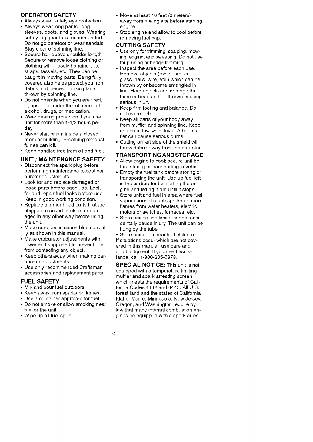
wARNING: Trimmer line throws ob-
jects violently. You and others can be
blinded/injured. Wear eye and leg
protection. Keep body parts clear of ro-
tating line. Keep children, bystanders,
and animals 50 feet (15 meters) away. If
approached stop unit immediately.
Eye Protection
/ HazardZone
E oots
DANGER: Never use blades or flailing
devices. This unit is designed for line
trimmer use only. Use of any other ac-
cessories or attachments will increase
the risk of injury.
If situations occur which are not
covered in this manual, use care and
good judgement. If you need
assistance, contact your Authorized
Service Dealer or call 1-800-235-5878.
2
Page 3
OPERATORSAFETY
•Alwayswearsafetyeyeprotection.
•Alwayswearlongpants,long
sleeves,boots,andgloves.Wearing
safetylegguardsisrecommended.
Donotgobarefootorwearsandals.
Stayclearofspinningline.
•Securehairaboveshoulderlength.
Secureorremovelooseclothingor
clothingwithlooselyhangingties,
straps,tassels,etc.Theycanbe
caughtinmovingparts.Beingfully
coveredalsohelpsprotectyoufrom
debrisandpiecesoftoxicplants
thrownbyspinningline.
•Donotoperatewhenyouaretired,
ill,upset,orundertheinfluenceof
alcohol,drugs,ormedication.
•Wearhearingprotectionifyouuse
unitformorethan1-1/2hoursper
day.
•Neverstartorruninsideaclosed
roomorbuilding.Breathingexhaust
fumescankill.
•Keephandlesfreefromoilandfuel.
UNIT / MAINTENANCE SAFETY
• Disconnect the spark plug before
performing maintenance except car-
buretor adjustments.
• Look for and replace damaged or
loose parts before each use. Look
for and repair fuel leaks before use.
Keep in good working condition.
• Replace trimmer head parts that are
chipped, cracked, broken, or dam-
aged in any other way before using
the unit.
• Make sure unit is assembled correct-
ly as shown in this manual.
• Make carburetor adjustments with
lower end supported to prevent line
from contacting any object.
• Keep others away when making car-
buretor adjustments.
• Use only recommended Craftsman
accessories and replacement parts.
FUEL SAFETY
• Mix and pour fuel outdoors.
• Keep away from sparks or flames.
• Use a container approved for fuel.
• Do not smoke or allow smoking near
fuel or the unit.
• Wipe up all fuel spills.
• Move at least 10 feet (3 meters)
away from fueling site before starting
engine.
• Stop engine and allow to cool before
removing fuel cap.
CUTTING SAFETY
• Use only for trimming, scalping, mow-
ing, edging, and sweeping. Do not use
for pruning or hedge trimming.
• Inspect the area before each use.
Remove objects (rocks, broken
glass, nails, wire, etc.) which can be
thrown by or become entangled in
line. Hard objects can damage the
trimmer head and be thrown causing
serious injury.
• Keep firm footing and balance. Do
not overreach.
• Keep all parts of your body away
from muffler and spinning line. Keep
engine below waist level. A hot muf-
fler can cause serious burns.
• Cutting on left side of the shield will
throw debris away from the operator.
TRANSPORTING AND STORAGE
• Allow engine to cool; secure unit be-
fore storing or transporting in vehicle.
• Empty the fuel tank before storing or
transporting the unit. Use up fuel left
in the carburetor by starting the en-
gine and letting it run until it stops.
• Store unit and fuel in area where fuel
vapors cannot reach sparks or open
flames from water heaters, electric
motors or switches, furnaces, etc.
• Store unit so line limiter cannot acci-
dentally cause injury. The unit can be
hung by the tube.
• Store unit out of reach of children.
If situations occur which are not cov-
ered in this manual, use care and
good judgment. If you need assis-
tance, call 1-800-235-5878.
SPECIAL NOTICE: This unit is not
equipped with a temperature limiting
muffler and spark arresting screen
which meets the requirements of Cali-
fornia Codes 4442 and 4443. All U.S.
forest land and the states of California,
Idaho, Maine, Minnesota, New Jersey,
Oregon, and Washington require by
law that many internal combustion en-
gines be equipped with a spark arres-
Page 4
torscreen.Ifyouoperateinalocale
wheresuchregulationsexist,youare
legallyresponsibleforinstallingand
maintainingtheoperatingconditionof
theseparts.Failuretodosoisaviola-
tionoflaw.ContactaSearsService
Centerforthecorrectparts.
SPECIALNOTICE:Exposureto
vibrationsthroughprolongeduseof
gasolinepoweredhandtoolscould
causebloodvesselornervedamage
inthefingers,hands,andjointsof
peoplepronetocirculationdisordersor
abnormalswellings.Prolongedusein
coldweatherhasbeenlinkedtoblood
vesseldamageinotherwisehealthy
people.Ifsymptomsoccursuchas
numbness,pain,lossofstrength,
changeinskincolorortexture,orloss
offeelinginthefingers,hands,or
joints,discontinuetheuseofthistool
andseekmedicalattention.Ananti-
vibrationsystemdoesnotguarantee
theavoidanceoftheseproblems.Us-
erswhooperatepowertoolsonacon-
tinualandregularbasismustmonitor
closelytheirphysicalconditionandthe
conditionofthistool.
CARTONCONTENTS
Checkcartoncontentsagainstthefol-
lowinglist.
Model 358.798210
• Trimmer
• Shield
• Wing Nut (screwed onto shield)
• Container of Oil
Examine parts for damage. Do not use
damaged parts.
NOTE: If you need assistance or find
parts missing or damaged, call
1-800-235-5878.
It is normal for the fuel filter to rattle in
the empty fuel tank.
Finding fuel or oil residue on muffler is
normal due to carburetor adjustments
and testing done by the manufacturer.
ASSEMBLY
WARNING:If received assembled,
repeat all steps to ensure your unit is
properly assembled and all fasteners
are secure.
ADJUSTING THE HANDLE
WARNING:When adjusting the han-
dle, be sure it remains between the
trigger and the safety label.
• Loosen wing nut or knob on handle.
• Rotate the handle on the tube to an
upright position; retighten wing nut.
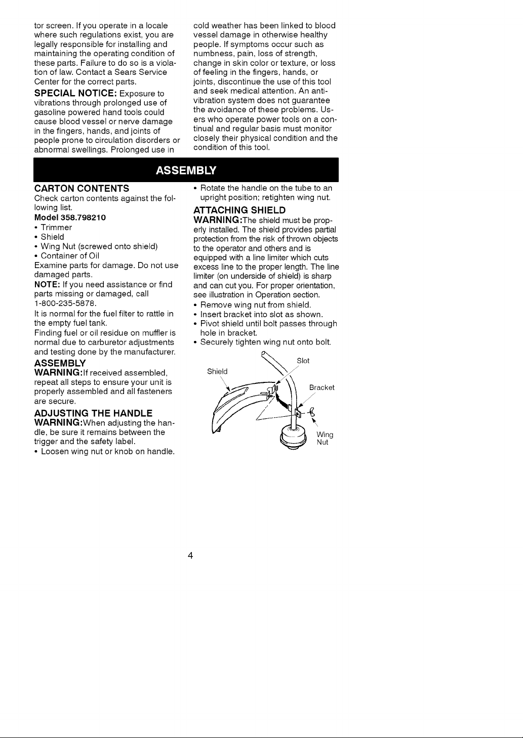
ATTACHING SHIELD
WARNING:The shield must be prop-
erly installed. The shield provides partial
protection from the risk of thrown objects
to the operator and others and is
equipped with a line limiter which cuts
excess line to the proper length. The line
limiter (on underside of shield) is sharp
and can cut you. For proper orientation,
see illustration in Operation section.
• Remove wing nut from shield.
• Insert bracket into slot as shown.
• Pivot shield until bolt passes through
hole in bracket.
• Securely tighten wing nut onto bolt.
Slot
Shield
,J
Bracket
Wing
Nut
Page 5

KNOW YOUR TRIMMER
READ THIS OPERATOR'S MANUAL AND SAFETY RULES BEFORE OPERATING YOUR
UNIT. Compare the illustrations with your unit to familiarize yourself with the loca-
tion of the various controls and adjustments. Save this manual for future refer-
ence.
Assist Handle
Tube
J
Trimmer
Head
Line
Limiter
Blade
Muffler
ON/STOP Trigger
Switch \
Starter
"\ Throttle
Spark Plug
Choke Lever
Primer Bulb
Fuel Mix
Fill Cap
Shield
ON/STOP SWITCH
The STOP switch is used to stop engine.
Press and hold switch to stop engine.
PRIMER BULB
The primer bulb removes air from the
fuel lines and fills them with fuel. This
allows you to start the engine with few-
er pulls on the starter rope. Activate
the primer bulb by pressing it and
BEFORE STARTING ENGINE
WARNING:Be sure to read the fuel
information in the safety rules before
you begin. If you do not understand
the safety rules, do not attempt to fuel
your unit. Call 1-800-235-5878.
FUELING ENGINE
This engine is certified to operate on
unleaded gasoline. Before operation,
gasoline must be mixed with a good
quality 2-cycle air-cooled engine oil.
We recommend Craftsman brand oil.
Mix gasoline and oil at a ratio of 40:1
(A 40:1 ratio is obtained by mixing 3.2
ounces of oil with 1 gallon of unleaded
gasoline). DO NOT USE automotive oil
or boat oil. These oils will cause
engine damage. When mixing fuel,
follow instructions printed on container.
allowing it to return to its original form.
CHOKE
The choke helps to supply fuel to the
carburetor during starting. This allows
you to start a cold engine. Activate the
choke by moving choke lever to the Full
position. After the engine has started,
move the choke to the Off position.
Once oil is added to gasoline, shake
container momentarily to assure that
the fuel is thoroughly mixed. Always
read and follow the safety rules
relating to fuel before fueling your unit.
IMPORTANT
Experience indicates that alcohol
blended fuels (called gasohol or using
ethanol or methanol) can attract mois-
ture which leads to separation and
formation of acids during storage.
Acidic gas can damage the fuel sys-
tem of an engine while in storage.
To avoid engine problems, empty the
fuel system before storage for 30 days
or longer. Drain the gas tank, start the
engine and let it run until the fuel lines
and carburetor are empty. Use fresh
fuel next season.
5
Page 6

Neveruseengineorcarburetorclean-
erproductsinthefueltankorperma-
nentdamagemayoccur.
SeetheSTORAGEsectionforaddi-
tionalinformation.
STOPPINGYOURENGINE
• PressandholdtheOn/Stopswitchin
theSTOPposition.
• Ifenginedoesnotstop,movechoke
levertofullposition.
Engine
Stop
Switch",
STARTING YOUR ENGINE
COLD ENGINE OR WARM ENGINE
AFTER RUNNING OUT OF FUEL
WARNING:The trimmer head will
turn while starting the engine.
Avoid any contact with the muffler. A
hot muffler can cause serious burns.
• Rest engine and shield on ground,
supporting trimmer head off ground.
• Move the choke lever to the Full
Choke position.
• Slowly press the primer bulb 6 times.
• Squeeze and hold the throttle trigger.
Keep throttle trigger fully squeezed
until the engine runs smoothly.
ChokeLever
:; ;,Ohoke
Lever
U_ r
• Pull starter rope sharply 5 times.
NOTE: If the engine sounds as if it is
trying to start before the 5th pull, go to
the next step.
• Move the choke lever to the Half
Choke position.
• Pull starter rope sharply until engine
runs, but no more than 6 pulls.
NOTE: If the engine has not started
after 6 pulls (at half choke), check to
make sure the choke lever is in the
proper position. Then, move the choke
lever to the Full Choke position and
press the primer bulb 6 times; squeeze
and hold the throttle trigger and pull
the starter rope 2 more times. Move
the choke lever to Half Choke and pull
the starter rope until the engine runs,
but no more than 6 more pulls. If the
engine still has not started, it is prob-
ably flooded. Proceed to "Starting a
Flooded Engine."
• Allow the engine to run 10 seconds,
then move the choke lever to Off
Choke. Allow the unit to run for 30
more seconds at Off Choke before
releasing the throttle trigger.
NOTE: If engine dies with the choke
lever at the Off Choke position, move
the choke lever to Half Choke and pull
the rope until engine runs.
STARTING A WARM ENGINE
• Move the choke lever to the Half
Choke position.
• Squeeze and hold the throttle trigger.
Keep throttle trigger fully squeezed
until the engine runs smoothly.
• Pull starter rope sharply until engine
runs, but no more than 5 pulls.
• Allow engine to run 15 seconds, then
move the choke lever to Off Choke.
NOTE: If engine has not started, pull
starter rope 5 more pulls. If engine still
does not run, it is probably flooded.
DIFFICULT STARTING OR
STARTING A FLOODED ENGINE
Flooded engines can be started by
placing the choke lever in the Off
Choke position; then, pull the rope to
clear the engine of excess fuel. This
could require pulling the starter handle
many times depending on how badly
the unit is flooded.
If the unit still doesn't start, refer to
TROUBLESHOOTING chart or call
1-800-235-5878.
Page 7

OPERATING INSTRUCTIONS
OPERATING POSITION
To advance line, tap bottom of trimmer
head on ground one time.
ALWAYS WEAR: _ _. _
j_ Eye Protection
H_°;gY _t_s __
Cut from your right to your left.
Bring the engine to cutting speed be-
fore entering the material to be cut.
Do not run the engine at a higher
speed than necessary. The cutting line
will cut efficiently when the engine is
run at less than full throttle. At lower
speeds, there is less engine noise and
vibration. The cutting line will last
longer and will be less likely to "weld"
onto the spool.
If the trimmer head does not turn when
the engine is in operation, make sure
the drive shaft housing is properly
seated in engine shroud.
Always release the throttle trigger and
allow the engine to return to idle speed
when not cutting.
To stop engine:
• Release the throttle trigger.
• Push and hold down the on/stop
switch until the engine has stopped
completely.
TRIMMER LINE ADVANCE
The trimmer line will advance approxi-
mately 2 in. (5 cm) each time the bot-
tom of the trimmer head is tapped on
the ground with the engine running at
full throttle.
The most efficient line length is the
maximum length allowed by the line
limiter.
Always keep the shield in place when
the tool is being operated.
To Advance Line:
• Operate the engine at full throttle.
• Hold the trimmer head parallel to and
above the grassy area.
• Tap the bottom of the trimmer head
lightly on the ground one time. Ap-
proximately 2 in. (5 cm) of line will be
advanced with each tap.
Llrnplei_e rg_hU.ts line t° "_
Always tap the trimmer head on a
grassy area. Tapping on surfaces such
as concrete or asphalt can cause ex-
cessive wear to the trimmer head.
Ifthe line is worn down to 2 in. (5 cm)
or less, more than one tap will be re-
quired to obtain the most efficient line
length.
WARNING;Use only .080" (2 mm)
diameter line. Other sizes of line will
not advance properly and can cause
serious injury. Do not use other materi-
als such as wire, string, rope, etc. Wire
can break off during cutting and be-
come a dangerous missile that can
cause serious injury.
CUTTING METHODS
WARNING:Use minimum speed and
do not crowd the line when cutting
around hard objects (rock, gravel,
fence posts, etc.), which can damage
the trimmer head, become entangled
in the line, or be thrown causing a seri-
ous hazard.
• The tip of the line does the cutting.
You will achieve the best perform-
ance and minimum line wear by not
crowding the line into the cutting
area. The right and wrong ways are
shown below.
Tip of the Line Line Crowded Into
Does The Cutting Work Area
Right_' Wrong " _'=.
• The line will easily remove grass and
weeds from around walls, fences,
trees and flower beds, but it also can
cut the tender bark of trees or shrubs
and scar fences. To help avoid dam-
age especially to delicate vegetation
or trees with tender bark, shorten line
to 4-5 in. (10-13 cm) and use at less
than full throttle.
Page 8

•Fortrimmingorscalpinguseless
thanfullthrottletoincreaselinelife
anddecreaseheadwearespecially:
•Duringlightdutycutting
•Nearobjectsaroundwhichtheline
canwrapsuchassmallposts
treesorfencewire
•Formowingorsweepingusefull
throttleforagoodcleanjob
WARNING:Alwaysweareyeprotec-
tion.Neverleanoverthetrimmerhead.
Rocksordebriscanricochetorbe
thrownintoeyesandfaceandcause
blindnessorotherseriousinjury.
TRIMMING- Holdthebottomofthe
trimmerheadabout3in.(8cm)above
thegroundandatanangle.Allowonly
thetipofthelinetomakecontact.Do
notforcetrimmerlineintoworkarea.
Trimming . • _.
3in.
Above Ground y _" __'__,
MOWING - Your trimmer is ideal for
mowing in places conventional lawn
mowers cannot reach. In the mowing
position, keep the line parallel to the
ground. Avoid pressing the head into
the ground as this can scalp the
ground and damage the tool.
Mowing I_
_ 44
.___. -- ;_
÷_,;_ :_' _
SWEEPING - The fanning action of
the rotating line can be used for a
quick and easy clean up Keep the line
parallel to and above the surfaces be
ing swept and move the tool from side
to side
Sweeping
SCALPING - The scalping technique
removes unwanted vegetation. Hold
the bottom of the trimmer head about 3
in. (8 cm) above the ground and at an
angle. Allow the tip of the line to strike
the ground around trees, posts, monu-
ments, etc. This technique increases
line wear.
Scalping ...........
EDGING - Your unit can be used for
edging sidewalks, patios, driveways, etc.
While edging, allow the tip of the line to
make contact. Do not force line. Take
extra caution while edging as objects
can be thrown by trimmer line.
/
Page 9

MAINTENANCESCHEDULE
CARE & MAINTENANCE TASK WHEN TO PERFORM
Check for Loose fasteners and parts Before each use
Check for damaged or worn parts Before each use
Clean unit and labels After each use
Clean air filter Every 5 hours of operation
Replace spark plug Yearly
GENERAL RECOMMENDATIONS
The warranty on this unit does not cov-
er items that have been subjected to
operator abuse or negligence. To re-
ceive full value from the warranty, the
operator must maintain unit as instruct-
ed in this manual. Various adjustments
will need to be made periodically to
properly maintain your unit.
CHECK FOR LOOSE
FASTENERS AND PARTS
• Spark Plug Boot
• Air Filter
• Housing Screws
• Assist Handle Screws
• Debris Shield
CHECK FOR DAMAGED OR
WORN PARTS
Refer replacement of damaged/worn
parts to your Sears Service Center.
• On/Stop Switch - Ensure On/Stop
switch functions properly by pressing
and holding the switch in the "Stop"
position. Make sure engine stops;
then restart engine and continue.
• Fuel Tank - Discontinue use of unit if
fuel tank shows signs of damage or
leaks.
• Debris Shield - Discontinue use of
unit if debris shield is damaged.
CLEAN UNIT & LABELS
• Clean the unit using a damp cloth
with a mild detergent.
• Wipe off unit with a clean dry cloth.
CLEAN AIR FILTER
Do not clean filter in gasoline or other
flammable solvent to avoid creating a
fire hazard or producing harmful evap-
orative emissions.
A dirty air filter decreases engine per-
formance and increases fuel consump-
tion and harmful emissions. Always
clean after every 5 hours of operation.
• Clean the cover and the area around
it to keep dirt from falling into the
carburetor chamber when the cover
is removed.
• Remove parts as illustrated.
• Wash the filter in soap and water.
• Allow filter to dry.
• Add a few drops of oil to the filter;
squeeze the filter to distribute oil.
• Replace parts.
_ Air Filter
_'_ ._-_ Screws
Air Filter -" "_
Cover
REPLACE SPARK PLUG
Replace the spark plug each year to
ensure the engine starts easier and
runs better. Set spark plug gap at
.025 in. Ignition timing is fixed and
nonadjustable.
• Twist, then pull off spark plug boot.
• Remove spark plug from cylinder
and discard.
• Replace with Champion CJ-8Y spark
plug and tighten with a 3/4 in. socket
wrench (10-12 ft.-Ibs).
• Reinstall the spark plug boot.
Page 10

REPLACING THE LINE
• Push and hold the engine stop switch
in the stop/off position until the unit has
fully stopped.
• Disconnect the spark plug lead wire.
• Remove the spool by firmly pulling on
the tap button.
• Clean entire surface of hub and spool.
• Replace with a pre-wound spool, or
cut two 12.5 foot (3.8 m) lengths of
.080" (2 mm) diameter Craftsman
brand line. Never use wire, rope,
string, etc., which can break off and
become a dangerous missile.
• Insert ends of line about 1/2 inch (1 cm)
into the small holes inside spool.
Spool /_ Small
............._-// Holes
• Wind the line evenly and tightly onto
the spool. Wind in the direction of the
arrows found on the spool.
• Push the line into the notches, leaving
3 to 5 inches (7 - 12 cm) unwound.
• Insert the line into the the exit holes in
the hub as shown in the illustration.
Line exit holes Line in Notch
\
\\\\ /
\'i
"I
J Line in Notch
Hub
• Align notches with the line exit hole.
• Push the spool into the hub until it
snaps into place.
• Pull the line extending outside of the
hub to release it from the notch.
CARBURETOR ADJUSTMENT
WARNING:The trimmer head will be
spinning during most of this procedure.
Wear your protective equipment and
observe all safety precautions. After
making mixture adjustments, recheck
idle speed.
Carburetor adjustment is critical and if
done improperly can permanently
damage the engine as well as the car-
buretor. If you require further assis-
tance or are unsure about performing
this procedure, call our customer as-
sistance help line at 1-800-235-5878.
Old fuel, a dirty air filter, a dirty fuel fil-
ter, or flooding may give the impres-
sion of an improperly adjusted carbu-
retor. Check these conditions before
adjusting the carburetor.
The carburetor has been carefully set
at the factory. Adjustments may be
necessary if you notice any of the fol-
lowing conditions:
• Engine will not idle. See "Idle Speed"
under adjusting procedure.
• Engine dies or hesitates instead of
accelerating. See "Acceleration
Check" under adjusting procedure.
• Loss of cutting power. See "Mixture
Adjustment" under adjusting
procedure.
There are two adjustment screws on
the carburetor.
Screw
Mixture Screw. Air Filter
(with Limiter
Cap) "_ Cover
CARBURETOR PRESETS
When making carburetor preset adjust-
ments, do not force plastic limiter caps
beyond stops or damage will occur.
If carburetor presets are not needed,
proceed to "Adjusting Procedure, Idle
Speed."
To adjust presets:
• Turn mixture screw counterclockwise
until it stops.
• Turn the idle speed screw clockwise
until it stops. Now turn counterclock-
wise 4-1/2 turns.
• Start motor, cut grass for 3 minutes,
and proceed to the adjustment
section. If engine does not start,
refer to troubleshooting chart or call
1-800-235-5878.
• If engine performance is acceptable
at the preset positions, no further
adjustment is necessary.
10
Page 11

ADJUSTING PROCEDURE
Idle Speed
Allow engine to idle. Adjust speed until
engine runs without stalling.
• Turn clockwise to increase engine
speed if engine stalls or dies.
• Turn counterclockwise to decrease
speed.
No further adjustments are necessary
if performance is satisfactory.
Mixture Adjustment "H"
DO NOT operate engine at full throttle
for prolonged periods while making ad-
justments. Damage to the engine can
occur. Extend line to the length allow
by the line limiter and cut some grass.
Based on performance while cutting,
turn the mixture adjustment in
1/16-turn increments as follows:
• Clockwise until the engine has good
power while cutting with no hesita-
tion.
Do not adjust by sound or speed, but
judge by how well the engine per-
forms while cutting.
• Counterclockwise if the engine has
speed but dies or lacks power while
cutting.
After completing adjustments, check
for acceleration. Reset if necessary.
Acceleration Check
If engine dies or hesitates instead of
accelerating, turn mixture adjustment
counterclockwise until you have
smooth acceleration. Recheck and ad-
just as necessary for acceptable per-
formance.
Prepare unit for storage at end of sea-
son or if it will not be used for 30 days
or more.
WARNING:
• Allow engine to cool, and secure the
unit before storing or transporting.
• Store unit and fuel in a well venti-
lated area where fuel vapors cannot
reach sparks or open flames from
water heaters, electric motors or
switches, furnaces, etc.
• Store unit with all guards in place.
Position unit so that any sharp object
cannot accidentally cause injury.
• Store unit and fuel well out of the
reach of children.
EXTERNAL SURFACES
If your unit is to be stored for a period
of time, clean it thoroughly before stor-
age. Store in a clean dry area.
• Lightly oil external metal surfaces.
FUEL SYSTEM
Under Fueling Engine in the Operating
Section of this manual, see message
labeled IMPORTANT regarding the use
of gasohol in your engine.
Fuel stabilizer is an acceptable alter-
native in minimizing the formation of
fuel gum deposits during storage. Add
stabilizer to the gasoline in the fuel
tank or fuel storage container. Follow
the mix instructions found on stabilizer
container. Run engine at least 5 min-
utes after adding stabilizer.
CRAFTSMAN 40:1,2-cycle engine oil
(air cooled) is already blended with
fuel stabilizer. If you do not use this
Sears oil, you can add a fuel stabilizer
to your fuel tank.
INTERNAL ENGINE
• Remove spark plug and pour 1 tea-
spoon of 40:1,2-cycle engine oil (air
cooled) through the spark plug open-
ing. Slowly pull the starter rope 8 to
10 times to distribute oil.
• Replace spark plug with new one of
recommended type and heat range.
• Clean air filter.
• Check entire unit for loose screws,
nuts, and bolts. Replace any dam-
aged, broken, or worn parts.
• At the beginning of the next season,
use only fresh fuel having the proper
gasoline to oil ratio.
OTHER
• Do not store gasoline from one sea-
son to another.
• Replace your gasoline can if it starts
to rust.
11
Page 12

TROUBLESHOOTINGCHART
TROUBLE
Engine will not
start.
CAUSE
• Engine flooded.
• Fuel tank empty.
• Spark plug not firing.
• Fuel not reaching
carburetor.
• Compression low.
REMEDY
• See "Starting Instructions."
• Fill tank with correct fuel mixture.
• Install new spark plug.
• Check for dirty fuel filter; replace.
Check for kinked or split fuel line;
repair or replace.
• Contact a Sears Service Center.
Engine will not
idle properly.
Engine will not
accelerate,
lacks power,
or dies under
a load.
Engine smokes
excessively.
Engine runs hot.
YOUR WARRANTY RIGHTS AND
OBLIGATIONS: The U. S. Environ-
mental Protection Agency/California
Air Resources Board and SEARS,
ROEBUCK AND CO., USA are
pleased to explain the emissions con-
trol system warranty on your lawn and
garden equipment engine. All new util-
ity and lawn and garden equipment
engines must be designed, built, and
equipped to meet the stringent anti-
smog standards. SEARS must warrant
the emission control system on your
lawn and garden equipment engine for
• Idle speed set too low.
• Idle speed set too high.
• Carburetor requires
adjustment.
• Crankshaft seals worn.
• Compression low.
• Air filter dirty.
• Spark plug fouled.
• Carburetor requires
adjustment.
• Carbon build up.
• Compression low.
• Choke partially on.
• Fuel mixture incorrect.
• Air filter dirty.
• Carburetor requires
adjustment.
• Fuel mixture incorrect.
• Spark plug incorrect.
• Carburetor requires
adjustment
• Carbon build up.
• Adjust idle speed screw
clockwise to increase speed.
• Adjust idle speed screw counter-
clockwise to reduce speed.
• See "Carburetor Adjustments."
• Contact a Sears Service Center.
• Contact a Sears Service Center.
• Clean or replace air filter.
• Clean or replace spark plug
and re-gap.
• See "Carburetor Adjustments."
• Contact a Sears Service Center.
• Contact a Sears Service Center.
• Move choke to off position.
• Empty fuel tank and refill with
correct fuel mixture.
• Clean or replace air filter.
• See "Carburetor Adjustments."
• See "Fueling Your Unit."
• Replace with correct spark plug.
• See "Carburetor Adjustments."
• Contact a Sears Service Center.
the periods of time listed below pro-
vided there has been no abuse, ne-
glect, or improper maintenance of your
lawn and garden equipment engine.
Your emission control system includes
parts such as the carburetor and the
ignition system. Where a warrantable
condition exits, SEARS will repair your
lawn and garden equipment engine at
no cost to you. Expenses covered un-
der warranty include diagnosis, parts
and labor. MANUFACTURER'S WAR-
RANTY COVERAGE: If any emissions
related part on your engine (as listed
12
Page 13

underEmissionsControlWarranty
PartsList)isdefectiveoradefectin
thematerialsorworkmanshipofthe
enginecausesthefailureofsuchan
emissionrelatedpart,thepartwillbe
repairedorreplacedbySEARS.
OWNER'SWARRANTYRESPONSI-
BILITIES:Asthelawnandgarden
equipmentengineowner,youarere-
sponsiblefortheperformanceofthe
requiredmaintenancelistedinyour
Owner'sManual.SEARSrecommends
thatyouretainallreceiptscovering
maintenanceonyourlawnandgarden
equipmentengine,butSEARScannot
denywarrantysolelyforthelackofre-
ceiptsorforyourfailuretoensurethe
performanceofallscheduledmainte-
nance.Asthelawnandgarden
equipmentengineowner,youshould
beawarethatSEARSmaydenyyou
warrantycoverageifyourlawnand
gardenequipmentengineorapartofit
hasfailedduetoabuse,neglect,im-
propermaintenance,unapproved
modifications,ortheuseofpartsnot
madeorapprovedbytheoriginal
equipmentmanufacturer.Youarere-
sponsibleforpresentingyourlawnand
gardenequipmentenginetoaSEARS
authorizedrepaircenterassoonasa
problemexists.Warrantyrepairs
shouldbecompletedinareasonable
amountoftime,nottoexceed30days.
Ifyouhaveanyquestionsregarding
yourwarrantyrightsandresponsibili-
ties,youshouldcontactyournearest
authorizedservicecenterorcall
SEARSat1-800-473-7247WARRAN-
TY COMMENCEMENT DATE: The
warranty period begins on the date the
lawn and garden equipment engine is
purchased. LENGTH OF COVER-
AGE: This warranty shall be for a peri-
od of two years from the initial date of
purchase. WHAT IS COVERED: RE-
PAIR OR REPLACEMENT OF
PARTS. Repair or replacement of any
warranted part will be performed at no
charge to the owner at an approved
SEARS servicing center. If you have
any questions regarding your warranty
rights and responsibilities, you should
contact your nearest authorized ser-
vice center or call SEARS at
1-800-473-7247. WARRANTY PE-
RIOD: Any warranted part which is not
scheduled for replacement as required
maintenance, or which is scheduled
only for regular inspection to the effect
of "repair or replace as necessary"
shall be warranted for 2 years. Any
warranted part which is scheduled for
replacement as required maintenance
shall be warranted for the period of
time up to the first scheduled replace-
ment point for that part. DIAGNOSIS:
The owner shall not be charged for
diagnostic labor which leads to the de-
termination that a warranted part is de-
fective if the diagnostic work is per-
formed at an approved SEARS
servicing center. CONSEQUENTIAL
DAMAGES: SEARS may be liable for
damages to other engine components
caused by the failure of a warranted
part still under warranty. WHAT IS
NOT COVERED: All failures caused
by abuse, neglect, or improper mainte-
nance are not covered. ADD-ON OR
MODIFIED PARTS: The use of add-on
or modified parts can be grounds for dis-
allowing a warranty claim. SEARS is not
liable to cover failures of warranted
parts caused by the use of add-on or
modified parts. HOW TO FILE A
CLAIM: If you have any questions re-
garding your warranty rights and re-
sponsibilities, you should contact your
nearest authorized service center or
call SEARS at 1-800-473-7247.
WHERE TO GET WARRANTY SER-
VICE: Warranty services or repairs shall
be provided at all SEARS service cen-
ters. call: 1-800-473-7247. MAINTE-
NANCE, REPLACEMENT AND RE-
PAIR OF EMISSION RELATED
PARTS: Any SEARS approved re-
placement part used in the perfor-
mance of any warranty maintenance
or repair on emission related parts will
be provided without charge to the own-
er if the part is under warranty. EMIS-
SION CONTROL WARRANTY
PARTS LIST: Carburetor, Ignition Sys-
tem: Spark Plug (covered up to main-
tenance schedule), Ignition Module.
MAINTENANCE STATEMENT: The
owner is responsible for the perfor-
mance of all required maintenance as
defined in the owner's manual.
13
 Loading...