

Page 1
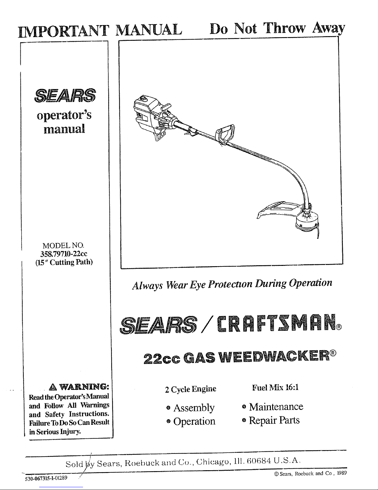
IMPORTANT MANUAL
Do Not Throw AwaY
g' _/ARS
operator's
manual
MODEL NO.
358.79710-22cc
(15" Cutting Path)
. A WAR_ING:
Read theOperators _hnual
and Follow All V_hrnings
and Safety Instructions.
FailureToDoSoCan Result
inSerious Injury.
Always Wear Eye Protection During Operation
C
22cc
2 Cycle Engine
• Assembly
®Operation
Fuel Mix 16:1
o Maintenance
e Repair Parts
Sold _y Sears, koebuck and Co. Chicago, ill., 60684 U_S..A,
"4 ff_ I
530-067315-1-0!289 / © Sears, Roebuck and Co, I989
Page 2
ONE YE.__RLIMITED WA_qRANTY ON CRAFTSMAN WEEDWACKER ®
ForOneYearfromdateofpurchase, whenthisWeedwacker ® ismalntained,lubricated,andtunedupaccordingtotheoperating
and maintenance instructions in the operator's manuat. Sears will repair fl'ee of charge any defect in material or workmanship "'_<:_
This warranty excludes nylon line. spark plug. and air cleaner; which are expendable parts and become worn during normal
use
If'this Weedwacker _ isused forcommercial or rentalpurposes, this warranty applies foronly 30 daysfrom the date of purchase,
WARRANTY SERVICE IS AVAILABLE BYCONTAC_ING IHE NEAREST SEARS SERV1CECENTERJDEPARTMEN 1
IN THE UNITED STATES This warranty applies onty while this product is in use in the United States ,--,_=,
This warranty gives you specific legal rights, and you may also have other rights which vary from state to state
SEARS ROEBUCK AND CO DEP"f 698173[ASEARSTOWERCHtCAGO. Ik 60684
TABLE @F
WARNINGS AND SAFETY INSTRUCTIONS
KNOW' YOUR TRIMMER
ASSEMBLY .
ACCESSORIES
ENGINE INFORMATION
A Fueling Your Engine
B Pre-Operation Checks
C Starting Instructions
D, Operating Instructions
USING YOUR TRIMMER
A Trimmer Safety
B Trimmer Line Advance
C Cutting Methods
D Line Replacement
3
6
7
I0
I1
11
12
12
13
13
14
14
I5
16
GENERAL MAINTENANCE 17
17
A Maintenance Safety
B Air Filter 17
C Starter Rope 18
D Flexible Drive Shaft Lubrication 19
E Carburetor Adjustments 20
F Storage 22
GA'frouble Shooting Chart 22
REPAIR PARTS LIS'I- 23
INDEX 26
QUICK REFERENCE PAGE 27
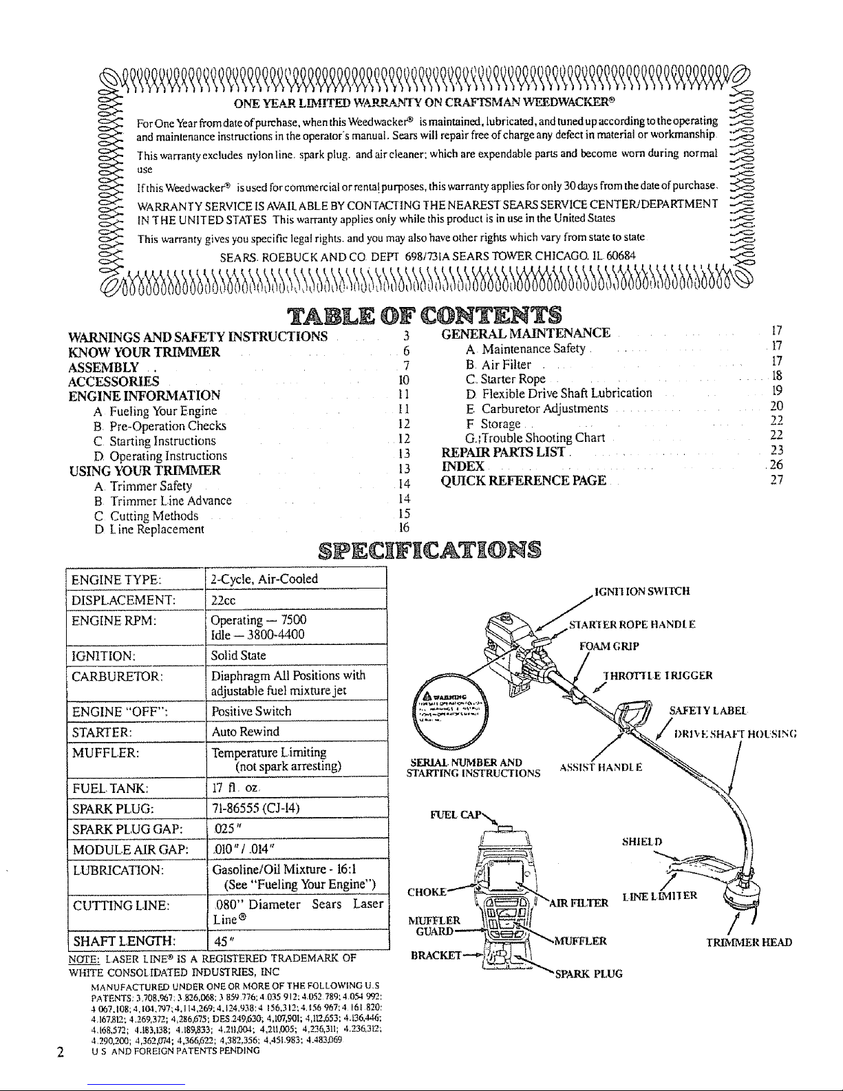
ENGINE TYPE:
DISPLACEMENT:
ENGINE RPM:
IGNITION:
CARBURETOR:
ZNGIN -0@:::
STARTER.:
MUFFLER:
FUEL, TANK:
SPARK PLUG:
SPARK PLUG GAP:
MODULE AIR GAP:
LUBRICATION:
CUTTING LINE:
$tPN ;gNgCAT [@NN
2-Cycle, Air-Cooled
22cc
Operating- 7500
Idle -- 13800-4400
Solid State
Diaphragm All Positions with
i adjustable fuel mixture jet
Positive Switch
Auto Rewind
Temperature Limiting
(not spark arresting)
t7 fl, oz,
7t-86555 (CJ-I4)
025"
_010" / ,014"
Gasoline/Oil Mixture- 16:i
(,See "Fueling You[Engine")__
080" Diameter Sears Laser
Line ®
SHAFT LENGTH: 45"
NOTE: LASER LINt_ IS A REGISTERED TRADEMARKOF
WHITE CONSOLIDAfED INDUS'IRJES, INC
MANUFACTURED UNDER ONE OR MORE OF THE FOLLOWING U.S
PATENTS: 3,708,967:3 826,068; 3 859 776:4035 912: 4,052789; 4054 992:
.I 007.108;4,104.797:4,11.t,269:4,124,938:4 156.312;4,156967;4 16t 820:
4,167,812; 4,269,372; 4,286,6"/5; DES 249,630; 4A07,901; 4,112,653: 4A36,446;
4,168,572.; 4.t83,138; 4,!89,833; 4.21|,004; 4,211,005; 4,236,311; 4,236,3L2;
4290,200; 4,362,074; 4,366.622; 4,382,356; 4,45t.983; 4.483,069
O S AND FOREIGN PATENTS PENDING
STARTING INSTRUCTIONS '*........... * ...... _/
"%,
SHIEtD 11
TRIMMER HEAD
B
'SPARK PLUG
Page 3
WA INGS AND SAFETY
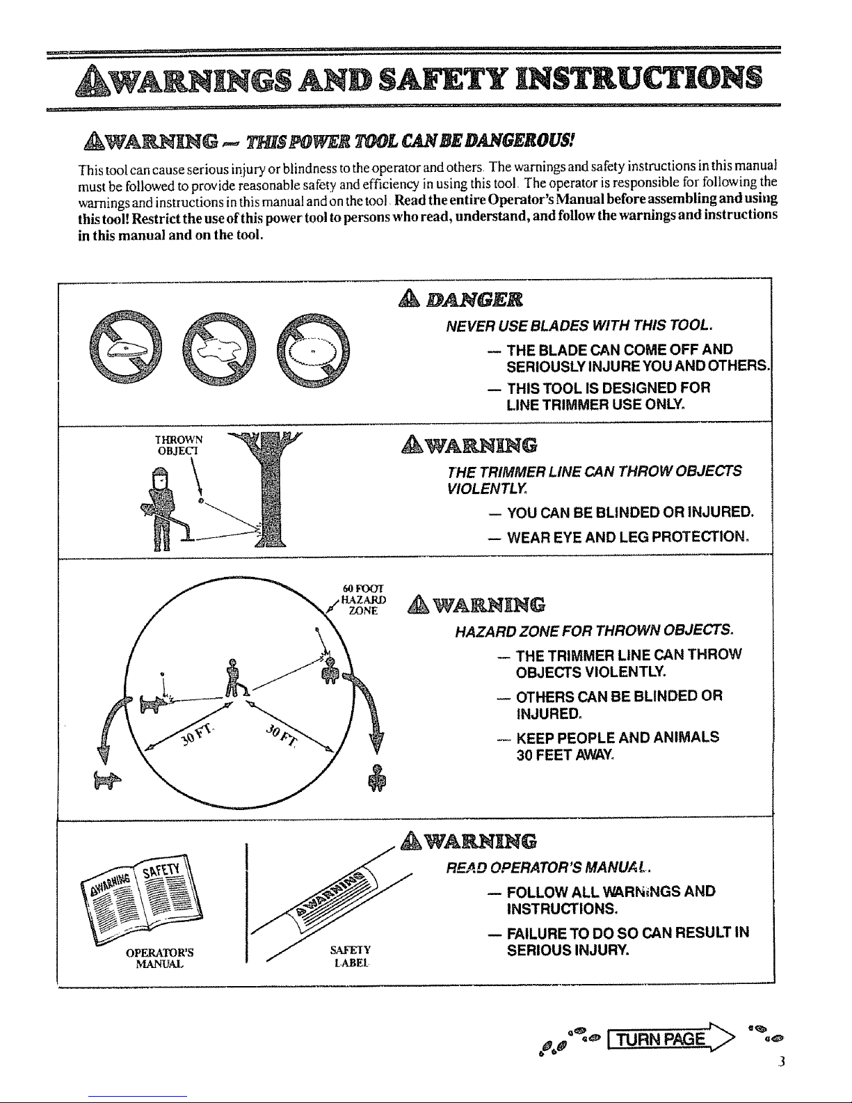
This tool can cause serious injury or blindness to the operator and others, The warnings and safety instructions in this manual
must be followed to provide reasonable safety and efficiency in using this tool, The operator is responsible for following the
warnings and instructions in this manual and on the tool. Read the entire Operator's Manual before assembling and using
this tool! Restrict the use of this power tool to persons who read, understand, and follow the warnings and instructions
in this manual and on the tool.
A DANGER
NEVER USE BLADES WITH THIS TOOL.
-- THE BLADE CAN COME OFF AND
SERIOUSLY INJURE YOU AND OTHERS.
-- THIS TOOL IS DESIGNED FOR
LINE TRIMMER USE ONLY,
THROWN
OBJECI
THE TRIMMER LINE CAN THROW OBJECTS
VIOLENTLY.
-- YOU CAN BE BLINDED OR INJURED.
-- WEAR EYE AND LEG PROTECTION,
HAZARD ZONE FOR THROWN OBJECTS.
-- THE TRIMMER LINE CAN THROW
OBJECTS VIOLENTLY.
-- OTHERS CAN BE BLINDED OR
INJURED_
KEEP PEOPLE AND ANIMALS
30 FEET AWAY_
OPERATOR'S
MANUAL
READ OPERATOR S MANUAl,.
-- FOLLOW ALL WARNINGS AND
INSTRUCTIONS.
- FAILURETODOSOCANRESULTIn
/ LA_E_ SERIOUS INJURY.
oaoa°*,*"I TURN PAGE,:"> "%_
3
Page 4

(this page intentionally left blank)
Page 5

,1: ,.
tL ii
i i ii1,1,,11111......................... , .......
,,, ,,_,.., • ,,
1 Always wear a safety face shield or goggles See
"Accessories ""
2 Always wear heavy, long pants, boots and gloves Do
not wear loose clothing, jewelry, short pants, sandals
or go barefoot Secure hair so it is above shoulder
length Being fully coveled will help protect you from pieces
of toxic plants such as poison ivy thrown by the Trimmer
Head which could be more of a hazard than touching the
plant itself
3 Do not operate this tool when you are tired, illor under
the influence of alcohol, drugs or medication
4 Always use the assist handle See "'Assembly"
5 Wear hearing protection if'you use this tcx:,lfar more
than II/2hours per day
6 Never san' or run theengine inside aclosed room or
building Breathing exhaust fumes can kill
7 Keep handles f'ree of oil and fuel
TOOLSAFETY
1 Inspect the entire tool bclorc each u._' Rcn!.=,,:
damaged parts Check tbr rue[ leaks and n_a!.,,_,,urcall
fiasteners are in place and _ccurel) taxtcncu
2 Replace trimmer head parts that arc cracked _:hippcd
or damaged in any wa,, beli_rc using the ux_l
3 Use only 080" diameter' Sears Laser Line ® Never
use wire, rope, string, etc.
4 Be sure the shield is properly attached.
5 Use only thespecified Irimmerhead See' Specifica-
tions ' Make sure the tfimnrer head L',properh installed
and fastened See "Assembly
6 Make carburetor adjustments with the drive shaft
housing supported to prevent the trimmer line from
contacting any object Hold the tool by hand Donor
use the optional shoulder strap for support
7 Keep others away when matdng carburetor adjustments°
8 Use only accessories or attachments recommended
fbr this tool by Sears
& FOg/., SA!_gT1"
1 Mix and pour fuel outdoors and where there arc no
sparks or flames
2 Use acontainer approved for fuel
3 Do not smoke or allow smoking near fuel or the tool or
while using the toot
4 Wipe up all fuel spills before starting engine
5 Move at least 10feet away fi'om fueling site before start-
ing engine
6 Stop engine before removing fuel cap
7 Empty the fuel tank before storing the tool
8 Store tool and fuel in an area where fuel vapors cannot
reach sparks or open flames from water heaters, elec-
tric motors or switches, furnaces, etc
.............. =, ,L,,,,.,,,1,,,
&
1 Inspect the area to be cu! before each use Remove
objects frocks, broken glass, nails, wire, string, etc )
which can be thrown or become entangled in the Irim-
mer head
2 Keep others including children, animals, bystanders
and helpers outside the 60 foot Hazard Zone Stop the
engine immediately if you are approached
3 Always keep the engine on the fight side of your body
4 Hold the tool firmly with both hands
5, Keep firm footing and balance Do not over-reach
6 Keep the trimmer head below waist level
7 Donotraisetheengineaboveyourwaist "[hetrimmer
head can come dangerously close to your body
g Keep all parts d'your body awa3i,from the trimmer head
and muffler when the engine is running
9 Use only forjobs explained in this manual
J_/dNTEN_NCE SA_T
I Maintain the tool according to recommended pro-
cedures. Keep the trimmer line at the proper length,
2 Disconnect the spark plug before performing mainte-
nance except for carburetor' adjustments
3 Make carburetor adjustments with thedrive shafxhous-
ing supported to prevent the trimmer line fiom contac-
ting any object Hold thetool byhand Do not use the
optional shoulder strap for support
Keep others awaywhenmaking carburetor adjustments
5,
Use only genuine replacement parts asrecommended
by Sears
l Hand carry the tool with the engine stopped, and the
muffler away from your body
2 A_low the engine to cool, empty the fuel tank, and
secure the tool before transporting in a vehicle or
storing,
3 Empty the fuel tank betbre storing the tool Use up fuel tef_in
the carburetor bystarting the engine and letting the engine mn
until it stops
4 Store tool and fuel in an area where fuel vapors cannot
reach sparks or open flames from water heaters, elec-
tric motors or switches, furnaces, etc
5 Store the too! so the tine limiter cannot accidentally
cause injury The tool can be hung by the drive shaft
housing
6. Store tool out of reach of children
If situations occur which are not covered in this manual,
use care and goodjudgmento Contact.your Sears Service
Center if you need assistance,
5
Page 6
.................................................... i ,HIq,UM U,I ,ll,,,,,I,,lll*U I, H NI
KNOW Y@UI IUbtK ER
&, IlCI_@Duc'rloN
C. CAR_N C@N_NTS
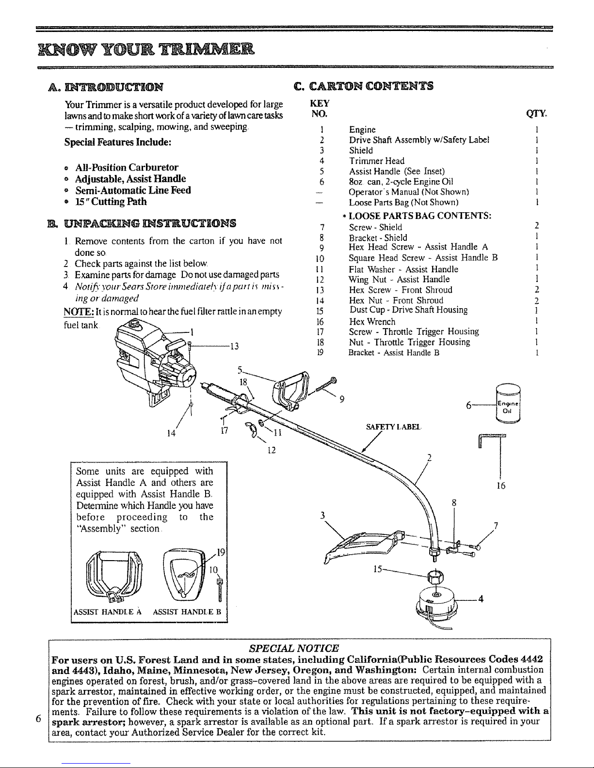
"four Trimmer isa versatile product developed for large KEY
lawns and to make short work of a variety of lawn care tasks NO,
-- trimming, scalping, mowing, and sweeping,
Special Features Include:
o All-Position Carburetor
o Adjustable, Assist Handle
o Semi-Automatic Line Feed
o 15" Cutting Path
• k UNPA_G _$_U_I@N$
1 Remove contents from the carton if you have not
done so
2 Check parts against the list below
3 Examine parts for damage Do not use damaged parts
4 NotifyyourSearsStoreimmediatel)iJapart i_ mis_-
ing or' damaged
NOTE: It is normal to hear the fuel filter rattle in an empty
fuel tank
13
1 Engine
2 Drive Shaft Assembly w/Safety Label
3 Shield
4 Trimmer Head
5 Assist Handle (See Inset)
6 8oz can, 2-cycle Engine Oil
-- Operators Manual (Not Shown)
-- L,ooseParts Bag (Not Shown)
*LOOSE PARTS BAG CONTENTS:
7 Screw - Shield
8 Bracket - Shield
9 Hex Head Screw - Assist Handle A
t0 Square Head Screw - Assist Handle B
11 Flat Washer - Assist Handle
12 Wing Nut - Assist Handle
13 Hex Screw _ Front Shroud
14 Hex Nut - Front Shroud
I5 Dust Cup -Drive Shaft Housing
16 Hex Wrench
17 Screw - Throttle Trigger Housing
18 Nut - Throttle Trigger Housing
19 Bracket - Assist Handle B
QT_
2
1
1
t
1
1
2
2
!
I
1
I
1
18
Some units are equipped with
Assist Handle A and others are
equipped with Assist Handle B,
Determine which Handle you have
before proceeding to the
"Assembly" section
ASSIST HANDLE B
G
ASSIST HANDt E
12
3
\
SPECIAL NOTICE
For users on U.S. Forest Land and in some states, including California(Public Resources Codes 4442
and 4443), Idaho, Maine, Minnesota, New Jersey, Oregon, and Washington: Certain internal combustion
engines operated on forest, brush, and/or grass-covered land in the above areas are required to be equipped with a
spark arrestor, maintained in effective working order, or the engine must be constructed, equipped, and maintained
for the prevention of fire. Check with your state or local authorities for regulations pertaining to these require-
ments. Failure to follow these requirements is a violation of the law. This unit is not factory-equipped with a
spark arrestor; however, a spark arrestor is available as an optional part. If a spark arrestor is required in your
area, contact your Authorized Service Dealer for the correct kit.
Page 7
_,,m ................. ,i,, ,,,,, ,,
__L_ tr (If to!!! is received assembled, repeat all steps in this section to be sure assembly is correct
and is adjusted for the operator.)
Ao PRF._A_A_ON
This Operator's Manual has been developed to help you
assemble the tool and to provide its safe operation It is
important that you read the entire manual to become
familiar with the tool before you begin assembly
2,. _ yOU will ne_tlh
a, Flathead Screwdriver.
b. i-1/4 inch wrench or adjustable wrench
co Hex Wrench provided with tool
X. READ YOUR OPE_kTOR°S I_&NUAL
A,_EMBLY STEPS
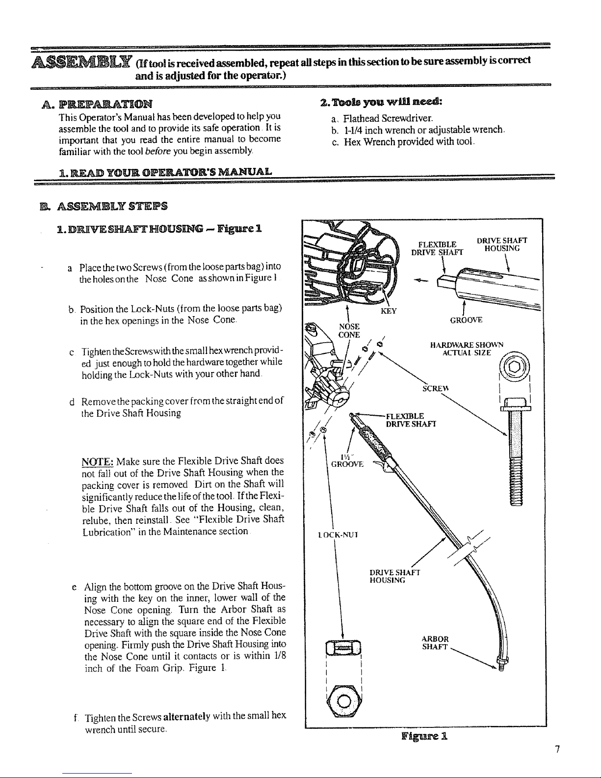
I. D_rE S_ HOUSING -- Figure 1
a Ptace the two Screws (from the loose parts bag) into
the holes on the Nose Cone as shown in Figure t
b Position the Lock-Nuts (from the loose parts bag)
in the hex openings in the Nose Cone.
Tighten theScrewswith the small hexwrench provid-
ed just enough to hold the hardware together while
holding the Lock-Nuts with your other hand.
Remove the packing cover from the straight end of'
the Drive Shaft Housing
NOTE: Make sure the Flexible Drive Shaft does
not fall out of the Drive Shaft Housing when the
packing cover is removed Dirt on the Shaft will
significantly reduce the life of the toot If the Ffexi-
ble Drive Shaft falls out of the Housing, clean,
relube, then reinstall See "Flexible Drive Shaft
Lubrication" in the Maintenance section
e
Align the bottom groove on the Drive Shaft Hous-
ing with the key on the inner, lower wail of the
Nose Cone opening. Turn the Arbor Shaft as
necessary to align the square end of the Flexible
Drive Shaft with the square inside the Nose Cone
opening_ Firmly push the Drive Shaft Housing into
the Nose Cone until it contacts or is within 1/8
inch of the Foam Grip. Figure t.
f Tighten the Screws alternately with the small hex
wrench until secure.
NOSE
CONE
1½'
3 ROOVE
KEY
FLLVO_BLE DRIVE SHAFT
DRIVE SHAFT HOUSING
GROOVE
/
I.OCK.NUI"
DRIVE SIIAFI
HOUSING
ARBOR
SttAFr
a
Page 8
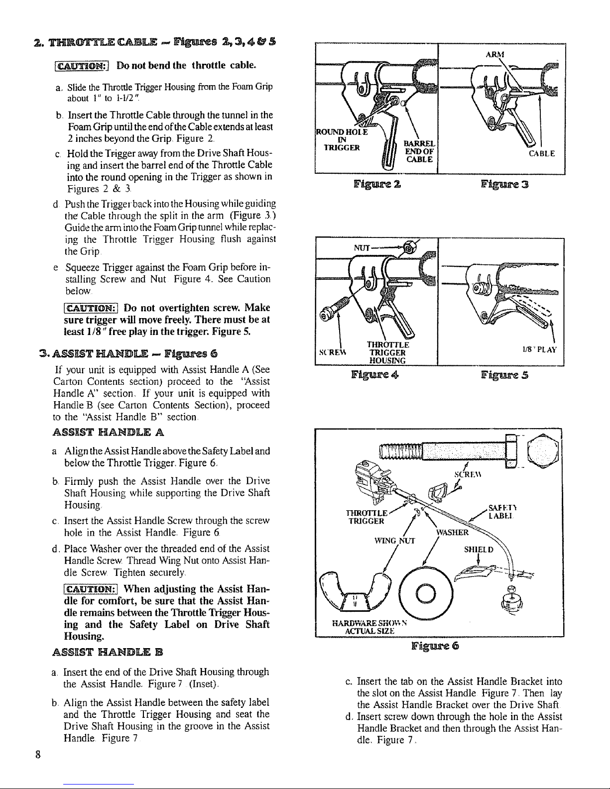
[_u'rloN:] Do not bend the throttle cable°
a, Slide the Throttle TriggerHousing from the Foam Grip
about 1" to 1-t/2"
bo Insert the Throttle Cable through the tunnel in the
Foam Grip until the end of the Cable extends at least
2 inches beyond the Grip, Figure 2
c Hold the Tl,igger away from the Drive Shaft Hous-
ing and insert the barrel end of the Throttle Cable
into the round opening in the Trigger as shown in
Figures 2 & 3
d Push the Trigge_ back into the Housing while guiding
the Cable through the split in the arm (Figure 3)
Guide the arm into the Foam Grip tunnel while replac-
ing the Throttle Trigger Housing flush against
the Grip
e Squeeze Trigger against the Foam Grip before in-
stalling Screw and Nut Figure 4_ See Caution
below
[CAU'rlON:I Do not overtighten screw. Make
sure trigger vdll move freely, There must be at
least 1/8" free play in the trigger. Figure 5.
3. A_I_T HANDI_ -- F_s 6
If your unit is equipped with Assist Handle A (See
Carton Contents section) proceed to the 'Assist
Handle A" section, If your unit is equipped with
Handle B (see Carton Contents Section), proceed
to the "Assist Handle B" section
ASSIST HANDLE A
a Align the Assist Handle above the Safety Label and
below the Throttle Trigger, Figure 6,
b Firmly push the Assist Handle over the Drive
Shaft Housing while supporting the Drive Shaft
Housing
c Insert the Assist Handle Screw through the screw
hole in the Assist Handle Figure 6
d Place Washer over the threaded end of the Assist
Handle Screw Thread Wing Nut onto Assist Han-
dle Screw Tighten securely,
[CAu'IrloN:] When adjusting the Assist Han-
dle for comfort, be sure that the Assist Han*
die remains between the Throttle 'lYigger Hous-
ing and the Safety Label on Drive Shaft
Housing.
ASSKST _--_NDLE B
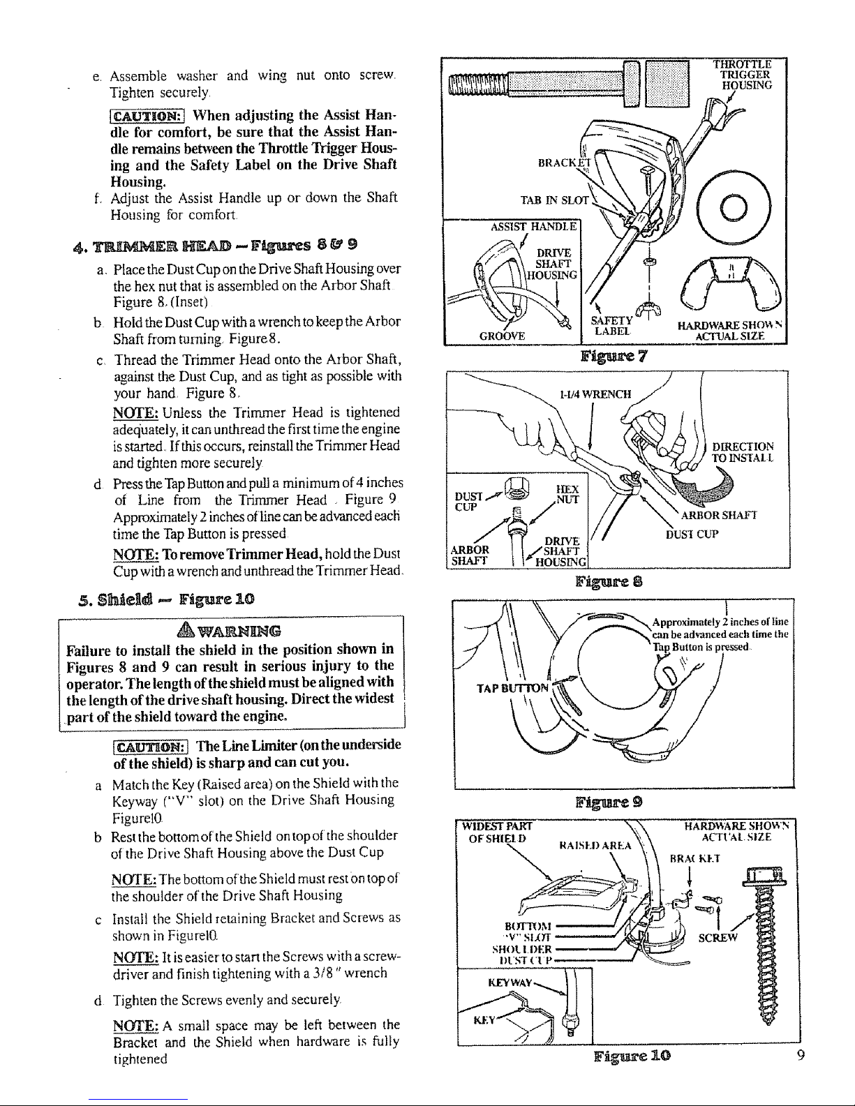
a Insert the end of the Drive Shaft Housing through
the Assist Handle Figure 7 (Inset)
b. Align the Assist Handle between the safety label
and the Throttle Trigger Housing and seat the
Drive Shaft Housing in the groove in the Assist
Handle Figure 7
ROUND HOLE
IN
TRIGGER
BARREL
ENDOF
CABLE
ARM
:c
CABLE
THROTTLE
TRIGGER U8 "PLAY
HOUSING
F gure 5
TRIGGER
SHIEL D
ACq_AL SiZE
6
c. Insert the tab on the Assist Handle Bracket into
the slot on the Assist Handle Figure 7, Then lay
the Assist Handle Bracket over the Drive Shaft
d. Insert screw down through the hole in the Assist
Handle Biacket and then through the Assist Han-
dle, Figure 7_
Page 9
e Assemble washer and wing nut onto screw,
Tighten securely,
lCAUTION:I When adjusting the Assist Han-
dle for comfort, be sure that the Assist Han-
dle remains between the Throttle Trigger Hous-
ing and the Safety Label on the Drive Shaft
Housing.
f_ Adjust the Assist Handle up or down the Shaft
Housing for' comtbrt
a, Place the Dust Cup on the Drive Shaft Housing over
the hex nut that is assembled on the Arbor Shaft
Figure 8, (Inset)
b Hold the Dust Cup with a wrench to keep the Arbor
Shaft from mining Figure 8.
c Thread the Trimmer Head onto the Arbor Shaft,
against the Dust Cup, and as tight as possible with
your hand, Figure 8,
NOTE: Urdess the Trimmer Head is tightened
adec_uately, it can unthread the first time the engine
is s_, If this occurs, reinstal! the Trimmer Head
and tighten more securely
d Press the Tap Button and pull a minimum of 4 inches
of Line from the Trimmer Head , Figure 9
Approximately 2 inches of line can be advanced each
time the Tap Button is pressed
NOTE: To remove Trimmer Head, hold the Dust
Cup with a wrench and unthread the Trimmer Head_
5. SlMeltd _ Figure 10
_WANNgN_
Failure to install the shield in the position shown in
Figures 8 and 9 can result in serious injury to the
operator. The length of the shield must be aligned with
the length of the drive shaft housing. Direct the widest
part of the shield toward the engine.
[CAU'riON: ] The Line Limiter (on the underside
of the shield) is sharp and can cut you.
Match the Key (Raised area) on the Shield with the
Keyway ("V" slot) on the Drive Shaft Housing
FigurelO
Rest the bottom of the Shield on topof the shoulder
of the Drive Shaft Housing above the Dust Cup
NOTE: The bottom of the Shield must rest Ontop of
the shoulder of the Drive Shaft Housing
Install the Shield retaining Bracket and Screws as
shown in FigurelO
N(YrE; It iseasier' to start the Screws with a screw-
driver and finish tightening with a 3/8" wrench
d Tighten the Screws evenly and securely
NOTE: A small space may be left between the
Bracket and the Shield when hardware is fully
tightened
THRffFTLE
TRIGGER
HOUSING
SHAFF
HARDWARE SHO_ N
ACTUAL SIZE
F_g_ s
1
Approximately 2 inches of line
°1
9
I WIDEST PART
OF SHIEr D
RAISEI) A
HARD_ARE SHOWN
8RA_ KI-T
/
SCREW
ACTVAI SIZE
Page 10

¢_.@I_I_A'_I_G _lfnOtq -- F_m'e 11
a. Before s_ng the Engine, stand as shown in
Figure [0 and check for the following:
1) Left arm fully extended, hand holding Assist
Handle.
2). Right arm slightly bent, hand holding the Foam
Grip, fingers on Throttle Trigger
,3). Engine below waist level
4) Weight of tool evenly distributed between arms
5) Without operator bending over, the Trimmer
Head is near and parallel to the ground and easily
contacts the material to be cut
b Adjust the Assist HMndle up or down the Drive
Shaft Housing (but above the Safety Label) to a
comfortable position
I) Loosen the Wing Nutby hand, adjust AssistHan-
dle, Retighten Wing Nut by hand only
2)_ Rotate the Assist Handle from left to right if it is
necessary, to tilt the angle of the Trimmer Head
such as when cutting a large, sloped area such as
a ditch bank.
RIGHTARM
SLIGHTLY BENT,
HAND HOLDING
FOAM GRIP.
FINGERS ON
THROTTLE !
TRIGGER
\
"-.._
ENGINE
IS BELOW
VvAlSq- [ EVEr
FACESHIELD
tEl:q" ARM EXTENDED
HAND HOLDING
ASSIST HANDI E
I RIMMER HEAD tS
NEAR THE GROUND AND
EASILY CONTACTS
Figure 11
ACC g F
The following accessories are available through Sears Retail Stores, Catalog, Outlets or Service Centers
ITEM SqOC K NO.
Safety Face Shield ................................................................ 9-I86L3
Safety Goggles ................................................................... 9-1859
2-Cycle Engine Oil .............................................................. 71-36555
Spark Plug ..................................................................... 71-86555
Fuel Cap ...................................................................... 71-79705
Replacement Trimmer Head (available only through Sears Service Centers) ............... 71-85860
Replacement Nylon Trimmer Line
-- 400 ft ..................................................................... 71-85778
-- 200 ft ..................................................................... 71-85608
Replacement Spool with Line ..................................................... 71-85810
Flex Shaft Lube .............................................................. 530-030102
Shoulder Strap Kit ............................................................... 71-85783
Spark Arrestor Kit ............................................................ 952-701612
Operator's Manual ........................................................... 530-067315
10
Page 11

......_7 ;_,,7 ......................................... i .......2, ...................
A. _G YOUR EN_E
i. FUEL SAFETY
a Use only recommended fuel mixtures.
b MLxand pour fue! outdoors and where there are
no sparks or flames.
c Use a container approved for fuel,
d, Do not smoke or allow smoking near fuel or the
tool or while using the tool,
e Wipeupallfuelspillsbeforestartingengine,
f Moveatleas_ 10feetawayfromfuelingsitebefore
starting engine.
g Stop engine before removing fuel cap.
h Emptythefueltankbeforestoringthetoo[. Useup
fuel left in the carburetor bYstarting the engine and
letting the engine run until it stops.
Store tool and fuel in an area where fuel vapors
cannot reach sparks or open flames from water
heaters, electric motors or switches, furnaces,
etc.
3. USE THE _'_LLOWINtG :
(16 parts gasoline to I part oil)
WARNING: Alcohol blended fuels, called gasohot
(using ethanol or methanol), can attract moisture
which teads to separation and formation of acids
during storage. Acidic gas can damage the fuel
system of an engine while in storage, To avoid
engine problems, empty the fuel tank before stor-
ing for' :30 days or' longer. Use up fuel teft in the
carburetor by star_:ing the engine and letting it run
until it stops, Use flesh fuel after taldng your unit
out of storage_ Never use engine or' carburetor
cteane_ products in the fuel tank or permanent
engine damage may occm_ See the Storage section
for additional information
_,. FUEL MXXTU_E
Your tool is powered by a two-cycle engine which
requires a fuel mixture of regular unleaded
gasoline and a high quality engine oil specially
made for 2-cycle, air cooled engines. The internal
design of the 2-cycle engine requires lubrication of
moving parts Lubrication is provided when the
recommended mixture of gasoline and oil is used
Gasoline must be clean and fresh.After a short
period of time, gasoline wilt chemically break
down and form compounds that cause hard
starling and damage in 2-cycle engines,
o The correct measure of gasoline to oil is very
important. Too much oi! in the mixture wilt fnul the
spark plug
IcA_ Too little oil or incorrect oil will
cause the engine to overheat and seize.
o Always mix the fuel thoroughly in a container
since gasoline and oil do not readily combine Do not
mix gasoline and oil directly in the fuel tank
4. DO NOT riSE:
o BIA OIL (Boating Institute of America) --
-- Does not have proper additives for aii-cooled
2-cycle engines and can cause engine damage
o AIYrOMO'I IVE OIL --
-- Does not have proper additives for2-cycle engines
and can cause damage
5. HOW TO MLX FUEL AND FNLIL T_K
a Pour 1/2 of the regular unleaded gasoline to be used
into an approved, marked container'. Do not mi_:
gasoline and oil directly in the fuel tank
b Add entire measure of engine oil
c Cover container tightly and shake for one minute
d Slowly remove fuel container cover
e Add remainderofgasoline
fl Cover container tightly and shake again
g Slowly remove fuel container cover
h Slowly remove fuel cap See "Specifications"
for location
i Fill the tank using a spout or funnel
j Reinstall the fuel cap securely
Page 12

PRE_PE_TION CHECKS
all Warnings and Safety Instructions in this
manual.
Before operating your tool, always:
1 Inspect the entire tool before each use_ Replace
damaged parts. Check for fuel leaks and make sure all
fasteners are in place and securely fastened
2. Replace trimmer head parts that are cracked,
chipped or damaged before using this tool.
3o Use only ,080" diameter Sears Laser Line ®, Never
use wire, rope, string, etc
4
Use only with the shield properly attached,
5. Useonlytl_ _ trimmer _d. See"Spmtica-
t.ions?' Make same the trimmer head is propei'ly
installed and securely fastened. Refer to '_kssembly"
6 Make carburetor adjustments with the drive shaft
housing supported to prevent the trimmer line from
contacting any object. Hold the tool by hand; do not
use the optional shoulder strap for support
7, Keep others away when making carburetor
adjustments.
8 Use only accessories or attachments as recom-
mended by Sears for tNs tool.
9 CleantheairFdterifdirtybeforeoperatingtheto, ol.
Refer to "Specifications;' for air filter location
C. STARTI_IqG H_STRUCTIOI_S (For location of controls, refer to "Sg_cifications. '')
1. I_fo_ a_ _e engine.
a Fuel engine. Move 10 feet away from fueling site
b. Extend 4-6 inches of Line from Trimmer Head
,_ WAgN_G
Thetrimmerhead will turn while starting the engine.
c, Rest Engine and Shield on ground, supportingTrim-
mer Head off the ground away from trees, bushes,
onlookers, etc, Figure 12
d If using optional Shoulder Strap, place Shoulder
Strap on your shoulder, Start engine before dipping
Shoulder Strap to the tool
_. For a _.old Engine:
ao Move Ignition Switch to "on 7 Figure 13
b Move Choke to "full" position Figure 14
c Grasp Foam Grip and squeeze Throttle Trigger fidly
Keep Throttle Trigger fully squeezed until engine
runs smoothly (through step "g")
d. Pu!t Starter Rope sharply until engine pops or attempts
to run, but no more than 8pulls at full choke to avoid
flooding the engine The engine '_pops" or 't_ttempts
to run" may be hard to hear.. The operator must listen
carefully, After 8 pulis, proceed to step "e." even if
engine has not attempted to run.
eo Move Choke to "half' position. Figure 14
f. Pull Starter Rope sharply until engine pops or attempts
to run, but no more than 5 pu!Is.
NOTE: If engine has not started after 5 pails, repeat
steps "a" through "fo"
g. Allow engine to run 5 seconds, then move Choke to
"off" position, Figure 9. Keep Throttle Triggerfu!ly
squeezed until engine runs smoothly_
NCtYE: If engine dies with Choke at "off" position,
repeat steps "e" through "gY
" [ S*IAR'I/NG POSII1ON
ON/OF1;
SWITCH
Figure 13 F_e
Avoid any bodily contact with the muffler when starting
a warm engine. A hot muffler can cause serious burns.
_. _r _ W_ Igng_e:
a, Move Ignition Switch to "on." Figure 13
b Move Choke to "half" position, Figure 14
c Grasp Foam Grip and squeeze Throttle Trigger fiflly
Keep Throttle Trigger fully squeezed until engine
ru_L
d Pull Starter Rope sharply until engine runs, but
nomore than 5 pulls.
e. Move Choke to "off"position Figure 14,Keep Trig
ger fulty squeezed until engine runs smoothly.
NOTE: If engine does not ran after 5 pulls, it is pro-
bably flooded. Wait a few minutes and repeat pro-
cedure with Choke at "off" position. Figure 14
12
Page 13

4. _r aW_E_e(_er R__t
a. Refuel engine. Move 10 feet away from fueling site_
b.
C_
d
e.
Move Ignition Switch to "on" Figure 13,
Move Choke to "full" position. Figure 14
Grasp Foam Grip and squeeze Throttle Trigger fully.
Keep Throttle THgger fully squeezed until engine
runs_
Pull Starter Rope sharply until engine pops, but no
more than 5 pulls,
_""''"_ ............... i ...i...,11 i_ i'I .i.i1......11.1.............._.._...._
D. OPE_G _S_U_IONS
f Move Choke to "off" position. Figure t4.
g. Pull Starter Rope until engine runs, but no more than
5pulls. Keep Triggerfiallysqueezeduntilengine runs
smoothly
NOTE: If engine has not started, pull Starter Rope
5 more pulls. If engine still does not run, it is pro-
bably flooded. Wait a few minutes and repeat pro-
cedure with Choke at "off" position. Figure 14,
1, Bring the engine to cutting speed beforeentering the
material to be cut°
a Do not run the engine at a higher speed than
necessary. The cuaing line will cut efficiently when
the engine is run at less than flail throttle, At lower
speeds, there is less engine noise and vibration. The
trimmer line will last longer and will be less likely
to "weld" on the spool.
b, If the Trimmer Head does not turn when the
engine is running, make sure the Drive Shaft
Housing is properly seated in the Engine Shloud
Refer' to "Assembly-Drive Shaft Housing."
,il t, 100101.p011t i ......... i iiiiiiql01 ItlI"H
2, Always release the Throttle Trigger and allow the
engine to return to idle speed when not cutting.
3, To stop the engine:
a. Release the Throttle Trigger,
b, Move Ignition Switch to the "OFF" position Figure t3_
........ .... t., .,,..., ..
USING T KMME
WlklI I gMG ttOWS OB 6"TS
The rapidly moving line causes objects tobe thrown violently
The shield will not provide complete protection tothe operator
or others The operator must wear a safety face shield or
goggles. Always wear heavy, long pants and boots. Keep
others at least 30 feet away.
NE
This tool will throw objects and cut Keep others including
children, animals, bystanders and helpers at least 30 feet
away from the operator and toolo Stop the engine ifyou are
approached.
Trimmer Head
#71-85800
Use Only Genuine Replacement Parts
Trinuner head parts that are chipped, cracked or damaged in
any way, can fly apart and cause serious injury, Do not use.
Throw damaged paris away. Replace damaged parts before
using the tool.
13
Page 14

a Always wear a safety face shield or goggles. See
"Accessories:'
b Always wear heavy, long pants, boots and gloves°
Donor wear loose clothing, jewelry, short pants, san-
dais or go barefoot Secure hair so it is above
shoulder length Being fully covered will help protect
you from pieces of toxic plants such as poison ivy
thrown by the Tr'immet Head which could be more of
a hazard than touching the plant itself.
c Do not operate this tool when you are tired, ill or
under the influence of alcohol, drugs or
medication.
d Do not swing the tool with such force that you are
in danger of losing your balance.
e Never start or run the engine inside a closed room
or building. Breathing exhaust fumes can kill
f Keep handles free ofoil and fuel.
f,
g
Make carburetor adjustments with the drive
shaft housing supported to prevent the trimmer
line from contacting any object, Hold the tool with
your hand Do not use the optional shoulder strap for
support.
Keep others away when making carburetor
adjustments.
Use only accessories or attachments recom-
mended for this tool by Sears.
J. CUTTING
Inspect the area to be cut before each use. Remove
objects (rocks. broken glass, nails, wire. string, etc )
which can be thrown or become entangled in the
trimmer head
b Al_ays keep the engine on the right side of your
bod_,.
2._L
a Inspect the entire tool before each user Replace
damaged parts Check for fuel leaks and make sure
all fasteners are in place and securely fastened
b Use only .080" diameter Sears Laser Line ®.
Never use wire, rope, string, etc.
c Be sure the shield is properb attached.
d Make sure the trimmer head is properly installed
and securely fastened. Refer to "Assembly _
c Hold the tool l'trmly with both hands.
d Keep firm footing and balance. Do not over-reach
e Keep the trimmer head below waist level.
Do not raise the engine above your v,aist.
g Keepali partsofyourbody away from the trim-
mer line and muffler when the engine is runnhag,
h Use only for jobs explained in this manual.
_R _ ADVA__CE
o The line will advance approxhnately 2 inches each
time the bottom of the trimmer head is tapped on the
ground with the engine running at full throttle.
o The most eWmient line length is the maximum length
allowed by the line limiter,
o Airways keep the shield in place when the tool is being
operated.
To ad_ance line:
1 Operate the engine at full throttle
NOTE: Always tap the trimmer head on a grassy area Tapping
on surfaces such as concrete or asphaltcan cause excessive wear
to the trimmer head
d_WA_MD_G
Use only .080" diameter Sears Laser Line ®. Do not
use other materials such as rope, wire string, etc. Wwe
can break during cutting and become a dangerous
missile.
2 Hold trimmer head parallel to and above the grassy
area
14
3
Lightly tap the bottom of the trimmer head on the
ground one time, See Figure 15 Approximately
2 inches of line will be advanced with each tap°
NOTE: If the line is worn down to two inches or
less, more than one tap will be required toobtain the
most efficient line length
NOTE: Scalping can occur when tapping the bot-
tom of the trimmer head on the ground. To avoid
scalping in critical locations, tap the bottom of the
trinamer head in an inconspicuous area when
advancing the trimmer line.
LINE LIMI-fER
CLrIS OFF
EXCF.SS
fINE
TO ADVANCE LINE,
TAP BO'ITOM OF
TRIMMER LIGHTLY
ON GROUND
ONETIME
, &l,,t_€ _t
Page 15

The tip of the line does the cutting. Allow the line to
trim at its own pace, You will achieve better results by
not crowding the line into the cutting area, The right and
wrong way are shown in Figure 16.
The line will easily remove grass and weeds from
around walls, fences, trees and flower beds, but it
also can cut the tender bark of trees or shrubs and scar
fences. To help avoid damage to vegetation or trees with
tender bark, shorten line to 4-5 inches and use less than
full throttle
O
The li_ will wear fas_r and will need to be advanced
more frequently when you are cutting against rocks,
bricks, concrete, metal fences, etc., than when cut-
ting against trees or wooded fences.
Fortnmming or _calping, use less than full throttle
to increase line life and decrease head wear°
--during light duty cutting
-- next to rocks, bricks, concrete, metal fences, etc
Formowingorsweeping, use full throttle for a good
clean job.
o Avoid letting the trimmer head continuously contact
the ground during normal cutting. Constant contact
will cause trimmer head damage and premature wear
Always wear eye pro_ction. Never lean over the trim-
met head. Rocks or debris can rict_chet or be _ into
eyes and face and cause blindness or o_ber serious injury.
1. _@ -- F_g_axe 17
Hold the tap button about .3inches above the grot, nd and
tilt the trimmer head at an angle Altowthetipoftheline
to do the cutting Do not force the trimmer line into the
wolk area
2_
The scalping technique removes unwanted vegetation
Hold the tap button about 3 inches above the ground and
tilt the trimmer head at an angle Allow the tip of the line
to slrike the ground around trees, posts, monuments.
etc Thi_ technique mcrea_es line wear
I_@'WI._@ .- Fig_L_e 19
Yourrammer is ideal for mowing in places conventional
lawn mowers cannot reach In the mowing position.
keep the [ine parallel tothe ground Avoid pressing the
head into the ground as this can scalp the ground and
damage the too[
SWEEPlh_G -- Ftgume _0
The fanning action of the rotating line can be used for
a quick and easy clean up. Keep the line parallel to and
above the suHaces being swept and move the tool from
side to side
t
Fi_e 17
:TRIMMIN(;
F_g_e 19
15
Page 16

D. L_NE REPlaCEMENT
e For proper line feed:
-- Use only genuhae Sears pre-wound spools and
.080" diameter Sears Laser Line.® Use of other
spools or line can iesult inexcessive breakage, line
welding and improper line feed,
--Pre-wound spools offer the most convenient
method for replacing line as well as optimum per-
formance
o Always clean dirt and debris from thespool and hub
when performing any type maintenance
o To avoid line welding, keep trimmer line at a max-
imum length allowed by the line Ihniter.
--If line becomes too short it can weld onto the spool,
a, Hold the Trimmer Head as shown in Figure 2!, Press
the Imck Tab, and turn L_ck Ring as shown in
Figure 21'
b, Remove the Lock Ring and Spool Figure 22.
c, Clean dirt and debris from all parts, Inspect all
Tximmer Head paris for'damage Replace damaged
parts
d_ WA_NliNG
Trimmer head parts that are chipped, cracked or
danmged in any way can fly apart and cause serious
injury. Do not use, Replace damaged parts before
using the toolo
d. Insert the end of the Line in the Line Exit Hole as
shown in Figure 23, Place Spool in Hub, Make sure
the Trimmer Line is not caught between the rim of
the Spool and the Hub
e. Align the Lock Ring over the three Catches on the
Hub. Push the Lock Ring down on the Hub and turn
as shown in Figure 21
f, Check to make sure all thiee Catches (Figure22) and
the Lock Tab (Figure 23) are properly fastened as
shown in Figure24, Then test the Lock Ring
by trying to turn it counterclockwise
WA_tILNG
All three catches must be fastened and the lock tab
latched on to the lock ring. If installed incorrectly, the
lock ring can fly off and become a dangerous missile.
g, Pull on the Line to change the Spool from the locked
position to the operating positiom Figure 25
h, Obtain correct line length by pressing Tap Button(Fig-
ure 25) and pulling on the Line again _
NOTE: Each time the Tap Button is pressed, approx-
imately 2 inches of'Line can be pulled from the Trim-
mer Head Figure 25,
LINE EXIT
Fi_¢
Fig_a_e
APPROXIMATELY 2 INCHF_S OF LINE
CAN BE PULLED FROM TIIE "rR/MMER HEAD
EACH TIME THE TAP BUTION
IS PRESSEI_
16
Page 17

_1 Kns_zUing Line on Spool.
a To replace the Line on existing Spool:
L) Follow "Installing Spool w/Line," steps "a-cY and
remove any Line remaining on the Spool
2,) Use a 40 foot length of 080" diameter Sears Laser
Line ®
3,) Insert 1/16to 1/8inch of the end of the Line through
the hole in the inner rim of the Spool, Figure 26
Allow no more than I/8 inch of Line to extend beyond
the rim to avoid interference with the tapping action
4) Wrap the Line firmly and evenly onto Spool in a
clockwise direction as shown by arrow on Spool
Figure 26
NOTE: The Line must be wrapped firmly and
evenly for' proper line feed
5) Follow "Installing Spool w/Line," steps "d-h,'
b If the Line breaks off or backs up in the Trimmer
Head, follow "Installing Spool w/Line," steps "a-c?'
Pull slack in Line until the Line is tightly wound on
Spool, leaving 4-6 inches of extended Liner Continue
with steps "d-hY
WRAP MNE ON SPOOl_.
,, ASSHOWN BYARROW.
Figure 26
@@NAg 'IrNNANgE
A. ANClE SAFETg
1 Maintain the tool according to recommended pro- 6r
cedures. Keep the trimmer line at the proper length
2 Never start the engine with the Front Shroud
removed. The clutch can fly apart and cause serious 7,
injury
3 Disconnect the spark plug wire before perform-
ing maintenance except for carburetor 8,
adjustments.
4 Make carburetor adjustments with the drive shaft
housing supported to prevent the trimmer line 9
from contacting any object. Hold the tool with your
hand Do not use the optional shoulder strap for
support
5 Keep others away when making carburetor
adjustments.
Use only .080" diameter Sears Laser Line ®.
Never use wire, rope, string, etc
Replace trimmer head parts that are cracked,
chipped or damaged in any way before using the
toot.
Use only genuine replacement parts as recom-
mended by Sears.
Inspect entire tool. Replace damaged parts. Check
for' filet leaks, Make sure all fasteners are in place
and securely fastened,
]g Agg _"gg,_Ig
A dirty air filter decreases the lifeand performance oi the
engine and increases fuel consumption
Clean the Air Filter:
o Always after 5 tanks o[ fuel or 5 hours of operation,
whichever is less_
o More frequently in dusty conditions.
I Loosen the two screws on the Air Filter Cover
enough to remove the cover from the engine Fig-
ure ..-/7
2 Remove the Air Filter li'orn theCover Figure28.
3 Wash Filter in soap and water
4 Squeeze Filter dry and replace in Cover
[c,_,trrltoN:] Do not clean the air filter in
gasoline or other flammable solvent to avoid
creating a fire hazard.
5 Reinstall the AirFilterCover, making sure the Choke
exit slot (Figure 28) is placed over the Choke Lever,
[cAtrTION:] Fit air f'flter into thecorners ofthe
housing to keep dust from entering the engine and
causing engine damage.
CHOKE
CORNERS EXIT SIXYr
F_ _8
17
Page 18

!i¸ L2 ....... ,,_,_,,.......... _ ..........................
C, STA_ _@IPN
o Replace a starter rope that breaks.
_ WAIIg.M_IG
Do not remove the retaining tab and screw to remove
pulley. The spring beneath the pulley is under tension
and can fly out causing serious injury. If any part of the
pulley housing assembly is damaged other than the rope,
do not use the tool. Take it to your Sears Service Center.
1 Disconnect Spark Plug Wire_ Figure 29
.
Remove the Screw and Nut in the Thiottle Trigger
Housing as shown in Figure 4_ Hold the Throttle
Trigger away from Drive Shaft Housing and remove
Tbaottle Cable from Trigger° Pull Cable out of Foam
Grip tunnel,
3. Loosen the two Nose Cone Screws and remove Drive
Shat_ Housing from the Front Shroud Figure 29
4. Remove the six Front Shroud Screws as shown in
Figure 29 with the smatl hex wrench provided
5 Separate the Front Shroud fiom the Engine Figure
30,
R_gOVE SCR_
NOSE
CONE
SCILEWS
7
...--SPARK
PLUG
WIRE
Shown without
Drive Shaft Housing
for clarity
ii iii ii
z9
6 Untie Rope from around the Pulley Ratchet, loosen
screw and washer (Figure .3t), and pull the Rope out
of the Pulley Housing
Position Putley Housing as shown in Figure 31. Hand
turn the Pulley clockwise _ as far as it will go.
Then, turn the Pulley counterclockwise _ unti!
the Pulley Notch is aligned with the Housing Notch.
Figure .31. Next, turn the Pulley one complete turn
counterclockwise _ until the notches are align-
ed again
Insert the hex wrench into the hole formed by the
Notches to hold the Pulley in position. Figure 31.
9 Use a 42 "length of replacement Rope
PUI.,LEY HOUSING
1
I0.
Move away (10 feet) from the fuel tank with the replace-
ment Rope. Use a match and melt both ends of the Rope
to prevent fraying_
i, ,,i,,,u t ,,
F_tre 30
18
Page 19

11 Pull the melted ends through a thick, clean rag while
the Rope is still hot to obtain smooth, pointed ends.
12 Insert one end of the Rope through the Handle and
secure with a knot
134 Insert the other end of the Rope through the Rope Exit
Hole into the inside of the Housing, into the Pulley and
up through the Pulley Hole See Inset, Figure 31,
14. Wrap Rope counterclockwise _ around the
Pulley Ratchet and rock loose end tinder Rope where
it comes out of the Pulley Hole. Leave a 3/4 to 1
inch tail laying flat on top of the Pulley between the
Retainer Rib and Screw Post as shown in Figure 31
The Rope tail must not extend beyond the Raised Cir-
cle on the Pulley to prevent interference with the Re-
taining Tab Figure .31.
15 Secure the rope tait with the screw and washer
Tighten until washe_ contacts rope
NOTE: Do not over1:ighten screw. Plastic threads in
the screw post will strip out if the screw is
over'tightened
16 Hold Rope taut at Rope Exit Hole so it will not move
and remove hex wrench.
17 Slowly feed rope into pulley housing
18 Reverse steps I-5 to re-assemble,
IFig_re 3"I
ID. FILE_.UINg, E ID!N_VN Sg-XAF'Ir LLIBItLICATION
o Lubricate the Flexible Drive Shaft:
-- After each ten (1O)hours of operation.
-- Before operating i[ the unit has been stored for
90 days or longer.
o Use Flex Shaft Lube Part No. 530-030102.
NOTE: A tube of'_'Flex Shaft L_be' has been supplied
with your unit to be used after the first 10 hours of
operation
o Use the following procedure for best results:
It!engine has jth"tbeen operated, avoid touching the muf-
fler_ A hot muffler can cause serious burns.
[¢:Au'lraoN:] Lay the Flexible Drive Shaft on a clean
surface. Avoid laying the shaft on the tloor, ground or
on any surface that may have dirt or debris. Even after
wiping the shaft, grease residue can pick up dirt par-
ticles thai can cause damage or premature failure.
Fig_'c 3_ Fflg_re 33
AND SC RE_
ICAU"X_ION:t Take care to avoid injuring your hands
and fingers with broken wires when checking for
damage or wiping the flexible drive shall A cloth will
not prevent the broken wires from puncturingor tear-
ing your sldn_
1 Remove the Screw and Nut in the Throttle Trigger
Housing as shown in Figure 4
2 Hold the Trigger away from the Drive Shaft Housing and
remove the barrel end of the Cable from the Trigger' as
shown in Figure 2.
iCAU_ON: [ Do not bend the cable.
3 Pull the Cable from the tunnel in the Foam Grip.
4 Loosen (but do not _emove) the Hex Screws and
remove the Drive Shaft Housing from the Nose
Cone. Figure I
5 Remove the Flexible Drive Shaft from the Drive
Shaft Housing as shown in Figure 32
6 Check the Flexible Drive Shaft for broken wires, twists
or kinks and replace if damage is k)und
7 Using a clean cloth, wipe the surface of the Flexible
Drive Shaft thoroughly to remove any old grease
Figure34
8. Apply a uniform coat of lube to the entire surface of the
Flexible Drive Shaft
9. Inject the remaining contents ofthe tube into the top of
the Drive Shaft Housing
10 Replace Flexible Drive Shaft into the Drive Shaft
Housing. Turn the Flexible dIive shaft as necessary
to allow it to seat into the drive gear at the bottom
of the Drive Shaft Housing
1L Follow the instructions in "Assembly" to reinstall the
Throttle Cable and the Drive Shaft Housing
19
Page 20

o ]'his is a complicated task and it is iml_rtan! to
follow instructions in sequence as indica!ed.
AwA aN
Make carburetor adjustments with the drive shaft hous-
ing supported to prevent trimmer line from contacting
any object. Hold the tool with your hand; do not use the
optional shoulder strap for support.
2. _HC CA_E_ SE_GS
NOTE: In most cases, your engine can be made to
run properly with minor caiburetor adjustments.
Refer to "Trouble Shooting Suggestions" in the left
column for the condition you are experiencing and
follow the instructions The basic carburetor settings
are provided in the event they are required.
Keep others away when making carburetor adjust-
ments.
Serious injury to the operator and others can occur if the
carburetor is not properly adjusted.
a
Turn the Mixture Screw (Figure 34) clockwise
just until it stops. Do not turn the screw until
it i_ tight as damage to the needle seats can occur
b
Turn the Mixture Screw one full turn countetclock-
wise
Follow instructions "a, Preparation;' through "f
Mixture Adjustment _'
o Poor engine performance can be a result of other"
causes such as dirty air filter, carbon build-up
on muffler outlets, etc. See "Trouble Shooting
Chart" before proceeding with carburetor
adjustments.
o The carburetor has been carefully adjusted at the
factory. However, the operator must be sure that
adjustments are made when any of the conditions
occur as mentioned in "1'rouble Shooting Sugges-
tions" below.
@
Very small adjustments can affect engine perfor-
mance, It is important to turn the screw a red smalt
amount per adjustment and test pertbrmance betbre
making further adjustments Each adjustment should
be no more than the width of the slot in the adjusting
screws
1. T_OUBWE SHOOT_tG SU_ESTIIO]_$
-- Engine will not continue to run at idle position,
See "b, Idle Speed Adjustment" and "e. Mix-
ture Adjustment?'
3, P_OCEDUP_E
a. Pn_EPA__ATItO_[
1) Use a fresh fuel mix See "Fueling Your l_ngme"
2 )Make sure the line extends to the length allowed
by the line limiter to provide correct load on
engine
3 )Start the engine. Cut grass !br 3 minutes to warm
engine/Tw engine must beat operating temper_
amre bcfore carburetor adju_mwnts can be per-
formed correctly
4 )Stop engine and remove air' filter: Refe_ to "Air
Fi!ter" in Maintenance Section for location and
instructions
-- Engine diesor hesitates when it should accelerate.
See "c. Acceleration Check?'
-- Loss of cutting power which cannot be cor-
rected by cleaning the air filter, See "L Mix-
ture Adjustment?'
-- Engine does not return to idle from full throttle
within 2 seconds. See "d. Deceleration Check?'
--Engine will not run° See "Trouble Shooting
Chart?' Then, if the carburetor requires adjust-
ment, begin with"L Basic Carburetor Settings?'
The trimmer line wil! be spinning during this pro-
cedure. Wear your protective equipment and observe
all safety instructions.
b. I[I_LE $_EE_ AI)_TMENT
t )Aflow engine to idle
2,)Adjust Idle Speed Screw (Figure 34) until the
engine continues to run wihtout stalling and
without the trimmer head moving
-:- Turn _crew clockwise _ to increase
engine _peed lithe engine stall.s or die_
-- Turn _crew counterclockwise _ to How
engine do,vTqand/or to keep trinvner head from
turning
3 )Follow instructions in "c Acceleration Check"
and "d Deceleration Check"
4.) No further adjustments are necessary if per-
formance is satisfactory.
2O
Page 21

¢. ACCE_/kTION CHECK e. !_IXTUKE _JUSTMENT
!.)Allow engine to idle.
2 )Squeeze Trigger fully
a. If performance is satL,'factory, proceed to "d
Deceleration Check"
b. If the engine does not accelerate smoothly,
turn the Mixture Screw (Figure 34)
countetclocle, vise _ a small amount (no
more than the width of the slot in the ad-
justing seiew)
3 )Repeat step . ) untlJ smootla acceleration is
obtained
NOTE: It may be necessary to repeat % Idle
Speed Adjustment" through "c. Acceleration
Check," to obtain correct adjustments
4 ) Follow instructions in "d Deceleration Check"
d. DECELE_TION CHECK
1,)Mlow engine to idle, then squeeze Throttle Trig-
ger fully
2 )Allow engine to run at full speed for about 1
second
3 )Release the Throttle Trigger to the idle position
and listentothedeceleration ofthe engine It must
remm to idle smoothly and within 1to2 seconds
a If performance is satisfactory, proceed to
step "4)"
b If the engine slowly or erratically returns
to idle or idles erratically, repeat "b. Idle
Speed Adjustment" or' continue through
Mixture Adjustment to obtain proper
deceleration.
4. )Recheck idle speed
MIXTURE
ADJUSTMEN"I SCREW
[CAUTION:I Do not operate engine at full
throttle for prolonged periods while making high
speed adjustments as damage to the engine
can occur.
1 )Support the drive shaft housing so the trimmer
line is off the ground and will not make contact
with any object
2 )Allow engine to idle, then squeeze Throttle Trig-
ger fully
NOTE: Perform steps "3 )" through "5),"
at full throttle.
3)Turn Mixture Screw (Figure 34) very slowly
clockwise _ until engine speed is reduced
4)Turn Mixture Screw very slowly counter-
clockwise _ Stop when the engine just
begins to run roughly
5 )Turn the screw slowly the minimum amount
clockwise _ until the engine runs smoothly
6 )Follow instructions in "c Acceleration Check"
and "d. Deceleration Check"
[CA_J'rItON: I If the engine does not operate
according to these instructions after repeating
the adjusting steps, do not use the tool. Take
it to your Sears Service Center.
f. IgEITNSTALL _LI_ HLqi_
Be sure filter is clean See '_,Jr Filter" in the
Maintenance Section for instructions.
IDLE SPEED AIR
ADJUSTMENI FILTER
SCREW COVER
Figure 34
ICAUTION: [ Fit air Filter into the corners of the
housing to keep dirt from entering the engine and
causing engine damage.
2t
Page 22

_'. STORAGE
NOTE: It is important to prevent gum deposits flora
forming in essential fuel system parts such as the car-
buretor; fuel filter, fuel hose, or tank during storage.
Alcohol blended fuels, called Gasohol (using ethanol
or methanol), can attract moisture which leads to
separation and formation of acids during storage
Acidic gas can damage the fuel system of an engine
while in storage.
t Empty the fuel tank before storing the too!, Use up fuel
left in the carburetorby starting the engine and letting the
engine mn until it stops
2. AIIow the engine to cool before storing,
3, Store tooI and fuel in an area where fuel vapors cannot
teach sparks or open flames from water heater's, electric
motors or switches, furnaces, etc.
4 Stote the tool sothelinelimitercannotaccidentallycause
injury The toot can be hung by the drive shaft housing.
5 Store tool out of reach of children
_. _O_J_LE SI-__G C_T
SYM[q'OM CAUSE REMEDY
Engine will not start
or will run only for
a few seconds after
starting
Engine will not idle
properly
Engine will not
accelerate, lacks
power or dies
under a load
Engine smokes
excessively
Engine runs hot
Irimmer head
stops under a load or
does not turn when
engine is accelerated
Line does not advance
or breaks while cutting
Excessive line usage
1 Fuel tank empty
2. Engine flooded,
3 Spark plug not firing,
4 Fuel not reaching carburetor.
5, Carburetor requires adjustment,
6 None of the above
1 Idle speed set too fast or slow
2 Mixture requires adjustment
3 Throttle tzigger screw too tight
4 None of the above,
1 Air fdter dirty
2 Spark plug fouled
3 Carburetor requires adjustment
4 Muffler outlets plugged
5 None ofthe above
1 Air filter dirty
2 Fuel Mixture incorrect
3., lvlixture requires adjustment,
1 Fuel mixture incorrect
2 Mixture set too tow (lean)
3 Spark plug incorrect
4 None of the above
t Drive shaft broken or not engaged
2 Carburetor requires adjustments
I, Line caught between spool and hub
2 Line improperly wound onto spool
.3 Improper line size
t Improper line size,
2, Cutting at high speed around hard objects
3, Crowding line against material being cut.
t Fill tank with correct fuel mixture
2 See "Starting Instructions,"
3 Install new plug,
4 Clean fuel filter; inspect fuel line
5, See "CarburetorAdjustmentsY
6 Contact your Sears Service Center
1 See "Carburetor Adjustments !'
2 See "Carburetor Adjustments"
3 Loosen screw to free trigger
4. Contact your Sears Service Center,
1 Clean or replace air filter
2, Clean or replace spark plug and regap
3, See "Carburetor Adjustments"
4 Contact your Sears Service Center
5 Contact your Sears Service Center
1 Clean or replace air filter
2 Refuel with correct fuel mixture
3 See "Carburetor Adjustments"
1 See "Fueling Your Unit"
2 See "Carburetor Adjustments"
3 Replace with correct plug
4 Contact your Sears Service Center.
1, Replace or see "Assembly"
2 See "Carburetor Adjustments 7
1 Remove cover Check line routing
2 Rewind spoo! firmly and evenly
3 Replace spool
I_ Use only 080" Sears Laser Line®
2 Reduce cutting speed aroundhardobjects
3. Cut with tip,of line.
22
Page 23

SEARS WEEDWACKER® REPAIR PARTS LIST - 358.797100-22.0cc
Operator's
Manual
r
28
21
13
14
_t6
18
19
-- 20
Key
Noo
1
2
3
4
5
6
7
8
9
10
11
12
13
14
Part
No. Description
580-094672
530-010957
STD541025
530-027595
530-069252
530-069280
STD511005
580-094570
STD541410
530-094671
580-094543
530-092243
530-094562
580-094525
Drive Shaft Housing
Handle
Locknut 114-20
Drive Shaft Grip
"T" Handle Kit
Shield Kit Ass'y. (IncL
#7,8,9 & 12)
Screw #t0-24x5/8
Line Limiter
Nut
Flexible Drive Shaft.
Dust Cup
Screw 1/4-10x1-1/16
Hub Ass'y,
Spring
Keyt
No.
15
16
17
18
19
20
21
22
23
#24
25
26
27
28
Part
No. Description
530-094523
580-015542
71-85810
580-094522
530-094521
71-85800
530-093653
530-030102
530-015768
580-015774
530-010959
530-067315
530-031111
530-031098
530-027480
580-027975
Spool Post
Screw #i0-24x5/8
Spool w/Line
Release Button
Cover
Cutting Head Ass'y.
Bracket
Shaft Lubrication
Nut #10-24
Screw #10-24xl
Throttle Lever Ass'y
Operator's Manual
Hex Wrench (5/32) _
Hex Wrench (3/16)
Shaft Warning Decal
Shield Decal
23
Page 24

I
Page 25

SEARS WEEDWACKER® REPAIR PARTS LIST - 358.797100-22.0cc
Key
No.
1
2
3
4
5
6
7
8
9
10
11
12
13
14
15
16
17
18
19
2O
21
22
23
24
25
26
27
28
29
30
31
32
33
34
35
_36
38
39
40
41
42
43
44
45
46
47
_'48
49
Pa_t
No, Description
530-015778
530-027529
530-027530
530-015766
530-027528
530-015254
530-027526
530-027527
530-069247
530-010897
530-035262
530-019156
530-010729
530-015775
530-027955
530-027606
530-019154
530-027593
530-027594
530-014005
530-010945
530-015126
530-015772
530-015780
530-027546
530-027547
530-015771
530-014016
530-027545
530-027543
530-027525
530-014004
STD610603
530-015162
530-026413
530-019161
530-069274
530-015788
530-032103
530-015787
530-019158
530-032102
530-015789
530-015717
530-027781
530-069257
530-024903
530-012244
530-030077
Screw
Air Filter Cover
Air Filter
Screw
Spacer
Wave Washer
Choke Shutter
Air Filtgr _late
Fuel Line Flit
Fuel Pick-up Ass'y.
Carburetor .-
Carburetor Gasket
Fuel Cap Ass'y.
Screw
Throttle Cable Assay,
Shroud & Tank Ass'y.
Gasket
Reed
Reed Stop
Connecting Rod Ass'y,
(IncL Bearings)
Crankshaft Ass'y,
Flywheel Key
Screw
Screw
Kill Switch Insulator
Lead Wire
Screw
Crankcase Ass'y (Incl.
#39-42)
Kill Switch Ramp
Switch Spring Ass'y,
Spacer
Crankcase & Crankshaft
Ass'y, (Incl, #21,28,
38 & 43)
Screw
Piston Pin Retainer
Piston Ring
Cylinder Gasket
Piston Kit (Incl. #34,35 &
pin)
Spacer
Inner Bearing
Retaining Ring
Crankshaft Seal
Outer Bearing
Crankshaft Retaining Ring
Screw
Muffler Guard
Muffler Kit
Muffler Spring
Cylinder
Spark Plug
Key
No,
50
51
52
53
55
56
_57
58
59
"_60
61
62
64
65
66
68
',69
_70
7t
72
73
74
75
76
77
78
79
80
81
82
83
84
85
86
87
88
89
9O
Not Shown
Part
No. Description
530-015239
530-039134
530-015776
530-039136
530-014047
530-069291
530-027531
530-027569
530-069232
530-015823
530-027953
530-015127
530-015767
530-015768
530-015770
530-015769
530-015496
530-027523
530-069276
952-701612
530-035014
530-035151
530-035211
530-035212
530-035214
530-035217
530-035218
530-035166
530-035164
530-035203
530-035208
530-035028
530-035031
530-035188
530-035106
530-035178
530-035264
530-035219
530-027956
Screw
Ignition Module Kit
Screw
Flywheel Ass'y
Fan Housing Ass'y,
Stazter Pulley Kit
(Incl #60)
Starter Spring
Starter Handle
Rope Kit
Screw
Drive Coupling
Washer
Screw
Locknut
Screw
Screw
Screw
Pulley Retainer
Engine Gasket Kit (Hndi-
cares Contents)
Spark Arrestor Kit
Metering Dmphragm
*+ Metering Diaphragm Gasket
*+ Circlfit Plate Gasket
Mixture Needle
Mixture Needle Spring
Mixture Needle Washer
*+ "O" Ring MLxture
* + Fuel Pump Diaphragm
* + Fuel Pump Gasket
Idle Speed Screw
Idle Speed Spring
* Metering Lever Pin
* Metering Lever
* Metering Lever Spring
* Inlet Needle Valve
* Fuel Inlet Screen
Carb, Kwik Repair Kit
(*Indicates Contents)
Carb, Gasket/Diaphragm
Kit (+ Indicates Contents)
Instruction Decal
25
Page 26

.... i
gNDglg
,, I"%¸ ................. ', ..... u,,, ...........
ACCESSORIES
ADJUSTMENTS
Assist Handle ........
Carburetor .......
Line Advance ....
Module Air' Gap
Spark Plug Gap
AIR FILTER
ASSElVIBLY
Assist Handle
Drive Shaft Housing
Preparation ..........
Shield .........
Throttle Cable .......
Trimmer Head ........
TRI/_DIER LINE FEED .........
CARBURE'IOR ADJUSTMENTS
CARTON CONTENTS ....
COLD ENGINE STARTING .....
CONTROLS .............
CUTTING METHODS ............
20
2O
14
2
2
17
8
7
7
8
9
14
20
6
I2
2
15
17
20
2
I1
28
t2
.5
22
lI
It
17
19
I1
I1
11
11
21
I1
Ii
20
14,22
17,22
27
16
I7
16
14
17
I6
22
DRIVE SHAFr HOUSING ASSEMBLY .......
ENGINE
Air Filter
Carburetor
Controls
Fue! Mixture ......
Starter Pulley
Starting Instructions
Storage .,
Trouble Shooting
ENGINE OIL
Ratio to Gasoline .....
Types to Use; not to Use
FILTER, AIR ...................
FLEXIBLE DRIVE SHAFT LUBRICATION
FUEL
Gasoline/Oil Mixture
Mixing Fuel
Pouring Fue!
Safety
Storage
GASOLINE
Patio to Oil
Types to Use; not to Use.
IDLE SPEED ADJUSTMENT
LINE
Advance
Breaking .......
Length to Cut as Replacement
Replacement ....
Rewinding on Spool
Routing in Head
Safety .......
Size to Use ....
Welding onto Spool .....
Trouble Shooting ....
LUBRICATION
Engine .... 11
Flexible Drive Shaft 29
MAINTENANCE
Air Filter 27
Carburetor 20
Flexible Drive Shaft 29
Safety _ 17
Starter Rope 18
Trimmer Head 16
Trouble Shooting Chart 22
MODULE AIR GAP 2
OIL, ENGINE
Ratio to Gasoline II
Types to Use: not to Use I!
OPERATION
Advancing the Line 14
Mowing . 15
Pre-Operation Checks 12
Position l0
Safety 14
Scalping. 15
Starting the Engine 12
Speed , 23
Stopping the Engine 13
Sweeping 15
Trimming 15
PARTS LIST ............. 23
PRE-OPERATION CHECKS t2
PREWOUND SPOOLS , ,. 16
QUICK REFERENCE PAGE
SHIELD ASSEMBLY .9
REPAIR PARTS LIST .............. 23
SAFETY INSTRUCTIONS, WARNINGS 3 & 5
SPARK PLUG GAP ............ 2
SPARK ARRESTOR- SPECIAL NCfI'ICF 6
SPECIFICATIONS
SPOOL
Installation 16
Maintenance 16
Prewound 16
Rewinding ............. 17
STARTER ROPE REPLACElVIENT I8
STARTING INSTRUCTIONS . 12
STORAGE ............. 5,22
THROTTLE CABLE ASSEMBLY g
TRIMMER HEAD
Assembly. 9
Line Routing , 16
Removal. 8
Maintenance ............. 16
TROUBLE SHOOTING CHART 22
WARM ENGINE STARTING .............. 1.2
WARM ENGINE STARTING AFTER RUNNING
OUT OF FUEL ...................... 1,3
WARNINGS AND SAFETY INSTRUCTIONS 3 & 5
WARRANTY ......... 2
26
Page 27

QUICK REd.NeE PAGE
Read and Follow All Warnings, Safety Instructions and Opera_g Instructions.
Failure to do so can result in serious injury_
Page No.
PREPANAT_ON ............................................ $ _ 5
1 Know all warnings and safety instructions in this manua[
2 Wear safety face shield or goggles for eye protection
3 Dress safely - boots or safety shoes and heavy, long pants
4 Check tool for worn, loose, missing or damaged parts; repair or replace as necessary before using the tool
5 Inspect and ensure the area to be cut is safe
6 Keep children, bystanders, and animals 30 feet away
$_JELglgG .................................................. 11
I Eliminate all sources o[ sparks or flame where fuel is mixed, poured or stored
2 Use !6 parts regular unleaded gasoline to 1 part air-cooled, 2- cycle engine oil
3 Use clean and fresh fuel not over 2 months old
4 Mix and store fuel in an approved, marked container
5 Mix and pour fuel in an outdoor area
6 Move a minimum of t0 feet away from the fuel and fueling site beIore starting engine
START_G THE ENGLN'E ....................................... L_
I Extend line 4-6 inches from the head
2 Rest the shietd on the ground supporting the trimmer head up offthe ground away fiomlobiects and on-lookers.
3 Keep throttle trigger squeezed fully until engine runs
4 Pull the starter rope sharply and quickly
OPENATgNG _ '_N_IL ........................................ 11.3
1 Do not operate the tool at a higher speed than necessary
2 Release the throttle trigger and allow the engine to idle when not cutting
3 Stop the engine by moving the ignition switch to the "Off" position
¢_ • • _t ,m • • t* *1 t_ tl t* ,t, ,_ _ e J t, _, ¢j • _t • s m e, *, _ _ • i, • • ¢0 _ ,i _ _ o i, u • • _ ,m
1 Drain fuel from the unit before storing
2 Disconnect spark plug before performing maintenance except for carburetor adjustments
3 Clean air filter frequently but always after 5 tanks of fuel
4 Store in a dry place out of the reach of children
27
Page 28

operator's
manual
MODEL NO,
353.797!00-22cc
(15" Cutting Path)
How to Order
Repair parts
SEARS SERVICE
IS AT YOUR SERVICE
The Model Number will be found on top of the engine with the Serial Number, Always
mention the Model Number when requesting service or repair for your unit,
All parts listed herein may be ordered from any Sears Service Center and most Sears
Stores
WHEN ORDERING REPAIR PARTS GIVE THE FOLLOWING INFORMA-
TION AS SHOWN IN THIS LIST,
I The PART NUMBER ' 3 The PART DESCRIPt7ON
2 The MODEL NUMBER
358.797100
4 The NAME OF ITEM --
22cc Gas Weedwacker _
If the parts you need are not stocked locally, your order will be electronically transmit-
ted to a Sears Repair Parts Distribution Center for handling.
When you buy merchandise from
Sears you get an extra something that
nobody else can offer Sears Service
Across town or across the country,
Sears Service follows you, providing
trustworthy, competent service techni-
cians using only Sears specified factory
parts
Your Sears Merchandise takes on added value when you discover that Sears has Ser-
vice Units throughout the country Each is staffed by Sears-Trained. professional
techniciatl5 using Sears approved methods
Sears, Roebuck and Co., Chicago, Ill. 60684 U.S.A.
530-067315-1-01289 PRINTED tN U S A
 Loading...