

Page 1
,,,,,
operator's
manual
MODEL NO.
358.796920
Z_WARNING:
Carefully read and follow all
Safety Rules, Precautions
and Operating Instructions.
Failure to do so can result in
serious personal injury,
2 _©6® Eng_n®
o Assembly
o Operation
I
Fu®nU_x t 6:1
e Maintenance
Repair Parts
Sold by Sears, Roebuck and C()., Cllicago, IlL 60684 U.S.A.
, ,, ,,,
66517-3-24085-1-24085 PRINTEO IN U S A
Page 2
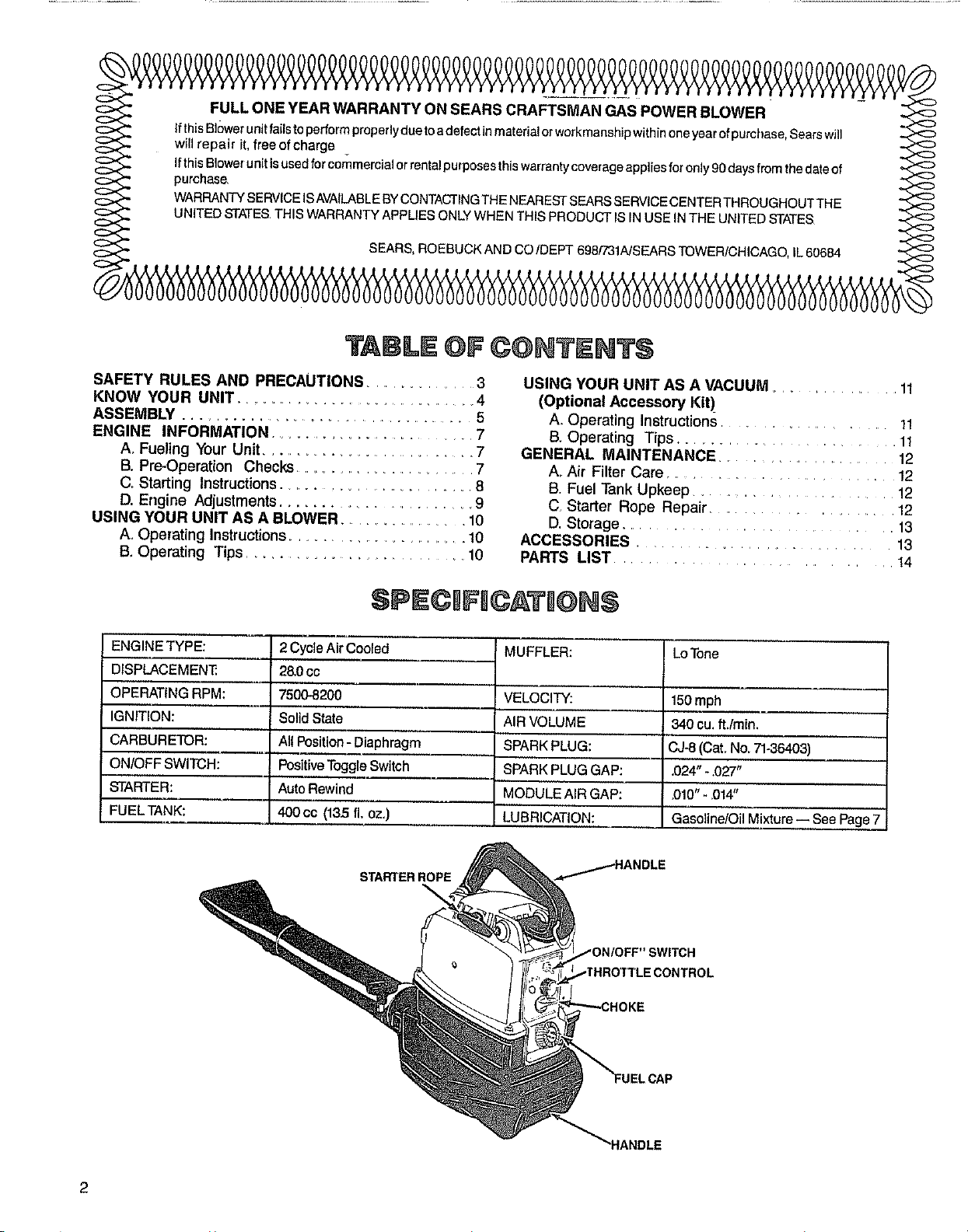
TABLE OF
C@NTEN3=$
SAFETY RULES AND PRECAUTIONS .............. 3
KNOW YOUR UNIT ................................... 4
ASSEMBLY ........................................ 5
ENGINE INFORMATION ............................. 7
A, Fueling Your Unit............................ 7
B, Pre-Operation Checks ........................... 7
C Starting Instructions............................ 8
D. Engine Adjustments.......................... 9
USING YOUR UNIT AS A BLOWER ............... 10
A, Operating Instructions............................. 10
B_Operating Tips ........................... 10
SPECJFI©ATJ@N$
ENGINE TYPE:
DISPLACEMEN31
OPERATING RPM:
IGNITION:
CARBURETOR:
ON/OFF SWITCH:
STARTER:
FUELTANK:
2 Cycle Air Cooled
28.0cc
75008200
Solid State
All Position - Diaphragm
Positive Toggle Switch
Auto Rewind
400cc (13.5 fl, oz.)
USING YOUR UNIT AS A VACUUM
(Optional Accessory Kit)
A Operating Instructions
B. Operating Tips. . .
GENERAL MAINTENANCE
A, Air Filter Care
B Fuel Tank Upkeep
C, Starter Rope Repair
D. Storage.
ACCESSORIES
PARTS LIST
MUFFLER:
VELOCITY:
AIR VOLUME
SPARKPLUG:
SPARKPLUGGAP:
MODULE AIR GAP:
LUBRICATION:
LoTone
150mph
340 cu.ft./min.
CJ-8(Cat,No, 71-36403)
.024"- .027"
.010"- .014"
Gasoline/oil Mixtu're_ see Page7
11
11
12
12
12
12
13
13
14
STARTER ROPE
/HANDLE
;WITCH
2
Page 3
Failure to follow all Safety Rules and Precautions could result in serious personal injury.
A. KNOW YOUR
1 Read your Operator's Manual carefully until you
completely understand and can follow all safety
rules, precautions, and operating instructions
before operating the unit.
2, Restrict your unit to users who understand and
follow all safety rules, precautions, and operating
instructions found in this manual,
PLAN AHEAD
1 Always wear eye protection to prevent recks or
debris from being blown or ricocheting into eyes
and face which can result in loss of vision or
serious personal injury.
2, Always wear a respirator or facemask when
working with the blower in dusty environments.
3, Dress safely in long pants. Do not wear loose
clothing, jewelry, short pants or sandals; or go barefoot
4 Do not operate the unit when you are tired, ill, or
upset; or if you are underthe influence of alcohol,
drugs, or medication.
5 Keepchlldren, bystandersandanimalsawayfrem
the work area, a minimum of 3Ofeet (lO meters),
when starting or operating the unit.
6 Inspectthearaabeforestartingtheunit. Removeall
debris and hard or sharp objects such as rocks, glass,
wire, etc that can be blown or cause damage during
operation. Asa vacuum, the unit is designed topick up
dry material such as leaves, grass, small twigs and bits
of paper. Do notvacuum stones, gravel, metal, broken
giass etc. to avoid severe damage to the impelle_ Do
not attempt to vacuum water or other liquids to
avoid damage to the engine.
C, NANDILI IFU ' = WSTH CAUTaON
1 Eliminate all sources of sparks or flame (including
smoking, open flames, orworkthat can causesparks)
in the areas where fuel ismixed, poured, or stored
2, Mix and pour fuel in an outdoor area; store fuel in
a cool, dry, wen,ventilatedplace; and use an
approved, marked container for all fuel purposes.
3. Do not smoke while handling fuel or while
operating the unit.
4 Do not fill the fuel tank while the engine isrunning
or strapped to the operator.
5 Wipe up all spills before starting the engine.
6_ Move at least 10 feet (3 meters) away from fuel and
fueling site before starting the engine_
D, OPERATE _'OUR UNgT SAFI_LY
1 Stoptheenginebeforeopeningthevacuuminlet
door or attempting to insert or remove the suction
tube. The engine must be stopped and the impeller
blades no longer turning to avoid contact with the
rotating blades
2_ Inspect the entire unit before each use for worn,
loose, or damaged parts. Do not use until the unit is
in proper working order.
3 Keep the outside surfaces free of oil and fuel.
4 Never start or run the engine inside aclosed room
or building. Exhaust fumes contain dangerous carbon
monoxide
5 Do not wear rubber or any other insulated gloves
when using the unit as a vacuum to avoid static
electricity shock.
6 Donotsettheunitonthegreundtostarttheengine
orwhile the engine isrunning. Debris such asgravel,
sand, dust, grass, etc could be picked up by the air
intake and thrown out through the discharge opening,
damaging the unit, property or causing serious
personal injury to bystanders or the operator
7 Avoid dangerous environments. Do not use in
unventilated areas or where explosive vapors or carbon
monoxide build up could be present
8 Do not overreach or use from unstable surfaces such
as ladders, trees, steep slopes, rooftops, etc Keep firm
footing and balance at all times
9 Never place objects inside t he blower tubes; always
direct the blowing debris away from people,
animals, glass, and solid objects such as trees,
automobiles, walls,etc The force ofair cancause rocks,
dirt, or sticks.to bethrown or to ricochet which can hurt
people or animals, break glass or cause other damage
10 Neverplaceanyobjectintheairlntakeopeningas
this could restrict proper air flow and cause damage to
the unit
11 Never run the unit without the proper equipment
attached. When used as a blower, always install a
blowertube When used asa vacuum, alwaysinstallthe
suction tube and collection bag Make sure the
collection bag assembly iscompletely zipped when the
unit isrunning to avoid flying debris
12 Always use the shoulder strap attached to the
collection bag when vacuuming to avoid loss of
controJ
13 Never use for spreading or misting chemicals, fer-
tilizera or toxic substances.
14 Avoid situations that could catch the collection
bag on fire. Do not operate near an open flame Do
not vacuum warm ash from fireplaces, barbecue pits,
brush piles, etc_Do not vacuum discarded cigars or
cigarettes unless cinders are completely cool
15,
Use only for jobs explained in this manual.
E. MA"NTADN YOUR UNliT PROPERLY
1oMaintain the unit according to recommended
procedures.
2, Disconnect spark plug before performing
maintenance except for carburetor adjustmenL
3 Use only genuine replacement parts as recom-
mended by Sears to avoid creating a hazard and/or
voiding your warranty.
4 Check air intake openings and blower tubes fre-
quently, always with the engine stopped. Keep
vents and tubes free of debris which can accumulate
and restrict proper air flow
5 Never make engine adjustments with the unit
strapped to the operator.
6. Drain fuel frem the fuel tank before storing for 30 or
more days.
7 Do not use any accessory or attachment other
than those supplied by Sears for use with this par-
ticular uniL
8 Do not store the unit or fuel in a closed area where
fuel vapors can reach sparks or an open flame from
hot water heaters, furnaces, etc.
9 Store in a dry area out of the reach of children.
3
Page 4
NOW YOUR UNIT
A, _NTRODUCT_ON B. UNPACKONG mNSTRUCTqONS
Your unit is a high performance product designed for
tough jobs.
Special Features Include:
= One-handed Operation
o Direct Drive
o Vibration Dampened Handle
° Weight- 1151bs.
= Convenient Upright Storage
Easy Conversion to Vacuum Capability with the
Optional Accessory Kit #71-79991.
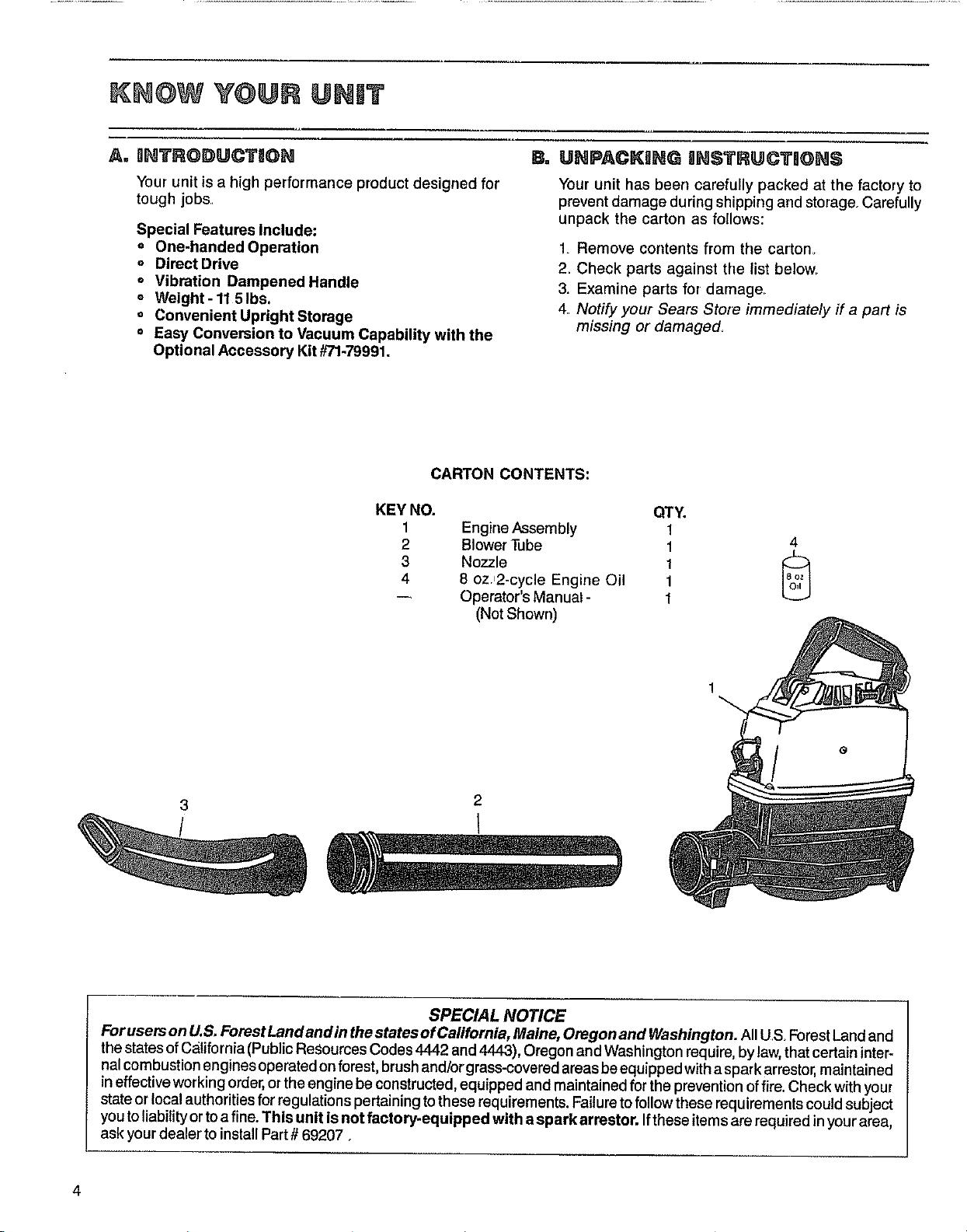
CARTON CONTENTS:
KEY NO. QTY.
1 Engine Assembly 1
2 Blower Tube 1 4
3 Nozzle 1 f_l
4 8 oz.,2-cycle Engine Oil 1
-- Operator's Manual - 1
(Not Shown)
Your unit has been carefully packed at the factory to
preventdamage during shipping and storage, Carefully
unpack the carton as follows:
1 Remove corrtents from the carton_
2. Check parts against the list below
3. Examine parts for damage
4 Notify your Sears Store immediate/y if a part is
missing or damaged,
1
3
/
SPECIAL NOTICE
For users onU.S. Forest Land and in thestates of California, Maine, Oregon and Washington. All US ForestLand and
the statesofCaUfornia(PublicResourcesCodes 4442 and4443), Oregon and Washington require,by law,thatcertaininter-
nalcornbustion enginesoperated onforest, brushand/or grass-coveredareas beequipped withasparkarrestor, maintained
ineffectiveworkingorder,orthe enginebe constructed,equipped andmaintained forthe preventionoffire. Check withyour
state orlocal authoritiesfor regulationspertainingtothese requirements.Failuretofollow these requirementscouldsubject
youtoliability ortoa fine. This unit is not factory-equipped with aspark arrestor. Ifthese items are required inyourarea,
ask yourdealer toinstallPart# 69207.
Page 5
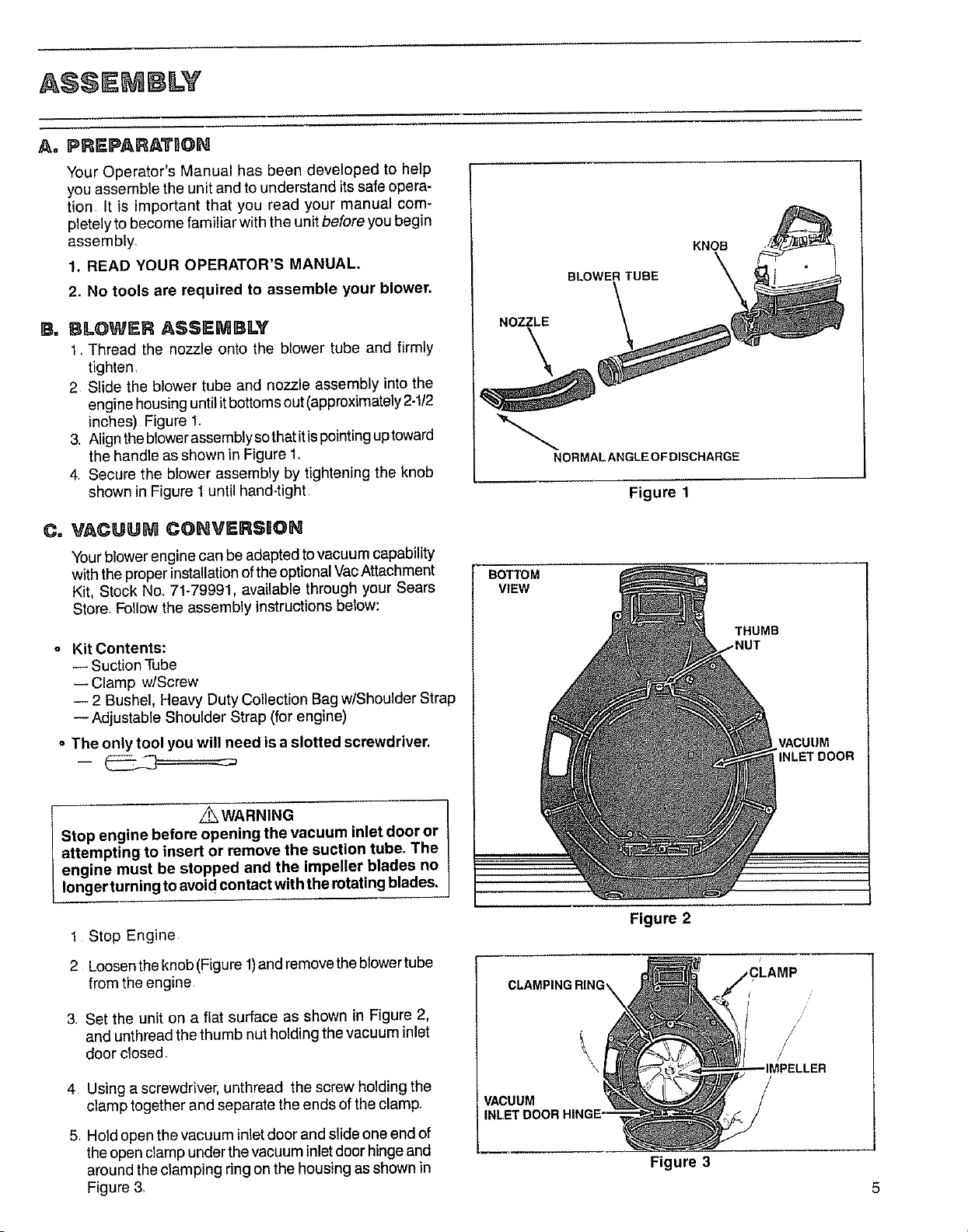
Your Operator's Manual has been developed to help
you assemble the unit and to understand its safe opera-
tion It is important that you read your manual com-
pletely to become familiar with the unit before you begin
assembly,
1. READ YOUR OPERATOR'S MANUAL,
2_ No tools are required to assemble your blower,
KNOB
BLOWER TUBE
B. BLOWER ASSEMBLY
1 Thread the nozzle onto the blower tube and firmly
tighten,
2 Slide the blower tube and nozzle assembly into the
engine housing until it bottoms out (approximately 2-t/2
inches) Figure 1_
3, Align theblower assembly sothat itispointing uptoward
the handle as shown in Figure 1.
4, Secure the blower assembly by tightening the knob
shown in Figure 1 until hand-tight
Co VACUU_ COHVERSION
Your blower enginecan be adapted to vacuum capability
with the properinstallation of the optional Vac Attachment
Kit, Stock No_71-79991. available through your Sears
Store, Follow the assembly instructions below:
o Kit Contents:
-- Suction Tube
-- Clamp w/Screw
-- 2 Bushel. Heavy Duty Collection Bag w/Shoulder Strap
--Adjustable Shoulder Strap (for engine)
o The only tool you will need is aslotted screwdriver.
NOZZLE
\
NORMALANGLEOFDISCHARGE
Figure 1
BOTTOM
VIEW
THUMB
_NUT
VACUUM
INLET DOOR
_WARNING
Stop engine before opening the vacuum inlet door or
attempting to insert or remove the suction tube. The
engine must be stopped and the impeller blades no
longer turning to avoidcontact with the rotating blades.
1 Stop Engine
2 Loosen the knob (Figure 1)and remove the blowertube
from the engine
3 Set the unit on a flat surface as shown in Figure 2,
and unthread the thumb nut holding the vacuum inlet
door closed
4 Using a screwdriver, unthread the screw holding the
clamp together and separate the ends of the clamp,
5 Hold open the vacuum inlet door and slide one end of
the open clamp under the vacuum inlet door hingeand
around the clamping ring on the housing as shown in
Figure 3.
Figure 2
CLAMPING RING_
//
IMPELLER
VACUUM
Figure 3
Page 6
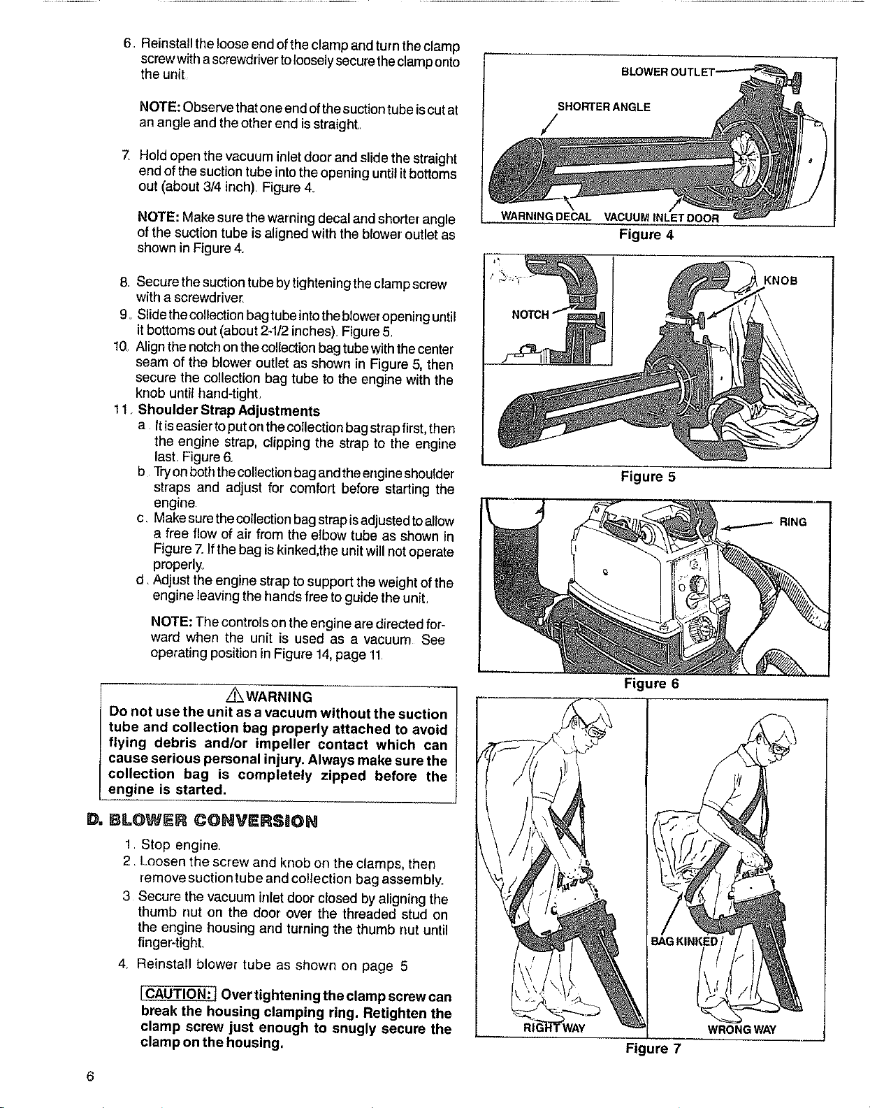
6, Reinstall the loose end of the clamp and turn the clamp
screwwith ascrewdriver to loosely secure the clamp onto
the unit
NOTE: Observe that one end of the suction tube is cut at
an angle and the other end is straight,
7, Hold open the vacuum inlet door and slide the straight
end of the suction tube into the opening until itbottoms
out (about 3/4 inch). Figure 4,
/
NOTE: Make sure the warning decal and shorter angle
of the suction tube is aligned with the blower' outlet as
shown in Figure 4.
8. Secure the suction tube bytightening the clamp screw
with a screwdriver,
9. Slide the collection bagtube into theblower opening until
it bottoms out (about 2-1/2inches). Figure 5,
10, Align the notch on the collection bag tube with the center
seam of the blower outlet as shown in Figure 5, then
secure the collection bag tube to the engine with the
knob until tland-tighL
11 Shoulder Strap Adjustments
a Itiseasiertoput on thecollectionbag strap first, then
the engine strap, clipping the strap to the engine
last Figure 6_
b Tryon boththe collection bagand the engine shoulder
straps and adjust for comfort before starting the
engine
c. Make sure the collection bag strapis adjusted toallow
a free flow of air from the elbow tube as shown in
Figure 7.Ifthe bag is kinked,the unit will not operate
properly.
d Adjust the engine strap to support the weight of the
engine leaving the hands free to guide the unit,
WARNING DECAL VACUUM INLET DOOR
Figure 4
KNOB
Figure 5
RING
NOTE: The controls on the engineare directed for-
ward when the unit is used as a vacuum See
operating position in Figure 14,page 11
Z_WARNING
Do not use the unit as a vacuum without the suction
tube and collection bag properly attached to avoid
flying debris and/or impeller contact which can
cause serious personal injury. Always make sure the
collection bag is completely zipped before the
engine is started.
DoB -OWER CONVERSaON
! Stop engine,
2 loosen the screw and knob on the clamps, ther]
remove suctiontube and collection bag assembly.
3 Secure the vacuum inletdoor closed by aligning the
thumb nut on the door over the threaded stud on
the engine housing and turning tile thumb nut until
fingePtighL
4 Reinstall blower tube as shown on page 5
[CAUTION: ! Over tightening the clamp screw can
break the housing clamping ring. Retighten the
clamp screw just enough to snugly secure the
clamp on the housing.
Figure 6
BAG KINKED
WAY WRONGWA'_/
Figure 7
Page 7

EN@ NE INF@RMATMON
A= FU_L,gNG YOUR UNI;T (See "Specifications, page 2, for location of Fuel Cap.)
1. FUEL MIXTURE
o Your unit is powered by a 2-cycle engine which
requires a fuel mixture of regular, unleaded
gasoline and a high quality engine oil specially
made for 2-cycle, air-cooled engines, The inter-
nal design ofthe 2-cycle enginerequireslubrication
ofmoving parts Lubricationisprovidedwhen you
use the recommended mixtureof gasolineand oil.
• Gasoline must be clean and not over two
months old. After a short period oftime, gasoline
begins tochemicallybreak down and willform com-
pounds that can cause hard starting and damage in
2-cycle engines
o The correct measure of gasolinetoeilisveryim-
portant. Too much oil will foul the spark plug. Toolit-
tle oilwill cause the engine tooverheat and freeze up
• Always mix the fuel thoroughly in a container
since gasoline and oildo not readily combine. Donot
try to mix fuel directly in the fuel tank
USE THE FOLLOWING:
2_
1 GALLON
REGULAR
UNLF_DED _-
-- OR-- _
4. DO NOT USE:
° BIA OIL (Boating Institute of America) --
-- Does not have proper additives for air-cooled,
2_cycle engines and could cause damage
o AUTOMOTIVE OIL --
--Does not have proper additives for 2-cycle
engines and could cause damage
• GASOLINE CONTAINING ALCOHOL
(High Test, Premium or Gasohol) --
--Stiffens critical carburetor fuel metering
eler_ents and causes engine damage from
overheating
--Increases vapor lock (causes hard starting)
-- Attracts water causing corrosion damage
5. IMPORTANT POINTS TO REMEMBER
a, Use only recommended fuel mixtures.
b Eliminate all sources of sparks or flame in the
areas where fuel is mixed, poured, or stored.
There should be no smoking, open flames or
work that can cause sparks.
3. HOW TO MIX FUEL
a Pour one-half of the gasoline into an approved
marked container. Do not try to mix fuel directly
in the h_el tank.
b Add entire measure of 2-cycle Engine OiL
c. Mix.
d. Add remainder of gasoline.
e Mix thoroughly for one mim,te.
B, PRE-OPERATBON CHECKS
Before operating your unit, always:
t. _- CHECK OVER SAFETY RULES AND PRECAU-
TIONS in this Operator's Manual Make certain you
completely understand and follow each one
2. ,-- CHECK THE AIR FILTER.
Clean thefilter before operating the unit, See Figure 15.
c Use an approved, marked container for all fuel
purposes.
d Mix and pour fuel in an outdoor area. Store fuel
in a cool, dry, well-ventilated place. Gasoline
vaporsare harmful to your health and can cause
serious hazards,such as explosionand fire Use a
funnel or spout when pouring fuel
e. Wipe up all fuel spills before starting the
engine.
f. Move at least 10 feet (3 meters) away from fuel
and fueling site before starting the engine.
3. v" CHECK THE UNIT FOR lOOSE BOLTS, NUTS,
OR FITTINGS.
Tighten, repair or replace parts as necessary. Use
only genuine replacement parts;
4. v" CHECK THE FUEL TANK.
Fill with a clean, fresh fuel mixture according to
instructions in fuel mixture section
Page 8

,,,,,, i,
A=STARTING mN$3"RUCI"I]ON$ (Refer to "Specifications," page 2, for location of controls.)
z_WARNING
Hold the unit for starting as shown in Figure 8.Do notset
the unit on the ground to start the engine or while the
engine is running. Debris such as gravel, sand, dust,
grass, etc. could be picked up by the air intake and
thrown out through the discharge opening, damaging
the unit or property or causing serious personal injury
to bystanders or the operator.
1 STARTING PROCEDURE
Hold the unit in the starting position as shown
inFigure 8 Make sure theend of the unit isdirect-
ed away from people, animals, glass and solid
objects
b Move the ignition switch to the "On" position.
Figure9
c Turn the throttle control knob clockwise to
the "Fast" position. Figure 10_
d
Turn choke knob to "On" position. Figure 11
e_
Hold handle with your right hand and pull
starter handle with your left hand until the
engine fires (attempts torun)
BLOWER
STARTING
VACUUM
STARTING
NOTE: Do not let the starter rope snap back
between pulls_Hold the handle and let the rope
rewind slowly
f Turn choke knob to "Half" position and pull
starter handle until engine runs. Figure11.
Allow engine to warm-up as indicated below,
then turn choke knob to the "Off" position.
Figure 11
-- Above40°1:,warm-up 10o20seconds
-- Below40°F, warm-up45.60 seconds
h.
Stop engine by moving ignition switch to the
"Off" position. Figure 9
2. IMPORTANT POINTS
a
When starting the engine, always pull the
starter rope sharply and quickly, but not
more than 10 times to avoid flooding the
engine. If flooding occurs, turn choke to the
"Off" position (Figure 11)and pull starter rope
untilengine starts
b_
Start a cold engine with the choke atthe "On"
position Figure 11
C
Start awarm engine with the choke at the"Off"
position If unit fails to start witilin 2 pulls, move
choke tothe "Half" positiorLFigure 11
Figure 8
IGNITION SWITCH
THROTTLE CONTROL
ON
/
OFF ,
Figure 9 Figure 10
CHOKE KNOB
Figure 11
OFF
8
Page 9

D= ENGBN ADJUSTMSNTS
1. CARBURETOR ADJUSTMENTS
The carburetor has been carefully adjusted at the
factory. Due to changes in altitude and operating
conditions, your carburetor may require adjusting.
Tomake the adjustment follow the procedure below
very carefully:
a PREPARATION
1) Use fresh fuel mix See Fuel Mixture page 7
2) Remove air filter
3) Turn mixture screw clockwise _ until
fully closed, but do not overtighteno Figure
12 Unscrew mixture screw one full turn
counterclockwise
4) Turn Idle Speed Screw clockwise
==,=-_ until it stops Do not overtighten.
Open screw three full turns counterclockwise
/
b IDLE SPEED ADJUSTMENT
1) Start the engine and turn throttle control to
halfway between "Fast" and "Slow"
2 ) Operate the unit for 3 minutes to warm up
engine
3) Turn throttle control counterclockwise
to slow setting
4) Adjust Idle Speed Screw:
Clockwise _ if the engine stalls:
Counterclockwise _ to slow engine
down
5 ) Adjust the Idle Speed Screw until the engine
idles as slow as possible without the engine
stalling
tCAUTION:] The mixture setting is a highly
critical adjustment. If set incorrectly,
permanent damage will occur to the
engine. Do not operate engine at fast
throttle fdr prolonged periods while making
the mixture adjustment.
c MIXTURE ADJUSTMENT:
1) Adjust throttle knob to "Fast" position
2 ) Turn the Mixture Screw slowly clockwise
until the engine speed is reduced
Note position
3) Turn the screw slowly counterclockwise
_===_ Stop when the engine just begins
to run rough
4) Turn the screw slowly the minimum amount
clockwise ==="_ until the engine runs
smoothly
-i
Figure 12
IDLE SPEED
ADJUSTMEN1
NOTE 1: The mixture screw should be in the
range of 3/4 to 1-1/4turns open
NOTE 2: For the best engine performance, it
is better to run a slightly rich mixture setting
(counterclockwise _ )than too lean a
setting
d REPLACE AIR FILTER
2. SPARK PLUG (Cat. No. 71-36403)
Check spark plug periodically and clean or replace
as necessary. After cleaning, reset the electrode gap
to "025,
N ES
9
Page 10

USING YOUR @N T AS L@WER
A. OFE T NG HSTRUCTaON$
1 Read your Operator's Manual, Make certain you
completely understand and can follow all safety rules,
precautions, and operating instructions, before
operating the uniL
2 Always wear eye protection to prevent rocks or
debris from being blown or ricocheting into eyes
and face which can result in loss of vision or
serious personal injury.
3 Always wear a respirator or facemask when work-
mg in dusty environments.
4 Dress safely in long pants. Do not wear loose
clothing, jewelry, short pants or sandals; or go barefoot
5 Check the unit before operation. Look for worn,
loose, or damaged parts Do not use until the unit is in
proper working order
6 Inspect the area before starting unit. Remove all
debris and hard objects such as rocks, glass, wire, etc
that can be blown or cause damage during operation
7 Keepobservers, children, bystanders, andanimals
safely away. Before starting the engine and during
_Pseration, make certain children, animals and
tanders are away from the work area -aminimum of
30 feet (10meters).
8 Check air intake opening and blower tubes fre-
quently, always with the engine stopped. Keep
vents and discharge tubes free of debris which can
accumulate and restrict proper air flow
9 Use the correct operating position. (Figure 13.)Do
not overreach or use from unstable surfaces such as
ladders, trees, steep slopes, roof tops, etc_Keep firm
footing and balance at all times
1Q
Never place objects inside the blower tubes; always
direct the blowing debris away from people,
animals, glass, and solid objects such as trees.
automobiles, walls,etc Theforce ofaircancauserocks.
dirt,orsticks tobethrownorto ricochetwhichmay hurt
people or anirnals, break glass, orcause other damage
ALWAYS USE
"_EYE PROTECTION
USE RESPIRATOR
OR FACEMASK
FOR DUSTY
ENVIRONMENTS
OPERATION
WITHBOTH
HANDLE
CONTROL
PANEL
TO THE _`_
REAR
HANDLE
HANDLES
Figure 13
z_WARNING
Hold the unit for starting as shown in Figure 8. Do not
set the unitontheground tostart theengineorwhilethe
engine is running. Debris such as gravel, sand, dust,
grass, etc. could be picked up by the air intake and
thrown out through the discharge opening, damaging
the unit or property or causing serious personal injury
to bystanders or the operator.
B. OPI RATBNG TIPS
Always work going away from solid objects such as
walls, large stones, automobiles and fences,
2
Clean spaces with corners by starting in corners
and moving outward tostraight areas toprevent an
accumulation ofdebris whichcould fly into face
,
Becareful when working near valuable plants. The
force ofthe air could damage tender plants
4
Direct air flow byadjusting the nozzle.
5,
Run the engine at full throttle for full air power=
6
Vary or reduce the air flow by setting the throttle
knob at any position from "Fast" to "Siowo"
7
Use the handle located on the bottom of the unit
below the control panel when working above the
waistorwhenatwo-handedgripisdesired. Refer
tothe unitdrawing, page 2, and Figure 13,this page
10
z_WARNING
Always wear eye protection to prevent rocks or debris
frern being blown or ricocheting into the eyes and face
which can result in loss of vision or serious personal
injury.
8 -Uses For Your Blower:
a Sweeping debris or grassclippings from driveways,
sidewalks, patios, park, parking lots, barns,
stadiums, etc
b Gathering grass clippings, straw or leaves intopiles
c Fastdrying wet, outdoor areas such as a patio
d Removing debris from corners, around joints and
between bricks
e Blowing light snow from driveways, sidewalks or
patios
Page 11

As a vacuum, the unit is designed topick up dry material
such as leaves,grass, small twigsand bits ofpaper. Donot
attempt tovacuum stones, gravel, metal, broken glass, etc.
to avoid severe damage tothe impeller.
1 Read your Operator's Manual, Make certain you
completely understand and can follow all safety
rules, precautions, and operating instructions,
before operating the unit
2 Always wear eye protection to prevent rocks or
debris from being blown or ricochet;_g into eyes
and face which can result inloss of visionorserious
personal injury.
3 Dress safely in long pants. Do not wear loose
clothing, jewelry, short pants or sandals; or go
barefoot
4 Check the unit before operation, Look for worn,
loose, or damaged parts Do not use until the unit
is in proper working order
5 Inspect the area before starting the unit. Remove
all debris and objectssuch asrocks,glass,wire,large
sticks, etc thatcancause damage during operation
6 Keepobservers, children, bystanders, andanimals
safely away. Before starting the engine and during
operation make certain people and animals are away
from the work area -a minimum of 30 feet (10meters).
7 Check air intake opening and collection bag tube
frequently, always with the engine stopped. Engine
RPM will increase significantly when the suction or
collection bag tube isclogged. Keep vents and tubes
free ofdebris which can accumulate and restrict proper
air flow.
8 Use the correct operating position. (Figure 14)
Do not overreach or use from unstable surfaces
such as ladders, trees, steep slopes, roof tops, etc
Keep firm footing and balance at all times
9 Do not wear rubber or any other insulated gloves
to avoid static electricity shock.
10 Never run the unit without the proper equipment
attached. Always install the suction tube and col-
lectionbag. Make surethe collection bag assembly
iscompletelyzipped when the unit is in use to avoid
flying debris
11 Always use the collection bag and engine shoulder
straps to avoid loss ofcontrol.
Z_WARNING
Do not insert orremove suction tube with engine run-
ning toavoid serious personal injury. Always stop the
engine before unclogging the unit or performing any
maintenance on the collection bag.
COLLECTION
BAG
STRAP
ENGINE
STRAP
CONTROL
"/PANEL
B. OP_RATnNG T_PS
1, Move the unit slowly back and forth over debris
to be vacuumed, Avoid forcing the suction tube into
a pile of debris as this can clog the unit.
2 If the unit becomes clogged:
a. Stoptheengineanddisconnectthesparkplug.Do
not attempt to remove obstructions with engine
running.
b Wait until the impetler has completely stopped turn-
ing, then remove the suction tube
c Carefully reach into the vacuum opening and clear
out debris
Figure 14
3 The collection bag must be properly emptied
,and maintained to avoid deterioration and ob-
structing air flow which will reduce the
performance of the vacuum.
a. Empty the bag after each use. Do not store bag
containing wet grass, leaves, etc
b. Clean the bag after every three uses by turn-
ingthe bag inside out after initial emptying and
vigorously shaking out dust and excess debris
c. Wash the bag once a year
1) Turn bag inside out
2). Hang up
3). Hose down thoroughly
4). Hang to dry 11
Page 12

MA NTENAN©E
Ao AIR FILTER CARE
A dirty air filter decreases engine performance and
increases fuel consumption_
Clean the Air Filter:
• Frequently,
o Always clean after 5 tanks of fuel or 5 hours of
operation, whichever is less.
Follow these steps:
1 Remove the air filter (located above the control
panel; see Figure 15)
2 Wash in soap and water
ICAUTION:I Do not clean filter in gasoline or
other flammable solvent to avoid creating a fire
hazard.
& Squeeze filter dry
4 Add a small amount of oil to coat the filter,
NOTE: Avoid soaking the filter with oil
5 Squeeze out excess oil
6 Replace the air filter.
NOTE: Make sure the filter is properly fitted into the
housing, paying particular attention to the corners.
Bo FUEL TANK UPKEEP
Never use gasoline that is more than 2 months old
in a fuel mixture. Gasoline begins to break down after
a short period of time and will form compounds that
cause hard starting and damage in 2-cycle engines
1 Inspect the unit for fuel leaks each time it is
used. Repair or replace parts as necessary
2 Always begin operation with a clean, fresh
mixture of fuel.
3 Drain all fuel from the unit or allow unit to run
out of fuel before storing for 30 or more days.
C. STARTER ROPE REPAIIR
• Repair the starter rope if the rope breaks next to
the pulley.
o Replace the starter rope if the rope breaks more
than 2-3 inches away from the pulley as the rope
will be too short to repair properly.
Z_WARNING
Always wear eye protection when servicing the starter
rope. The recoil spring, located beneath the pulley, is
under tension. Ifthe spring pops out, serious personal
injury can result.
Figure 15
FAN HOUSING --_.
REMOVE
SCREWS
F
SPARK PLUG WIRE
12
° To repair or replace:
1 Disconnect the spark plug wire and remove the 6
screws from the fan housing.Figure 16,
2 Separate the far] housing completely from the
shroud
Figure 16
Page 13

3
Ifthe starter rope is notbroken, release the spring's
tension by pulling about 10inches of rope from the
pulley and catching the rope inthe notch as shown
Figure 17 If the rope is broken, remove the broken
piece.
NOTE: The tension on the starter spring will be
released ifthe rope is broken
4_ Remove screw and pulley very carefully, Figure 17
The recoil spring which lies beneath the pulley
must stay in the housing, flat against the bot-
tom. If the spring is disturbed, it will require con-
siderable time and effort to reinstall. Twist the
pulleygentlycounterclockwise _ asyoupull
up to release the spring
5 Move away from the fueltank and melttheend ofthe
rope to go into the pulley`
6 Allow the melted end to drip once; then while the
rope is still hot, pull the melted end through a ragto
obtain a smooth, pointed end
7 Insert rope through the rope exit hole in the fan
housing
8 Snake rope inside the pulley, then through topside
pulley hole by pushing the rope from the underside
holewith a small round object such as a Phillips
screwdriver. See Insert, Figure 18
9 Wrap rope counterclockwise _ around
pulley ratchet and tuck loose end back under rope
leaving a 3/8 to 1/4inch tail Figure 18 Pull tightly
l& Wind all but about 10 inches of the rope counter
clockwise _ around pulley
11_ Replace pulley inthe housing Be sure the pulley is
all the way down and the spring is secured
12. Replace and tighten pulley screw Figure 17.
13 Hold the 10 inch slack in the rope and catch rope
in pulley notch. Figure 19
14 Hold the rope taut and make 2 complete turns
of the pulley counterclockwise _ to place
tension on the pulley Hold the pulley to retain
tension
I5. Align pulley notch with rope exit hole, pull starter
handle to the full extent of the rope and allow the
rope to slowly wind around the pulley
16 Reinstall the fan housing tothe shroud.
;HET
Figure 17
SCREWDRIVER ._" / /
/
__ Figure 18
\
NOTCH
Figure 19
D, STORAGE
1 Clean the unit before storing. Pay particular atten-
tion to the air intake area,keeping itfreeof debris Use
a mild detergent and sponge to clean the plastic
surfaces
A©©A$$@RBA$
VACUUM ATTACHMENT K_T ..................
2-CYCLE ENG_IRE OHL .......................
SPARK PLUG ...........................
SHOULDER STRAP I_BT (for Engine) ............
2 Do not store the unit or fuel in aclosed area where
fuel vapors can reach sparksor an open flame from
hot water heaters, furnaces, etc.
3. Store in a dry area out of reach of childrenr
mmwwmwmlmmwm=_lm
====B=l=mm.mm#_
............ 71-79991
....... 7%36555
illll.......
mmmm_m=#==m=_#=
............ 7t-85783
13
Page 14

SEARS BLOWER PARTS UST _ MODEL 358.796920
Figure 1
10
11
2
.j 15 16
/
101
14
13
31
32
102
19
25
2O
33
34
35
33
o
38
43 41 40
42
38
14
Page 15

SEARS BLOWI=R PARTS LOST -- MODEL 358.796920
Figure 1
KEY PART CITY, DESCRIPTION QTY, DESCRIPTION
NOo NO. NO. NO,
1 10828 1 Ass'y - Handle(Incl #2) 31 26776 1 Deflector- Heat
2 15635 2 Screw - 10- 14 x 11116Bind, Hd- 32 10824" 1 Shroud - (Incl #12 &45)
Handle 33 10835 1 Ass'y- Blower Hsg (IncL 9of#38)
5 24256 3 Isolator - Handle 34 94215 1 Impeller
6 15343 1 Spacer - Isolator (Front) 35 15661 1 Screw - 10- 14 x 88 -
7 26163 6 Cup - Isolator Blower Hsg/Inlet Door
8 15629 2 Washer #8 - Front 37 15064 1 Nut - 10- 24
g 15628 2 Screw -8 - 32 x 7/16Rind Hd - 38 15367 10 Screw - 10- !4 x 3/4
Fan Hsg/Crankcase Pivot Pin/Blower Hsg
10 15561 2 Screw- 12- 11x2 39 15644 1 Nut - Impeller
11 15342 2 Spacer - Isolator (Rear) 40 15441 ! Washer +Conical - Impeller
12 32091 * 1 Bearing-Ball (Shroud) 42 15632 4 Screw - 1/4- 20 x 7/8 +
13 15678 2 Screw - 10+24 x 5/8 Bind Hd + Blower Hsg/Shroud
14 24371 1 Air Filter
15 15676 4 Screw- 10 - 24x 7/8 -Fan Housing 44 15168 4 Screw- 10+24 x5/8-
16 15677 4 Washer - Fan Hsg Shroud/Crankcase
17 10821 1 Fan Housing 45 1516 1 Retainer-Bearing-Shroud
18 42023 1 Spring - Starter Pulley 46 15667 1 Spring - Tension (Right)
19 26780 1 Baffle - Air 47 15647 ! Pin - Pivot
20 28626 1 Pulley Starter 48 15672 1 Spring - Tension (Left)
21 15479 1 Screw +10 - 3/4 Hex Hd +Pulley 49 94241 1 Ass'y - Inlet Door
22 15123 1 Washer - Starter Pulley 50 15638 1 Screw - 1/4x20 1/2- Retainer
23 15544 4 Screw - 10 x3/8 Pan Hd - 51 !5637 1 Retainer +Fuel Tank
24 22289 1 Rope (3 ft ) 53 91678 1 Ass'y - Fuel Pick-up
25 26735 1 Handle - Starter Rope 54 21058 1 Line - Fuel - Tank
27 15664 1 Bolt - 1/4- 20 x 1-1/2-Clamp 56 10729 1 Ass'y - Fuel Cap w/Retainer
28 94222 1 Clamp - Blower Tube 57 10615 1 Ass'y -Fuel Tank
29 94242 ! Knob - Clamp (Incl #53, 54 & 56)
30 15636 3 Screw -10 - Heat Deflector DECALS
Fan Hsg/Crankcase 43 15682 4 Washer - Blower Hsg/Shroud
Air Baffle 52 26781 1 Cushion - Fuel Tank
KEY PART
41 15626 1 Washer- Flat- Impeller
101 26778 1 Decat- Instruction
102 26777 2 Decal - (Left & Right) Fan
Housing
103 26925 1 Deca_- Warning-Blower Hsg
Key Nos+Excluded: #3, 4, 26, 36 & 55
*When removing or installingthe bearing (#32091), the area of the shroud (#10824) receiving the bearing must be heated to
approximately 3000E to avoid damaging the shroud
15
Page 16

SEARS BLOWER PA_$ L_S_=-- MODEL 358.796920
14
o/
29
15
28
22
21
18
Figure 2
19
21
/
5
7
8
22
13
12
11
16
56
26
12
72
52
53
SPARK
ARRESTOR
KIT
3
/
55
Page 17

SITARS BLOWER PARTS LIST -- MODEL 358.796920
Figure 2
KEY PART
NO. NO.
1 12112
2 19111
3 26681
4 15162
5 15239
6 26949
7 10809
8 24361
9 24903
10 69203
11 94219
12 94218
13 94243
14 626605
15 23817
18 26765
19 32057
20 15351
21 32058
22 1O819
23 19059
26 15377
27 15126
28 15168
29 39111
30 15127
31 24438
32 19108
33 191O5
34 15241
35 23367
36 26818
37 19115
38 25472
39 21056
40 26797
41 26772
QTY, DESCRIPTION KEY PART
1 Cylinder 42 15676 1 Screw* 10-24x7/8-
1 Gasket- Cylinder Carburetor
2 Ring - Piston 28cc 43 35196 1 Carburetor
2 Retainer - Wrist Pin 44 15254 1 Washer - Wave -Carburetor
2 Screw - 1/4- 20 x 3/4- 45 15673 1 Spacer - Carburetor
Hex Soc Hd.* Cylinder 46 15630 1 Screw- 10- 24 x 2 3/8- Carb.
1 Diffuser - Muffler Shoulder
1 Ass'y - Body-Muffler 47 15654 1 Ring - External Retaining
1 Cover - Muffler Throttle
2 Spring - Muffler Attachment 48 15147 1 Washer-Wave-Throttle
1 Piston Kit (IncL#3, 4 & Pin) 49 15407 1 Screw - 8 -32 x 5/16Pan Hd. -
1 Shaft - Arbor Choke Knob
2 Coupling - Shaft 50 26773 1 Actuator - Choke
1 Coupling - Plastic 51 15147 1 Washer - Wave -Choke
1 Nut - Flywheel - 5/16 x 24 52 26764 1 Cover - Carb_Case
2 Spring - Starter Dog 53 23807 1 Knob -Choke
1 Ass'y-Crankshaft&Rod 54 15675 4 Screw- 8- 18x 5/8 Phil.
1 Bearing - Wrist Pin 55 15660 1 Screw 10- 14x 3/8 -Throttle
2 Washer-Thrust-Crankcase 56 15658 1 Washer- Flat Throttle
2 Bearing - Crankshaft 57 15614 1 Knob -Throttle
1 Crankcase Ass'y. 58 23575 1 Nut -Grounding Switch
(Incl. #21& 23) 59 24569 1 Washer - Ground
2 Seal - Crankcase 60 26766 1 Switch Toggle
1 Washer - Coupling (IncL #58,59, 62, 63)
1 Key- Flywheel 61 26771 1 Ass'y -Throttle Wire
4 Screw - 10- 24 x 5/8 Fil. Hd. 62 26950 1 Wire - Ignition
1 Flywheel Assembly (Incl. #15) 64 24435 1 Grommet - Plug Wire
1 Washer* Flywheel 65 15128 2 Screw_ 8-32 x 3/4 FiL Hd -
1 Seal - Carburetor Case 68 3933 1 Connector - Spark Plug Lead
1 Screw- 6 - 19x 5/16- Pan Hd. - 69 3934 1 Boot - Spark Plug
1 Washer- Reed Valve Screw 71 39103 1 High Tension - Lead Assembly -
1 Case - Carburetor (IncL #68,69, &70)
1 Gasket -Carburetor 72 30054 1 Sealant - Crankcase -
1 Fitting - Fuel Line (Not Supplied With Unit)
1 Line - Fuel -Carburetor 73 69207 1 Spark Arrestor-Kit
1 Guide Plate - Choke (Not Supplied With Unit)
Crankcase 63 26829 1 Wire - Ground
1 Reed Valve Ignition Module
1 Gasket -Carburetor Case to 66 39124 1 Ignition Module
Crankcase 67 STD360946 1 Spark Plug (CJ-8) -(CaL No. 71-36403)
Reed Valve 70 39082 1 High Tension Lead Wire
1 Shutter- Choke
NO. NO. QTY. DESCRIPTION
Key Nos. Excluded: #16, 17, 24, & 25
17
Page 18

S_=AR$ BLOWER PA_S LaST -- MODEL 358.796920
CARBURETOR ASSEMBLY -- #35196
Figure 3
18
KEY PART
NO. NO_ DESCRIPTION
1
35197
2
35015
3
35132
4
35156
5
35138
7
35200
8
35198
9
35162
11
35017
12
35191
13
35164
14
35166
15
35178
18
35007
19
35008
20
35139
21
35031
22
35028
23
35016
24
35151
25
35014
26
35003
27
35021
35199
35186
Valve Throttle
Screw-Throttle Valve
Shaft Assembly-Throttle
Idle Speed Screw
Spring-Throttle Return
Spring-High Speed Mixture Needle
Needle-High Speed Mixture
*Plug-5/16 Dia Welch
Screw-Pump Cover
Cover-Fuel Pump
+" Gasket-Fuel Pump
+* Diaphragm-Fuel Pump
Screen-Fuel inlet
Ring-Throttle Retainer
"Valve-inlet Needle
*Spring-Metering Lever
•Lever-Metering
"Pin*Metering Lever
•Screw-Metering Lever Pin
+" Gasket-Metering Diaphragm
+" Diaphragm*Metering
Cover-Metering Diaphragm
Screw,_ssembly-Metering Cover
Kit-Repair (includes parts marked*)
Kit-Gasket/Diaphragm (includes parts marked +)
Page 19

SEARS BLOWER PARTS LaST -- MODEL 358.796920
Figure 4
1
/
VACUUM KIT #71-79991 (Optional Accessory Kit)
KEY NO.
1
2
3
PART
QTY. NO. DESCRIPTION
1 94225 Nozzle - Blower
1 94224 Tube- Blower (Upper)
1 66517 Operator's Manual
3
Ol
KEY NO.
1
2
3
4
5
6
101
PART
QTY. NO.
1 94394
1 94231
1 94227
1 15671
1 94230
1 94232
Decal
1 26937
\
4
DESCRIPTION
Strap-Shoulder-Engine
Tube-Collection Bag
Bag-Collectionw/Strap
Strap-Tie
Clamp-Suction Tube
Tube-Suction
Decal - SuctionTube
19
Page 20

operator's
manual
The Model Number wilt be found under the handle with the Serial
Number Always mention the Model Number when requesting service
or repair phrts for your' unit,
All parts listed herein may be ordered from any Sears Service Center
and most Sears Stores
WHEN ORDERING REPAIR PARTS ALWAYS GIVE THE FOLLOWING
INFORMATION AS SHOWN IN THIS LIST
1 The PART NUMBER
3 The PART DESCRIPTION
MODEL NO
358.796920
How to Order
Repair Parts
2 The MODEL NUMBER
358.796920
If the parts you need are not stocked locally, your order will be elec-
tronically transmitted to a Sears Repair Parts Distribution Center for
expedited handling
4 The NAME OF ITEM --
GAS POWER BLOWER
When you buy merchandise from
Sears you get an extra something
that nobody else can 0ffe! Sears
Service
Across town or across the country,
Sears Service follows you, pro-
viding trustworthy, competent ser-
vice technicians using only Sears
specified factory parts
SEARS SERVICE
IS AT YOUR SERVICE
66517-3-24085-1-24085
Your Sears Merchandise takes on added value when you discover
that Sears has Service Units throughout the country. Each is staffed
by Sears-Trained, professional technicians using Sears approved
methods.
Sear bu -k an . _ 4 .S.A.
s, Roe c d Co, C licago, Ill. 6068 U
 Loading...