

Page 1

operator's
manual
MODEL NO.
358.796131-26.2cc
___WARNING:
Carefully read and follow
Safety Rules, Precautions
and Operating Instructions.
Failure to do sO-can result in
serious personal injury.
Sold by Sears, Roebuck and Co., Chicago, Ill. 60684 U.S.A.
RnFT,SMn
GAS WEEDWACKER ®
Fuel Mix 16:1 2 Cycle Engine
• Assembly • Maintenance
• Operation • Repair Parts
Always Wear Eye Protection During Operation
66706-1-34385-1-34485 PRINTED IN U.S.A.
Page 2
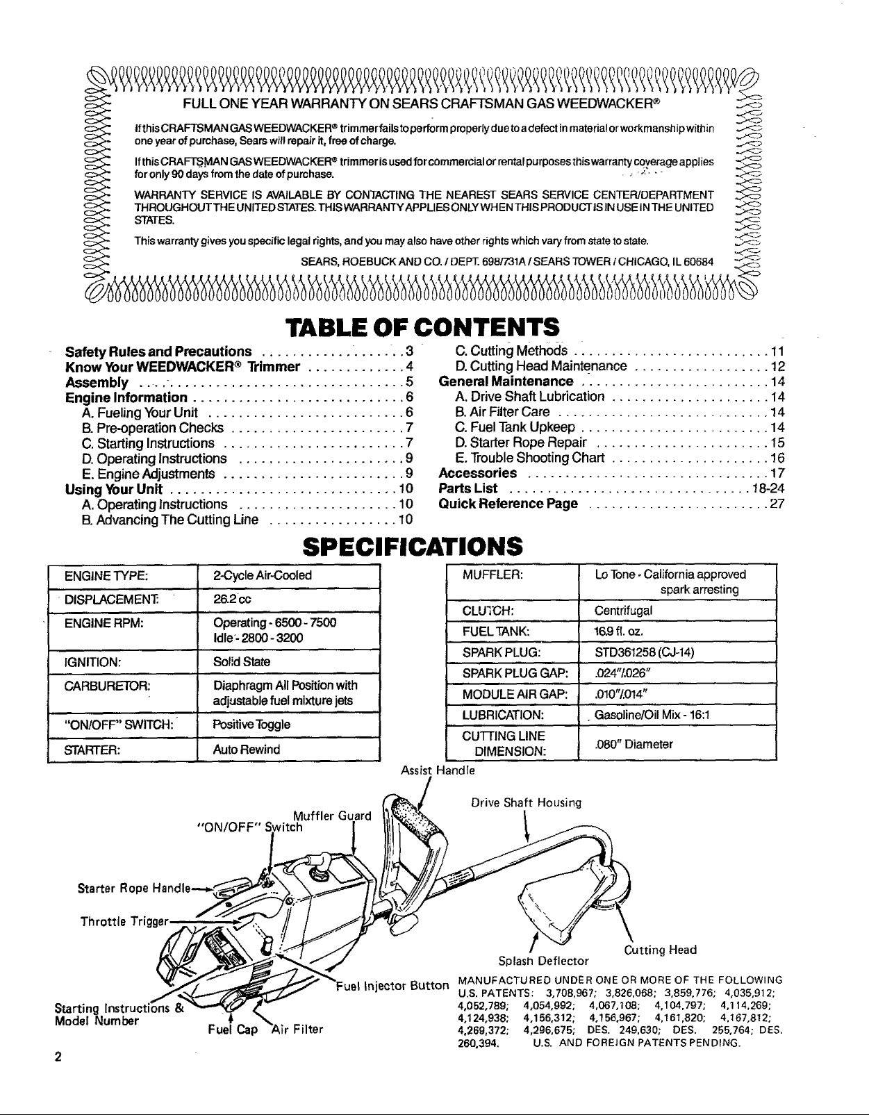
FULL ONE YEAR WARRANTY ON SEARS CRAFTSMAN GAS WEEDWACKER
Ifthis CRAFTSMAN GAS WEEDWACKER trimmer fails toperform properlydue to adefect inmateria! or workmanshipwithin
one year ofpurchase, Sears will repair it, free of charge.
_fthis _RAFTS"_AN GAS _EE _A_KER_ trimmer is usedf_r c_mmercia_ _rrentaI purp_ses thiswarranty c_v`erage app_ies
for only g0 days from the date of pumhase. , -, --" "-
WARRANTY SERVICE IS AVAILABLE BY CONTACTING THE NEAREST SEARS SERVICE CENTER/DEPARTMENT
THROUGHOUT THE UNITED STATES.THIS WARRANTYAPPLIES ONLY WH ENTHIS PRODUCTtS IN USE INTHE UNITED
STATES.
This warranty gives you specific legal rights, and you mayalso have other rights which vary from state to state.
/ , - • , ..... • t t , , • / , i ,
®
SEARS, ROEBUCK AND CO. / DEPT. 698/731A / SEARS TOWER / CHICAGO, IL 60684
TABLE OF CONTENTS
Safety Rules and Precautions ................... 3
Know Your WEEDWACKER ® Trimmer ............. 4
Assembly - 5
Engine Information ............................ 6
A. FuelingYourUnit .......................... 6
B. Pre-operation Checks ....................... 7
C. StartingInstructions ........................ 7
D.Operating Instructions ...................... 9
E. Engine Adjustments ........................ 9
Using YourUnit .............................. 10
A. OperatingInstructions ..................... 10
B.AdvancingThe Cutting Line ................. 10
C. Cutting Methods .......................... 11
D.Cutting Head Maintenance .................. 12
General Maintenance ......................... 14
A. Drive Shaft Lubrication ..................... 14
B.Air Filter Care ............................ 14
C. Fuel Tank Upkeep ......................... 14
D.Starter Rope Repair ....................... 15
E. Trouble Shooting Chart ..................... 16
Accessories ................................ 17
Parts List ................................ !8-24
Quick Reference Page ........................ 27
SPECIFICATIONS
ENGINE"I_PE: 2-CycleAir-Cooled
DISPLACEMEN'£ 26.2cc
ENGINERPM: Operatingo6500- 7500
Idle-2800- 3200
IGNITION: SolidState
CARBURETOR: DiaphragmAllPositionwith
adjustablefuelmixturejets
"ON/OFF' SWITCH: PositiveToggle
STARTER: Auto Rewind
Muffler Guard
Starter Rope
Throttle Trigger
Starting Inst
Model Number
"ON/OFF" Switch
Fuel Cap Filter
Assist Handle
Injector Button
MUFFLER: LoTone-Californiaapproved
spark arresting
CLUTCH: Centrifugal
FUELTANK: 16.9fl. oz.
SPARKPI"UG: STD3"6i258((_J-14)
SPARKPLUGGAP: .024"/.02t_"
MODULEAIRGAP: ,010't/,014 "
LUBRICATION: . Gasoline/OilMix-16:1
cUTrlNG LINE
DIMENSION:
Drive Shaft Housing
Splash Deflector
MANUFACTURED UNDER ONE OR MORE OF THE FOLLOWING
U.S. PATENTS: 3,708,967; 3,826,068; 3,859,776; 4,035,912;
4,052,789; 4,054,992; 4,067,!08; 4,I04,797; 4,114,269;
4,124,938; 4,156,312; 4,156,967; 4,161,820; 4.167,812;
4,269,372; 4,296,675; DES. 249,630; DES. 255,764; DES.
260.394, U.S. AND FOREIGN PATENTS PENDING.
.080"Diameter
Cutting Head
Page 3
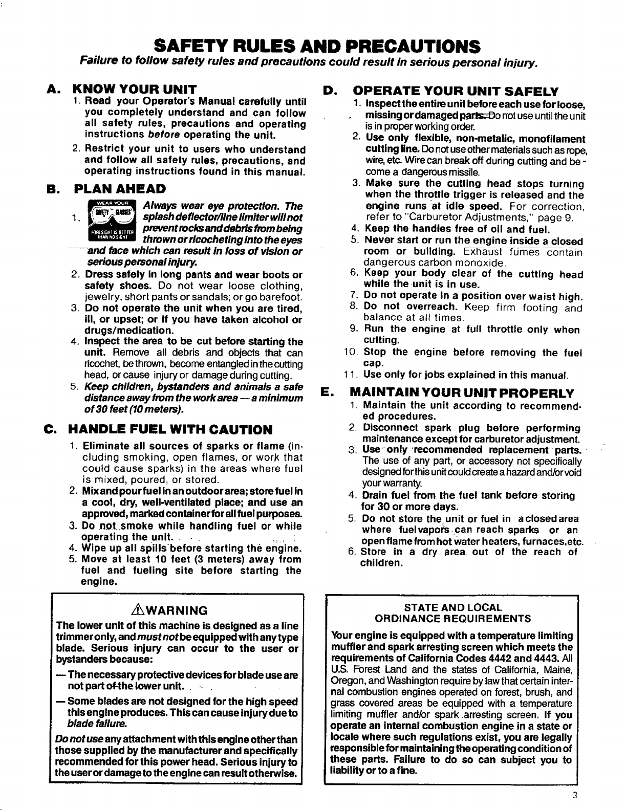
SAFETY RULES AND PRECAUTIONS
Failure to follow safety rules and precautions could result in serious personal injury.
AI
KNOW YOUR UNIT
1. Read your Operator's Manual carefully until
you completely understand and can follow
all safety rules, precautions and operating
instructions before operating the unit.
2 Restrict your unit to users who understand
and follow all safety rules, precautions, and
operating instructions found in this manual.
B. PLAN AHEAD
Always wear eye protection. The
1. splash deflector/line iimiter willnot
prevent rocksand debris frombeing
--and face which can result In loss of vision or
serious personal injury.
2. Dress safely in long pants and wear boots or
safety shoes. Do not wear loose clothing,
jewelry, short pants or sandals; or go barefoot.
3. Do not operate the unit when you are tired,
ill, or upset; or if you have taken alcohol or
drugs/medication.
4. Inspect the area to be cut before starting the
unit. Remove all debris and objects that can
ricochet,be thrown,become entangledinthecutting
head, or cause injuryor damage duringcutting.
5. Keep children, bystanders and animals a safe
distance away from the work area -- a minimum
of 30 feet (10 meters).
C. HANDLE FUEL WITH CAUTION
1. Eliminate all sources of sparks or flame (in-
eluding smoking, open flames, or work that
could cause sparks) in the areas where fuel
is mixed, poured, or stored.
2. Mix and pour fuel in an outdoor area; store fuel in
a cool, dry, well-ventilated place; and use an
approved, marked container for allfuel purposes.
3. DO .n_oLsmoke while handling fuel or while
operating the unit.
4. Wipe up all spills before starting the eng'ine.
5. Move at least 10 feet (3 meters) away from
fuel and fueling site before starting the
engine.
thrown or ricocheting into the eyes
De
OPERATE YOUR UNIT SAFELY
1. Inspect the entire unit before each use for loose,
missing or damaged parl_Do not useuntil the unit
isin properworkingorder.
2. Use only flexible, non-metalic, monofilament
cutting line. Do notuseothermaterialssuchas rope,
wire,etc. Wirecan break offduring cutting and be -
come a dangerous missile.
3. Make sure the cutting head stops turning
when the throttle trigger is released and the
engine runs at idle speed. For correction,
refer to "Carburetor Adjustments," page 9.
4. Keep the handles free of oil and fuel.
5. Never start or run the engine inside a closed
room or building. Exhaus[ _LJmes contain
dangerous carbon monoxide.
.
Keep your body clear of the cutting head
while the unit is in use.
7.
Do not operate in a position over waist high.
8.
Do not overreach. Keep firm footing and
balance at att times.
9.
Run the engine at full throttle only when
cutting.
10.
Stop the engine before removing the fuel
cap.
11.
Use only for jobs explained in this manual.
El
MAINTAIN YOUR UNIT PROPERLY
1. Maintain the unit according to recommend.
ed procedures.
2. Disconnect spark plug before performing
maintenance except for carburetor adjustment.
3. Use only recommended replacement •parts.
The use of any part, or accessory not specifically
designed forthis unit couldcreate ahazardand/or void
your warranty.
4. Drain fuel from the fuel tank before storing
for 30 or more days.
5. Do not store theunit or fuel in a closed area
where fuelvaporsocan reach sparks or an
open flame from hot water heaters, furnaces,etc.
6. Store in a dry ar.ea out of the reach of
children.
i_WAR NI NG
The lower unit of this machine is designed as a line
trimmer only, andmust not be equipped with any type
blade. Serious injury can occur to the user or
bystanders because:
The necessary protective devices for blade useare
not part of-the lower unit.
-- Some blades are not designed for the high speed
this engine produces. This can cause Injury due to
blade failure.
Do not use any attachment with this engine other than
those supplied by the manufacturer and specifically
recommended for this power head. Serious injury to
the user or damage to the engine can resultotherwise,
STATE AN D LOCAL
ORDINANCE REQUIREMENTS
Your engine is equipped with a temperature limiting
muffler and spark arresting screen which meets the
requirements of California Codes 4442 and 4443. All
U.S. Forest Land and the states of California, Maine,
Oregon,and Washingtonrequire bylaw thatcertaininter-
nal combustion engines operated on forest, brush, and
grass covered areas be equipped with a temperature
limiting muffler and/or spark .arresting screen. If you
operate an internal combustion engine in a state or
locale where such regulations exist, you are legally
responsible for maintaining the operating condition of
these parts. Failure to do so can subject you to
liability or to a fine.
Page 4
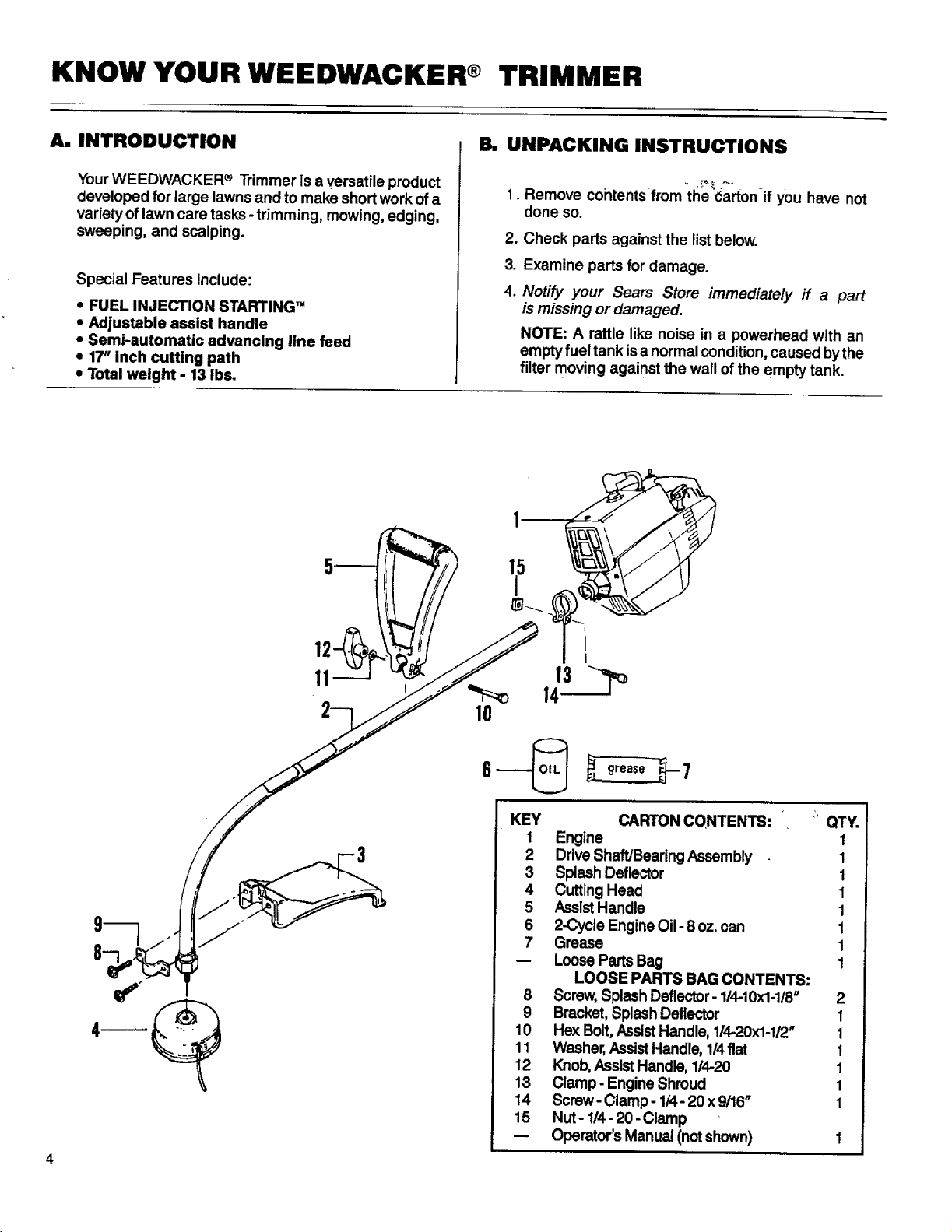
KNOW YOUR WEEDWACKER ® TRIMMER
A. INTRODUCTION
Your WEEDWACKER ® Trimmer is a versatile product
developed for large lawns and to make short work ofa
variety of lawn care tasks -trimming, mowing, edging,
sweeping, and scalping.
Special Features include:
• FUEL INJECTION STARTING"
• Adjustable assist handle
• Semi-automatic advancing line feed
• 17" inch cutting path
• Total weight -13 ibs. -
B. UNPACKING INSTRUCTIONS
°
Remove contentsfrom the Carton if you have not
done so.
,
Check parts against the listbelow.
3
Examine parts for damage.
4
Notify your Sears Store immediately ff a part
is missing or damaged.
NOTE: A rattle like noise in a powerhead with an
emptyfuet tank isanormal condition,caused by the
filter moving against the wall of the empty tank.
..
10
,,'L__m
KEY
1
Engine 1
2
DriveShaft/Bearing Assembly 1
3
SplashDeflector 1
4
CuttingHead 1
5
AssistHandle 1
6
2-Cycle Engine Oil - 8 oz. can 1
7
Grease 1
LooseParts Bag 1
8
Screw, SplashDeflector- 114-10x1-1/8" 2
9
Bracket,Splash Deflector 1
10
Hex Bolt,AssistHandle, 114-20x1-1/2" 1
11
Washer,AssistHandle, 1/4fiat 1
12
Knob, AssistHandle, 114-20 1
13
Clamp - Engine Shroud 1
14
Screw- Clamp - 1/4- 20 x 9/16" 1
15
Nut - 1/4- 20 -Clamp
Operator's Manual (not shown) 1
CARTON CONTENTS: '" QTY.
LOOSE PARTS BAG CONTENTS:
Page 5
ASSEMBLY
A. PREPARATION
Your Operator's Manual has been developed to help
you assemble the unit and to understand its safe opera-
tion. It is important that you read your manual com-
pletely to become familiar with the unit before you begin
assembly.
I. READ YOUR OPERATOR'S MANUAL.
2. Tools you will need:
a:
/
Z" 1-1/4inch Wrench
7116inch Wrench "
3/8 inch Wrench
or
Z
Adjustable Wrench
b. _ _
_ Slotted Screwdriver
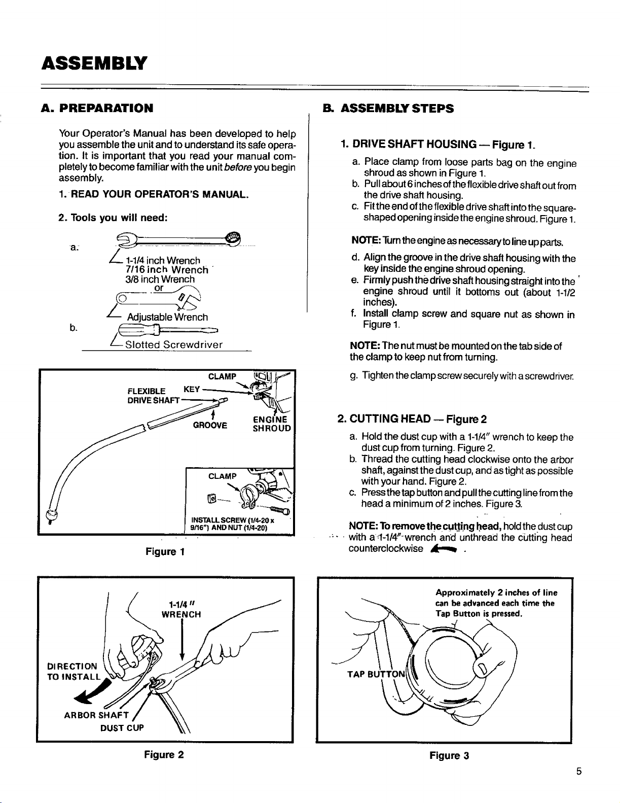
CLAMP ___J ._
ASSEMBLYSTEPS
1. DRIVE SHAFT HOUSING -- Figure 1.
a. Place clamp from loose parts bag on the engine
shroud as shown inFigure 1.
b. Pull about 6inches ofthe flexible drive shaft out from
the drive shaft housing.
c. Fitthe end of the flexible drive shaft intothesquare-
shaped opening insidethe engine shroud. Figure 1.
NOTE: Turntheengine as necessarytolineupparts.
d. Alignthe groove in the drive shaft housing with the
key inside the engine shroud opening.
e. Firmly push the drive shaft housing straight into the"
engine shroud until it bottoms out (about 1-1/2
inches).
f. Install clamp screw and square nut as shown in
Figure 1.
NOTE: The nutmust be mountedon thetabside of
the clamp to keepnut from turning.
g. Tighten the clamp screw securerywith ascrewdriver.
DRIVE SHAFT _ _
.o'ovo
DI RECTI ON
TO INSTALL
Figure 1
1-1/4"
WRENCH
2. CUTTING HEAD -- Figure 2
a. Holdthe dust cup with a 1-1/4"wrench tokeep the
dust cup fromturning. Figure 2.
b. Thread the cutting head clockwise onto the arbor
shaft, against the dust cup, and as tight aspossible
with your hand. Figure 2.
c. Press the tapbutton and pullthe cutting linefrom the
head a minimum of 2 inches. Figure 3.
NOTE: Toremove the cu_ing bead, hold thedust cup
.... with at-l/4"-wrench and unthread the cutting head
counterclockwise &[_,_ .
Approximately2inchesof line
canbeadvanced each timethe
L.
ARBOR SHAFT
DUST CUP
Figure 2
Figure 3
Page 6
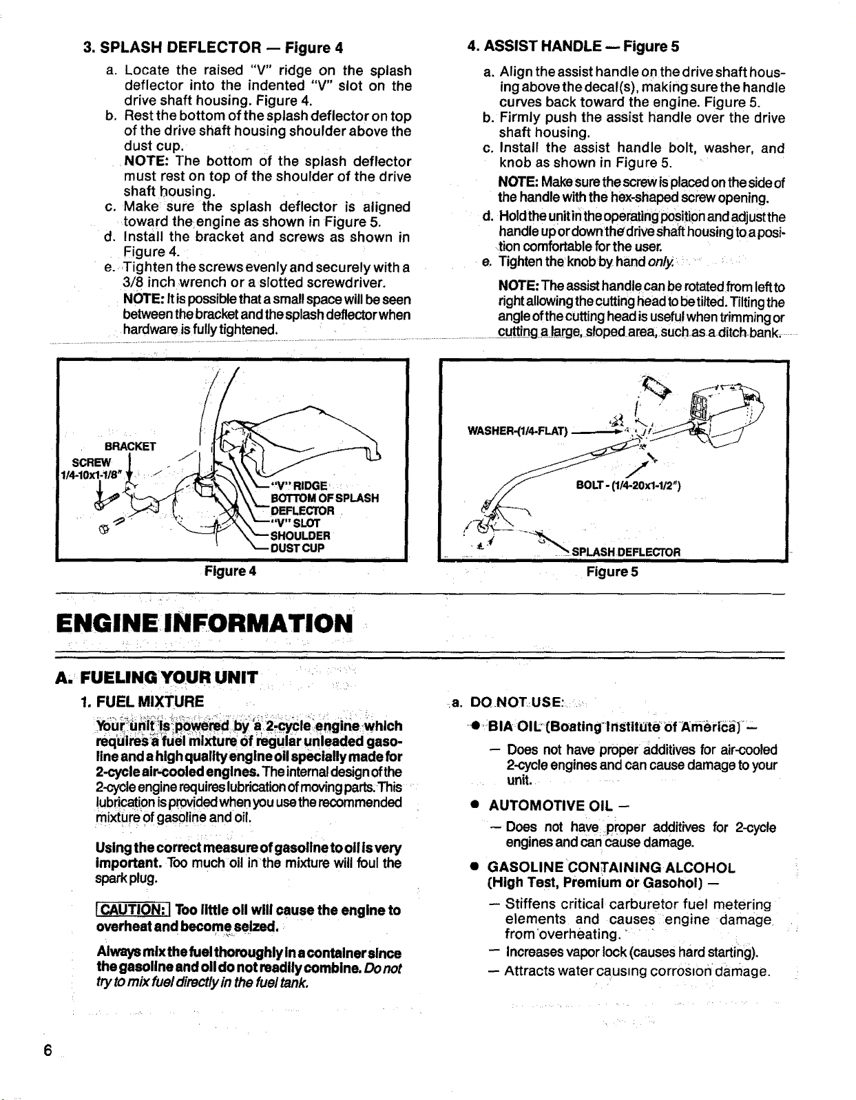
3. SPLASH DEFLECTOR -- Figure 4
a. Locate the raised "V" ridge on the splash
deflector into the indented "V" slot on the
drive shaft housing. Figure 4.
b. Rest the bottom of the splash deflector on top
of the drive shaft housing shoulder above the
dust cup.
NOTE: The bottom of the splash deflector
must rest on top of the shoulder of the drive
shaft housing.
c. Make sure the splash deflector is aligned
toward the:engine as shown in Figure 5.
d. Install the bracket and screws as shown in
Figure 4.
e. _Tighten the screws evenly and secu rely with a
3/8 inch wrench or a slotted screwdriver.
NOTE: It ispossible that a smallspacewill beseen
between the bracket and the splashdeflector when
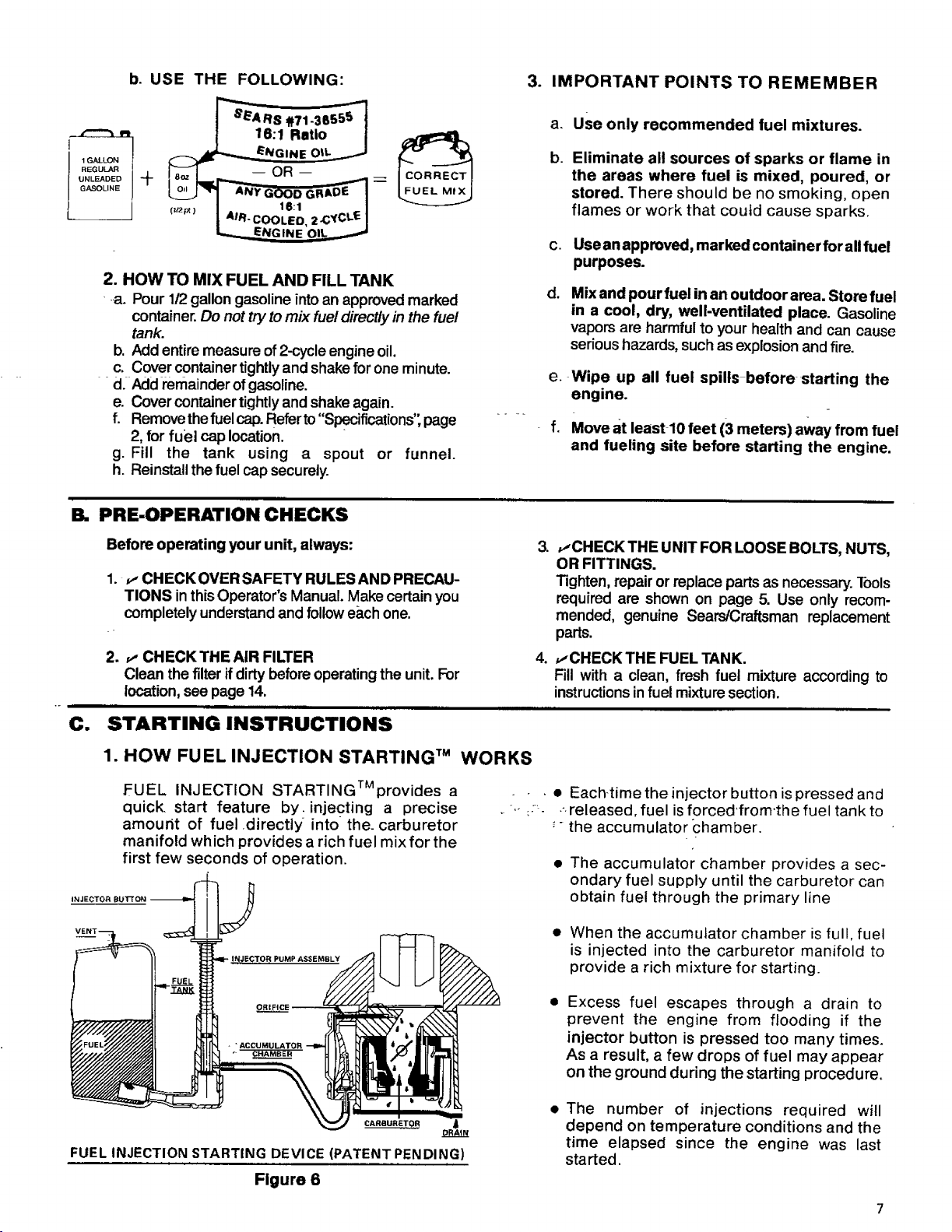
4. ASSIST HANDLE -- Figure 5
a. Align the assist handle onthe drive shaft hous-
ing above the decal(s), making surethe handle
curves back toward the engine. Figure 5.
b. Firmly push the assist handle over the drive
shaft housing.
c. Install the assist handle bolt, washer, and
knob as shown in Figure 5.
NOTE: Makesurethescrewisplacedonthe sideof
the handle withthe hex-shapedscrewopening,
d. Holdthe unitinthe operatingPositionand adjustthe
handleupor downthe'driveShafthousingtoa posi-
,tion comfortableforthe user.
e, Tightentheknobby handonly,+.;+. .....
NOTE: The assist handle canbe rotated from leftto
rightallowingthecuttinghead tobe tilted.Tilting the
angle ofthecuttinghead is usefulwhentrimmingor
iii iiiiililli ¸
I14-10X1-I18" ,++ :-_ " +
.... • • iiiiiiiiii ii i ii iiii
l R=O
+ '_.__._.S_,.-,,"---v SLOT
-. s.ouLoE.
ii iiii
..... DUST CUP ,, ......
Figure 4
ENGINEINFORMATION
A,: FUELINGYOUR UNIT ...._:_ _ :+
1. FUEL MIXTURE
require_;:_ifuel mixture Ofregularunleaded gaso-
lineand ahigh qualltyengine oil specially made for
2-cycleair-cooled engines. The internaldesignofthe
2-cycleenginerequireslubricationofmoving parts,This.....
!ubric=i0 nisp[0videdwhenyouusethe recommended
mixture of gasol ineand oil.
Using the correct measure of gasoitne to oll isvery
important. Too much oit in'the mixture will foul the
sparkplug.
ICAUTION: I Too little oll will cause the engine to
overheat and become seized. _
Always mix the fuel thoroughly in acontainer since
the gasoline and oil do not readily combine. Donot
tryto mix fueldirectlyinthe fuel tank.
' + i '' .... ;: "
, . _ . :
"""I=IIHIIII I + ""111 I L
WASHER-(1/4-FLAT)
BOLT -(1/4-20x1-1/2")
_ SPLASH DEFLECTOR
III
Figure 5
a. DONOTUSE:_ _..._'
.
•,e•BIAOIi.:[Boating-lnStitUte _of+Amei+ic_)+
- Does not have proper additives for air-cooled
2-cycleengines and can causedamage to your
• unit. ..............
• AUTOMOTIVE OIL --
--Does not haveproper additives for 2-cycle
. .' ;
engines and can cause damage.
• GASOLINE CON;rAINING ALCOHOL
(High Test, Premium or Gasohol) --
-- Stiffens critical carburetor fuel metering
elements and causes engine damage
from _overheating. +'
-- Increasesvapor lock(causes hardstarting).
-- Attracts watercausmg corros=on_damage
6
Page 7
b. USE THE
FOLLOWING:
3. IMPORTANT POINTS TO REMEMBER
M
1GALLON
REGULAR
UNLEADED
GASOLINE
+ --OR-- =
2. HOW TO MIX FUEL AND FILL TANK
-a. Pour 112gallongasoline into an approved marked
container.Do not try tomix fueldirectly in the fuel
tank.
b. Add entiremeasure of2-cycleengine oil.
c. Cover containertightlyand shake forone minute.
d. Add remainder ofgasoline.
e. Cover containertightlyand shake again.
f. Remove thefuel cap. Referto "Specifications", page
2, for fuel cap location.
g. Fill the tank using a spout or funnel.
h. Reinstall the fuel cap securely.
B. PRE-OPERATION CHECKS
Before operating your unit, always:
1. v, CHECK OVER SAFETY RULESAND PRECAU-
TIONS inthisOperator's Manual. Make certain you
completely understandand follow e&chone.
2. _, CHECK THE AtR FILTER
Clean the filter ifdirty beforeoperating the unit.For
location, seepage 14.
a. Use only recommended fuel mixtures.
b.
Eliminate all sources of sparks or flame in
the areas where fuel is mixed, poured, or
stored. There should be no smoking, open
flames or work that could cause sparks.
C.
Use anapproved, marked container for all fuel
purposes.
d,
Mix and pour fuel in an outdoor area. Store fuel
in a cool, dry, well-ventilated place. Gasoline
vaporsare harmful to your health and can cause
serioushazards,such as explosionandfire.
e,
Wipe up all fuel spills before starting the
engine.
f.
Move at least 10 feet (3 meters) away from fuel
and fueling site before starting the engine.
,
v-CHECK THE UNIT FOR LOOSE BOLTS, NUTS,
OR FITTINGS.
Tighten, repairor replace parts as necessary.Tools
required are shown on page 5. Use only recom-
mended, genuine Sears/Craftsman replacement
parts.
4
_-CHECK THE FUEL TANK.
Fill with a clean, fresh fuel mixture according to
instructionsinfuel mixturesection.
C. STARTING INSTRUCTIONS
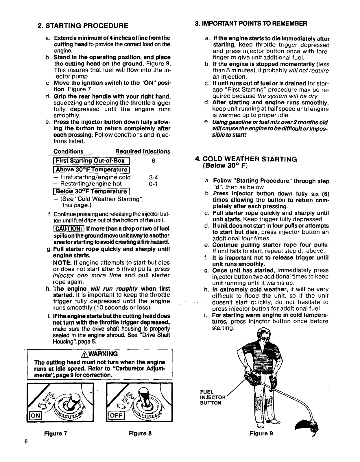
1. HOW FUEL INJECTION STARTING TM WORKS
FUEL INJECTION STARTINGTMprovides a
quick, start feature by. injecting a precise
amount of fuel .directly into the. carburetor
manifold which provides a rich fuel mix for the
first few seconds of operation.
INJECTOR BuI-r ON
CARBURETOR
FUEL INJECTIONSTARTING DEVICE (PATENT PENDING)
Figure 6
DRAIN
- . • Each-time the injector button is pressed and
-.+.:_- ---released, fuel is forced'from'the fuel tank to
'- the accumulator c:hamber.
• The accumulator chamber provides a sec-
ondary fuel supply until the carburetor can
obtain fuel through the primary line
• When the accumulator chamber isfull, fuel
is injected into the carburetor manifold to
provide a rich mixture for starting.
Excess fuel escapes through a drain to
prevent the engine from flooding if the
injector button is pressed too many times.
As a result, a few drops of fuel may appear
on the ground during the starting procedure.
The number of injections required will
depend on temperature conditions and the
time elapsed since the engine was last
started.
Page 8
2. STARTING PROCEDURE
3. IMPORTANT POINTS TO REMEMBER
a. Extenda minimumof4inchesoflinefromthe
cutting head to providethe correctload on the
engine.
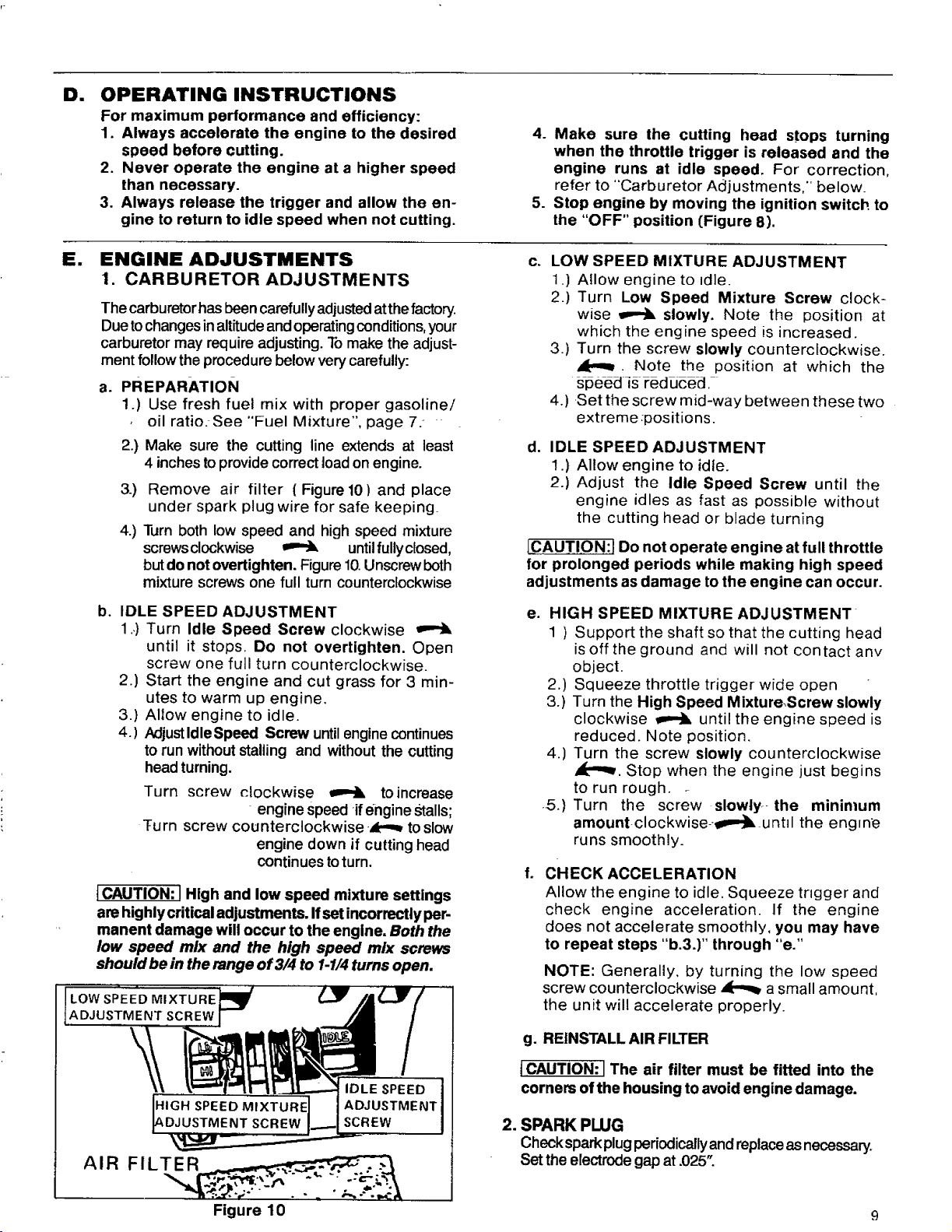
b. Stand in the operating position, and place
the cutting head on the ground. Figure 9.
This insures that fuel will flow into the in-
jector pump.
c. Move the ignition switch to the "ON" posi-
tion. Figure 7.
d. Grip the rear handle with your right hand,
squeezing and keeping the throttle trigger
fully depressed until the engine runs
smoothly.
e. Press the injector button down fully allow-
ing the button to return completely after
each pressing. Follow conditions and injec-
tions listed.
Conditions
I First Starting Out-of-Box [ -
[ Above 30°F Temperature_
-- First starting/engine cold
-- Restarting/engine hot
{Below 30°F Temperature ]
-- (See "Cold Weather Starting",
this page.)
f. Continue pressing and releasing the injector but-
ton untilfuel drips out of the bottom of the unit.
[CAUTION: ] If more than a drop ortwo of fuel
spills onthe ground moveunit away toanother
area for starting to avoid creating a fire hazard.
g. Pull starter rope quickly and sharply until
engine starts.
NOTE: If engine attempts to start but dies
or does not start after 5 (five) pulls, press
injector one more time and pull starter
rope again.
h. The engine will run roughly when first
started. It is important to keep the throttle
trigger fully depressed until the engine
runs smoothly (10 seconds or less)
i. If theengine starts but the cutting head does
not tum with the throttle trigger depressed,
make sure the drive shaft housing is properly
seated in the engine shroud. See "Ddve Shaft
Housing",page 5.
Required Injections
6
3-4
0-1
a. If the engine starts to die immediately after
starting, keep throttle trigger depressed
and press injector button once with fore-
finger to give unit additional fuel.
b. If the engine is stopped momentarily (less
than 5 minutes), it probably will not require
an injection.
c. If unit runs out of fuel or is drained for stor-
age "First Starting" procedure may be re-
quired because the system will be dry.
d. After starting and engine runs smoothly,
keep unit running at half speed until engine
is warmed up to proper idle.
e Usinggasoline orfuelmix over2 months old
will cause the engine to bedifficult or impos-
sible to start!
4. COLD WEATHER STARTING
(Below 30 ° F)
a. Follow "Starting Procedure" through step
"d", then as below.
b. Press injector button down fully six (6}
times allowing the button to return com-
pletely after each pressing.
c. Pull starter rope quickly and sharply until
unit starts. Keep trigger fully depressed.
d. If unit does not start in four pulls or attempts
to start but dies, press injector button an
additional four times.
e. Continue pulling starter rope four pulls.
If unit fails to start, repeat step d., above.
f. It is important not to release trigger until
unit runs smoothly.
g. Once unit has started, immediately press
injector button two additional times to keep
unit running until it warms up.
h. in extremely cold weather, it will be very
difficult to flood the unit, so if the unit
doesn't start-quickly, do not hesitate to
press injector button for additional fuel.
i. For starting warm engine in cold tempera-
tures, press injector button once before
starting.
/_WARNING
The cutting head must not turn when the engine
runs at idle speed. Refer to "Carburetor Adjust-
merits", page 9 for correction.
FuEL
INJECTOR
BUTTON
Figure 7 Figure 8 Figure 9
Page 9
D=
OPERATING INSTRUCTIONS
For maximum performance and efficiency:
1. Always accelerate the engine to the desired
speed before cutting.
2, Never operate the engine at a higher speed
than necessary.
3. Always release the trigger and allow the en-
gine to return to idle speed when not cutting.
Sm
ENGINE ADJUSTMENTS
1. CARBURETOR ADJUSTMENTS
The carburetorhasbeen carefully adjusted atthe factory.
Dueto changesin altitude and operating conditions, your
carburetor may require adjusting. To make the adjust-
ment follow the procedure below very carefully:
a. PREPARATION
1.) Use fresh fuel mix with proper gasoline/
oil ratio. See "Fuel Mixture", page 7.
2.)
Make sure the cutting line extends at least
4 inches toprovide correct load on engine.
3.)
Remove air filter ( Figure 10) and place
under spark plug wire for safe keeping_
4.)
Turn both tow speed and high speed mixture
screws clockwise _ untilfullyclosed,
but do not overtighten. Figure 10.Unscrew beth
mixture screws one full turn counterclockwise
b.
IDLE SPEED ADJUSTMENT
1 .,)Turn Idle Speed Screw clockwise
until it stops. Do not overtighten. Open
screw one full turn counterclockwise.
2.) Start the engine and cut grass for 3 min-
utes to warm up engine.
3.) Allow engine to idle.
4. ) AdjustIdleSpeed Screw untilengine continues
to run withoutstalling and without the cutting
head turning.
Turn screw clockwise _ to increase
Turn screw counterclockwise -_k'.,_to slow
l CAUTION: JHigh and low speed mixture settings
are highly critical adjustments. If setincorrectly per-
manent damage will occur to the engine, Both the
low speed mix and the high speed mix screws
should be in the range of 3/4 to 1-1/4turns open.
- engine speed if engine Stalls;
engine down if cutting head
continues toturn.
4. Make sure the cutting head stops turning
when the throttle trigger is released and the
engine runs at idle speed, For correction,
refer to "Carburetor Adjustments," below_
5. Stop engine by moving the ignition switch to
the "OFF" position (Figure 8).
C. LOW SPEED MIXTURE ADJUSTMENT
1.) Allow engine to =die.
2.) Turn Low Speed Mixture Screw clock-
wise _ slowly. Note the position at
which the engine speed is increased.
3.) Turn the screw slowly countercfockwise.
JP.,_. Note the position at which the
speed is reduced.
4.) Set the screw mid-way between these two
extreme :positions.
d. IDLE SPEED ADJUSTMENT
1.) Allow engine to idle.
2.) Adjust the Idle Speed Screw until the
engine idles as fast as possible without
the cutting head or blade turning
E-CAUTION:] Do not operate engine at full throttle
for prolonged periods while making high speed
adjustments as damage to the engine can occur.
e. HIGH SPEED MIXTURE ADJUSTMENT
1 ) Support the shaft so that the cutting head
is off the ground and will not contact anv
object.
2.) Squeeze throttle trigger wide open
3.) Turn the High Speed MixtureScrew slowly
clockwise _ until the engine speed is
reduced. Note position.
4.) Turn the screw slowly counterclockwise
_'"_. Stop when the engine just begins
to run rough.
,.5.) Turn the screw slowly.-the minimum
amount-clockwise--_p--']l= until the engvne
runs smoothly.
f.
CHECK ACCELERATION
Allow the engine to idle. Squeeze trigger and
check engine acceleration. If the engine
does not accelerate smoothly, you may have
to repeat steps "b.3.)" through "e."
NOTE: Generally, by turning the low speed
screw counterclockwise _ a small amount,
the unit will accelerate properly.
g. REINSTALL AIR FILTER
tCAUTION: I The air filter must be fitted into the
corners of the housing to avoid engine damage.
2. SPARK PLUG
Check sparkplugperiodically and replaceasnecessary.
Set the electrodegap at .025".
Figure 10 9
Page 10

USING YOUR UNIT
Your Trimmer is equipped with a semi-automatic advancing
cutting head that cuts with the tipof amonofilament nylon line.
The nylon cutting line will easily remove grass and
weeds from around walls, fences, trees, and flower
beds, but it also can cut the tender bark of trees or
shrubs and scar fences. For this reason, it is very
important to learn the proper techniques of cutting
around and near objects.
The nylon cutting line will wear faster and will
require being advanced more frequently when you
are cuttingagainst rocks, bricks,concrete, metalfences,
etc., than against trees or wooden fences.
The cuttinghead will wear prematurely:
--if allowed to continuously contact the ground
during normal cutting.
--if the line limiter is not kept sharp.
WARNING
Use only flexible, non-metalic, monofllament cutting
line. Do not use other materials such as rope, wire, etc.
Wire can break off during cutting and become a
dangerous missile.
A. OPERATING INSTRUCTIONS
1. Read your Operator's Manual.
Make certain you completely understand and follow
all safety rules, precautions, and operating instruc-
tions before operating the unit.
,
and face which can result in loss of vision or
serious personal injury.
3.
Dress safely in long pants-and wear boots or
safety shoes.
Do not wear Iooseclothing, jewelry, short pants or
sandals; or go barefoot.
4. Check the unit before operation.
Lookforworn,loose, missing,ordamaged parts.Donot
useuntilthe unit isinproperworkingorder.
,
Inspect the area to be cut.
Remove all debris and objects that can ricochet, be
thrown,becomeentangledinthe cuttingheadorother-
wisecause injuryor damage duringcutting.
6.
Keep observers, children, bystanders, and animals
safely away.
Beforestartingthe engineandduringoperation,make
certainchildren,animalsandbystandersare awayfrom
the workarea - a minimumof 30 feet(10meters).
Always wear eye protection. The
splash deflector/line limiter will not
prevent rocksand debris frombeing
thrown or ricocheting into the eyes
B. ADVANCING THE CUTTING LINE
• The cutting line is extended semi-automatically by
tapping thebottom ofthe head on the ground with
.the engine_running.
k.• Approximately 2 Inches oflinelsextended each
time the tap button istapped on the ground,
• The line,miter on the splash deflector cuts line to
a maximum allowable length.
• The most efficient cutting line length Is the max-
imum length allowed by the line Iimiter.
1. To advance line:
a. Operate the engine at fullthrottle.
b. Hold cutting head parallel to and above the
grassy area ofthe ground.
c. Tap the cutting head lightlyonthe ground one
time. See Figure 12. Approximately2 inches of
line will be advanced after each tap.
NOTE: Ifthe line isworn down totwo inches or
less, more than one tap may be required to
obtain the most efficient line cutting length.
10
2. Always keep the splash deflector in place when
the unit Is being operated.
-3. Keep the line Iimitersharpfor fast, easycut-off.
See page 13for sharpening instructions.
NOTE: Always tap the cutting head ona grassy
area of the ground. Tapping on surfaces such
as concrete or asphalt can cause excessive
wear to the cutting head.
LINE CUTTING LINE,
LIMITER TAP LIGHTLY
CUTSEXCESS ON GROUND
LINE ONE TIME
TO ADVANCE
-q
Page 11

C. CUTTING METHODS
• The tip of the line does the cutting. Allow the unit
to trim at its ownpace. YouwilJachieve better results
bynot crowding the line into the cutting area. The right
way and wrong way are shown in Figure 13.
• Always cut left to right,
ii
'- \
RIGHT
, I
_WRONG
iii i
Figure 13
_WARNING
Always wear eye protection. Never lean over the
cutting head. Rocks or debris can ricochet or be
thrown into eyes and face and cause loss of
vision or serious personal injury.
J p
\',,
TRIMMING
i i
Figure 14
.
TRIMMING -- Figure 14
Hold the cutting head at a 30 degree angle to the
cutting area for efficient trimming. Do not forcethe
cutting line intothe workarea. Allowt.hetipofthe line
todo the cutting.
2, EDGING -- Figure 15
Adjustyourtrimmer foredging byturningtheengine
upside down so the drive shaft housing angles out
rather than down. Rotate the assist handle on the
shaft, placing it in an up, usable position. Hold the
cutting head above the area to be edged as shown
and operate thethrottle trigger with your thumb,
3. MOWING -- Figure 16
Yourtrimmeris idealfor mowing inplaces conventional
fawnmowers cannot reach.Inthe mowingposition,the
cuttinglineisparalleltotheground.Avoidlettingthecut-
tinghead continuously contact the groundas this can
causedamage toyourunitaswell asscalpthe ground.
4. SCALPING -- Figure 17
Toremove unwanted vegetation around trees, posts,
monuments, etc., maintain a 30degree angle with the
cutting head and allow the tip of thecutting line to
strike the ground.
NOTE: Increased line wear is to be expected when
using scalping techniques.
,
SWEEPING -- Figure 18
Forquick and easy clean up extend the line to the
length allowed bythe line limiter and move the unit
from sidetoside, keeping the cutting headparallelto
the surfaces being swept•
Figure 15
Figure 16
Figure 18
11
Page 12

D. CUTTING HEAD MAINTENANCE
1. CUTTING LINE REPLACEMENT
a. Hold the cutting head as shown in Figure 18.
Press the lock tab, and turn lock ringcounter-
clockwise
b. Remove the lock ring, tap button, and
spool. Figure 19.
c. Clean dirt and debris from housing and
spool.
d. Inspect spool. Replace as necessary. See
instruction #3 this section.
i i i i i i
PressLock Tab.
Turn outer ring
counterclockwise,
\l
l
LOCK TAB
Figure 18
,=,,i ii ii
NOTE: The aluminum line saver is reversi-
ble. After a groove is worn into one side,
reverse the line saver (with the spool
removed) to provide a new wear surface.
Figure 21.
e°
Replace a worn spool with a new pre-wound
spoolfor quickeasy replacement.Or asan alter-
native, replace nylon line on existing, usable
spool.Toreplaceline,insert1/16to1/8 inchofthe
endofthe linethroughtheholeinthe spool.Wrap
the line evenly onto the spool in a clockwise
directionasshownby arrowonspool.
Figure20.
f. Insertthe endofthe linethrough the line saver as
showninFigure21.Pushspoolin housing.Force
spooldown. Turnandlockspoolunderthe drive
lugsonthe drive gear.
g. Replace the tal_button; press lock tab and
install the lock ring. Turn the lock ring
clockwise _ and fasten under the
catches on the housing. Figure 22. Check
to be certain all catches are properly se-
cured.
TAP BUTTON
Figure 19
U$1NG
Figure 21
! I I I[11 II I
Turn Lock Ring
clockwise to install,
\
12 Figure 20 Figure 22
Page 13

h.
Pull on the nylon line to change the spool from the
lockedposition tothe operating position. Figure 24.
in
Obtain correct line length bypressing tap button and
pulling on nylon line again.
NOTE: Approximately 2 inches of line can be
advanced each time the tap button is pressed.
Figure 24.
USE ONLY SEARS/CRAFTSMAN ®
REPLACEMENT PARTS
2. CUTTING LINE REPAIR
•If the cutting line breaks off or backs up in the
cutting head, follow "Cutting Line Replacement",
omittingstep "e".
3. SPOOL REPLACEMENT
Approximately2 inches
of linecanbeadvanced
eachtime the Tap Button
is pressed.
TAP BUTTON
Figure 24
a Replace the spool when: The square corners of
the drive lugs are rounded off, reduced in size, or
broken off. Figure25.
b. To replace the spool, follow "Cutting Line
Replacement" (page 12).
4. LINE LIMITER MAINTENANCE
• The line limiter is the metal blade found on the
splash deflector.
_-Theline-limiter must be kept sharp to:
-- allow fast, easy cut-off.
avoid excessive wear to the cutting head.
•• Tosharpen:
Use a fiat file and file from the outside towardthe
insideofthe line limiter,Figure 26.
NOTES
NORMAL SPOOL
WORN SPOOL
i ii
Figure 25
Figure 26
13
Page 14

GENERAL MAINTENANCE
A. DRIVE SHAFT LUBRICATION
• Lubricate the Flexible Drive Shaft:
-- After each ten (10) hours of operation:
-- Before operating if the unit has been stored
for 90 days or longer.
• Use gear grease stock #28-59071.
NOTE: Atube ofgrease has been suppliedwithyour
unit tobe used after the first 10 hoursofoperation.
NOTE: Check the Flexibie Drive Shaft for
wear or damage, Replace if broken wires,
twists or kinks are found.
ICAUTION:tLay the Flexible Drive Shaft on a
clean surface. Avoid laying the shaft on the
floor, ground or on any surface that may have
dirt or debris. Even after wiping the shaft,
grease residue can pick up dirt particles that
can cause damage or premature failure.
• Observe the following procedure for best
results:
CAUTION: IAvoid bodily contact with the muffler
area when the engine is warm. Always replace
the muffler guard if it becomes damaged or
broken.
1. Loosen the Pinch Clamp Bolt and remove the
Drive Shaft Housing from the Engine Shroud.
2. Remove the Flexible Drive Shaft as shown in
Figure 26.
3. Using a clean cloth, thoroughly wipe the sur-
face of the Flexible Drive Shaft to remove any
old grease that may be present/
4. Applya uniformcoatofgear greasetothe entire sur-
face ofthe Flexible Drive Shaft. Figure 27.
5. Inject the remaining contents of the tube sup-
plied with the unit into the top of the Drive
Shaft Housing.
6. Replace Flexible Drive Shaft in the Drive
Shaft Housing.
7. Follow the instructions on page 6 to replace
Drive Shaft Housing in the Engine Shroud.
Wipethe Flexible
14
Figure 26
El
AIR FILTER CARE
A dirty air filter decreases engine performance
and increases fuel consumption,
Clean the Air Filter:
• Frequently,
• Always after 5 tanks of fuel or 5 hours of opera-
tion, whichever is less,
Follow these steps:
1, Removetheairfilter(Iocatedatthebettom, rearofthe
Engine Shroud)see page 2.
2, Wash in soap and water.
ICAUTION:] Do not clean filter in gasoline
or other flammable solvent to avoid creating
a fire hazard.
3. Squeeze filter dry.
4, Replace the air filter.
ICAUTION: fThe air filter must be fitted into
the corners of the housing to avoid engine
damage.
iiii ]1 iii
Figure 27
Cll
FUEL TANK UPKEEP
Never use gasoline that ismore than 2 months
old in a fuel mixture. Gasoline begins to break
down after a period of time and will form com-
pounds that cause hard starting and damage in
2-cycle engines.
,
inspect the unit for fuel leaks each time it is
used. Repair or replace parts as necessary.
2.
Using gasoline or fuel mix over 2 months old will
cause the engine to be difficult or impossible to
startl
.
Drain the fuel tank or allow the unit to run out
of fuel before storing for 30 or more days.
NOTE: "First Starting" procedure may be
required fora unit that runs out of fuel or from
which fuel is drained, See "Starting Instruc-
tions", page 8.
Page 15

D. STARTER ROPE REPAIR
• Repair the starter rope If the rope breaks next
to the pulley.
• Replace the starter rope if the rope breaks 2-3
inches away from the pulley as the rope will be
too short to repair properly.
/_WARNING
Always wear eye protection when ser-
vicing the starter rope. The recoil spring,
located beneath the pulley, is under ten-
sion. Ifthe spring pops out, serious per-
sonal injury can result.
• To repair or replace:
NOT_ Use caution when separating the
fan housing from the shroud to avoid
breaking or damaging the fuel line fittings.
1_ Drain all fuel from tank.
2. Remove the four (4) screws from fan
housing. Figure 28.
3. Carefully separate fan housing from shroud-
about one (1) inch.
4. Disconnect fuel lines from fittings.
5. Disconnect ignition module wires. Figure
28.
6. Slide high tension lead grommet from slot,
in fan housing.
7. Separate the fan housing completely from
the shroud.
8. If the starter rope is not broken, release
the spring tension by pulling about 12
inches of rope from the pulley and catch
the rope in the notch as shown. Figure 30.
NOTE: The tension on thestarter spring
will be released if the rope has broken.
9. Remove screw and pulley very carefully.
Figure 29. The recoil spring which lies
beneath the pulley must stay in the hous-
Ing, flat against t6e bottom. Itthe spring Is
disturbed, it will require oonsiderable time
and effort to reinstall. Twist the pulley
gently clockwise ,,,,-]& ' as you pull up to
release the spring.
10. Moveawayfromthefuel tankand melttheend0f
the newrope togo intothe pulley,
11. Allowthe meltedendtoddponce, thenwhilerope
isstillhotpullthe meltedend througha cleanrag
toobtain a smooth, pointedend.
12. Insert rope through the rope exit hole in
the fan housing.
13. Guide rope insidepulley,thenupthroughtopside
pulley holebypushing the rope fromthe under-
side hole with a small object such as a
screwdriver.
14. Wrap rope counterclockwise 4[--,, around
pulley ratchet and tuck loose end back
under-rope leaving a 1/4 to I/2 inch
tail laying in the rope groove. Figure 30.
15. Wind all but about 12 inches of the rope
counterclockwise _ around pulley.
16. Replace pulley in the housing. Be sure
the pulley is all the way down and the
spring is secured. Replace screw and
tighten. Figure 29.
17. Hold the 12 inch slack in the rope and
catch rope in pulley notch. Figure 30.
18. Hold the rope taut and make 2 complete
turns of the pulley counterclockwise
to place tension on the pulley.
Hold the pulley to retain tension.
19. Align pulley notc_ with rope exit hole,
pull starter handl_tothe full extent of the
rope and allow the rope to slowly wind
around the pulley.
NOTE: While the unit is disassembled, in-
spect the carburetor housing seal and
replace if worn. Figure 28.
20. Reverse procedure for re-assembly of fan
housing to shroud.
NOTE: Make sure the fuel line with the
black stripe or solid color is installed on
i.i i i
GROMMET
SHROU[
CARBURETOR
HOUSING
FUEL LINE FITTINGS
IIGNITION MODULE WIRES
LINES
i ii
Figure 28
,o., ,o.,
NOTCH
Figure 29
Figure 30
FAN
3USING
15
Page 16

TROUBLE SHOOTING CHART
TROUBLE CAUSE
Engine will not start 1. Ignitionswitch off.
2. Fuel tank empty,
3, Spark plug not firing.
4. Fuel not reaching carburetor,
5. Engine flooded.
6. Compression low.
Engine will not idle
1. Idlingspeed set toolow.
properly
2. idle speed set too high.
3. Low speed screw requiresadjustment.
I 4. Crankshaftseals worn.
5 Compression low.
Engine will not - 1.
accelerate, lacks 2.
power or dies 3.
under a load 4.
Carburetorrequires adjustment.
Air filter dirty.
Spark plugfouled.
Carbonbuild-up.
5. Lowcompression.
Engine smokes
excessively
1. Highspeed needle requiresadjustment. 1.
2. Air filter dirty. 2.
3. Oil richfuel mixture. 3`
Engine runs hot 1.
! Unit engages at 1.
idle speed 2,
Cutting head dobs not 1.
tum when engine is 2.
accelerated 3.
Cutting head stops
:under e load
Cutting line does
not advance.
Fuel Mixture Incorrect.
2.
Spark Plug Incorrect.
3.
Carbon build-up.
4.
High Speed Mixture set too low.
Carburetorrequires adjustment.
Clutch requiresrepair.
Driveshaft notengaged.
Carburetorre_:luiresadjustment.
Clutch slipping.
1.
Drive shaftnotengaged.
2.
Carburetorrequires adjustment.
&
Clutch slipping.
Line improperlywound'ontospool,
1.
2.
Drive.gear damaged orworn.
3.
Worn spool.
REMEDY
1. Move switch'to"Start", ....
2. Filltank withcorrectfuel mixture.
3` Installnewplug.
4. Check for dirtyfuelfilter; ctean.Check
forkinkedorsplit fuelline; repairor
replace.
5. See Starting Instructions.
6. Contact your SearsService Center.
,,,,,........
1. Adjust idle speed screw clockwise to
increase speed.
2. Adjust idle speed screw counter-
clockwiseto reduce speed.
3. See Carburetor Adjustments.
4. Contact your Sears Service Center.
5. Contact your Sears Service Center.
1. See Carburetor Adjustments.
2. Clean or replace air filter,
3. Clean or replace Spark Plug and regap.
4. Clean exhaust system includingspark
arrestor.
5. Contactyour SearsService center.
See Carburetor Adjustments.
Clean or replaceair filter.
Emptyfuel tankand refillwithcorrect
fuel mixture.
.
See FuelingYour Llnit.
2.
Replace with correct plug.
3.
Clean exhaustsystemincludingspark
arrestor.
4.
See CarburetorAdjustments.
1.
See Carburetor Adjustments.
2.
Contactyour Sears Service Center.
1.
See AssemblyInstructions.
2.
See Carburetor Adjustments.
3.
Contact your Sears Service Center.
1.
See Assembly Instructions.
.2,
See CarburetorAdjustments....
Contact .yourSears Se,rviceCenter.
1.
Rewindspool.
2,
Replace drive gear.
&
Replace spool.
16
Page 17

ACCESSORIES
A. ACCESSORIES
2-Cycle Engine Oil ............................................ Stock No.
Gear Grease (14-112oz.) ........................................ Stock No.
Spark Plug ................................................... Part No.
Replacement Cutting Head ..................................... Stock No.
Spool W/Line ................................................ Stock No.
Nylon Cutting Line ............................................ Stock No.
Shoulder Strap Kit ............................................ Stock No.
NOTES
71-36555
28-59071
STD361258
71-85764
71-85789
71-85778
71-85783
17
Page 18

SEARS WEEDWACKER ® PARTS LIST -- MODEL 358.796131 -26.2cc
Figure 1
25
101
26
28
27
29
30
f
I
31
18
19
2O
14
10
Page 19

SEARS WEEDWACKER ® PARTS LIST m MODEL 358.796131-26.2cc
Figure I
KEY
NO.
1
2 93896 1
3 93898 1
4 92067 1
5 92068 1
6 93897 1
7 706502 1
8....... 9338? ..... 1
9 92133 1
10 92243 2
11
12
14
15
19
2O
KeyNo's Excluded:#13,1618, 21.24.
PART
NO.
706515
"93653 1
93716 1
94440 1
15337 2
93853 1
STD 2
540410
QTY.
RECL
DESCRIPTION
1
Cutting Head Assembley
Stock#71-85764 (Incl. 2-9)
Hub wlLine Saver
Line Saver
Spring
Adaptor- Spring
Drive Gear
Spool w/Une-Stock #71-85789
....ReleaseButton_
COVer
Screw-l/4-10xl-l/8-Splash
Deflector
Bracket- Splash Deflector
DustCup
Splash Deflector
Screw- 10-24xl - Line Limiter
LineLimiter
Nut- 10 -24 - Locking
KEY
NO.
25
26
27
28
29
3O
_3_1_
32
Decals
-101
102
103
104
PAR'I:
NO.
10618
92059
STD
551025
STD
522517
94439
93936
3_0_1_02
66706
26593
27153
26674
26570
REQ.
1
1
I
1
1
i
1
1
1
DESCRIPTION
Assist Handle
Knob- 1/4- 20
Washer- 1/4- Flat
Hex Bolt-114-20x1-112
DriveShaft Housing
Rexible Drive Shaft
.....GeajG re_e_Sto__k#28-590"£1....
Operator's Manual
Warning Label -AssistHandle
Decal -Warning (Shaft)
Decal -Weedwacker
Decal -Splash Deflector
19
Page 20

SEARS WEEDWACKER ® PARTS LIST -- MODEL 358.796131-26.2cc
Figure 2
21
I
I
t
I
I
I
J
24
36
6 ] 11
!
!
(
43
20
-35
Page 21

SEARS WEEDWACKER ® PARTS LIST -- MODEL 358.796131-26.2cc
Figure 2
1
PART QTY.
NO. REQ,
24436 i: 1
26566 1
26567 1
KEY
NO.
2
3
24365 1
5 24371
6 23575
7 STD
6108O7
8 69182
9 15706
10 24569
11 15582
12 24461
13 15367
14 26109
15 21052
16 10729
18 22290
19 21053
20 26931
21. 69178
22 _ 42067
- 23 26035
24 15544*
25 26048
DESCRIPTION
Bumper Fuel Tank Housing
Handle & Fuel Tank Housing
KEY
NO.
26
27
Handle Cover
_igger- Throttle
1
Air Filter
1
Nut- Grounding Switch
1
Screw - 8 - 16 x3/4 Pan Head-
Handle Cover
K'rt-Grounding Switch
(Inc1.#6,10&39, this page
28
29
30
31
32
33
and #12from page 23)
Screw- 10- 24 x 1- 1/2- Sems
Fan Housing - Top
1
Washer- Ground Terminal
2
Screw- 10- 24 x 5/8- Seres
Fan Housing - Bottom
1
Trigger- Spring
5
Screw- 10-14 x 3/4- Fan
Housing to Handle & Fuel
Tank
1
Rlter- Fuel (InletLine)
1
Une- Fuel Inlet
1
FuelCap.Assembly
(Incl. O-Ring)
1
Rope (3.5ft)
1
Line- Pump toAccumulator
1
FuelPick-Up Assembly
1
Fan HousingI_t
1
Starter Recoil Spdng
1
AirBaffle
2
Screw- 1/10x 3/8 Pan Hd.-
34
35
36
37
38
39
4O
41
42
43
Decals
101
PART QTY.
NO. REQ.
15123
15479
26O32
10738
16563*
= -=
26119
21054
26178
26549
10773
15590
15669
26560
39122
15610
26792
STD
511010
15274
27153
26568
26569
DESCRIPTION
1
1
Washer#10StarterPulleyScrew
Screw -#10 x 3/4- Hex Washer
Head - Starter Pulley
1
1
1
InjectorButton
Pump Assembly(Inc1.#19)
•screw- #10x 1 - 3/16Plastite
AirBaffleI Pump Mounting
1
1
1
Check Valve- Duck Bill
Fuel Une - Tankto Accumulator
Clip- Retainer- Inlet Line-
FuelTank
1
1
Shroud
FuelTankAssembly(Incl. #14,
15,16,20,31,32&33)
2
1
1
1
1
1
Screw- 10- 2 x 5/8 Binder Head
Screw-Pinch Clamp-1/4-20x9/16
Clamp
Lead Wire - Ground
Nut #12-24Square
Ass'y.- Rope and Handle-
Starter(Incl.#18)
4
Screw- 10- 24 x 718- FiI.Hd.
Shroud
4
Washer- Flat,#10Narrow
Shroud
Decal- Instructions
1
DeCal- Shroud(Right)
-(not shown)
• Decal - Shroud(Left)
_;(notshown)
Air Baffle
Starter Pulley
*If yourunit has beenserviced withthe metal fan housing, use PartNo. 15373(Screw- #10 -24x 1/4- FiL Hd.), instead of15544
(KeyNo.24), and Part No. 15305 (Screw- #10 - 24x 1 - 3/1-6RI. Hd.), instead of15563 (KeyNo30).
Key No'sExcluded:#17
21
Page 22

4
SEARS WEEDWACKER ®PARTS LIST -- MODEL 358.796131-26.2cc
Figure 3
10-
11-
7
51
52
9
7
16
53
54
57
58
35
22
Page 23

SEARS WEEDWACKER ® PARTS LIST- MODEL 358.796131-26.2cc
Figure 3
KEY
NO.
:27
10
11
12
13
14
15
16
17
18
19
2O
21
22
23
24
25
26
26
29
3O
4
6
8
9
1
2
3
5
7
PART
NO.
42059
STD
54I 131
15127
39114
STD
551OO8
69181
19059
15168
1O316
39103
24435
25995
15235
1O677
19128
15565
39082
3934
3933
STD
361258
15126
23373
26177
10651
24302
15162
32058
15351
24438
QTY.
REQ.
2
I
1
1
2
1
2
4
1
1
1
1
2
1
2
1
1
1
1
1
1
1
1
1
2
2
2
1
DESCRIPTION
Spring - Starter Dog
Nut - Flywheel - (5/16x 26)
Washer- Flywheel
Rywheel Assembly (Incl. #1)
Screw - 8-32 x 3/4 - Fil. Hd.-
Ignition Module
Kit - Ignition Module
Seal - Crankcase
Screw - Crankcase
Crankcase Ass'y.(Incl.#7& 28)
High Tension- Lead Assembly
(Incl. #17,18& 19)
Grommet- Plug Wire
ElectricalTab
Screw- 8-18 x 9tl6
Cap Assembly- Accumulator
(Incl. Cap, Screen & "O"
Ring)
O-Ring-Accumulator
Chamber
Screw - 8-18x1'-'Accumulator
High TensionLead Wire
Boot- Spark Plug
Connector- Spark Plug Lead
Spark Plug (CJ-14)
Key- Rywheet
Boot-Throttle
ThrottleWire (Red)
AccumulatorAssembly
(Incl,#14,15 &34)
Gasket -Cylinder
Ring -Piston
Retainer-Wrist Pin .
Beadng- Crankcase
Washer- Thrust -Crankcase
Reed Valve
KEY
NO.
31
32
33
34
35
36
37
38
"39
40
41
42
43
44
45
46
47
48
49
5O
51
52
53
54
55
56
57
58
PART
NO.
19108
19105
21055
19131
26047
STD
610805
STD
610603
23367
15239,.
12070
26949
24903
22198
32057
26675
26O46
19115
35183
15566
24364
24361
24362
69196
69194
24932
24855
10797- -
3O054
QTY.
REQ.
1
1
1
1
4
1
1
2
1
1
2
1
1
1
1
1
1
1
1
1
1
1
2
1
1''
DESCRIPTION
Gasket- Carburetor Case to
Crankcase
Seal -Carburetor Case
Fuel Line- Carburetor
O- Ring (Orifice)
Cover- Carburetor Case
Screw- 8 - 18 x9/16 - Pan
Hd. - CarburetorCase Cover
Screw-6 - 19x 5/15- Pan Hal.-
Reed Valve
:Washer- Reed Valve Screw
,Screw- 114-20 x3/4 - Hex
SocketHd.- Cylinder
Cylinder
Diffuser- Muffler
Spring- Muffler Detachment
PistonKit (Inc1.#26,27& Pin)
Bearing - WristPin
Crankshaft & ROdAssembly
Carburetor Housing
Gasket- Carburetor
Carburetor- WA - 149 -
(See Page 24 for Assembly)
Screw - 10- 24 x 2-1/4"-
Fil. Hd. -Carburetor
Screen - Spark Arresting
Cover- Muffler
Body- Muffler
Kit- ClutchWasher
Kit- ClutchAssembly (Incl.
ClutchWasher)
Spring- Muffler Guard
Guard - Muffler
Coupling &Bearing Assembly
_Sealant- Crankcase
(Not SuppliedWith Unit)
23
Page 24

SEARS WEEDWACKER ® PARTS LIST -- MODEL 358.796131-26.2cc
CARBURETOR NUMBER 35183
Figure 4
KEY PART
NO. NO.
1 35017
2 35191
3 35164
4 35156
5_ 35178
6 35166
7 35133
8 35007
9 35138
10 35015
11 35132
12 35023
13 35141
14 35106
15 35031
16 35o31
Conteht_ of Gasket/Diaphragm Kit
+Contents of Kwik Repair Kit
QTY'. KEY
REQ. DESCRIPTION NO.
1 Screw -"Pump- Cover 17
1 Pump Cover Ass'y. (Incl. #4) 18
1 *+ Gasket- Pump 19
1 . Screw- Idle Adjustment 20
1_ + Screen - Inlet
1 *+ Diaphragm - Pump
1 Valve - Throttle
1 Clip - Throttle Shaft
1 Spring - Throttle Return
1 + Screw - Throttle Valve
1
1
1
1
1
1
Shaft Assembly - Throttle
Spring - Idle Needle
Needle - Idle
+
Spring - Metering Lever
+
Valve - Inlet Needle
+
Lever- Metering
PART QTY
NO, REQ.
35036 1
35142 1
35026 1'
35016 1
21
22
23
24
25
26
27 35149
35147
35042
35137
35151
35014
35153
35185
35186
DESCRIPTION
Spring- Hi Speed Needle
Needle - Hi Speed
+
Pin - Metering Lever
Screw - Metering Lever Pin
-1* *+ Gasket - Circuit Plate
1 •Plate - Circuit
1 + Screw - Circuit Plate
1 *+ Gasket-Metering Diaphragm
1 *+ Diaphragm Ass'y.- Metering
4 Screw Assembly - Metering
Cover & Throttle Shaft Clip
1
1
Cover- Metering Diaphragm
Kit - Kwik Repair Kit
(Not Shown)
Kit - Gasket / Diaphragm
(Not Shown)
Page 25

NOTES
25
Page 26

NOTES
26
Page 27

I I I IIII IIIIII
QUICK REFERENCE PAGE
Read and follow all Safety Rules, Precautions and Operating Instructions.
Failure to do so can cause in serious personal injury.
PAGE
PREPARATION ........................................................................... 3
1.Know all safety rulesand precautions inthismanual.
2. Wear safety glassesorgoggles for eye protection
3. Dress safely- bootsor safetyshoes, long pants.
4. Check for worn, loose, missing or damaged parts and repair.
5. Inspectand ensure the area to be cut issafe.
6. Keep children,bystanders,and animals a minimum of30feet (10 meters)away from the workarea.
FUELING ............................................................................... 6-7
1. Eliminate allsourcesofsparks orflame where fuel ismixed, poured orstored.
2. Use fuel notover2 months old.
3. Mix and pour fuel inan approved, marked container in anoutdoorarea.
4. Use 1 partair-cooled, 2-cycle,engine oil to 16partsregularunleaded gasoline.
5. Move a minimumof 10feet (3 meters) awayfromfuel and fueling sitebefore startingengine.
STARTING THE ENGINE ................................................................ 7- 8
1.Extend a minimum of4 inchesoflinefrom the cutting head.
2. Place unit ongroundaway from objects andon-lookers.
3. Keep thethrottletrigger depressed untilengine runs.
4. Press injectorbuttonas indicatedon page 8.
5. Pullthe starter rope sharplyandquickly.
OPERATING THE UNIT ....... .......................................................... 9- 11
1.Accelerate the enginetothe desired speed before cutting.
2. Release the triggerand allowthe engine to idle when notcutting.
& Make sure the cuttinghead stopstuming when the throttletriggeris released.
4. Stopthe engine bymovingthe ignitionswitchtothe "off" position,
ADVANCING THE CUTTING LINE ......................................................... 10
1.Operate the engine at full throttle.
2. Hold cutting head parallelto grassyarea ofground.
3. Tapcutting head lightlyon the ground once.
MAINTENANCE .......................................................................... 14
1.Drain all fuel fromthe unit before storingfor more than 30 days.
2. Disconnect sparkplug before performingany maintenance except for carburetor adjustment.
3. Clean air filterfrequently butalways after 5 hours ofoperationor 5 tanksofgas whichever isless.
4. Lubricatethe flexibledriveshaft after each 10 hoursofoperationand afterstoringformore than 90 days.
5. Store ina dry place outof the reach ofchildren.
I]11 II II]] I]1 I]]111 II
27
Page 28

The Model Number will be found under the handle with the Serial
Number. Always mention the Model Number when requesting service
or repair parts for your unit.
All parts listed herein may be ordered from any Sears Service Center
and most Sears Stores.
WHEN ORDERING REPAIR PARTS, ALWAYS GIVE THE
FOLLOWING INFORMATION AS SHOWN IN THIS LIST.
MODEL NO.
358.796131- 26.2cc
How to Order
Repair Parts
1. The PART NUMBER
2. The MODEL NUMBER
358.796131
If the parts you need are not stocked locally, your order will be
electronically transmitted to a Sears Repair Parts Distribution center
for expedited handling.
3. The PART DESCRIPTION
4. The NAME OF ITEM-
26.2cc Gas WEEDWACKE R®
When you buy merchandise
from Sears you get an extra
something that nobody else
can offer... Sears Service.
Across town or across the
country, Sears Service follows
you, providing trustworthy,
competent service technicians
using only Sears specified
factory parts.
Your Sears Merchandise takes on added value when you discover
that Sears has Service Units throughout the country. Each is staffed
by Sears-Trained, professional technicians using Sears approved
methods.
SEARS SERVICE
IS AT YOUR SERVICE
Sold by Sears, Roebuck and C()., Chicago, IlL 60684 U.S.A.
66706-1-34385-1-34485 PRINTED IN U.S.A.
 Loading...