

Page 1

operator's
manual
MODEL NO.
358.796131 - 26.2CC
A WARNING;
Carefully read and follow
Safety Rules, Precautions
and Operating Instructions.
Failure to do so c^n result in
serious personal injury.
Sold by Sears, Roebuck and Co., Chicago, 111. 60684 U.S.A.
CRRFTSMRN
GAS WEEDWACKER®
Fuel Mix 16:1 2 Cycle Engine
• Assembly • Maintenance
• Operation • Repair Parts
Always Wear Eye Protection During Operation
©
66706-1-34385-1-34485
PRINTED IN U.S.A,
Page 2

ш
FULL ONE YEAR WARRANTY ON SEARS CRAFTSMAN GAS WEEDWACKER® :
ifthisCRAFTSMAN GAS WEEDWACKER®trimmerfailstoperform properly duetoadefect in materialorworkmanshipwithin ^
one year of purchase, Sears will repair it, free of charge. ;
If this CRAFTSMAN GAS WEEDWACKER® trimmer is used forcommercial or rental purposes this warranty coverage applies ;
for only 90 days from the date of purchase. !
WARRANTY SERVICE IS AVAILABLE BY CONTACTING THE NEAREST SEARS SERVICE CENTER/DEPARTMENT I
THROUGHOUTTHEUNITEDSTATES.THISWARRANTYAPPLIESONLYWHENTHISPRODUCTISINUSEINTHEUNITEO ■
STATES. ;
This warranty gives you specific legal rights, and you may also have other rights which vary from state to state. ;
SEARS, ROEBUCK AND CO./DEPT. 698/731A/SEARS TOWER/CHICAGO, IL 60684 '
5ЙШШЬ(10(
TABLE OF CONTENTS
Safety Rules and Precautions
Know Ybur WEEDWACKER® Trimmer
Assembly
Engine Information...............................................................6
...
..........................................................................5
A. Fueling Your Unit ....................................6
B. Pre-operation Checks
C. Starting Instructions
D. Operating Instructions
E. Engine Adjustments................................9
Using Your Unit.................................................10
A. Operating instructions
B. Advancing The Cutting Line
........................................
..............................
......................
...............................
....................
..........................
..........
3
10
10
mmmmmmmwmmm
C. Cutting Methods
4
D. Cutting Head Maintenance.............12
General Maintenance..........................................14
A. Drive Shaft Lubrication..........................14
B. Air Filter Care
7
7
9
C. Fuel Tank Upkeep
D. Starter Rope Repair
E. Trouble Shooting Chart
Accessories .......................................................................17
Parts List
Quick Refe rence Page .......................................27
...................................................
............................
.................................
.................................
......................
.........................
18-24
11
14
14
15
16
ENGINE TYPE:
DISPLACEMENT:
ENGINE RPM:
IGNITION:
CARBURETOR:
“ON/OFF” SWITCH:
STARTER:
Starter Rope Handle
Throttle Trigger'
Starting Instructions &
Model Number
2-Cycle Air-Cooled
26.2 cc
Operating - 6500 - 7500
Idle-2800-3200
Solid State
Diaphragm All Position with
adjustable fuel mixture Jets
Positive Toggle
Auto Rewind
Muffler Guard
''OIM/OFF'
Fuel Ca^^Alr Filter
Switch
SPECIFICATIONS
MUFFLER:
CLUTOH: Centrifugal
FUEL TANK: 1B9 fl. oz.
SPARKPLUG:
SPARK PLUG GAP:
MODULE AIR GAP;
LUBRICATION: . Gasoline/Oil Mix -16:1
CUTTING LINE
DIMENSION:
Assist Handle
Drive Shaft Housing
Splash Deflector
'c,.=i R,it+nn MANUFACTURED UNDER ONE OR MORE OF THE FOLLOWING
Fuel Injector Button y s p^^ENTS: 3,708,967; 3,826,068; 3,859.776; 4,035,912;
4,052,789;
4,124,938;
4,269,372;
260.394,
4,054,992; 4,067,108; 4.104,797; 4,114,269;
4,156,312; 4,156,967; 4,161,820; 4,167,812;
4,296,675; DES. 249,630; DES. 255,764; DES.
U.S. AND FOREIGN PATENTS PENDING.
Lo Tone - California approved
spark arresting
STD361258(CJ-14)
.0247.026"
.0107,014"
.080" Diameter
Cutting Head
Page 3

SAFETY RULES AND PRECAUTIONS
Failure to follow safety rules and precautions could result in serious personal injury.
A. KNOW YOUR UNIT
1. Read your Operator's Manual carefully until
you completely understand and can follow
all safety rules, precautions and operating
Instructions before operating the unit.
2. Restrict your unit to users who understand
and follow all safety rules, precautions, and
operating instructions found in this manual.
B. PLAN AHEAD
Ahnays wear eye protection. The
1.
and face which can result In loss of vision or
serious personal injury.
2. Dress safely in long pants and wear boots or
safety shoes. Do not wear loose clothing,
jewelry, short pants or sandals; or go barefoot.
3. Do not operate the unit when you are tired,
ill, or upset; or if you have taken alcohol or
drugs/medication.
4. Inspect the area to be cut before starting the
unit. Remove all debris and objects that can
ricochet, be thrown, become entangled in the cutting
head, orcause injury or damage during cutting.
5. Keep children, bystanders and animals a safe
distance away from the work area—a minimum
of 30 feet (10 meters).
C. HANDLE FUEL WITH CAUTION
1. Eliminate all sources of sparks or flame {in
cluding smoking, open flames, or work that
could cause sparks) in the areas where fuel
is mixed, poured, or stored.
2. Mix and pour fuel in an outdoor area; store fuel in
a cool, dry, well-ventilated place; and use an
approved, marked container for all fuel purposes.
3. Do .npt..smoke while handling fuel or while
operating the unit. , ^ ^
4. Wipe up ail spills before starting thè engine.
5. Move at ieast 10 feet (3 meters) away from
fuei and fueling site before starting the
engine.
splash deflector/llne limiter will not
prevent rocks and debris from being
thrown or ricocheting Into the eyes
D. OPERATE YOUR UNIT SAFELY
1 Inspect the entire unit before each use for loose,
. missing ordamagedparts^iDo not use until the unit
is in proper working order.
2. Use only flexible, non-metalic, monofilament
cutting line. Do not use other materials such as rope,
wire, etc. Wire can break off during cutting and be ■
come a dangerous missile.
3. Make sure the cutting head stops turning
when the throttle trigger is released and the
engine runs at idle speed. For correction,
refer fo "Carburetor Adjustments," page 9.
4. Keep the handies free of oil and fuel.
5. Never start or run the engine inside a closed
room or building. Exhaust fumes Contain
dangerous carbon monoxide.
6. Keep your body clear of the cutting head
while the unit is in use.
7. Do not operate in a position over waist high.
8. Do not overreach. Keep firm footing and
balance at all times.
9. Run the engine at full throttle only when
cutting.
10, Stop the engine before removing the fuel
cap.
11. Use only for Jobs explained in this manual.
E. MAINTAIN YOUR UNIT PROPERLY
1. Maintain the unit according to recommend
ed procedures.
2. Disconnect spark plug before performing
maintenance except for carburetor adjustment.
3. Use only recommended replacement parts.
The use of any part, or accessory not specifically
designed Ibrthis u nit could create a hazard and/or void
your warranty.
4. Drain fuel from the fuel tank before storing
for 30 or more days.
5. Do not store the.unit or fuel in a closed area
where fuel vapors can reach sparks or an
open flame from hot water heaters, furnaces,etc.
6. Store in a dry area out of the reach of
children.
Awarning
The lower unit of this machine is designed as a line
trimmer only, and must not be equipped with any type
blade. Serious Injury can occur to the user or
bystanders because:
— The necessary protective devices for blade use are
not part of-the lower unit. . . .
— Some blades are not designed for the high speed
this engine produces. This can cause Injury due to
blade failure.
Do not use any attachment with this engine other than
those supplied by the manufecturer and specifically
recommended for this power head. Serious injury to
the user or damage to the engine can result otherwise.
STATE AND LOCAL
ORDINANCE REQUIREMENTS
Your engine is equipped with a temperature limiting
muffler and spark arresting screen which meets the
requirements of California Codes 4442 and 4443. All
U.S. Forest Land and the states of California, Maine,
Oregon, and Washington require by law that certain inter
nal combustion engines operated on forest, brush, and
grass covered areas be equipped with a temperature
limiting muffler and/or spark arresting screen. If you
operate an internal combustion engine in a state or
locale where such regulations exist, you are legally
responsible for maintaining the operating condition of
these parts. Failure to do so can subject you to
liability or to a fine.
Page 4
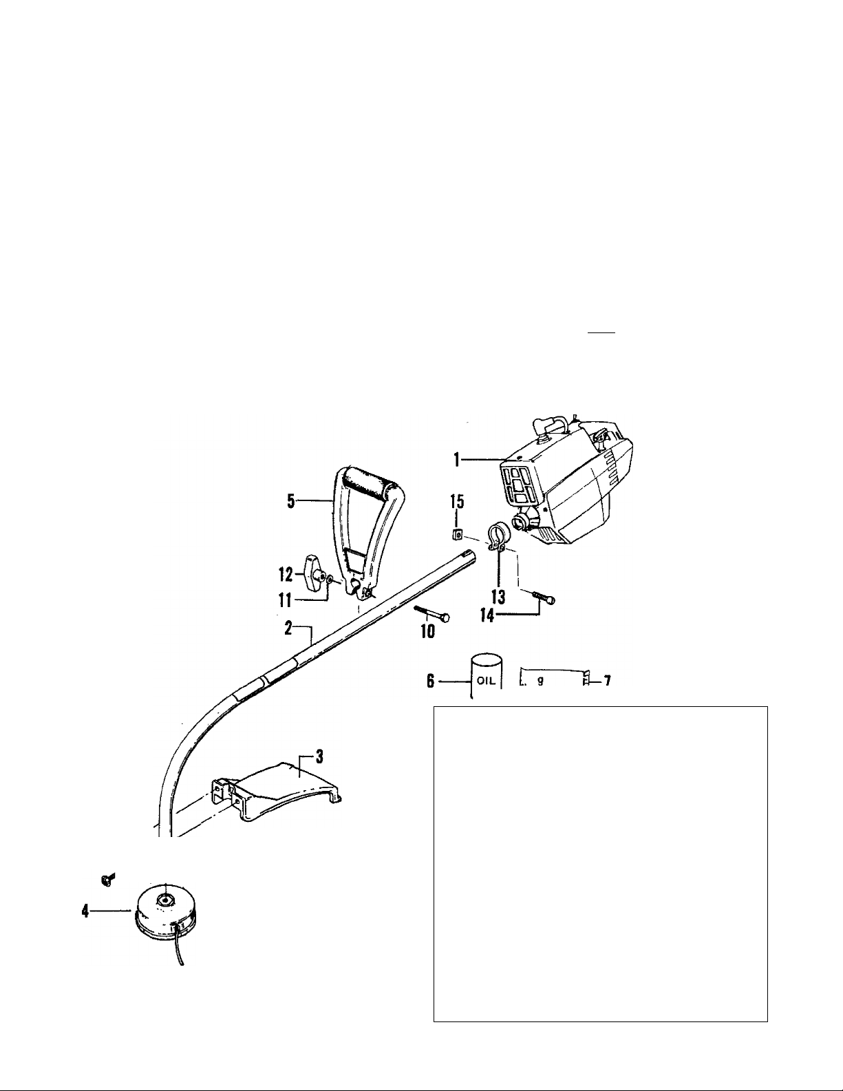
KNOW YOUR WEEDWACKER® TRIMMER
A. INTRODUCTION
Your WEEDWACKER® Trimmer Is a versatile product
developed for large lawns and to make short work of a
variety of lawn care tasks - trimming, mowing, edging,
sweeping, and scalping.
Special Features include;
• FUEL INJECTION STARTING™
• Adjustable assist handle
• Semi-automatic advancing line feed
• 17" inch cutting path
• Total weight -13 lbs,
-------------------
B. UNPACKING INSTRUCTIONS
1. Remove contents from the barton if you have not
done so.
2. Check parts against the list below.
3. Examine parts for damage.
4. Notify your Sears Store immediately if a part
is missing or damaged.
NOTE: A rattle like noise in a powerhead with an
empty fuel tank is a normal condition, caused by the
___
Jilter moving against the wall of Jhe^mpty tank.
8“i
3 grease
PL ■— FJ
KEY
1
Engine
2
Drive Shaft/Bearing Assembly
3
Splash Deflector
4
Cutting Head
5
Assist Handle
6
2-Cycle Engine Oil - 8 oz. can
7
Grease
Loose Parts Bag
8
Screw, Splash Deflector - 1/4-10x1-1/8"
9
Bracket, Splash Deflector
10
Hex Bolt, Assist Handle, 1/4-20x1-1/2"
11
Washer, Assist Handle, 1/4 flat
12
Knob, Assist Handle, 1/4-20
13
Clamp - Engine Shroud
14
Screw - Clamp -1/4 - 20 x 9/16"
15
Nut-1/4-20-Clamp
-
--
Operator’s Manual (not shown)
CARTON CONTENTS:
LOOSE PARTS BAG CONTENTS:
QTY.
1
1
1
1
1
1
1
1
2
1
1
1
1
1
1
1
Page 5

ASSEMBLY
A. PREPARATION
Your Operator’s Manual has been developed to help
you assemble the unit and to understand its safe opera
tion. It is important that you read your manual com
pletely to become familiar with the unit before you begin
assembly.
1. READ YOUR OPERATOR’S MANUAL.
2. Tools you will need:
z
1-1/4 inch Wrench
7/16 inch Wrench
3/8 inch Wrench
or
vS
b.
z®
Adjustable Wrench
z^
Slotted Screwdriver
B. ASSEMBLY STEPS
1. DRIVE SHAFT HOUSING — Figure 1.
a. Place clamp from loose parts bag on the engine
shroud as shown in Figure l.
b. Pull about 6 inches of the flexible drive shaft out from
the drive shaft housing.
c. Fit the end of the flexible drive shaft into the square
shaped opening inside the engine shroud. Figure l.
NOTE: Turn the engine as necessary to line up parts.
d. Align the groove in the drive shaft housing with the
key inside the engine shroud opening.
e. Firmly push the drive shaft housing straight into the
engine shroud until it bottoms out (about 1-1/2
inches).
f. Install clamp screw and square nut as shown in
Figure 1.
NOTE: The nut must be mounted on the tab side of
the clamp to keep nut from turning.
g. Tighten the clamp screw secu rely with a screwd river.
2. CUTTING HEAD — Figure 2
a. Hold the dust cup with a 1-1/4" wrench to keep the
dust cup from turning. Figure 2.
b. Thread the cutting head clockwise onto the arbor
shaft, against the dust cup, and as tight as possible
with your hand. Figure 2.
c. Press the tap button and pull the cutting line from the
head a minimum of 2 inches. Figure 3.
NOTE: To remove the cutting bead, hold the dust cup
' • with ad-1/4"'wrench and unthread the cutting head
counterclockwise
Page 6

3. SPLASH DEFLECTOR - Figure 4
a.
Locate the raised “V” ridge on the splash
deflector into the indented “V” slot on the
drive shaft housing. Figure 4.
b.
Rest the bottom of the splash deflector on top
of the drive shaft housing shoulder above the
dust cup.
NOTE: The bottom of the splash deflector
must rest on top of the shoulder of the drive
shaft housing.
Make sure the splash deflector is aligned
toward the engine as shown in Figure 5.
Install the bracket and screws as shown in
Figure 4.
Tighten the screws evenly and securely with a
3/8 inch wrench or a slotted screwdriver,
NOTE: It is possible that a small space will be seen
between the bracket and the splash deflector when
hardware is fully tightened.
4. ASSIST HANDLE — Figure 5
a. Align the assist handle on the drive shaft hous
ing above the decal(s), makifig sure the handle
curves back toward the engine. Figure 5.
b. Firmly push the assist handle over the drive
shaft housing.
c. Install the assist handle bolt, washer, and
knob as shown in Figure 5.
NOTE: Make sure the screw is placed on the side of
the handle with the hex-shaped screw opening.
d. Holdtheunltintheoperatingpositionandadjustthe
handle up or down thedrive shaft housing to a posi
tion comfortable for the user.
e. Tighten the knob by hand only.
NOTE: The assist handle can be rotated from left to
right allowing thecutting head to be tilted. Tilting the
angle of the cutting head is useful when trimming or
.......
cutting alarge, sloped
.
EN0INE INFORMATION
A. FUELING YOUR UNIT
1, FUEL MIXTURE
Ybur unit is powered by a 2-cycle engine which
line and a high quality engine oil specially made for
2-cycle air-cooled engines. The internal design of the
2-cycle engine requires lubrication of moving parts. This
lubrication is provided when you use the recommended
mixture of gaspline and oil.
Using the correct measure of gasoline to oil is very
Important. Too much oil in the mixture will foul the
sparkplug.
I CAUTIONfl Too little oil wilt cause the engine to
overheat and become seized.
Always mix the fuel thoroughlyinacontalner since
the gasoline and oil do not readily combine. Do nof
trytomixfueldimcOyin the fuel tank.
a. DO NOT USE.
Figure 5
• BIA OIL (Boating'IrtstltUte Of America) --
— Does not have proper additives for air-cooled
2-<^cl0 engines and can cause damage to your
unit.
................
• AUTOMOTIVE OIL-
— Does not have proper additives for 2-cycle
engines and can cause damage.
• GASOLINE CONTAINING ALCOHOL
(High Test, Premium or Gasohoi) —
— Stiffens critical carburetor fuel metering
elements and causes engine damage
from overheating.
— Increases vapor lock (causes hard starting).
— Attracts water causing corrosion damage.
Page 7

b. USE THE FOLLOWING:
3. IMPORTANT POINTS TO REMEMBER
#71-3B55S
16:1 Ratio
1 GALLON
regular
UNLEADED
GASOLINE
(¡I2pti
_^>>GINE O»
— OR —
GOOD GBfcoE
, 161 ^
COOLED, 2-C^CLt
^ EMfilNFOIL
_________
2. HOW TO MIX FUEL AND FILL TANK
a. Pour 1/2 gallon gasoline into an approved marked
container. Do not try to mix fuel directly in the fuel
tank.
b. Add entire measure of 2-cycle engine oil.
c. Cover container tightly and shake for one minute.
d. Add remainder of gasoline.
e. Cover container tightly and shake again.
f. Remove the fuel cap. Refer to “Spedfications”, page
2, for fuel cap location.
g. Fill the tank using a spout or funnel.
h. Reinstall the fuel cap securely.
B. PRE-OPERATION CHECKS
Before operating your unit, always;
1. ^ CHECK OVER SAFETY RULES AND PRECAU
TIONS in this Operator’s Manual. Make certain you
completely understand and follow each one.
2. ^ CHECK THE AIR FILTER
Clean the filter If dirty before operating the unit. For
location, see page 14.
a. Use only recommended fuel mixtures.
b. Eliminate all sources of sparks or flame in
the areas where fuel is mixed, poured, or
stored. There should be no smoking, open
flames or work that could cause sparks.
c. Use an approved, marted container for alt fuel
purposes.
d. M ix and pour fuel in an outdoor area. Store fuel
in a cool, dry, well-ventilated place. Gasoline
vapors are harmful to your health and can cause
serious hazards, such as explosion and fire.
e. Wipe up all fuel spills before starting the
engine.
f. Move at least 10 feet (3 meters) away from fuel
and fueling site before starting the engine.
3. ^CHECK THE UNIT FOR LOOSE BOLTS, NUTS,
OR FITTINGS.
Tighten, repair or replace parts as necessary. Tools
required are shown on page 5. Use only recom
mended, genuine Sears/Craftsman replacement
parts.
4. ^CHECK THE FUEL TANK.
Fill with a clean, fresh fuel mixture according to
instructions in fuel mixture section.
C. STARTING INSTRUCTIONS
1. HOW FUEL INJECTION STARTING™ WORKS
FUEL INJECTION STARTING™provides a . quick, start feature by. injecting a precise . amourit of fuel directly into the. carburetor
manifold which provides a rich fuel mixforthe
first few seconds of operation.
rh
CARBURETOR |
FUEL INJECTION STARTING DEVICE (PATENTPENDING)
Figure 6
GRAIN
• Each time the injector button is pressed and
■ released, fuel is forced from the fuel tank to
• ■ the accumulator chamber.
• The accumulator chamber provides a sec
ondary fuel supply until the carburetor can
obtain fuel through the primary line
• When the accumulator chamber is full, fuel
is injected into the carburetor manifold to
provide a rich mixture for starting.
• Excess fuel escapes through a drain to
prevent the engine from flooding if the
injector button is pressed too many times.
As a result, a few drops of fuel may appear
on the ground during the starting procedure.
• The number of injections required will
depend on temperature conditions and the
time elapsed since the engine was last
started.
Page 8
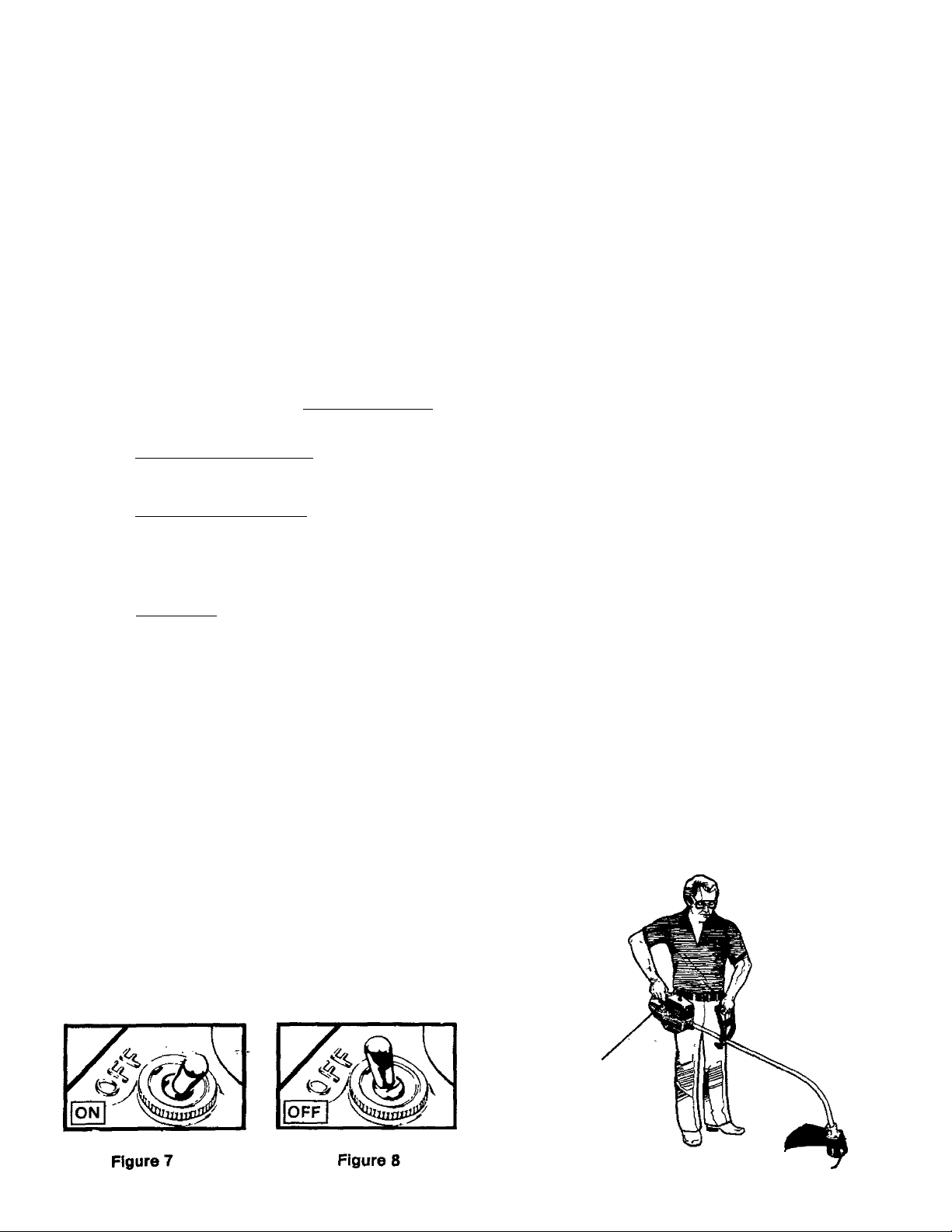
2. STARTING PROCEDURE
3. IMPORTANT POINTS TO REMEMBER
Extend aminimumof4 Inches of line from the
cutting head to provide the correct load on the
engine.
Stand in the operating position, and place
b.
the cutting head on the ground. Figure 9.
This insures that fuel will flow into the in
jector pump.
Move the ignition switch to the "ON" posi
c.
tion. Figure 7.
d. Grip the rear handle with your right hand,
squeezing and keeping the throttle trigger
fully depressed until the engine runs
smoothly.
e.
Press the injector button down fully allow
ing the button to return completely after
each pressing. Follow conditions and injec
tions listed.
Conditions
First Starting Out-of-Box
[Above 30° F Temperature!
— First starting/engine cold
— Restarting/engine hot
(Below 30°F Temperaturel
Required Injections
6
3-4
0-1
— (See “Cold Weather Starting",
this page.)
, Ointinue pressing and releasing the injector but
f.
ton until fuel drips out of the bottom of the unit.
I CAUTIONfl If more than a drop or two of fuel
spills on the ground move unit away to another
area for starting to avoid creating a fire hazard.
g. Pull starter rope quickly and sharply until
engine starts.
NOTE; If engine attempts to start but dies
or does not start after 5 (five) pulls, press
injector one more time and pull starter
rope again.
h. The engine wUI run roughly when first
started. It is important to keep the throttle
trigger fully , depressed until the engine
runs smoothly (10 seconds or less).
i. If the engine starts but the cutting head does
not turn with the throttle trigger depressed,
make sure the drive shaft housing is properly
seated in the engine shroud. See “Drive Shaft
Housing", pages.
a. If the engine starts to die immediately after
starting, keep throttle trigger depressed
and press injector button once with fore
finger to give unit additional fuel.
b. If the engine is stopped momentarily (less
than 5 minutes), it probably will not require
an injection.
c. If unit runs out of fuel or is drained for stor
age “First Starting" procedure may be re
quired because
the system will be dry.
d. After starting and engine runs smoothly,
keep unit running at half speed until engine
is warmed up to proper idle.
e. Using gasoline or fuel mix over 2 months old
will cause the engine to be difficult or impos
sible to start!
4. COLD WEATHER STARTING
(Below 30° F)
a. Follow “Starting Procedure" through step
“d", then as below.
b. Press injector button down fully six (6)
times allowing the button to return com
pletely after each pressing.
c. Pull starter rope quickly and sharply until
unit starts. Keep trigger fully depressed.
d. If unit does not start in four pulls or attempts
to start but dies, press injector button an
additional four times.
e. Continue pulling starter rope four pulls,
if unit fails to start, repeat step d., above.
f. It is important not to release trigger until
unit runs smoothly.
g. Once unit has started, immediately press
injector button two additional times to keep
unit running until it warms up.
h. In extremely cold weather, it will be very
difficult to flood the unit, so if the unit
- ■ doesn’t start quickly, do not hesitate to
press injector button for additional fuel.
i. For starting warm engine in cold tempera
tures, press injector button once before
starting.
^WARNING
The cutting head must not turn when the engine
runs at Idle speed. Refer to “Carburetor Adjust
ments”, page 9 for correction.
FUEL
INJECTOR
BUTTON
Figure 9
Page 9

OPERATING INSTRUCTIONS
For maximum performance and efficiency:
1. Always accelerate the engine to the desired
speed before cutting.
2. Never operate the engine at a higher speed
than necessary.
3. Always release the trigger and allow the en
gine to return to idle speed when not cutting.
Make sure the cutting head stops turning
when the throttle trigger is released and the
engine runs at idle speed. For correction,
refer to “Carburetor Adjustments," below.
Stop engine by moving the ignition switch, to
the “OFF" position (Figure 8).
ENGINE ADJUSTMENTS
1. CARBURETOR ADJUSTMENTS
The carburetor has been carefully adjusted atthe factory.
Due to changes in altitude and operating conditions, your
carburetor may require adjusting. Tb make the adjust
ment follow the procedure below very carefully:
a. PREPARATION
1. ) Use fresh fuel mix with proper gasoline/
' oil ratio. See "Fuel Mixture”, page 7.
2. ) Make sure the cutting line extends at least
4 inches to provide correct load on engine.
3. ) Remove air filter ( Figure 10 ) and place
under spark plug wire for safe keeping.
4. ) Turn both low speed and high speed mixture
screws clockwise ^ A until fully closed,
but do not overtighten. Figure 10. Unscrew both
mixture screws one full turn counterclockwise
b. IDLE SPEED ADJUSTMENT
1. ) Turn Idle Speed Screw clockwise
until it stops. Do not overtighten. Open
screw one full turn counterclockwise.
2. ) Start the engine and cut grass for 3 min
utes to warm up engine.
3. ) Allow engine to idle.
4. ) Adjust Id le Speed Screw until engine continues
to run without stalling and without the cutting
head turning.
Turn screw clockwise to increase
engine speed if engine stalls;
Turn screw counterclockwise to slow
engine down if cutting head
continues to turn.
i CAUTION:
are highly critical adjustments. If set incorrectly per
manent damage will occur to the engine. Both the
low speed mix and the high speed mix sc/eivs
should be in the range of 3/4 to 1-1/4 turns open.
I
High and low speed mixture settings
c. LOW SPEED MIXTURE ADJUSTMENT
Allow engine to idle.
1.)
2.)
Turn Low Speed Mixture Screw clock
wise slowly. Note the position at
which the engine speed is increased.
3.)
Turn the screw slowly counterclockwise.
A . Note the position at which the
speed Is reddeed.
4.)
Set the screw mid-way between these two
extreme positions.
d.
IDLE SPEED ADJUSTMENT
1. ) Allow engine to idle.
2. ) Adjust the Idle Speed Screw until the
engine idles as fast as possible without
the cutting head or blade turning
ICAUTIONH Do not operate engine at full throttle
for prolonged periods while making high speed
adjustments as damage to the engine can occur.
e. HIGH SPEED MIXTURE ADJUSTMENT
1 ) Support the shaft so that the cutting head
is off the ground and will not contact anv
object.
2.
Squeeze throttle trigger wide open
3.
Turn the High Speed Mixture Screw slowly
clockwise until the engine speed is
reduced. Note position.
4.
Turn the screw slowly counterclockwise
Stop when the engine just begins
to run rough. ^
5.} Turn the screw slowly the minimum
amount clockwise-until the engine
runs smoothly.
f. CHECK ACCELERATION
Allow the engine to idle. Squeeze trigger and
check engine acceleration. If the engine
does not accelerate smoothly, you may have
to repeat steps “b.3.)" through “e."
NOTE: Generally, by turning the low speed
screw counterclockwise A“*«* a small amount,
the unit will accelerate properly.
Figure 10
g. REINSTALL AIR FILTER
I CAUTION: I The air filter must be fitted into the
corners of the housing to avoid engine damage.
2. SPARKPLUG
Check spark plug periodically and replace as necessary.
Set the electrode gap at .025".
Page 10

USING YOUR UNIT
Your Trimmer is equipped with a semi-automatic advancing
cutting head that cuts with the tip of a monofilament nylon line.
* The nylon cutting line will easily remove grass and
weeds from around walls, fences, trees, and flower
beds, but it also can cut the tender bark of trees or
shrubs and scar fences. For this reason, it is very
important to learn the proper techniques of cutting
around and near objects.
• The nylon cutting line will wear faster and will
require being advanced more frequentiy when you
are cutting against rocks, bricte, concrete, metal fences,
etc., than against trees or wooden fences.
• The cutting head wiil wear prematureiy:
— if aliowed to continuousiy contact the ground
during normal cutting.
—if the line limiter is not kept sharp.
Ж WARNING
Use only flexible, non-metalic, monofilament cutting
line. Do not use other materials such as rope, wire, etc.
Wire can break off during cutting and become a
dangerous missile.
A. OPERATING INSTRUCTIONS
1. Read your Operator’s Manual.
Make certain you completely understand and follow
all safety rules, precautions, and operating instruc
tions before operating the unit.
Always wear eye protection. The
^lash deflector/line Umiter will not
prei^nt rocks and debris from being
thrown or ricocheting into the eyes
and fbce which can result in loss of vision or
serious personal injury.
3. Dress safely in long pants and wear boots or
safety shoes.
Do not wear loose clothing, jewelry, short pants or
sandals; or go barefoot.
4. Check the unit before operation.
Look for worn, loose, missing, or damaged parts. Do not
use until the unit is in proper working order.
5. Inspect the area to be cut.
Remove all debris and objects that can ricochet, be
thrown, become entangled in the cutting head or other
wise cause injury or damage during cutting.
6. Keep observers, children, bystanders, and animals
safely m№iy.
Before starting the engine and during operation, make
certain children, animals and bystanders are away from
the work area - a minimum of 30 feet (10 meters).
B. ADVANCING THE CUTTING LINE
* The cutting fine is extended semi-automatically by
tapping thetmttom of the head on the ground with
the engine running.
* Approximately 2 Inchesof line 1s extended each
time the tap button is tapped on the ground.
* The line limiter on the splash deflector cuts line to
a maximum aliowable length.
* The most efficient cutting line length is the max
imum length allowed by the line limiter.
1. To advance line;
a. Operate the engine at full throttle.
b. Hold cutting head parallel to and above the
grassy area of the ground.
c. Tap the cutting head lightly on the ground one
time. See Figure 12. Approximately 2 inches of
line will be advanced after each tap.
NOTE: If the line is worn down to two inches or
less, more than one tap may be required to
obtain the most efficient line cutting length.
10
2. Always keep the splash deflector in place when
the unit is being operated.
3. Keep the line limiter sharp for fost, easy cut-off.
See page 13 for sharpening instructions.
NOTE: Always tap the cutting head on a grassy
area of the ground. Tapping on surfaces such
as concrete or asphalt can cause excessive
wear to the cutting head.
LINE
LIMITER
CUTS EXCESS
LINE
Figure 12
TO ADVANCE
CUTTING LINE,
TAP LIGHTLY
ON GROUND
ONE TIME
Page 11

C. CUTTING METHODS
• The tip of the line does the cutting. Allow the unit
to trim at its own pace. You will achieve better results
by not crowding the line into the cutting area. The right
way and wrong way are shown in Figure 13.
• Always cut left to right.
AWARNING
Always wear eye protection. Never lean overthe
cutting head. Rocks or debris can ricochet or be
thrown into eyes and face and cause loss of
vision or serious personal injury.
1. TRIMMING — Figure 14
Hold the cutting head at a 30 degree angle to the
cutting area for efficient trimming. Do not force the
cutting line intothe work area. Allow the tipof the line
to do the cutting.
2. EDGING — Figure 15
Adjust yourtrimmer for edging byturningtheengine
upside down so the drive shaft housing angles out
rather than down. Rotate the assist handle on the
shaft, placing it in an up, usable position. Hold the
cutting head above the area to be edged as shown
and operate the throttle trigger with your thumb.
3. MOWING — Figure 16
Yourtrimmer is ideal for mowing in places conventional
lawn mowers cannot reach. In the mowing position, the
cutting line is parallel to the ground. Avoid ietting the cut
ting head continuously contact the ground as this can
cause damage to your unit as well as scalp the ground.
4. SCALPING —Figure 17
To remove unwanted vegetation around trees, posts,
monuments, etc., maintain a30 degree angle with the
cutting head and allow the tip of the cutting iine to
strike the ground.
NOTE: Increased line wear is to be expected when
using scalping techniques.
5. SWEEPING —Figuréis
For quick and easy clean up extend the line to the
length allowed by the line limiter and move the unit
from side to side, keeping the cutting head parallel to
the surfaces being swept.
11
Page 12

O. CUTTING HEAD MAINTENANCE
1. CUTTING LINE REPLACEMENT
a. Hold the cutting head as shown In Figure 18.
Press the lock tab, and turn lock ring counter
clockwise .
b. Remove the lock ring, tap button, and
spool. Figure 19.
c. Clean dirt and debris from housing and
spool.
d. Inspect spool. Replace as necessary. See
instruction #3 this section.
NOTE: The aluminum line saver is reversi
ble. After a groove is worn into one side,
reverse the line saver (with the spool
removed) to provide a new wear surface.
Figure 21.
e. Replace a worn spool with a new pre-wound
spool for quick easy replacement. Or as an alter
native, replace nylon line on existing, usable
spool. To replace line, insert 1/16 to 1/8 inch of the
end of the line through the hole in the spool. Wrap
the line evenly onto the spool in a clockwise
direction as shown by arrow on spool.
Figure 20.
f. Insert the end ofthe line through the tine saver as
shown in Figure 21. Push spool in housing. Force
spool down. Turn and lock spool underthe drive
lugs on the drive gear.
g. Replace the tap button; press lock tab and
install the lock ring. Turn the lock ring
clockwise and fasten under the
catches on the housing. Figure 22. Check
to be certain all catches are properly se
cured.
Figure 19
Page 13

h. Pui! on the nylon line to change the spool from the
locked position to the operating position. Figure 24.
i. Obtain c»rrect line length by pressing tap button and
pulling on nylon line again.
NOTE: Approximately 2 inches of line can be
advanced each time the tap button is pressed.
Figure 24.
USE ONLY SEARS/CRAFTSMAN®
REPLACEMENT PARTS
2. CUTTING LINE REPAIR
If the cutting line breaks off or backs up in the
cutting head, follov/ “Cutting Line Replacement”,
omitting step “e”.
3. SPOOL REPLACEMENT
a. Replace the spool when: The square corners of
the drive lugs are rounded off, reduced in size, or
broken off. Figure 25.
b. To replace the spool, follow “Cutting Line
Replacement” (page 12).
4. LINE LIMITER MAINTENANCE
• The line limiter is the metal blade found on the
splash deflector.
•' The fiheTImiter must be kept sharp to:
— allow fast, easy cut-off.
— avoid excessive wear to the cutting head.
• To sharpen:
Use a flat file and file from the outside toward the
inside of the line limiter. Figure 26.
NOTES
NORMAL SPOOL
WORN SPOOL
Figure 25
13
Page 14

GENERAL MAINTENANCE
A. DRIVE SHAFT LUBRICATION
• Lubricate the Flexible Drive Shaft:
— After each ten (10) hours of operation:
— Before operating if the unit has been stored
for 90 days or longer.
• Use gear grease stock #28-59071.
NOTE: A tube of grease has been supplied with your
unit to be used after the first 10 hours of operation.
NOTE: Check the Flexible Drive Shaft for
wear or damage. Replace if broken wires,
twists or kinks are found.
CAUTION: Lay the Flexible Drive Shaft on a
clean surface. Avoid laying the shaft on the
floor, ground or on any surface that may have
dirt or debris. Even after wiping the shaft,
grease residue can pick up dirt particles that
can cause damage or premature failure.
• Observe the following procedure for best
results:
I CAUTION: I Avoid bodily contact with the muffler
area when the engine is warm. Always replace
the muffler guard if it becomes damaged or
broken.
1. Loosen the Pinch Clamp Bolt and remove the
Drive Shaft Housing from the Engine Shroud.
2. Remove the Flexible Drive Shaft as shown in
Figure 26.
3. Using a clean cloth, thoroughly wipe the sur
face of the Flexible Drive Shaft to remove any
old grease that may be presentr
4. Apply a uniform coat of gear grease to the entire sur
face of the Flexible Drive Shaft. Figure 27.
5. Inject the remaining contents of the tube sup
plied with the unit into the top of the Drive
Shaft Housing.
6. Replace Flexible Drive Shaft in the Drive
Shaft Housing.
7. Follow the instructions on page 6 to replace
Drive Shaft Housing in the Engine Shroud.
AIR FILTER CARE
A dirty air filter decreases engine performance
and increases fuel consumption.
Clean the Air Filter:
• Frequently,
• Always after 5 tanks of fuel or 5 hours of opera
tion, whichever is less.
Follow these steps:
1. Remove the airfilter (located atthe bottom, rear of the
Engine Shroud) see page 2.
2. Wash in soap and water.
1
CAUTIONTI Do riot clean filter in gasoline
or other flammable solvent to avoid creating
a fire hazard.
Squeeze filter dry.
3.
4.
Replace the air filter,
14
I CAUTION:~l The air filter must be fitted into
the corners of the housing to avoid engine
damage.
Figuré 27
C. FUEL TANK UPKEEP
Never use gasoline that is more than 2 months
old in a fuel mixture. Gasoline begins to break
down after a period of time and will form com
pounds that cause hard starting and damage in
2-cycle engines.
1. inspect the unit for fuel leaks each time it is
used. Repair or replace parts as necessary.
2. Using gasoline or fuel mix over 2 months old will
cause the engine to be difficult or impossible to
starti
3. Drain the fuel tank or allow the unit to run out
of fuel before storing for 30 or more days.
NOTE: "First Starting” procedure may be
required fora unit that runs out of fuel or from
which fuel is drained. See "Starting Instruc
tions", page 8.
Page 15

D. STARTER ROPE REPAIR
• Repair the starter rope If the rope breaks next
to the pulley.
• Replace the starter rope if the rope breaks 2-3
inches away from the pulley as the rope will be
too short to repair properly.
Awarning
Always wear eye protection when ser
vicing the starter rope. The recoil spring,
located beneath the pulley, is under ten
sion. If the spring pops out, serious per
sonal injury can result.
• To repair or replace:
NOTE; Use caution when separating the
fan housing from the shroud to avoid
breaking or damaging the fuel line fittings.
1 . Drain all fuel from tank.
2. Remove the four (4) screws from fan
housing. Figure 28.
3. Carefully separate fan housing from shroud
about one {1) inch.
4. Disconnect fuel lines from fittings.
5. Disconnect ignition module wires. Figure
28.
6. Slide high tension lead grommet from slot
in fan housing.
7. Separate the fan housing completely from
the shroud.
8. If the starter rope is not broken, release
the spring tension by pulling about 12
inches of rope from the pulley and catch
the rope in the notch as shown. Figure 30.
NOTE: The tension on the starter spring
will be released if the rope has broken.
9. Remove screw and pulley very carefully.
Figure 29. The recoil spring which lies
beneath the pulley must stay In the hous
ing, flat against the bottom, lithe spring Is
disturbed, it will require considerable time
and effort to reinstall. Twist the pulley
gently clockwise as you pull up to
release the spring,
10. Moveawayfromthefueltankandmelttheendof
the new rope to go into the pulley.
11. Allowthemeltedendtodr{ponce,thenwhilerope
is still hot pull the melted end through a clean rag
to obtain a smooth, pointed end.
12. Insert rope through the rope exit hole in
the fan housing.
13. Guide rape inside pulley, then up through topside
pulley hole by pushing the rope from the under
side hole with a small object such as a
screwdriver.
14. Wrap rope counterclockwise around
pulley ratchet and tuck loose end back
under rope leaving a 1 /4 to 1 /2 inch
tail laying in the rope groove. Figure 30.
15. Wind all but about 12 inches of the rope
counterclockwise around pulley.
16. Replace pulley in the housing. Be sure
the pulley is all the way down and the
spring is secured. Replace screw and
tighten. Figure 29.
17. Hold the 12 inch slack in the rope and
catch rope in pulley notch. Figure 30.
18. Hold the rope taut and make 2 complete
turns of the pulley counterclockwise
to place tension on the pulley.
Hold the pulley to retain tension.
19. Align pulley notch with rope exit hole,
pull starter handle to the full extent of the
rope and allow the rope to slowly wind
around the pulley.
NOTE: While the unit is disassembled, in
spect the carburetor housing seal and
replace if worn. Figure 28.
20. Reverse procedure for re-assembly of fan
housing to shroud.
NOTE: Make sure the fuel line with the
black stripe or solid color is installed on
Jhe inner fuel fitting.
GROMMET
SHROUD
CARBURETOR
HOUSING seal:
FUEL LINE FITTINGS
IGNITION MODULE WIRES
FAN
HOUSING
FUEL LINES
Figure 28
Figure 30
15
Page 16

TROUBLE SHOOTING CHART
TROUBLE
Engine will not start
Engine will not idle
properly
Engine will not
accelerate, lacks
power or dies
under a load
Engine smokes
excessively
Engine runs hot
Unit engages at
idle speed
Cutting head doés not
turn when engine is
accelerated
Cutting head stops
underaload
Cutting line does
not advance.
CAUSE
1. Ignition switch off.
2. Fuel tank empty.
a Spark plug not firing,
4. Fuel not reaching carburetor.
5. Engine flooded.
6. Compression low.
1. Idling speed set too low.
2. Idle speed set too high.
1. Move switch to “Start”.
2. Fill tank with correct fuel mixture,
a Install new plug.
4. Check for dirty fuel filter; clean. Check
5. See Starting Instructions.
& Contact your Sears Service Center.
1. Adjust idle speed screw clockwise to
2. Adjust idle speed screw counter
clockwise to reduce speed,
a Low speed screw requires adjustment.
4. Crankshaft seals worn.
5. Compression low.
1. Carburetor requires adjustment.
2. Air filter dirty.
a Spark plug fouled.
4. Carbon build-up.
5. Low compression.
1. High speed needle requires adjustment.
2. Air filter dirty.
a Oil rich fuel mixture.
1. Fuel Mixture Incorrect.
2, Spark Plug Incorrect,
a Carbon build-up.
4. High Speed Mixture set too low.
1. C^uretor requires adjustment.
2. Clutch requires repair.
1. Drive shaft not engaged.
2. Carburetor requires adjustment,
a Clutch slipping.
1. Drive shaft not engaged.
2. Carburetor requires adjustment,
a Clutch slipping.
1. Line improperiy wound onto spool.
2. Drive.gear damaged or worn,
a Worn spool.
a See Carburetor Adjustments.
4. Contact your Sears Senjice Center.
5. Contact your Sears Service Center.
1. See Carburetor Adjustments.
2. Clean or replace air filter.
a Clean or replace Spark Plug and regap.
4. Clean exhaust system including spark
5. Contact your Sears Service Center.
1. See Carburetor Adjustments.
2. Clean or replace air filter.
a Empty fuel tank and refill with correct
1. See Fueling Your Unit.
2. Replace with con-ect plug.
a Clean exhaust system including spark
4. See Carburetor Adjustments.
1. See Carburetor Adjustments.
2. Contact your Sears Service Center.
1. See Assembly Instructions.
2. See Carburetor Adjustments.
a Contact your Sears Service Center,
1. See Assembly Instructions.
2. See Carburetor Adjustments. a Contact your Sears Service Center,
1. Rewind spool.
2. Replace drive gear,
a Replace spool.
REMEDY
for kinted or split fuel line; repair or
replace.
increase speed.
arrestor.
fuel mixture.
arrestor.
16
Page 17

ACCESSORIES
A. ACCESSORIES
2-Cycle Engine Oil
Gear Grease (14-1/2 oz.)................................................................Stock No.
Spark Plug
Replacement Cutting Head
Spool WA.ine
Nylon Cutting Line
Shoulder Strap Kit .........................
....................................................................................Part No.
........................................................................
...........................................................Stock No.
.............................................................................
.......................................................................
..........
............
......
.....
......
Stock No.
Stock No.
Stock No.
Stock No.
NOTES
71-36555
28-59071
STD361258
71-85764
71-85789
71-85778
71-85783
17
Page 18

SEARS WEEDWACKER® PARTS LIST - MODEL 358.796131 -26.2cc
Figure 1
18
Page 19

SEARS WEEDWACKER® RARTS LIST ~ MODEL 358.796131-26.2cc
Figure 1
KEY
NO.
1
RAFTT
NO.
706515 1
QTY.
REa
DESCRIPTION
Cutting Head Assembley
Stock #71-85764 (Incl. 2-9)
2 93896
3
4
5
6
7
8
9
10
93898 1
92067
92068
93897
706502 1
-93387-
....
92133
92243
1
1 Spring
1
1 Drive Gear
1
1
2 Screw-1/4-10x1-1ffl-Splash
Hub w/Line Saver
Line Saver
Ad^tor-Spring
Spool w/Line-Stock #71-85789
-Release-Button Cover
Deflector
11
12
93653
93716
14 94440
15
19
20
15337 2
93853 1
STD
1
1 Dust Cup
1 Splash Deflector
2 Nut-10-24-Locking
Bracket - Splash Deflector
Screw - 10-24x1 - Line Limiter
Line UmKer
540410
Key No's Excluded: #13,16-18,21-24.
KEY
NO.
PART
NO.
25 10618
26
92059 1 Knob-1/4-20
27 STD 1
551025
28
STD 1
522517
29 94439
30 93936
31 _3fl-102L
32 66706
Decals
101 26593
102 27153 1
103
104
26674 1
26570 1
QTYl
REQ.
1
DESCRIPTION
Assist Handle
Washer-1/4-Rat
HexBolt-1/4-20x1-1/2
1
1
_ — Gear Grease Stock #28-59071
1
Drive Shaft Housing
Rexible Drive Shaft
—
Operator’s Manual
Warning Label - Assist Handle
Decal - Warning (Shaft)
Decal - Weedwacker
Decal - Splash Deflector
19
Page 20

SEARS WEEDWACKER® PARTS LIST - MODEL 358.796131-26.2cc
Figure 2
20
Page 21

SEARS WEEDWACKER® PARTS LIST — MODEL 358.796131 -26.2cc
Figure 2
KEY
NO.
1
PAFTT
NO.
24436 • 1
QTY.
REQ.
DESCRIPTION
Bumper Fuel Tank Housing
2 26566 1 Handle & Fuel Tank Housing
26567 1 Handle Cover
3
d
24365 1 Trigger-Throttle
24371
5
23575
6
7
STD 1 Screw - 8 -16 X 3/4 Ffen Head -
1 AirRfter
1 Nut - Grounding Switch
610807 Handle Cover
8
69182 1
Kit - Grounding Switch .
(lncl.#^10 &39, this page
and #12 from page 23)
15706
9
2
Screw-10-24x1 -1/2-Sems
Fan Housing - Top
10
11
24569 1
15582 2
Washer - Ground Terminal
Screw -10 - 24 X 5/8 - Sems 36
Fan Housing - Bottom
12
13
24461 1 Trigger-Spring
15367 5 Screw -10 -14 X 3/4 - Fan
Housing to Handle & Fuel
Tank 41
14 26109
15
16
21052 1 Line-Fuel Inlet
10729 1 Fuel Cap Assembly
1 RIter- Fuel (Inlet Line)
(Ind. 6-Ring)
18
22290
19 21053
20
26931 1 Fuel Pick-Up Assembly
21 69178
22
23
24
42067 1 Starter Recoil Spring
26035 1 Air Baffle
15544* 2 Screw - #10 X 3/8 plan Hd.-
1 Rope (35 ft)
1 Line - Pump to Accumulator
1
Ffen Housing Kit
Air Baffle
25
26048
1 Starter Pulley
KEY
NO.
26
27
PART
NO.
OTY.
REQ.
15123 1
15479 1
DESCRIPTION
Washer#10 Starter Pulley Screw
Screw - #10 X 3/4 - Hex Washer
Head - Starter Pulley
28
29 10738 1
30 15563*
26032 1 Iniector Button
Pump Assembly (lncl.#19)
1
Screw - #10 X1 - 3/16 Plastite
Air Baffle / Pump Mounting
31
32 21054 1
33 26178 1
26119 1
Check Valve - Duck Bill
Fuel Line - Tank to Accumulator
Clip - Retainer - inlet Line -
Fuel Tank
34
35
26548 1
10773
Shroud
1
Fuel Tank Assembly (Incl. #14,
15,16,2031,32 & 33)
15590 2
Screw -10 - 2 X 5/8 Binder Head
37 15^9 1 Screw-Pinch Clamp-1/4-20x9/16
38
39
40 15610
26560 1
39122 1
Clamp
Lead Wire - Ground
1
Nut #12-24 Square
26792 1 Ass'y. - Rope and Handle-
Starter (Incl.# 18)
42
STD 4 Screw -10 - 24 X 7/8 - Fll. Hd.
511010 Shroud
43
15274 4
Washer - Flat, #10 Narrow
Shroud
Decals
101
—
27153 1
26568
1
Decal - Instructions
Decal - Shroud (Right)
(not shown)
—
26569
A Decal-Shroud(Left)
-(not shown)
*lf your unit has been senflced with the metai fen housing, use Part No. 15373 (Screw - #10 - 24 x 1/4 - Fil. Hd.), instead of 15544
(Key No.24), and Ffert No. 15305 (Screw - #10 • 24 x 1 > 3/16 Fli. Hd.), instead of 15563 (Key No30).
Key No’s Excluded: #17
21
Page 22

SEARS WEEDWACKER® PARTS LIST - MODEL 358.796131-26.2cc
Figure 3
22
Page 23

SEARS WEEDWACKER® PARTS LIST — MODEL 358.796131 -26.2cc
Figure 3
KEY
NO.
1
2
PART
NO.
42059 2
STD 1
541131
3
4
5
15127
39114
STD
551008
6
7
8
g
10
11
12
13
14
15
16
17
18
19
20
69181
19059 2
15168 4
10316 1
39103
24435
25995
15235
10677 1
19128
15565
39082 1
3934
3933
STD
361258 51
21
22
23
15126
23373
26177 1
24 10651
25 24302
26
27
28
29
30
—
15162 2
32058 2
15351 2
24438
QTY.
REQ.
DESCRIPTION
Spring - Starter Dog
Nut-Flywheel-(5/16x26)
1 Washer-Flywheel
1
2
Flywheel Assembly (Incl. #1)
Screw-8-32x3/4-Fil.Hd.-
Ignition Module
1
Kit - Ignition Module
Seal - Crankcase
Screw - Crsuikcase
Crankcase AssV-(lncl.#7 & 28)
1
High Tension - Lead Assembly
(Incl.ih7,18&19)
1 Grommet - Plug Wire
1 Electrical Tab
Screw-8-18x9/16
2
Cap Assembly - Accumulator
(Incl. Cap, Screen & “0" 44 32057
Ring) 45
1
O-Ring - Accumulator
Chamber
Screw - 8-18x1'- Accumulator
2
High Tension Lead Wire
1 Boot-Spark Plug
1
Connector • Spark Plug Lead
1 Spark Plug (CXJ-14) 50
1
1
KiBy-Hywheet
Boot-Throttle
Throttle Wire (Red)
1
Accumulator Assembly
(Incl. #14,15 & 34)
1
. 1
Gasket-Cylinder
Ring - Piston
Retainer-Wrist Pin
Bearing - Crankcase
Washer - Thrust - Crankcase
1
Reed Valve
KEY
NO.
31
32
PART
NO.
19108 1 Gasket - Carburetor Case to
19105
33 21055
34 19131
35
36
26047
STD
610805
37
STD
610603
38 23367
39
15239 •
40 12070
41
26949
42 24903
43
22198
26675
46
47
48
49
26046
19115
35183
15566
24364
24361
52
53
54
55
56
57
58
24362
69196
69194
24932
24855
10797,
30054
QTY.
REQ.
DESCRIPTION
Crankcase
1
1
Seal - Carburetor Case
Fuel Line - Carburetor
1 O-Ring (Orifice)
1 Cover - Carburetor Case
4 Screw - 8 -18 X 9/16 - Pan
Hd. - Carburetor Case Cover
1
Screw-6 -19 X 5/15 - Pan Hd.-
Reed Valve
1 Washer - Reed Valve Screw
2 Screw -1/4 - 20 X 3/4 - Hex
Socket Hd. - Cylinder
1 C^inder
1
2 Spring - Muffler Detachment
1
1
Diffuser-Muffler
Piston Kit(lncl.#26,27&Pin)
Bearing - Wrist Pin
1 Crankshaft & Rod Assembly
1 Carburetor Housing
1
1
Gasket-Carburetor
Cartauretor - WA -149 -
(See Page 24 for Assembly)
2
Screw-10-24x2-1/4”-
Fil. Hd. - Carburetor
1
1
1
1
1
Screen - Spark Arresting
Cover-Muffler
Body-Muffler
Kit-Clutch Washer
Kit - Clutch Assembly (Incl.
Clutch Washer)
2
1
, 1,...
1
Spring - Muffler Guard
Guard - Muffler
Coupling & Bearing Assembly
• Sealant - Crankcase
(Not Supplied With Unit)
23
Page 24

SEARS WEEDWACKER® PARTS LIST — MODEL 358.796131-26.2cc
CARBURETOR NUMBER 35183
Figure 4
KEY
NO.
1
2 35191
3
4
5
6
7
8
9
10
11
12
13 35141
14
15
16
PART
NO.
35017
35164
35156 1
35178
35166 1
35133 1
35007
35138 1
35015 1
35132 1
35023
35106
35031 1
35031
QTY.
REQ.
1
1
1
Screw - Pump Cover
Pump Cover Ass'y. (Incl. #4)
*+ Gasket - Pump
. Screw-Idle Adjustment
1-.
+ Screen - Inlet
*H- Diaphragm - Pump
Valve - Throttle
1
Clip - Throttle Shaft
Spring - Throttle Return
•+■ Screw - Throttle Valve
Shaft Assembly - Throttle
1
1
1
1
Spring - Idle Needle
Needle - Idle
+ Spring - Metering Lever
+ Valve - Inlet Needle
-1- Lever - Metering
-♦-Contents of Kwik Repair Kit
24
DESCRIPTION
KEY
NO.
17
18
19
20
21
22
23
24
25
26
27
_
PART
NO.
35036
35142
35028
35016
35147
35042
35137
35151
35014
35153
35149
35185
35186
QTY
REQ.
1
1
r
1
■1'
1
1
1
1
4
1
1
1
DESCRIPTION
Spring - Hi Speed Needle
Needle - Hi Speed
+ Pin - Metering Lever
Screw - Metering Lever Pin
'+ Gasket - Circuit Plate
■ Plate-Circuit
+ Screw - Circuit Plate
■+ Gasket-Metering Diaphragm
+ Diaphragm Ass’y- - Metering
Screw Assembly - Metering
Cover & Throttle Shaft Clip
Cover- Metering Diaphragm
Kit - Kwik Repair Kit
(Not Shown)
Kit - Gasket / Diaphragm
(Not Shown)
Page 25

NOTES
25
Page 26

NOTES
26
Page 27

QUICK REFERENCE PAGE
Read and follow all Safety Rules, Precautions and Operating Instructions.
Failure to do so can cause in serious personal injury.
PAGE
PREPARATION
1. Know ail safety rules and precautions in this manual.
2. Wear safety glasses or goggles for eye protection
3. Dress safely - 1хю18 or safety shoes, long pants.
4. Check for worn, loose, missing or d^aged parts and repair.
5. Inspect and ensure the area to be cut is safe.
6. Keep children, bystanders, and animals a minimum of 30 feet (10 meters) away from the work area.
FUELING.....................................................................................................................................6-7
1. Eliminate all sources of sparks or flame where fuel is mixed, poured or stored.
2. Use fuel not over 2 months old.
3. Mix and pour fuel in an approved, marked container in an outdoor area. .
4. Use 1 part air-cooled, 2-cycle, engine oil to 16 parts regular unleaded gasoline.
5. Move a minimum of 10 feet (3 meters) away from fuel and fueling site before starting engine.
STARTING THE ENGINE ..............................................................................7-8
1. Extend a minimum of 4 inches of line from the cutting head.
2. Place unit on ground away from objects and on-lookers.
3. Keep the throttle trigger depressed until engine runs.
4. Press injector button as indicated on page 8.
5. Pull the starter rope sharply and quickly.
...... ..............................................................................................................3
OPERATING THE UNIT
1. Accelerate the engine to the desired speed before cutting.
2. Release the trigger and allow the engine to idle when not cutting.
3. Make sure the cutting head stops turning when the throttle trigger is released.
4. Stop the engine by moving the ignition switch to the “off" position.
ADVANCING THE CUTTING LINE ................................................................................................. 10
1. Operate the engine at full throttle.
2. Hold cutting head parallel to grassy area of ground.
3. Tap cutting head lightly on the ground once.
MAINTENANCE..............................................................................................................................14
1. Drain all fuel from the unit before storing for more than 30 days.
2. Disconnect spark plug before performing any maintenance except for carburetor adjustment.
3. Clean air filter frequently but always after 5 hours of operation or 5 tanks of gas whichever is less.
4. Lubricate the flexible drive shaft after each 10 hours of operation and after storing for more than 90 days.
5. Store in a dry place out of the reach of children.
.............
................................................................................................ 9 -11
27
Page 28

The Model Number will be found under the handle with the Serial
Number. Always mention the Model Number when requesting service
or repair parts for your unit.
All parts listed herein may be ordered from any Sears Service Center
and most Sears Stores.
WHEN ORDERING REPAIR PARTS, ALWAYS GIVE THE
FOLLOWING INFORMATION AS SHOWN IN THIS LIST.
MODEL NO.
358.796131 - 26.2CC
How to Order
Repair Parts
1. The PART NUMBER
2. The MODEL NUMBER
358.796131
If the parts you need are not stocked locally, your order will be
electronically transmitted to a Sears Repair Parts Distribution center
for expedited handling.
3. The PART DESCRIPTION
4. The NAME OF ITEM-
26.2cc Gas WEEDWACKER«
When you buy merchandise
from Sears you get an extra
something that nobody else
can offer . . . Sears Service.
Across town or across the
country. Sears Service follows
you, providing trustworthy,
competent service technicians
using only Sears specified
factory parts.
SEARS SERVICE
IS AT YOUR SERVICE
Sold by Sears, Ri>ebuck and Co., Chicago, IlL 60684 U.S.A.
66706-1-34385-1-34485
Your Sears Merchandise takes on added value when you discover
that Sears has Service Units throughout the country. Each is staffed
by Sears-Trained, professional technicians using Sears approved
methods.
PRINTED IN U.S.A.
 Loading...