

Page 1
Operator’s Manual
25cc/1.5 cu.in. 2-Cycle
215 MPH/470 CFM
GASOLINE POWERED
BLOWER/VAC
Model No.
358.794772
• Safety
• Assembly
• Operation
• Maintenance
• Parts List
• Español, p. 20
WARNING:
Read and follow ail Safety Rules and Operating
A
Instructions before first use of this product.
For answers to your questions about this product:
Call 7 am-7 pm, Mon.-Sat., or 10 am-7 pm. Sun.
1 -800-235^878 (Hours lisied are Central Time)
Sears, Roebuck and Co., Hoffman Estates, IL 60179 U.S.A.
545167641 Rev. 4 4/16/08 BRW
Page 2
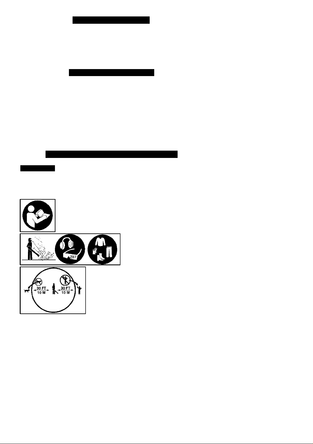
TABLE OF CONTENTS
Warranty Statement 2 Storage 13
Identification of Safety Symbols 2 Troubleshooting Table 14
Safety Rules 3 Emissions Statement 15
Assembly 5 Parts List 17
Operation 8 Spanish 20
Maintenance 11 Parts and Ordering Back Cover
WARRANTY STATEMENT
TWO YEAR FULL WARRANTY ON CRAFTSMAN® GAS BLOWER
When used and maintained according to the operator’s manual, if this product fails
due to a defect in material or workmanship within two (2) years from the date of pur
chase, return it to any Sears store, Sears Service Center, or other Craftsman outlet
in the United States for free repair (or replacement If repair proves Impossible).
This warranty excludes spark plug and air cleaner, which are expendable parts that
can wear out from normal use in less than two years.
This warranty applies for only 30 days from the date of purchase If this product is
used for commercial or rental purposes.
This warranty gives you specific legal rights, and you may also have other rights
which vary from state to state.
Sears, Roebuck and Co., Hoffman Estates, IL 60179
IDENTIFICATION OF SAFETY SYMBOLS
AwARNiNG: This unit can be dangerous! Careless or
improper use can cause serious injury.
Read your operator's manual carefully until you completely un
derstand and can follow all warnings and safety rules before
operating the unit. Failure to do so can result in serious injury.
Save operator's manual.
The blower can throw objects
violently. You can be blinded or
injured. Always wear hearing
protection and safety glasses
marked Z87. Always wear
heavy, long pants, long sleeves,
boots and gloves.
Hazard zone for thrown objects. Keep children,
bystanders, and animals away from work area a
minimum of 30 feet (10 meters) when starting or
operating unit. Do not point blower nozzle in the
direction of people or pets.
Page 3
IDENTIFICATION OF SAFETY SYMBOLS
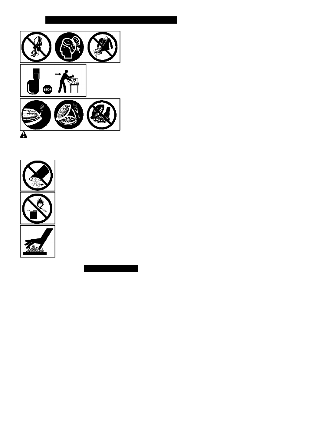
Secure hair above shoulder length.
Do not wear jewelry, loose olothing,
or clothing with loosing hanging
straps, ties, tassels, etc. They can
be caught In moving parts.
Always stop unit and disconnect spark plug
before cleaning or servicing.
WARNING; Stop the engine before opening the vacuum inlet door. The
engine must be stopped and the impeller blades no longer turning to avoid serious
injury from the rotating blades. Gently tilt the handle of the screwdriver toward the
back of the unit to release the iatch while pulling up on the vacuum inlet cover with
your other hand.
When using the vacuum attachment, the unit is designed to
pick up dry material such as leaves, grass, small twigs, and bits
of paper. Do not vacuum stones, gravel, metal, broken glass,
etc., to avoid severe damage to the impeller.
A WARNING: Fire hazard. Never mix, pour, or store gasoline
or use the unit near a flame or sparks (including smoking, open
flames, or work that can cause sparks).
A WARNING: The muffler is very hot during and after use.
Do not touch the muffler, muffler guard, or surrounding surfaces,
or allow combustible material such as dry grass or fuel to do so.
SAFETY RULES
A
WARNING; Failure to follow ail
Safety Rules and Precautions can re
sult in serious injury.
KNOW YOUR UNIT
• Read your operator’s manual care
fully until you completely understand
and can follow all warnings and
safety rules before operating the unit.
• Restrict unit to users who under
stand and will follow all warnings and
safety rules in this manual.
A WARNING: Inspect area before
starting unit. Remove all debris and
hard objects such as rocks, glass,
wire, etc. that can ricochet, be thrown,
or otherwise cause injury or damage
during operation.
Page 4

Use your unit as a bbwer for:
• Sweeping debris or grass clippings
from driveways, sidewalks, patios, etc.
• Blowing grass clippings, straw, or
leaves into piles, around joints, or be
tween bricks.
Use your unit as a vacuum for;
• Picking up dry material such as
leaves, grass, small twigs, and bits of
paper.
• For best results during vacuum use,
operate your unit at high speed.
• Move slowly back and forth over the
material as you vacuum. Avoid forc
ing the unit into a pile of debris as
this can clog the unit,
• Keep the vacuum tube about an inch
above the ground for best results.
PLAN AHEAD
• Always wear eye protection when op
erating, servicing, or performing main
tenance on unit. Wearing eye protec
tion will help to prevent rocks or debris
from being blown or ricocheting into
eyes and face which can result in
blindness and/or serious injury. Eye
protection should be marked Z87.
• Always wear foot protection. Do not
go barefoot or wear sandals.
• Always wear respirator or face mask
when working with unit in dusty envi
ronments,
• Secure hair above shoulder length.
Secure or remove jewelry, loose
clothing, or clothing with loosely
hanging straps, ties, tassels, etc.
They can be caught in moving parts,
• Do not operate unit when you are
tired, ill, upset, or if you are under the
influence of alcohol, drugs, or medi
cation.
• Keep children, bystanders, and ani
mals away from work area a mini
mum of 30 feet (10 meters) when
starting or operating unit. Do not
point blower nozzle in the direction of
people or pets.
HANDLE FUEL WITH CAUTION, IT IS
HIGHLY FLAMMABLE
• Eliminate all sources of sparks or
flame (including smoking, open
flames, or work that can cause
sparks) in the areas where fuel Is
mixed, poured, or stored,
• Mix and pour fuel in an outdoor area;
store fuel in a cool, dry, well ventilated
place; use an approved, marked con
tainer for ali fuel purposes.
• Do not smoke while handling fuel or
while operating the unit.
• Make sure the unit is properly as
sembled and in good operating con
dition.
• Do not fill fuel tank while engine is
running.
• Avoid spilling fuel or oil. Wipe up fuel
spills before starting engine.
• Move at least 10 feet (3 meters)
away from fuel and fueling site be
fore starting engine,
• Always store gasoline in a container
approved for flammable liquids,
OPERATE YOUR UNIT SAFELY
 WARNING: Stop the engine be
fore opening the vacuum Inlet door. The
engine must be stopped and the impel
ler blades no longer turning to avoid se
rious injury from ffie rotating blades.
• Inspect unit before each use for
worn, loose, missing, or damaged
parts. Do not use until unit is In
proper working order,
• Keep outside surfaces free from oil
and fuel.
• Never start or run engine inside a
closed room, building or other unventllated area. Breathing exhaust
fumes can kill.
• To avoid static electricity shock, do
not wear rubber gloves or any other
Insulated gloves while operating unit.
• Do not set unit on any surface except
a clean, hard area while engine is run
ning. Debris such as gravel, sand,
dust, grass, etc, could be picked up by
the air intake and thrown out through
discharge opening, damaging unit,
property, or causing serious Injury to
bystanders or operator.
• Avoid dangerous environments. Do
not use in unventilated areas or
where explosive vapors or carbon
monoxide build up could be present.
• Do not overreach or use from unsta
ble surfaces such as ladders, trees,
steep slopes, rooftops, etc. Keep firm
footing and balance at all times,
• Never place objects inside the
blower tubes; always direct the blow
ing debris away from people, ani
mals, glass, and solid objects such
as trees, automobiles, walls, etc. The
force of air can cause rocks, dirt, or
sticks to be thrown or to ricochet
which can hurt people or animals,
break glass, or cause other damage.
• Never run unit without the proper
equipment attached. When using
your unit as a blower, always install
Page 5

blower tubes. When using the op
tional vacuum kit, always install vac
uum tubes and vacuum bag assem
bly. Make sure vacuum bag assem
bly is completely zipped,
• Check air intake opening, blower
lubes, and vacuum tubes frequently,
always with engine stopped and
spark plug disconnected. Keep vents
and discharge tubes free of debris
which can accumulate and restrict
proper air flow.
• Never place any object in air intake
opening as this could restrict proper air
flow and cause damage to the unit.
• Never use for spreading chemicals,
fertilizers, or other substances which
may contain toxic materials.
• To avoid spreading fire, do not use
near leaf or brush fires, fireplaces,
barbecue pits, ashtrays, etc.
• Use only for jobs explained in this
manual,
MAINTAIN YOUR UNIT PROPERLY
^WARNING: Disconnect spark
piug before performing maintenance
except for carburetor adjustments.
• Have all maintenance other than the
recommended procedures described
in the operator’s manuai performed
by a Sears Service Center.
• Use only recommended Craftsman
replacement parts; use of any other
parts may void your warranty and
cause damage to your unit.
• Empty fuel tank before storing the
unit. Use up fuel left in carburetor by
starting engine and ietting it run until
it stops.
• Do not use any accessory or attach
ment other than those recommended
by manufacturer for use with your unit,
• Do not store the unit or fuel in a closed
area where fuel vapors can reach
____
sparks or an open flame from hot
water heaters, electric motors or
switches, furnaces, etc,
• Store in a dry area out of reach of
children.
SAFETY NOTICE: Exposure to vibra
tions through prolonged use of gaso
line powered hand tools could cause
blood vessel or nerve damage in the
fingers, hands, and joints of people
prone to circulation disorders or abnor
mal swelling. Prolonged use in cold
weather has been linked to blood ves
sel damage in otherwise healthy
people, if symptoms occur such as
numbness, pain, loss of strength,
change in skin color or texture, or loss
of feeling in the fingers, hands, or
joints, discontinue the use of this tool
and seek medical attention. An
anti vibration system does not guaran
tee the avoidance of these problems.
Users who operate power tools on a
continual and regular basis must moni
tor closely their physicai condition and
the condition of this tool.
SPECIAL NOTICE; This unit is
equipped with a temperature limiting
muffler and spark arresting screen
which meets the requirements of Cali
fornia Codes 4442 and 4443. All U.S.
forest land and the states of California,
Idaho, Maine, Minnesota, New Jersey,
Oregon, and Washington require by
law that many internal combustion en
gines be equipped with a spark arrest
ing screen. If you operate in a locale
where such regulations exist, you are
legally responsible for maintaining the
operating condition of these parts. Fail
ure to do so is a violation of the law.
Refer to the MAINTENANCE section for
information on maintenance of the
muffler and spark arresting screen.
ASSEMBLY
CARTON CONTENTS
Check carton contents against the fol
lowing list.
Model 358.794772
• Blower
• Upper blower tube
• Lower blower tube
• High velocity nozzle
• Elbow tube
• Vacuum bag
• Upper vacuum tube
• Lower vacuum tube
• 2-Cycle engine oil
NOTE: It is normal for the fuel filter to
rattle in the empty fuel lank.
ASSEMBLY
^WARNING: Stop engine and be
sure the impeller blades have stopped
turning before opening the vacuum in
let door or attempting to insert or re
move the vacuum tubes. The rotating
blades can cause serious injury.
Page 6
A WARNING: !f you receive your
unit assembled, repeat all steps to en
sure your unit is properly assembled
and all fasteners are secure.
• A standard screwdriver Is required
for assembly.
BLOWER ASSEMBLY
BLOWER TUBE ASSEMBLY
If you have already assembled your
unit for use as a vacuum, remove the
vacuum tubes and collection bag,
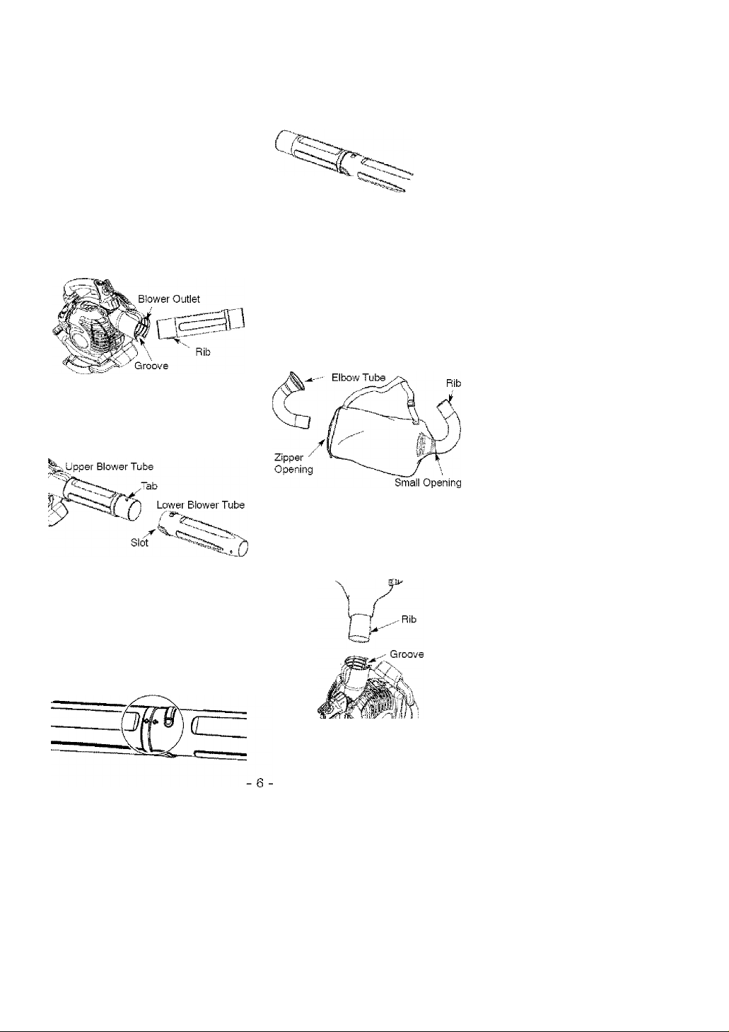
1. Align the rib on the upper blower
tube with the groove in the blower
outlet; slide the tube into place.
NOTE; Knob must be loose enough to
allow blower tube to be Inserted in
blower outlet. Loosen knob by turning
counterclockwise.
2.
Secure the tube by turning the
knob clockwise.
3.
Align the slots on the lower blower
tube with the tabs on the upper
blower tube.
6, To remove the tubes, turn the knob
counterclockwise to loosen the
tubes; remove the tubes.
HIGH-SPEED NOZZLE ASSEMBLY
When greater air speed is desired, use
the high-speed nozzle.
1, Align the slots on the nozzle with
the tabs on the lower blower tube.
High-Speed
Nozzle
Lower Blower
Tube
2.
Slide the nozzle onto the lower
blower tube.
3.
Turn the nozzle clockwise until a
click is felt to secure the nozzle to
the lower blower tube.
i)i\
VACUUM ASSEMBLY
VACUUM BAG ASSEMBLY
1, Open the zipper on the vacuum
bag and insert the elbow tube.
2, Push the small end of the elbow
tube through the small opening in
the bag.
4.5.Slide the lower blower tube onto
the upper blower tube.
Turn the lower blower tube clock
wise until a click is felt to secure
the lower blower tube to the upper
blower tube.
NOTE; When the upper and lower
blower tubes are assembled together
properly, the arrows on both tubes will
be aligned.
NOTE: Make sure edge of the small
opening is flush against the flared area
of the elbow tube, and the rib on the
elbow tube is on the bottom.
3, Close the zipper on the bag. Make
sure the zipper is closed completely.
4, Remove blower tubes from engine.
Insert the elbow tube into the blow
er outlet. Make sure elbow tube rib
is aligned with the blower outlet
groove.
Page 7

6. Turn knob clockwise to secure el
bow tube.
VACUUM TUBE ASSEMBLY
A WARNING; Stop engine and be
sure the impeller blades have stopped
turning before opening the vacuum inlet
door or attempting to insert or remove
the vacuum or blower tubes. The rotat
ing blades can cause serious injury.
1. insert the tip of a screwdriver into
the latch area of the vacuum inlet.
5, Push the upper vacuum tube into
the vacuum inlet. Turn the tube
counterclockwise until a click is felt
to secure the tube to the blower unit.
6, Align slanted end of lower vacuum
tube as shown. Firmly push lower
vacuum tube into upper vacuum
tube.
2. Gently tilt the handle of the screw
driver toward the front of the unit to
release the latch while pulling up
on the vacuum inlet cover with your
other hand.
3. Hold the vacuum inlet cover open
until upper vacuum tube is installed,
Vacuum
Inlet
4. Align the tabs on the inside of the
vacuum inlet with the slots in the
upper vacuum tube.
“ Vacuum
Slanted end of
lower vacuum tube
HOW TO CONVERT UNIT FROM
VACUUM USE TO BLOWER USE
1, Remove the elbow tube and vacu
um bag by turning the knob coun
terclockwise to loosen the elbow
tube.
2, Remove the vacuum tubes by turn
ing the tubes clockwise.
3, Close the vacuum inlet cover and
make sure it is latched closed,
4, Reinstall the blower tubes (see
BLOWER TUBE ASSEMBLY).
VACUUM BAG SHOULDER STRAP
ADJUSTMENT
1, Hold the unit as shown with the
muffler side facing away from your
body and clothes.
2, Pass the shoulder strap over your
head and onto your right shoulder.
3, Extend your left arm toward the
rear of the vacuum bag,
4, Adjust shoulder strap until the vacu
um bag/shoulder strap seam lies be
tween your thumb and index finger.
5, Make sure air flows freely from the
elbow tube into bag. If bag is
kinked, the unit will not operate
properly.
Page 8

SHOULDER STRAP ATTACHMENT
(optional accessory #71-85783)
1, Pass the shoulder strap over your
head and onto your left shoulder,
2, Snap the hook onto the retainer
(see following Illustration).
BLOWER USE
Retainer
VACUUM USE
Retainer
OPERATION
KNOW YOUR BLOWER
READ THIS OPERATOR’S MANUAL AND SAFETY RULES BEFORE OPERATING YOUR
UNIT, Compare the illustrations with your unit to familiarize yourself with the location
of the various controls and adjustments. Save this manual for future reference,
MULCHING BLADES
Your blower is equipped with mulching blades as a standard feature. When using
the vacuum attachment, the mulching blades automatically reduce debris at a
ratio of up to 16:1.
Throttle Position Lever
Upper Vacuum Tube
Elbow Tube
Throttle Trigger ^
starter
Rope
STOP Switch
Spark Plug
Upper Blower Tube
X
Fuel Mix
Fill Cap
Primer
Bulb
STOP SWITCH
The STOP switch is used to stop the
engine. To stop the engine, push and
hold the STOP switch in the STOP posi
tion until the engine stops.
Vacuum Handie
Lower Vacuum Tube
Lower Blower Tu
THROTTLE TRIGGER
The THROTTLE TRIGGER is used to se
lect the desired engine speed.
High
Speed
Nozzle
Page 9

THROTTLE POSITION LEVER
The THROTTLE POSITION LEVER is de
signed to allow setting engine speed
during blower use only. To avoid caus
ing damage to the unit, DO NOT at
tempt to use the throttle position lever
during vacuum use.
PRIMER BULB
The PRIMER BULB removes air from
the carburetor and fuel lines and fills
them with fuel. This allows you to start
the engine with fewer pulls on the
starter rope. Activate primer bulb by
pressing it and allowing it to return to
its original position.
START LEVER
The START LEVER helps to supply fuel
to the engine to aid in starting. Activate
the starting system by moving the start
lever to the START position. DO NOT
squeeze the throttle trigger until the
engine has started and runs. After the
engine starts, allow the engine to
warm-up 10-15 seconds, then fully
squeeze the throttle trigger to deacti
vate the starting system (start lever re
turns to RUN position).
OPERATING TIPS
• While vacuuming or blowing debris,
hold the unit with the muffler side fac
ing away from your body and clothes
(see OPERATING POSITION below).
• To reduce the risk of hearing loss
associated with sound level(s), hear
ing protection is required,
• To reduce the risk of injury associated
with contacting rotating parts, stop the
engine before installing or removing
attachments. Do not operate without
guard(s) in place.
• Operate power equipment only at rea
sonable hours-not early in the morn
ing or iate at night when people might
be disturbed. Comply with times listed
in local ordinances. Usual recommen
dations are 9:00 a.m. to 5:00 p.m.,
Monday though Saturday,
• To reduce noise levels, limit the num
ber of pieces of equipment used at
any one time,
• To reduce noise levels, operate pow
er blowers at the lowest possible
throttle speed to do the job.
• Use rakes and brooms to loosen
debris before blowing.
• In dusty conditions, slightly dampen
surfaces or use a mister attachment
when water is available.
• Conserve water by using power blow
ers instead of hoses for many lawn
and garden applications, including
areas such as gutters, screens, patios,
grills, porches, and gardens.
• Watch out for children, pets, open
windows, or freshly washed cars.
Blow debris away safely,
• Use the full blower nozzle extension
so the air stream can work close to
the ground.
• After using blowers and other equip
ment, CLEAN UPl Dispose of debris
in trash receptacles.
OPERATING POSITION
BEFORE STARTING ENGINE
^WARNING: Be sure to read the
fuel information in the safety rules
before you begin. If you do not
understand the safety rules, do not
attempt to fuel your unit. Cali
1 -800-235-5878.
FUELING ENGINE
^WARNING: Remove fuel cap
slowly when refueling.
This engine is certified to operate on un
leaded gasoline. Before operation, gaso
line must be mixed with a good quality
synthetic 2-cycle air-cooled engine oil.
Vife recommend Craftsman brand syn
thetic oil. Mix gasoline and oil at a ratio
of 40:1. A 40:1 ratio is obtained by mix
ing 3.2 ounces of oil with 1 gallon of un
Page 10

leaded gasoline, included with this blow
er is a 3.2 ounce container of oil. Pour
the entire contents of this container into
1 gallon of gasoline to achieve the prop
er fuel mixture. DO NOT USE automotive
oil or boat oil. These oils will cause en
gine damage. When mixing fuel, follow
instructions printed on container. Once
oil is added to gasoline, shake container
momentarily to assure that the fuel is
thoroughly mixed. Always read and fol
low the safety rules relating to fuel be
fore fueling your unit.
IMPORTANT
Experience indicates that alcohol
blended fuels (called gasohol or using
ethanol or methanol) can attract mois
ture which ieads to separation and
formation of acids during storage.
Acidic gas can damage the fuel sys
tem of an engine while in storage.
To avoid engine problems, empty the
fuel system before storage for 30 days
or longer. Drain the gas tank, start the
engine and let it run until the fuel lines
and carburetor are empty. Use fresh
fuel next season. Never use engine or
carburetor cleaner products in the fuel
tank or permanent damage may occur.
Fuel stabilizer is an acceptable alter
native in minimizing the formation of
fuel gum deposits during storage.
Craftsman brand oil is already blended
with fuel stabilizer. See the STORAGE
section for additional information.
HOW TO STOP YOUR ENGINE
• Release the throttle trigger.
• Push and hold the STOP switch in the
STOP position until the engine stops,
HOW TO START YOUR ENGINE
A WARNING: You MUST make sure
the tubes are secure before using the
unit.
• Fuel engine. Move at least 10 feet (3
meters) away from the fueling site,
• Hold the unit in the starting position
as shown. Make sure the blower end
Is directed away from people, ani
mals, glass, and solid objects.
^WARNING: When starting engine,
hold the unit as illustrated. Do not set
unit on any surface except a clean, hard
area when starting engine or while en
gine is running. Debris such as gravel,
sand, dust, grass, etc. could be picked
up by the air intake and thrown out
through the discharge opening, damag
ing the unit or property, or causing seri
ous injury to bystanders or the operator.
STARTING A COLD ENGINE (or
warm engine after running out of fuel)
1, Move the throttle position lever
(cruise control) to the idle position.
Throttle
Position
Lever
(Cruise
Control)
2, Slowiy press the primer bulb 6 times.
3. Move the start lever to the START
position.
10
Page 11

system. You do not have to pull the
starter rope handle sharply or
briskly. Pull starter rope handle 5
times with a controlled and steady
motion (no more than 3 times
above 90°F). If engine starts and
runs prior to 5 pulls, allow engine to
run for 5 seconds; then, fully
squeeze the throttle trigger to dis
engage the starting system (start
lever returns to RUN position).
Steps 5 and 6 are not necessary.
Fully squeeze the throttle trigger to
5.
disengage the starting system (start
lever returns to RUN position).
6, Puli starter rope handle with a con
trolled and steady motion while
squeezing throttle trigger until
engine starts and runs.
STARTING A WARM ENGINE
1. Squeeze and hold the throttfe trigger.
2, Pull starter rope handle with a con
trolled and steady motion while
squeezing throttle trigger until en
gine starts and runs.
NOTE: Normally, the warm starting
prooedure can be used within 5-10
minutes after the unit is turned off. If
the unit sits for more than 10 minutes
without being used, it will be necessary
to start the unit by following the steps
under STARTING A COLD ENGINE or fol
lowing the starting instruction steps
shown on the unit.
STARTING A FLOODED ENGINE
Flooded engines can be started by mov
ing the start lever to the RUN position
and fully squeezing the throttle trigger.
Pull the starter handle repeatedly while
squeezing throttle trigger until engine
starts and runs. This could require pull
ing the starter handle many times, de
pending on how badly the unit is
flooded. If the unit still doesn't start, re
fer to the TROUBLESHOOTING TABLE or
call 1-800-235-5878,
MAINTENANCE
CUSTOMER RESPONSIBILITIES
A WARNING: Disconnect the spark plug before performing maintenance,
service, or adjustments.
CARE & MAINTENANCE TASK WHEN TO PERFORM
Check for loose fasteners and parts Before each use
Check for damaged or worn parts Before each use
Inspect and clean unit and labels After each use
Clean air filter Every 5 hours of operation
Replace spark plug Yearly
Replace fuel filter Yearly
Check muffler mounting screws Yearly
Ay
I WARNING; Avoid touching muf
fler unless engine and muffler are cold,
A hot muffler can cause serious burns.
Ay
I WARNING; Stop engine and be
sure the impeller blades have stopped
turning before opening the vacuum in
let door or attempting to insert or re
move the vacuum or blower tubes.
The rotating blades can cause serious
injury. Always disconnect the spark
plug before performing maintenance or
accessing movable parts.
GENERALRECOMMENDATIONS
The warranty on this unit does not cov
er items that have been subjected to
operator abuse or negligence. To re
ceive full value from the warranty, the
operator must maintain unit as instruct
ed in this manual. Various adjustments
will need to be made periodically to
properly maintain your unit.
11
Page 12

CHECK FOR LOOSE
FASTENERS AND PARTS
• Muffler
• Spark Plug Boot
• Air Filter
• Housing Screws
CHECK FOR DAMAGED OR
WORN PARTS
Contact Sears Service Center for re
placement of damaged or worn parts.
• Fuel Tank - Do not use unit if fuel tank
shows signs of damage or leaks.
• Vacuum Bag - Do not use vacuum
bag if it is tom or damaged,
INSPECT AND CLEAN UNIT
AND LABELS
• After each use, inspect complete unit
for loose or damaged parts. Clean
the unit using a damp doth with a
mild detergent.
• Wipe off unit with a clean dry cloth.
CLEAN AIR FILTER
A dirty air filter decreases engine per
formance and increases fuel consump
tion and harmful emissions. Always
clean after every 5 hours of operation.
REPLACE SPARK PLUG
Replace spark plug each year to ensure
the engine starts easier and runs better.
Set spark plug gap at 0.025 inch. Igni
tion timing is fixed, nonadjustable.
1, Twist, then pull off spark plug boot.
2, Remove spark plug from cylinder
and discard.
3, Replace with Champion RCJ-6Y
spark plug and tighten securely
with a 3/4 inch socket wrench.
4, Reinstall the spark plug boot,
REPLACE FUEL FILTER
To replace fuel filter, drain unit by run
ning it dry of fuel, then remove fuel
cap/retainer assembly from tank. Pull
filter from tank and remove it from the
fuel line. Install new fuel filter on fuel
line; reinstal! parts.
CHECK MUFFLER MOUNTING
SCREWS
Once each year, ensure muffler
mounting screws are secure and tight
ened properly to prevent damage.
Cleaning the air filter:
1. Clean the cover and the area
around it to keep debris from falling
into the carburetor chamber when
the cover is removed.
NOTE; Move start lever to RUN posi
tion before opening air filter cover.
2. Open air filter cover by pushing
button (see illustration). Remove
air filter.
NOTE; Do not clean filter in gasoline
or other fiammabie solvent. Doing so
can create a fire hazard or produce
harmful evaporative emissions.
3. Wash the filter in soap and water.
4. Allow filter to dry,
5. Apply a few drops of oil to the filter;
squeeze filter to distribute oil.
6. Replace parts.
INSPECT MUFFLER AND SPARK
ARRESTING SCREEN
^ WARNING; The muffler on this
product contains chemicals known to
the State of California to cause cancer.
As the unit is used, carbon deposits
build up on the muffler and spark ar
resting screen, and must be removed
to avoid creating a fire hazard or af
fecting engine performance.
12
Page 13

Replace the spark arresting screen ev
ery 50 hours of operation or if any dam
age or breaks in the screen are noted.
NOTE; Do not attempt to clean the
spark arresting screen.
1. Remove 3 screws from muffler cov
er. Remove muffler cover.
Loosen and remove 4 screws from
the muffler hood.
Remove the muffler hood and spark
arresting screen.
Install new spark arresting screen.
Reinstall muffler hood and 4
sorews. Tighten screws securely.
Reinstall muffler cover and 3
sorews. Tighten seourely.
NOTE; If any part of the muffler is
cracked, broken or damaged, we rec
ommend that the muffler be replaced.
CARBURETOR ADJUSTMENT
The carburetor has been carefully set
at the factory. Adjustments may be
necessary if you notice any of the fol
lowing conditions;
• Engine will not idle when the throttle is
released.
Idle Speed Adjustment
Allow engine to idle. Adjust speed until
engine runs without stalling (idle speed
too slow).
• Turn idle speed screw clockwise to
increase engine speed if engine
stalls or dies.
• Turn idle speed screw counterclock
wise to deorease engine speed.
If you require further assistance or are
unsure about performing this proce
dure, contact your Sears Service Cen
ter or call our customer assistance
help line at 1-800-235-5878.
STORAGE
A WARNING; Perform the following
steps after each use:
• Allow engine to cool, and secure the
unit before storing or transporting.
• Store unit and fuel in a well venti
lated area where fuel vapors cannot
reach sparks or open flames from
water heaters, electric motors or
switches, furnaces, etc.
• Store unit with all guards in place.
Position unit so that any sharp object
cannot accidentally cause injury.
• Store unit and fuel well out of the
reach of children.
SEASONAL STORAGE
Prepare unit for storage at end of sea
son or if it will not be used for 30 days
or more. If your unit is to be stored for
a period of time:
• Clean the entire unit before lengthy
storage.
• Store in a clean dry area,
• Lightly oil external metal surfaces.
FUEL SYSTEM
Empty the fuel system before storage for
30 days or longer. Drain the gas tank,
start the engine and let it run until the
tuel lines and carburetor are empty. Use
fresh fuel next season. Under FUELING
ENGINE in the OPERATION section of this
manual, see message labeled
IMPORTANT regarding the use of gasohoi in your engine.
Fuel stabilizer is an acceptable alterna
tive in minimizing the formation of fuel
gum deposits during storage. Add stabi
lizer to gasoline in fuel tank or fuel stor
age container. Follow the mix instruc
tions found on stabilizer container. Run
engine at least 3 minutes after adding
stabilizer.
Craftsman 40:1,2-cycle engine oil (air
cooled) is already blended with fuel
stabilizer. If you do not use this Sears
oil, you can add a fuel stabilizer to your
fuel tank.
13
Page 14

ENGINE
• Remove spark plug and pour 1 tea
spoon of 40:1,2-cycle engine oil (air
cooled) through the spark plug open
ing. Slowly puli the starter rope 8 to
10 times to distribute oil,
• Replace spark plug with new one of
recommended type and heat range.
• Clean air filter.
TROUBLESHOOTING TABLE
• Check entire unit for loose screws,
nuts, and bolts. Replace any dam
aged, broken, or worn parts,
• At the beginning of the next season,
use only fresh fuel having the proper
gasoline to oil ratio.
OTHER
• Do not store gasoline from one sea
son to another.
• Replace your gasoline can if it starts
to rust.
A WARNING: Always stop unit and disconnect sparkplug before perform
ing any of the recommended remedies below otherthan remedies that re
quire operation of the unit.
TROUBLE CAUSE REMEDY
Engine will not
start.
Engine will not
idle properly.
Engine will not
accelerate,
lacks power, or
dies under a
load.
Engine smokes
excessively.
Engine runs hot.
1. Engine flooded.
2. Fuel tank empty,
3. Spark plug not firing.
4. Fuel not reaching
carburetor.
5. Compression low.
1. Fuel not reaching
carburetor.
2. Carburetor requires
adjustment.
3. Crankshaft seals worn.
4. Compression low.
1. Air filter dirty.
2. Fuel not reaching
carburetor.
3. Spark plug fouled.
4. Carburetor requires
adjustment.
5. Carbon build up.
6. Compression low.
1, Choke partially on.
2. Fuel mixture incorrect.
3. Air filter dirty.
4, Carburetor requires
adjustment.
1, Fuel mixture incorrect.
2, Spark plug incorrect.
3, Carburetor requires
adjustment.
4- Carbon build up.
1, See “Starting a Flooded Engine"
in Operation section.
2, Fill tank with correct fuel mixture.
3- Install new spark plug.
4, Check for dirty fuel filter; replace.
Check for kinked or spilt fuel line;
repair or replace.
5, Contact Sears Service (see back cover).
1, Check for dirty fuel filter; replace.
Check for kinked or spilt fuel line;
repair or replace.
2- Contact Sears Service (see back cover).
3, Contact Sears Service (see back cover).
4, Contact Sears Service (see back cover).
1. Clean or replace air filter.
2. Check for dirty fuel filter; replace.
Check for kinked or split fuel line;
repair or replace.
3. Clean or replace spark plug
and re-gap.
4. Contact Sears Service (see back cover).
5. Contact Sears Service (see back cover).
6. Contact Sears Service (see back cover).
1, Adjust choke.
2, Empty fuel tank and refill with
correct fuel mixture.
3, Clean or replace air filter.
4, Contact Sears Service (see back cover).
1. See “Fueling Engine” in Operation
section.
2. Replace with correct spark plug.
3. Contact Sears Service (see back cover).
4. Contact Sears Service (see back cover).
14
Page 15

U.S. EPA/CALIFORNIA
EMISSION CONTROL WARRANTY STATEMENT
YOUR WARRANTY RiGHTS AND OB
LiGATIONS; The U.S. Environmental
Protection Agency/California Air Re
sources Board and Sears, Roebuck and
Co., U.S.A., are pleased to explain the
emissions control system warranty on
your year 2007 and later small off-road
engine. In California, all small off-road
engines must be designed, built, and
equipped to meet the State's stringent
anti-smog standards. Sears must war
rant the emission control system on your
small off-road engine for the periods of
time listed below provided there has
been no abuse, neglect, or improper
maintenance of your small off-road en
gine. Your emission control system in
cludes parts such as the carburetor, the
ignition system and the fuel tank (Califor
nia only). Where a warrantable condition
exists. Sears will repair your small off
road engine engine at no cost to you.
Expenses covered under warranty in
clude diagnosis, parts and labor.
MANUFACTURER'S WARRANTY
COVERAGE: If any emissions related
part on your engine (as listed under
Emissions Control Warranty Parts List) is
defective or a defect in the materials or
workmanship of the engine causes the
failure of such an emission related part,
the part will be repaired or replaced by
OWNER’S WARRANTY RESPONSIBI
LITIES; As the small off-road engine
engine owner, you are responsible for
the performance of the required mainte
nance listed in your operator's manual.
Sears recommends that you retain all
receipts covering maintenance on your
small off-road engine, but Sears cannot
deny warranty solely for the lack of re
ceipts or for your failure to ensure the
performance of all scheduled mainte
nance. As the small off-road engine en
gine owner, you should be aware that
Sears may deny you warranty coverage
if your small off-road engine engine or a
part of it has failed due to abuse, ne
glect, improper maintenance, unap
proved modifications, or the use of parts
not made or approved by the original
equipment manufacturer. You are re
sponsible for presenting your small off
road engine to a Sears authorized repair
center as soon as a problem exists.
Warranty repairs should be completed in
a reasonable amount of time, not to ex
ceed 30 days, if you have any ques
tions regarding your warranty rights and
responsibilities, you should contact your
nearest authorized service center or call
Sears at 1-800-469-4663. WARRANTY
COMMENCEMENT DATE: The warran
ty period begins on the date the small
off-road engine is purchased. LENGTH
OF COVERAGE: This warranty shall be
for a period of two years from the initial
date of purchase. WHAT IS COV
ERED: REPAIR OR REPLACEMENT
OF PARTS. Repair or replacement of
any warranted part will be performed at
no charge to the owner at an approved
Sears Service Center, if you have any
questions regarding your warranty rights
and responsibilities, you should contact
your nearest authorized service center
or call Sears at 1-800-469-4663. WAR
RANTY PERIOD: Any warranted part
which is not scheduled for replacement
as required maintenance, or which is
scheduled only for regular inspection to
the effect of “repair or replace as neces
sary” shall be warranted for 2 years. Any
warranted part which is scheduled for
replacement as required maintenance
shall be warranted for the period of time
up to the first scheduled replacement
point for that part.
owner shall not be charged for diagnos
tic labor which leads to the determina
tion that a warranted part is defective if
the diagnostic work is performed at an
approved Sears Service Center. CON
SEQUENTIAL DAMAGES: Sears may
be liable for damages to other engine
components caused by the failure of a
warranted part sill under warranty.
WHAT IS NOT COVERED:
caused by abuse, neglect, or improper
maintenance are not covered. ADD-ON
OR MODIFIED PARTS: The use of
add-on or modified parts can be
grounds for disaiiowing a warranty claim.
Sears is not liable to cover failures of
warranted parts caused by the use of
add-on or modified parts.
FILE A CLAIM: If you have any ques
tions regarding your warranty rights and
responsibilities, you should contact your
nearest authorized service center or call
Sears at 1 -800-469-4663,
DIAGNOSIS: The
Ail failures
HOW TO
15
Page 16

WHERE TO GET WARRANTY SER
VICE: Warranty services or repairs shaii
be provided at all Sears Service Cen
ters. Cai! 1-800-469-4663.
MAINTENANCE, REPLACEMENT
AND REPAIR OF EMISSION RE
LATED PARTS: Any Sears approved
replacement part used in tbe perfor
mance of any warranty maintenance or
EMISSION CONTROL WARRANTY
PARTS LIST: Carburetor, Ignition Sys
tem: Spark Plug (covered up to mainte
nance schedule), ignition Module, Muf
fler including Catalyst, Fuel Tank (Cali
fornia only). MAINTENANCE STATE
MENT: The owner is responsible for the
performance of all required maintenance
as defined in the operator’s manual.
repair on emission related parts will be
provided without charge to the owner if
the part is under warranty.
The information on the product iabei indicates which standard your engine is certified.
Exampfe: (Year) EPA Phase 1 or Phase 2 and/or CALIFORNIA.
___________
IMPORTANT EMISSIOti INFORMATIOH
THIS ENGINE CONFORMS TO EKH. AND EVAP.
EMISSIONS REGULATIONS POR SMALL OFF
F/MLÏ.fflSP.
SERIAL#
MODEL#
THE LOWER THE AIR INDEX, THE LESS POLLUTION
REFER TO OWNER'S MANUAL FOR MAINTENANCE
ROAD ENGINES
THE AIR INDEX OF THIS ENGINE IS3
4 I el i tel
SreCIFICATiONS AND ADJUSTMENTS.
This engine Is certified to be emissions compliant for the following use:
la Moderate (50 hours)
□ Intermediate (125 hours)
l~l Extended (300 hours)
16
Page 17

REPAIR PARTS
SEARS GAS BLOWER MODEL 358.794772
^WARNING
Af! repairs, adjustments and
maintenance not described in
the Operators Manual must be
performed by Qualified Service
Personnel,
Ref. Part No. Description R«f. Part No. Description
1. 530015814 Screw
2. 545150502 Assy - Engine Cover
3. 530015880 Screw
4. 545134001 Shield - Baffle
5. 545099101 Baffle
6. 545052401 Hub
7. 545052501
S. 545050407 Kit -Starter Pulley (Incl. 6.7)
9. 545054901 Spiing - Starter
10. 545152901 Handle - Starter
11. 545050416 Kit - Rope
12. 545107101 Tube - Staster l ope
13. 545138601 Handle - RH
14. 5450S1830 Kit - Switch (Incl. 15)
15. 54512S201 Pi'otectar - Switch
IS. 545137701 Grommet
17. 545099001 Bearing
IS. 545116201
19. 530015814 Screw
20. 545111501 Rächet - Cruise Control
21. 545173101 Washer - Wave
22. 5450S1867 Kit - Cruise cantro1(lncl.19.20.21)
23. 545144901 Trigger - Throltie
24. 545138801 Handle - LH
25.
530016406
26.
530015814
27. 545139001 Door - Vac
2S. 545115601 Spring - Vac door
545144501
29.
30. 530015940 Screw - Handle vac
31. 545152501 Assy - Scroll LH (Incl. 27.28)
32. 545120701 Blade - Mulch
33. 545113601 Assy - Impeller
34. 545113701 Spacer - Flywheel
35. 530015197 Nut - Blower Knob
Spring - Pulley
Screw
Knob - Blower tube
36, 530016386 Screw
37, 545161608 Assy -Scroll RH (Incl, 17)
38, 545138501 Handle - Vac
39, 545100401 Assy - Fuel tank
40, 530095646 Assy - Fuel Pickup
41, 530069247 Kit - Fuel line (carb/purge)
42, 530069216 Kit - Fuel line ftank/purqe)
43. 530057973 Assy - Fuel Cap with retainer
44, 530016445 Screw - Fuel tank retainer
ilncl. 40.41.42.43)
Not Shown
545167641
545001245 Decal - Warning
545042802 Decal - Start Instruction
Page 18

REPAIR PARTS
SEARS GAS BLOWER MODEL 358.794772
Rei. Part No. Description
1. 545090001 Assy - Muffler (ind. 2,3.4,5)
2. 530015241 Screw
3. 5450S1S45 Kit - Spark Screen
4. 53005S9S2 Boll - Muffier
5. 5450S1S32 Gasket - Muffler (gasket kit)
6. 545115301 Cylinder
7. 530015953 Bolt
8. Champion Spark plug iRCJ-5Y)
9. 545034901 Adapter - Carb.
10. 545115501 Linkage - Throttle
11. 545031357 Kit - Carb. Assy (C1U-W43B)
12. 545157104 Lever - Choke
13. 545139301 Base - Airbox
14. 530016429 Screw
15. 545146501 Filter
16. 545139201 Cover - Air box filter
17. 530053709 Bulb - Purge
18. 545031332 O-ring (Carb/Adapter)(gasket kit)
19. 530016441 Screw
20. 545031332 O-Ring (Adapter/Cyl.)(gasket kit)
21. 545031364 Kit - Piston/Connecting Rod
22. 530012472 Ring - Piston
23. 530015162 Retainer - Wrist Pin
24. 545031365 Kit - Assy Connecting Rod
25. 545153001 Module - Ignition
26. 530016357 Screw
27. 545127601 Assy - Wire Harness
28. 545031332 O-ring seal - Crankcase (kit)
29. 530015323 Washer
30. 530054115 Assy - Flywheel
31. 530015941 Retainer -Crankshaft
32. 530055723 Bearing - Outer
33. 530019264 Seal
(Ind. 12.17)
(Incl. 22.23.24)
Ret. Part No. Description
34. 530032125 Bearing - Inner
35. 530012582 Assy - Crankcase
36. 545102102 Assy - Crankcase/Crankshaft
37. 545081832 0 - Ring (Rear plug)(gasket kit)
33. 530057954 Assy - Rear Plug (Incl. 37)
39. 530016386 Sciew
40. 545081832 Kit - Gasket (Incl. 5.18.20.28.37)
iincl, 32,33,34)
iinci, 31,35)
Page 19

REPAIR PARTS
SEARS GAS BLOWER MODEL 358.794772
Ref. Part No. Description
1. 545099401 Tube - Upper vac
2. 530095539 Tube - Lower vac
3. 545139501 Tube - J
4. 530095564 Assy - Vac bag
5. 545138001 Tube - Upper Slower
6 . 545138101 Tube - Lower Slower
7. 545151201 Nozzle - High Speed
 Loading...