

Page 1
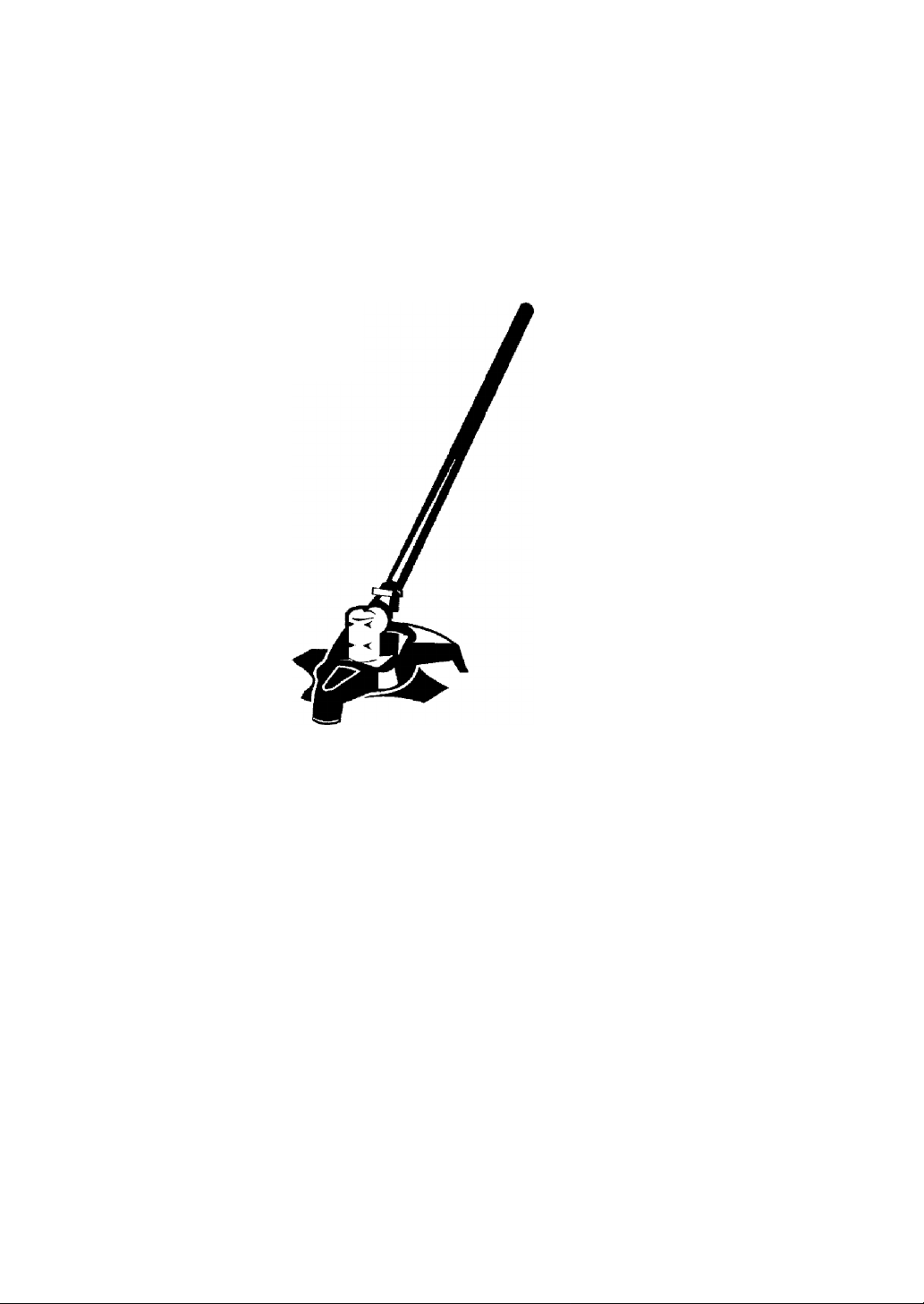
Operator’s Manual
CRRFTSMRN
BRUSHCUTTER ATTACHMENT
Model No.
358.792443
NOT DESIGNED FOR USE
WITH ELECTRIC POWERHEADS
Safety
Assembly
Operation
Maintenance
Parts List
Español, p. 17
DANGER:
Read and follow all Safety Rules and Operating
Instructions before first use of this product.
For answers to your questions about this product: Call 7
9
am-7 pm, Mon.-Sat, or 10 am-7 pm. Sun.
1 ^00-235-5878 (Hours listed are Centra! Time)
Sears, Roebuck and Co., Hoffman Estates, IL 60179 U.S.A.
530164972 9/12/06
Page 2
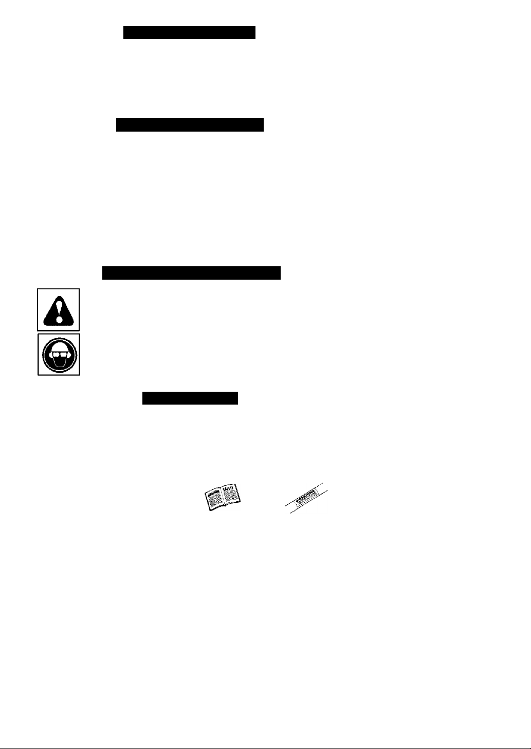
TABLE OF CONTENTS
Warranty Statement 2 Service & Adjustments 14
Identification of Symbols 2
Safety Rules
Assembly
Operation 10
Maintenance 14 Parts and Ordering Back Cover
Storage 15
2
Parts List 16
5
Spanish 17
WARRANTY STATEMENT
ONE YEAR FULL WARRANTY ON CRAFTSMAN® BRUSHCUTTER ATTACHMENT
When used and maintained according to the operator's manual, if this product fails
due to a defect in material or workmanship within one year from the date of pur
chase, return it to any Sears store, Sears Service Center, or other Craftsman outlet in
the United States for free repair {or replacement if repair proves impossible).
This warranty excludes expendable parts that can wear out from normal use in
less than one year.
This warranty applies for only 30 days from purchase date if this product is used
for commercial or rental purposes.
This warranty gives you specific legal rights, and you may also have other rights
which vary from state to state.
Sears, Roebuck and Co., Hoffman Estates, IL 60179
IDENTIFICATION OF SYMBOLS
DANGER! This brushcutter
can be dangerous! Careless or
improper use can cause
serious or even fatal injury.
Always wear appropriate ear protection, eye protection and bead protection,
SAFETY RULES
 WARNING; When using garden
ing appliances, basic safety precau
tions should always be followed to re
duce the risk of fire and serious injury.
Read and follow all instructions. Fail
ure to do so can result in serious injury.
A DANGER: This power tool can be
dangerous! This unit can cause seri
ous injury including amputation or
blindness to the operator and others.
The warnings and safety instructions
in this manual must be followed to pro
vide reasonable safety and efficiency
in using the unit. The operator is re
sponsible for following the warnings
Read and understand the
operator's manual before
using the brushcutter.
and instructions in this manual and on
the unit. Read the entire operator’s
manual before assembling and using
the uniti Restrict the use of this unit to
persons who read, understand, and
follow the warnings and instructions in
this manual and on the unit. Never al
low children to operate this unit.
OPERATOR'S
MANUAL
 DANGER:
vices.
SAFETY INFORMATION
ON THE UNiT
Never use flailing de-
Page 3
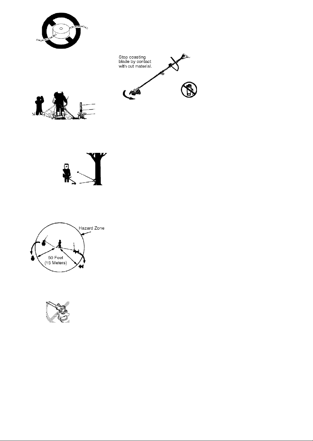
a DANGER: Blade can thrust vio
lently away from material it does not
cut. Blade thrust can cause amputa
tion of arms or legs. Keep people and
animals 50 feet (15 meters) away.
a.
^WARNING: Blade/trimmer line
can throw objects violently. You can be
blinded or injured. Wear eye and leg
protection.
ALWAYS WEAR:
Eye
Protection
Leg
Guards
Boots
^WARNING; Hazard zone for
thrown objects. Biade/trimmer line can
throw objects violently. Others can be
blinded or injured. Keep people and
animals 50 feet (15 meters) away.
^WARNING: Do not use trimmer
head as a fastening device for the
blade.
Thrown
objects
iS
a WARNING; The blade continues
to spin after throttle is released or engine
is turned off. The coasting blade can
throw objects or seriously cut you if acci
dentally touched. Stop the blade by con
tacting the left hand side of coasting
blade with material already cut.
OPERATOR SAFETY
• Dress properly. Always wear safety
glasses or similar eye protection
when operating, or performing main
tenance on your unit (safety glasses
are available). Eye protection should
be marked Z87.
• Always wear face or dust mask if op
eration is dusty.
• Always wear heavy, long pants, long
sleeves, boots, and gloves. Wearing
safety leg guards is recommended.
• Always wear foot protection. Do not
go barefoot or wear sandals. Stay
clear of spinning line/blade.
• Secure hair above shoulder length.
Secure or remove loose clothing and
jewelry or clothing with loosely hang
ing ties, straps, tassels, etc. They
can be caught in moving parts,
• Being fully covered also helps pro
tect you from debris and pieces of
toxic plants thrown by spinning line/
blade.
• Stay Alert. Do not operate unit when
you are tired. Hi, upset or under influ
ence of alcohol, drugs, or medica
tion, Watch what you are doing; use
common sense.
• Wear hearing protection.
• Never start or run the engine inside a
closed room or building. Breathing
exhaust fumes can kill.
• Keep handles free of oil and fuel.
• Always use the handlebar and a
properly adjusted shoulder strap
when using brushcutter attachment
(see ASSEMBLY).
UNIT/MAINTENANCE SAFETY
^WARNING; Disconnect powerhead spark plug (or disconnect powerhead from power source) before per
forming maintenance.
Page 4

• Look for and roplacG damaged or
loose parts before each use. Look
for and repair fuel leaks before use.
Keep unit in good working condition,
• Throw away blades that are bent,
warped, cracked, broken, or dam
aged in any other way. Replace trim
mer head parts that are cracked,
chipped, broken, or damaged in any
other way before using the unit.
• Maintain the unit according to recom
mended procedures. Keep the biade
sharp. Never use flailing devices,
wire, rope, string, etc.
• Use only specified blade or trimmer
head; make sure it is properly in
stalled and securely fastened.
• Never start engine with clutch shroud
removed. The clutch can fly off and
cause serious injury.
• Be sure blade or trimmer head stops
turning when engine idles.
• Make carburetor adjustments with the
lower end supported to prevent the
blade or trimmer line from contacting
any object. Hold the unit by hand; do
not use the shoulder strap for support.
• Keep others away when making car
buretor adjustments.
• Use only recommended Craftsman
accessories and replacement parts.
• Have all maintenance and service
not explained in this manual per
formed by a Sears Service Center.
FUEL SAFETY
• Mix and pour fuel outdoors.
• Keep away from sparks or flames.
• Use a container approved for fuel.
• Do not smoke or allow smoking near
fuel or the unit or while using the unit.
• Avoid spilling fuel or oil. Wipe up all
fuel spills before starting engine.
• Move at least 10 feet (3 meters) away
from fueling site before starting engine.
• Stop engine and allow it to cool be
fore removing fuel cap.
• Remove fuel cap slowly,
CUTTING SAFETY
A WARNING: Inspect the area to be
cut before each use. Remove objects
(rocks, broken glass, nails, wire, string,
etc.) which can be thrown or become
entangled in the blade or trimmer line.
• Keep others including children, ani
mals, bystanders, and helpers at
least 50 feet {15 meters) away. Stop
the engine immediately if you are ap
proached.
• Always keep engine on the righthand side of your body.
• Hold the unit firmly with both hands.
• Keep firm footing and balance. Do
not overreach.
• Keep blade/trimmer head below
waist level.
• Do not raise powerhead engine above
your waist.
• Keep all parts of your body away
from spinning blade/line and muffler.
• Cut from your left to your right. Cut
ting on right side of shield will throw
debris away from the operator.
• Use only in daylight or good artificial
light.
• Use only for jobs explained in this
manual.
TRANSPORTING AND STORAGE
• Stop the powerhead engine before
carrying unit.
• Keep muffler away from your body.
• Allow engine to cool and secure unit
before storing or transporting it in a
vehicle.
• Empty the fuel tank before storing or
transporting the unit. Use up fuel left
in the carburetor by starting the en
gine and letting it run until it stops.
• Store unit and fuel in an area where
fuel vapors cannot reach sparks or
open flames from water heaters,
electric motors or switches, furnaces,
etc.
• Store unit so the blade or line limiter
blade on shield cannot accidentally
cause injury.
• Store unit indoors, out of reach of
children.
SPECIAL NOTICE: Exposure to vibra
tions through prolonged use of gaso
line powered hand tools could cause
blood vessel or nerve damage in the
fingers, hands, and joints of people
prone to circulation disorders or abnor
mal swellings. Prolonged use in cold
weather has been linked to blood ves
sel damage in otherwise healthy
people. If symptoms occur such as
numbness, pain, loss of strength,
change in skin color or texture, or loss
of feeling in the fingers, hands, or
joints, discontinue the use of this tool
and seek medical attention. An anfivibration system does not guarantee
the avoidance of these problems.
Users who operate power tools on a
continual and regular basis must moni
tor closely their physical condition and
the condition of this tool.
SAVE THESE INSTRUCTIONS
Page 5
ASSEMBLY
CARTON CONTENTS
Check carton contents against the fol
lowing list.
Model 358.792443
• Brushcutter attachment
• Handlebar
• Handlebar mounting bracket for 1''
{2.5 cm) shaft
• Handlebar mounting bracket for 7/8"
(2.2 cm) shaft
• Bracket cover (2)
• Shoulder strap
• Upper shoulder strap clamp
• Lower shoulder strap clamp (with
spacer tabs)
• Handlebar bracket screws (4)
• Shoulder strap clamp screws (2)
• 4-point weed blade (assembled on
brushcutter attachment)
• Large nut for installing blade
• Retaining washer
• Cupped washer
• Metal shield (assembled on brush
cutter attachment)
• Trimmer head
• Plastic shield
• Wing nut (screwed onto plastic shield)
• Attachment Hanger
• Hex Wrench
• Container of line
Examine parts for damage. Do not use
damaged parts.
NOTE; if you need assistance or find
that parts are missing or damaged, call
1-800-235-5878.
ASSEMBLY
^WARNING: If received assembled,
repeat all steps to ensure your unit is
properly assembled and all fasteners
are secure.
• A hex wrench (provided) is required
for assembly.
INSTALLING BRUSHCUTTER AT
TACHMENT
CAUTION: When removing or instal
ling attachments, place the unit on a
flat surface for stability.
1. Loosen the coupler by turning the
knob counterclockwise.
Coupler
LOOSEN
TIGHTEN
2.
Remove the shaft cap from the
brushcutter attachment (if present).
Position locking/release button of
attachment into guide recess of
coupler.
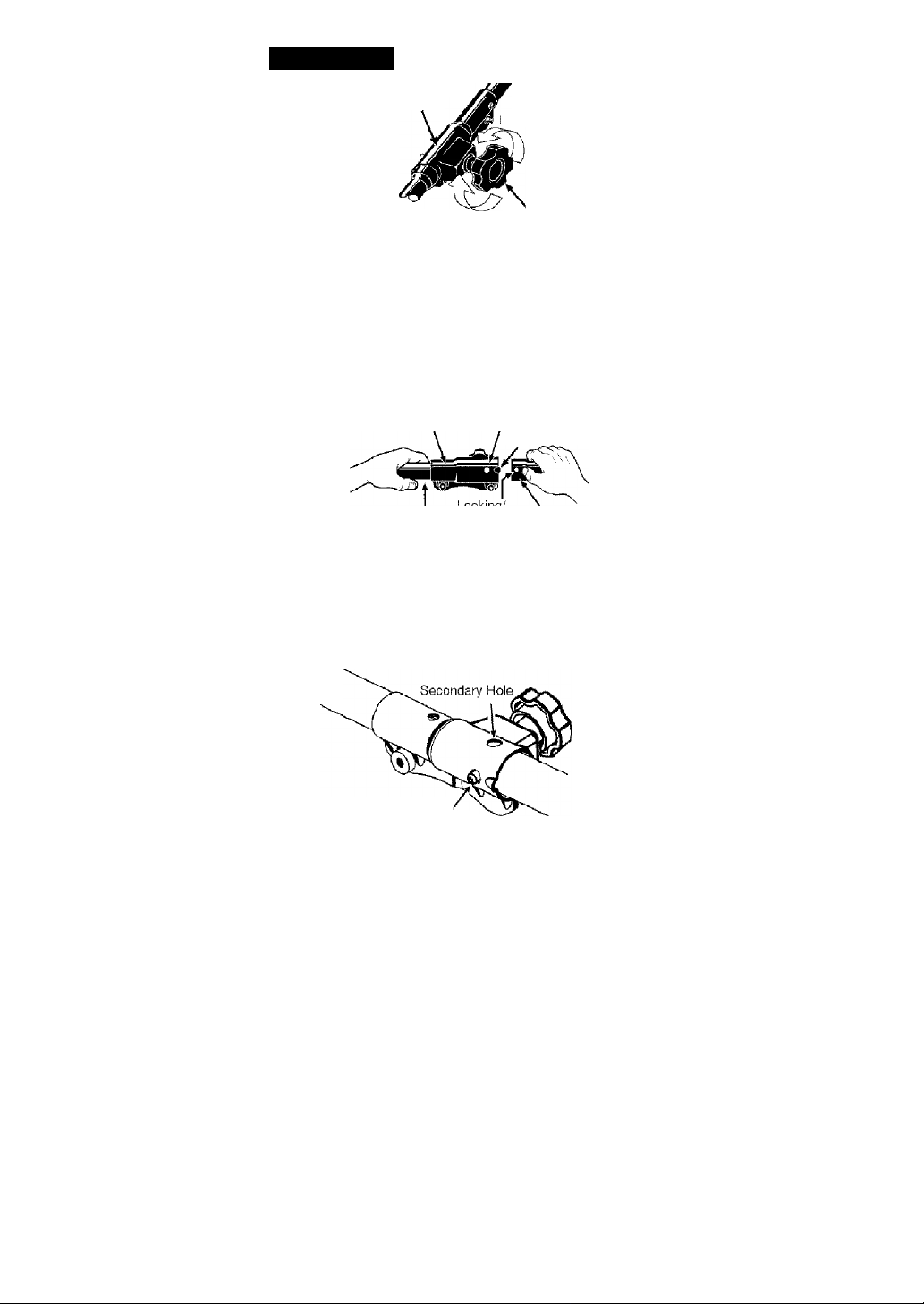
4.
Push the attachment into the cou
pler until the locking/release button
snaps into the primary hole.
5.
Before using the unit, tighten the
knob securely by turning clock
wise.
Coupler Primary Hole
Uooer Looking/
Release
Knob
Guide Recess
Attachment
Button
a WARNING: Make sure the lock
ing/release button is locked in the pri
mary hole and the knob is securely
tightened before operating the unit. Us
ing the wrong hole could lead to serious
injury or damage to the unit.
Locking/Reiease ,
Button in Primary Hole
Page 6
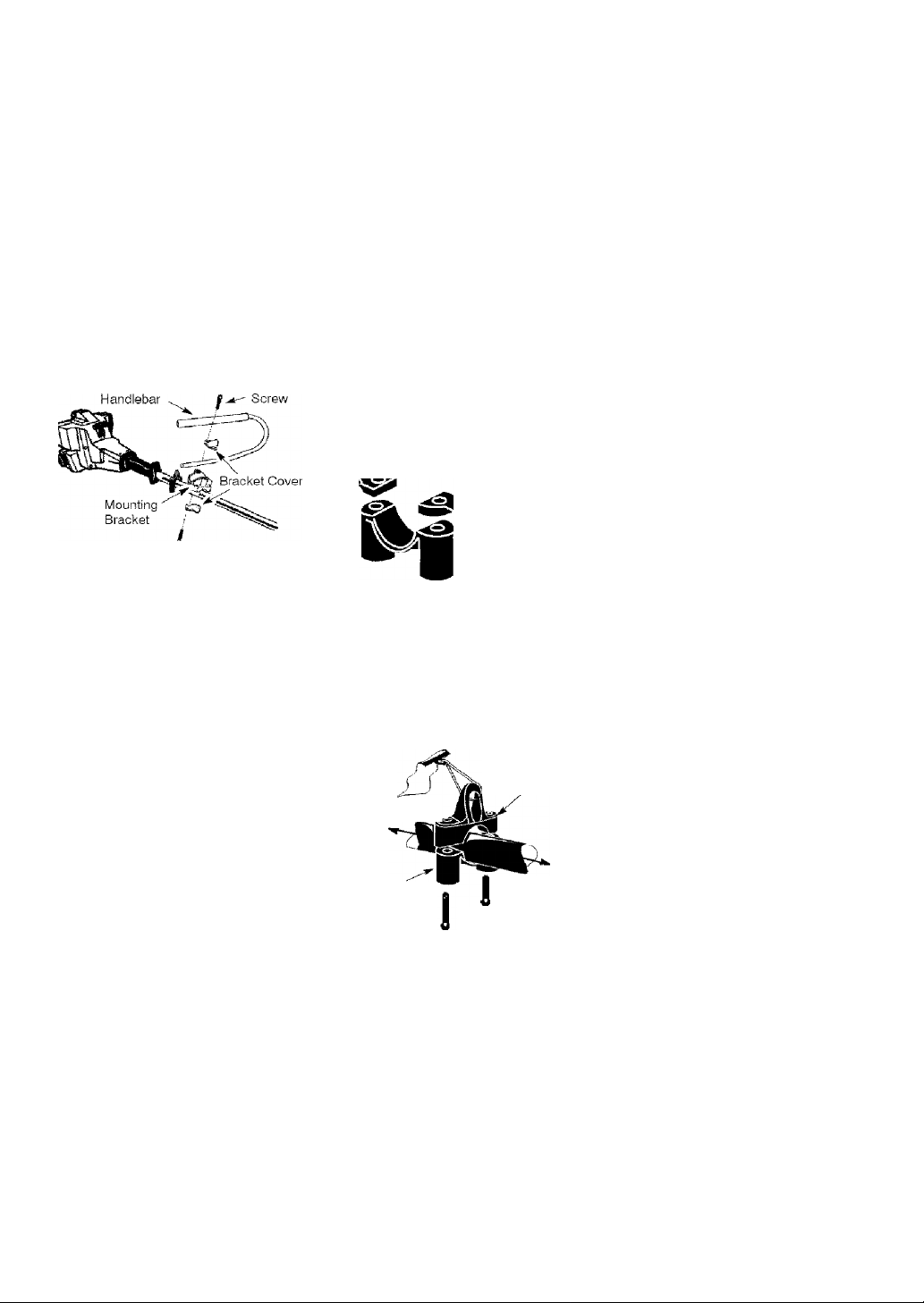
HANDLEBAR ASSEMBLY
A DANGER: RISK OF CUT. To avoid
serious injury, the barrier portion of the
handlebar must be installed as shown
on the upper shaft of the powerhead to
provide a barrier between operator and
the spinning blade. Attach handlebar
mounting bracket above arrow on
safety warning decal on the upper
shaft (powerhead end of unit). Ensure
handlebar is positioned on mounting
bracket at the end of the arrow on the
handlebar decal.
NOTE: Two mounting brackets are in
cluded with this attachment. Both brack
ets are provided to adapt this attach
ment for use with powerheads that have
either a 1" {2.5 cm) diameter or a 7/8"
(2.2 cm) diameter upper shaft. The cor
rect bracket must be used to ensure that
the handlebar is mounted securely to
the upper shaft before use.
1. Place the mounting bracket over
the upper shaft above the arrow on
the safety label. Be sure to use
the correct mounting bracket for
either the 1" (2.5 cm) or 7/8" (2.2
cm) diameter upper shaft.
2. Position one of the bracket covers
under the upper shaft and align the
mounting bracket and the bracket
cover screw holes. Insert two
screws into the screw holes.
3. Secure the mounting bracket by
tightening the screws with the hex
wrench.
4. Locate the decal on the handlebar.
This decal includes an arrow. Posi
tion the handlebar with the mount
ing bracket at the end of the arrow.
5. Position the second bracket cover
over the handlebar. Align the
mounting bracket and the bracket
cover screw holes. Again make
sure the handlebar is at the end of
the arrow.
6. Insert two screws and hand tighten
only. Be sure the handlebar is
installed correctly; then, tighten each
screw securely with the hex wrench.
SHOULDER STRAP ASSEMBLY
^WARNING; Proper shoulder
strap and handlebar adjustments must
be made with the engine completely
stopped before using unit. The shoul
der strap clamp must be installed as
shown above the handlebar on the up
per shaft (powerhead end of unit).
NOTE: The lower shoulder strap clamp
has two spacer tabs attached. These
tabs are provided to adapt this attach
ment for use with powerheads that have
a 1" diameter upper shaft (the shoulder
strap clamp will not tighten down se
curely on the 1" diameter upper shaft
without using these spacer tabs). The
tabs must be broken off completely be
fore use and placed over the screw
holes on the lower shoulder strap clamp.
These tabs are not needed for power-
heads with a 7/8" upper shaft.
LOWER SHOULDER STRAP
CLAMP
Spacer Tabs
-----
Spacer Tabs
positioned for use
on 1" diameter
upper shaft
1. Place the upper shoulder strap
clamp over the upper shaft above
the handlebar.
2. Position the lower shoulder strap
clamp under the upper shaft and
align the upper and lower clamp
screw holes (use spacer tabs be
tween upper and lower clamps if
necessary to secure damp, i.e. for
1" diameter upper shaft).
Upper Shoulder
Strap Clamp
POWERHEAD
END
Lower Shoulder
Strap Clamp
3. Insert two screws into the screw
holes.
ATTACHMENT
END
Screws
Page 7
4. Secure shoulder Strap clamp by
tightening screws with the hex
wrench.
5. insert your right arm and head
through the shouider strap and ailow it to rest on your left shouider.
Make sure the danger sign is on
your back and the hook is to the
right side of your waist.
NOTE; A one-half twist is buiit in the
shoulder strap to allow the strap to rest
flat on the shoulder.
6. Adjust the strap, allowing the hook
to be about 6 inches below the
waist.
7. Fasten the strap hook to the clamp
and lift the tool to the operating
position.
8. Try on shoulder strap and adjust
for fit and balance before starting
the engine or beginning a cutting
operation.
NOTE; It may be necessary to relo
cate the shoulder strap clamp on the
shaft for proper balancing of unit.
HARNESS
ADJUSTMENT
FOR BALANCE
diameter. To assemble your unit, go to
the section for the desired configuration
and follow the instructions.
ASSEMBLY INFORMATION TRIMMER HEAD
NOTE; Remove the blade and metal
shield before attaching the plastic shield
and trimmer head. To remove blade,
align hole in the dust cup with the hole
in the side of the gearbox by rotating
the blade. Insert a small screwdriver
into aligned holes. This will keep the
shaft from turning while loosening the
blade nut. Remove blade nut by turning
clockwise. Remove the screwdriver.
Remove both washers and blade.
To remove metal shield, loosen and re
move the four mounting screws. See AT
TACHING THE METAL SHIELD and
INSTALLATION OF THE METAL BLADE for
illustrations. Be sure to store all parts
and instructions for future use.
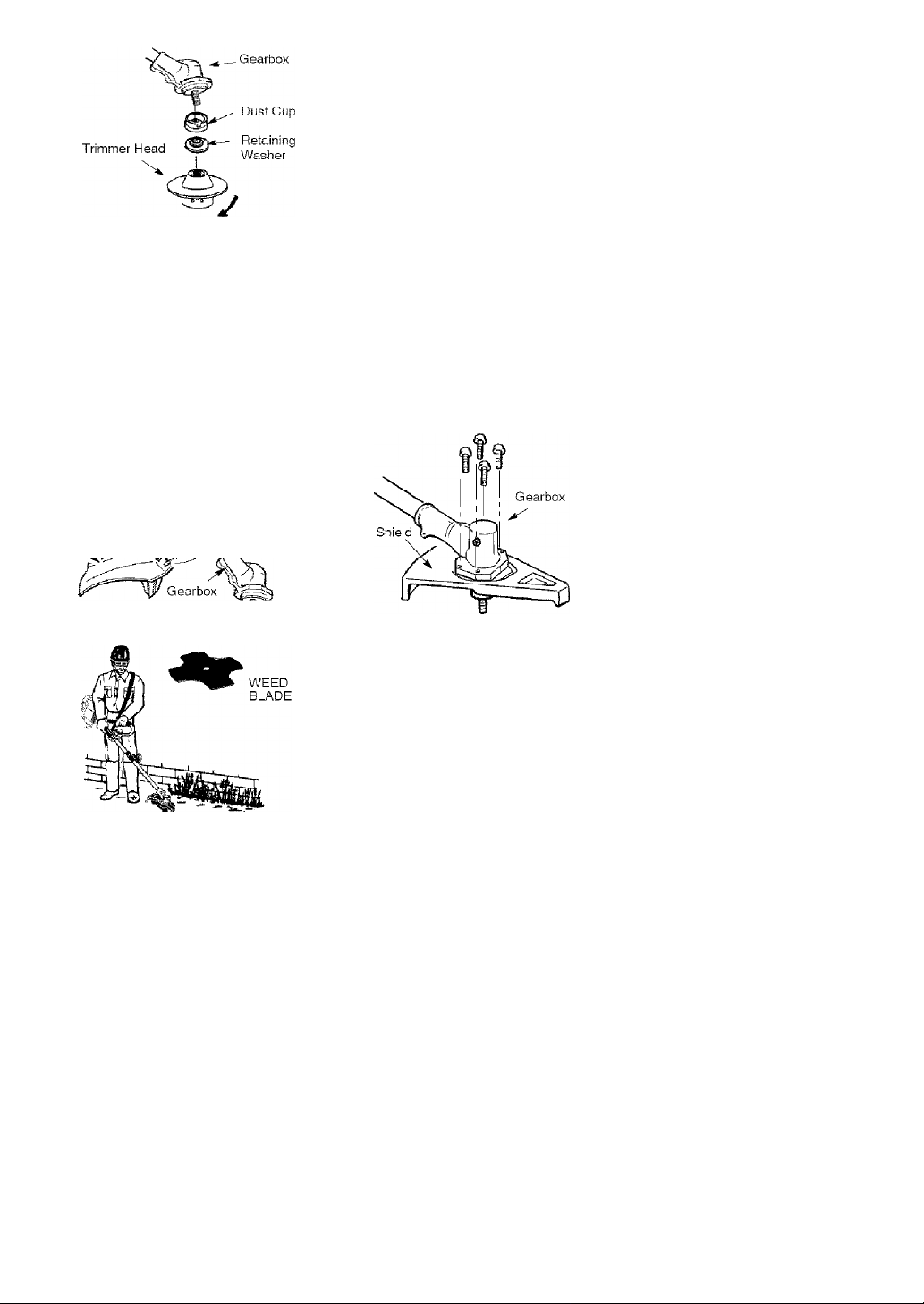
INSTALLATION OF THE TRIMMER
HEAD
NOTE; Before installing the trimmer
head, make sure the dust cup and re
taining washer are positioned on the
shaft of the gearbox. The retaining
washer must be positioned with the
raised section toward the gearbox.
1.
Align hole in the dust cup with the
hole in the side of the gearbox by
rotating the dust cup.
2.
Insert a small screwdriver into
aligned holes. This will keep the
shaft from turning while tightening
trimmer head.
CONFIGURING YOUR UNIT
You can configure your unit using a trim
mer head for grass and light weeds, or a
weed blade for cutting grass, weeds,
and brush up to f/2 inch (1 cm) in
While holding the screwdriver in
position, thread trimmer head onto
the shaft by turning counterclock
Only tighten hand tight!
wise.
Page 8
4. Remove the screwdriver
ATTACHING THE PLASTIC SHIELD
^WARNING: The shield must be
properly installed. The shield provides
partial protection from the risk of
thrown objects to the operator and oth
ers and is equipped with a line limiter
blade which cuts excess line to the
proper length. The line iimiter biade
(on underside of shield) is sharp and
can cut you.
1. Remove wing nut from shield.
2. insert bracket into slot on shield.
3. Pivot shield until bolt passes
through hole in bracket.
4. Tighten the wing nut securely.
Bracket ,
Slot \ k\ /X
Shield
Wing Nut
clockwise. Remove the screwdriver.
To remove the plastic shield, loosen and
remove wing nut. Pivot shield to release
bracket from slot. See INSTALLATION OF
THE TRIMMER HEAD and ATTACHING
THE PLASTIC SHIELD for illustrations. Be
sure to store all parts and instructions for
future use. Never use the trimmer head
with the metal blade instailed.
ATTACHING THE METAL SHIELD
^WARNING: The metal shield
must be properly installed on the tool
anytime the tool is used with a blade.
The forward tip of the metal shield
helps to reduce the occurrence of
blade thrust which can cause serious
injury such as amputation to the opera
tor or bystanders. Failure to instail the
shield in the position shown can result
in serious injury to the operator. The
length of the shield must be aligned
with the length of the shaft.
1. Place the metai shield under the
gearbox, and align the screw holes.
ASSEMBLY INFORMATION - WEED
BLADE
NOTE; Remove the trimmer head and
plastic shield before attaching the metal
shield and installing the weed biade. To
remove the trimmer head, align hole in
the dust cup with the hoie in the side of
the gearbox by rotating the dust cup.
Insert a small screwdriver into aligned
holes. This will keep the shaft from turn
ing while loosening the trimmer head.
Remove the trimmer head by turning
2. Insert and thread the 4 mounting
screws through the holes of the
gearbox and the metal shield.
Tighten evenly and secureiy with
the hex wrench provided.
INSTALLATION OF THE METAL
BLADE
^WARNING; Wear protective
gloves when handling or performing
maintenance on the blade to avoid in
jury. The blade is sharp and can cut
you even when it is not moving.
^WARNING: Do not use any
blades, or fastening hardware other than
the washers and nuts shown in the fol
lowing iilustrations. These parts must be
provided by Sears and installed as
shown below. Failure to use proper parts
can cause the blade to fly off and seri
ously hurt you or others.
8
Page 9
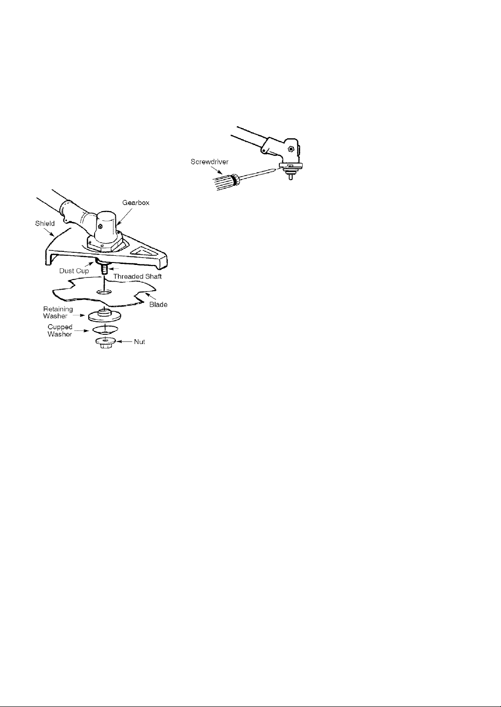
NOTE; The dust cup and retaining
washer are located on the gearbox shaft
and not in the parts bag. Al! other fas
teners mentioned in the following as
sembly steps are in the parts bag.
1. Remove the retaining washer from
the threaded shaft of the gearbox.
Leave the dust cup on the shaft.
2. Install the blade and the retaining
washer over the threaded shaft.
3. Make sure the raised part of the re
taining washer is facing the gearbox
and the raised area fits into the hole
in the center of the blade.
4. Slide the blade and retaining washer
onto the shaft of the gearbox.
5. Place the cupped washer onto the
shaft. Make sure the cupped side
of the washer is toward the blade.
6. install the blade nut by threading
onto the shaft counterclockwise.
NOTE: Make sure ail parts are in place
as illustrated, and the blade is sand
wiched between the dust cup and the
retaining washer. There should be no
space between the blade and the dust
cup or the retaining washer.
7. Align hole in dust cup with hole in
side of gearbox by rotating the
blade.
8. Insert a small screwdriver into
aligned holes. This will keep the
shaft from turning while tightening
the blade nut.
9. Tighten blade nut firmly with a
wrench while holding screwdriver
in position.
10. Remove the screwdriver.
11. Turn blade by hand. If the blade
binds against the shield, or appears
to be uneven, the blade Is not cen
tered, and you must reinstall.
NOTE: To remove blade, insert screw
driver into aligned holes. Unthread the
nut and remove parts. Be sure to store
parts and instructions for future use.
Page 10
OPERATION
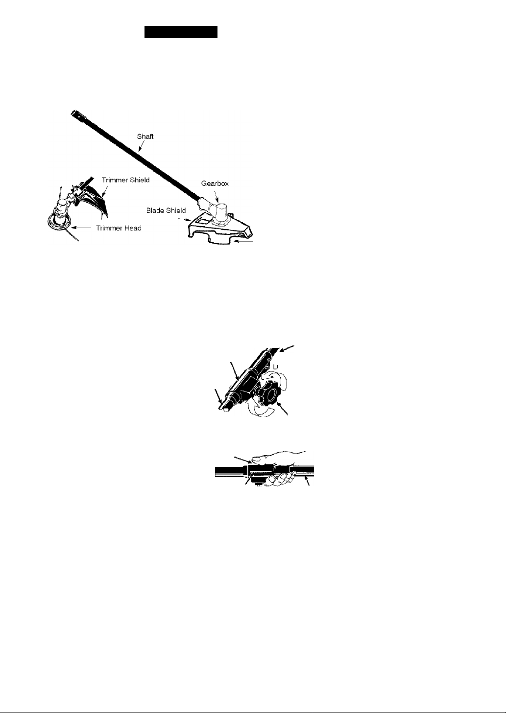
KNOW YOUR BRUSHCUTTER ATTACHMENT
READ THIS OPERATOR'S MANUAL AND SAFETY RULES BEFORE OPERATING YOUR
BRUSHCUTTER ATTACHMENT. Compare the illustrations with your unit to familiarize
yourself with the location of various controls and adjustments. Save this manual for
future reference.
Hanger
Blade
BLADE
The BLADE is designed for cutting
grass, weeds, and brush up to 1/2 inch
{1 cm) in diameter,
TRIMMER HEAD
The TRIMMER HEAD holds cutting line
and is designed for cutting grass and
light weeds.
OPERATING THE COUPLER
Your powerhead is equipped with a
coupler which enables optional attach
ments to be installed. The optional at
tachments are:
Edger................................... 71-79240
Cultivator
.............................
Blower
...
Pruner
^WARNING: Always disconnect
powerhead spark plug before remov
ing or installing attachments.
............. ..............
................................
71-79241
71-79242
71-79245
REMOVING BRUSHCUTTER AT
TACHMENT (OR OTHER OPTIONAL
ATTACHMENTS)
CAUTION: When removing or instal
ling attachments, place the powerhead
and attachment on a flat surface for
stability.
1. Loosen the coupler by turning the
knob counterclockwise.
BLADE SHIELD
The BLADE SHIELD provides protection
from the spinning blade.
TRIMMER SHIELD
The TRIMMER SHIELD provides protec
tion from the spinning trimmer head.
Upper Shaft
Coupler
DOSEN
Attachment
TIGHTEN Knob
2. Press and hold the locking/release
button.
Locking/Release
Button
^ Coupler
Attachment
3. While securely holding the upper
shaft, pull the attachment straight
out of the coupler.
Upper Shaft
10
Page 11

INSTALLING OPTIONAL ATTACH
MENT
1. Remove the shaft cap from the at
tachment {if present) and discard.
2. Position locking/release button of
attachment into guide recess of
upper shaft coupler.
3. Push the attachment into the cou
pler until the locking/release button
snaps into the primary hole.
4. Before using the unit, tighten the
knob securely by turning clockwise.
Coupler Primary Hole
Upper Locking/ Attachment
Shaft
/ Guide Recess
Button
^WARNING; Make sure the lock
ing/release button is locked in the pri
mary hole and the knob is securely
tightened before operating the unit. Us
ing the wrong hole could lead to serious
injury or damage to the unit.
INSTALLING ATTACHMENT
HANGER
An attachment hanger is provided for
storage when attachment is not in use.
To install hanger on attachment:
1. Remove the shaft cap from the at
tachment (if present) and discard.
2. Press and hold the locking/release
button.
3. Push hanger onto the attachment
until the locking/release button
snaps into the hole.
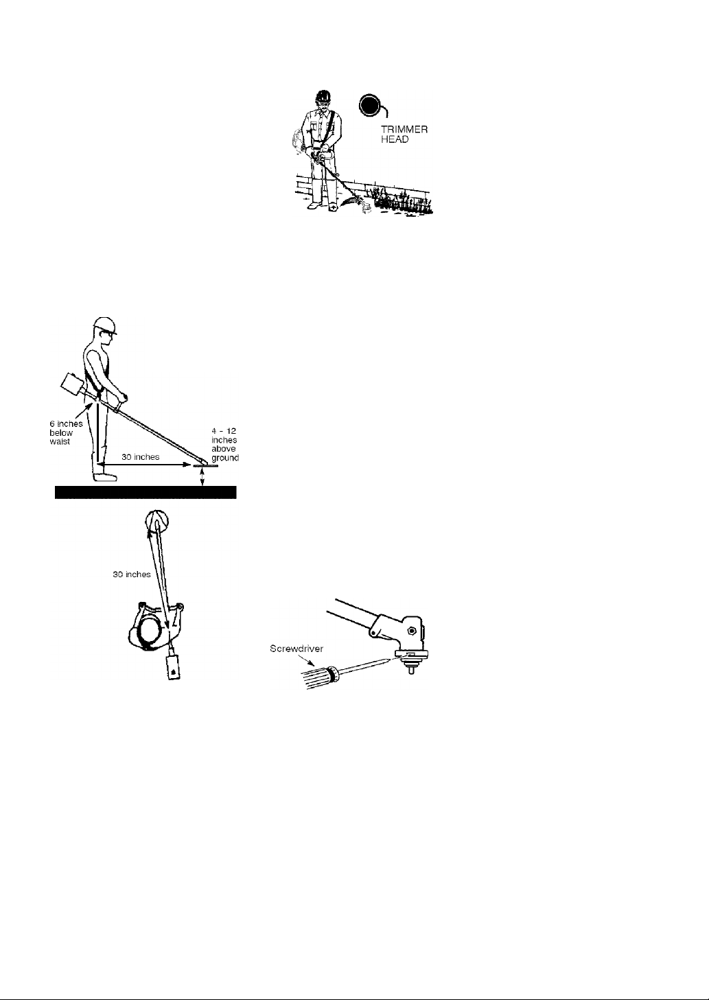
OPERATING POSITION
NOTE: This brushcutter attachment is
not designed for use with electric powerheads.
When operating unit with brushcutter
attachment, clip shoulder strap onto
upper shoulder strap clamp, stand as
shown and check for the following:
• Wear eye protection and heavy
clothing.
• Keep arms extended with right hand
holding the trigger handle of powerhead.
• Keep left arm extended with left hand
holding the handlebar.
• Keep unit below waist level.
• Shoulder strap pad should be cen
tered on your left shoulder and dan
ger sign centered on your back.
• Maintain full weight of tool on left
shoulder.
• Without bending over, keep the blade
near and parallel to the ground and
not crowded into material being cut.
OPERATING INSTRUCTIONS FOR
USE OF BRUSHCUTTER ATTACH
MENT WITH TRIMMER HEAD
^WARNING; Always wear eye
protection. Never lean over the trimmer
head. Rocks or debris can ricochet or
be thrown into eyes and face and
cause blindness or other serious injury.
Before trimming, bring engine to a
speed sufficient to cut material to be
trimmed.
Do not run the engine at a higher speed
than necessary. The cutting line will cut
efficiently when the engine is run at less
than full throttle. At lower speeds, there
is less engine noise and vibration. Al
ways release the throttle trigger and
allow the engine to return to idle speed
when not cutting.
CUTTING METHODS
^WARNING; Use minimum speed
and do not crowd the line when cutting
around hard objects (rock, gravel,
fence posts, etc.), which can damage
the trimmer head, become entangled
in the line, or be thrown causing a seri
ous hazard.
• The tip of the line does the cutting.
You will achieve the best perform
ance and minimum line wear by not
crowding the line into the cutting
area. The right and wrong ways are
shown below.
11
Page 12

Tip of line does the Line crowded into
• The line will easily remove grass and
weeds from around walls, fences,
trees and flower beds, but it also can
cut the tender bark of trees or shrubs
and scar fences.
• For trimming or scalping, use less
than full throttle to increase line life
and decrease head wear, especially:
• During light duty cutting.
• Near objects around which the line
can wrap such as small posts,
trees or fence wire.
• For mowing or sweeping, use full
throttle for a good clean job.
TRIMMING - Hold the bottom of the
trimmer head about 3 inches (8 cm)
above the ground and at an angle. Allow
only the tip of the line to make contact.
Do not force trimmer line into work
area.
SCALPING - The scalping technique
removes unwanted vegetation down to
the ground. Hold the bottom of the
trimmer head about 3 inches {8 cm)
above the ground and at an angle. Al
low the tip of the line to strike the
ground around trees, posts, monu
ments, etc. This technique increases
line wear.
MOWING - Your trimmer is idea! for
mowing in places conventional lawn
mowers cannot reach. In the mowing
position, keep the line parallel to the
ground. Avoid pressing the head into
the ground as this can scalp the
ground and damage the tool.
SWEEPING - The fanning action of the
rotating line can be used to blow away
loose debris from an area. Keep the line
parallel to and above the area surface
and swing the too! from side to side.
OPERATING INSTRUCTIONS FOR
USE OF BRUSHCUTTER ATTACH
MENT WITH WEED BLADE
• Blade Thrust is a reaction that only
occurs when using a bladed unit. This
reaction can cause serious injury such
as amputation. Carefully study this
section. It is important that you under
stand what causes blade thrust, how
you can reduce the chance of its oc
curring, and how you can remain in
control of unit if blade thrust occurs.
• WHAT CAUSES BLADE THRUST -
Blade Thrust can occur when spin
ning blade contacts an object that it
does not cut. This contact causes
blade to stop for an instant and then
suddenly move or “thrust” away from
object that was hit. The “thrusting” re
action can be violent enough to cause
operator to be propelled in any direc
tion and lose control of unit. The un
controlled unit can cause serious injury
if blade contacts operator or others.
• WHEN BLADE THRUST OCCURS
- Blade Thrust can occur without
warning if the blade snags, stalls, or
binds. This is more likely to occur in
12
Page 13

areas where it is difficult to see the
material being cut. By using the unit
properfy, the occurrence of blade
thrust will be reduced and the opera
tor will be less likely to lose control.
Cut only grass, weeds, and woody
brush up to 1/2 inch (1 cm) in diameter
with weed blade. Do not let blade con
tact material it cannot cut such as
stumps, rocks, fences, metal, etc., or
clusters of hard, woody brush with a
diameter greater than 1/2 inch (1 cm).
Use a sharp blade. A dull blade is
more likely to snag and thrust.
Cut only at full throttle. The blade will
have maximum cutting power and is
less likely to bind or stall.
“Feed” the blade deliberately and not
too rapidly. The blade can thrust
away if it is fed too rapidly.
Cut only from your left to your right.
Cutting on right side of the shield will
throw debris away from the operator.
Use the shoulder strap and keep a
firm grip on the unit with both hands.
A properly adjusted shoulder strap
will support the weight of the unit,
freeing your arms and hands to con
trol and guide the cutting motion.
Keep feet comfortably spread apart
and braced for a possible sudden,
rapid thrust of unit. Do not overreach.
Keep firm footing and balance.
Keep blade below waist level. It will
be easier to maintain control of unit.
Do not raise the engine above your
waist as the blade can come danger
ously close to your body.
Do not swing the unit with such force
that you are in danger of losing your
balance.
Bring the powerhead engine to cutting
speed before entering the material to
be cut.
if the blade does not turn when you
squeeze the throttle trigger of the pow
erhead, make sure the attachment is
fully inserted into the coupler.
Always release the throttle trigger and
allow powerhead engine to return to
idle speed when not cutting. The blade
should not turn while the engine is run
ning at idle. If the blade turns at idle,
do not use your unit. Refer to the CAR
BURETOR ADJUSTMENT section of the
powerhead manual or contact your
Sears Service Center.
• Maintain good firm footing while us
ing the unit. Do this by planting feet
firmly in a comfortable apart position.
• Cut while swinging the upper part of
your body from left to right.
• As you move forward to the next
area to cut, be sure to maintain your
balance, and footing.
RECOMMENDED CUTTING POSITION
Cut using the 2 t )
o'clock to 4 o'clock
position of the
blade
Mm WARNING: The operator or oth
ers must not try to clear away cut ma
terial with the engine running or the
. ^ 2 o'clock
4 o'clock
blade turning to avoid serious injury.
Stop engine and blade before remov
ing materials wrapped around blade or
shaft.
13
Page 14

MAINTENANCE
MAINTENANCE SCHEDULE
A WARNING: Always stop unit and disconnect spark plug wire before
performing maintenance.
CARE AND MAINTENANCE TASK
Check for loose fasteners and parts Before each use
Check for damaged or worn parts Before each use
Inspect and clean unit and decals After each use
Check or replace blade Every 5 hours of operation
GENERALRECOMMENDATIONS
The warranty on this attachment does
not cover items that have been sub
jected to operator abuse or negli
gence. To receive fuii value from the
warranty, the operator must maintain
the brushcutter attachment as instruct
ed in this manual.
CHECK FOR DAMAGED OR
WORN PARTS
Contact Sears Service Center for re
placement of damaged or worn parts,
• Blade Shield - Discontinue use of
brushcutter attachment if shield is
damaged.
• CHECK FOR LOOSE
FASTENERS AND PARTS
• Blade nut
• Fasteners
INSPECT AND CLEAN UNIT
AND DECALS
• After each use, inspect complete unit
for loose or damaged parts. Clean
the unit and decals using a damp
cloth with a mild detergent.
WHEN TO PERFORM
• Wipe off unit with a clean dry cloth.
BLADE MAINTENANCE
A WARNING: The blade will contin
ue to spin after the engine stops or af
ter the throttle trigger has been re
leased. To avoid serious injury, make
sure the blade has stopped coasting
and disconnect the spark plug before
performing work on the blade.
^WARNING: Always replace a
blade that is bent, warped, cracked,
broken, or damaged in any other way.
Never attempt to straighten and reuse
a damaged blade. Use only specified
replacement blade. Wear protective
gloves when handling or performing
maintenance on the blade to help
avoid injury.
• Check blade for flatness periodically.
Lay the blade on a flat surface to in
spect for flatness. Throw away a
blade that is not flat.
SERVICE AND ADJUSTMENTS
LINE REPLACEMENT
• Always use Craftsman replacement
line.
Choose the line size best suited for the
job at hand. Red line is designed for
cutting grass and small weeds. The
black colored line is designed for cut
ting larger weeds and light brush.
NOTE: Before inserting new line into
the holes in the cutting head, identify
the proper holes. Follow directions as
shown on the line glide plate.
1. Remove the old line and line glide
plate from the cutting head.
2. Clean entire surface of cutting
head.
3. Reinstall line glide plate (see il
lustration). Align arrow with:
when using medium (red) or
©
large (black) line
when using lines with diameter
(B) smaller than medium (red) line
(optional)
/
Trimmer head
14
Page 15

NOTE: Line glide plate must be rein-
stalied in cutting head before inserting
new line.
4. insert both ends of your line
through the proper holes in the
side of the cutting head.
Pull the line and make sure the
line is against the hub and ex
tended full through the positioning
tunnels.
Positioning ■ ieSSii
Tunnel
Line against
■^^the hub
STORAGE
a WARNING: Perform the following
steps after each use:
• Allow attachment and gearbox to
cool before storing or transporting.
• Store attachment with blade shield in
place. Position attachment so that
any sharp object cannot accidentally
cause injury.
• Store the attachment in a dry, well
ventilated area out of the reach of
children.
SEASCNAL STCRAGE
Prepare attachment for storage at end
of season or if it will not be used for 30
days or more.
If your brushcutter attachment is to be
stored for a period of time:
6. Correctly installed line wili be the
same iength on both ends.
REPLACING THE CUTTING HEAD
1. Align hole in the dust cup with the
hole in the side of the gearbox by
rotating the dust cup.
2. Insert a small screwdriver into
aligned holes. This will keep the
shaft from turning while removing
and installing trimmer head.
3.
While holding the screwdriver in
position, remove trimmer head by
turning clockwise.
4.
Thread replacement trimmer head
onto the shaft by turning counterclock
wise. Cniy tighten hand tight!
Remove the screwdriver.
5.
BLADE REPLACEMENT
Refer to the ASSEMBLY section for
blade replacement instructions and il
lustrations.
Clean the entire attachment.
Inspect the blade shield area and
clean any dirt, grass, leaves, or de
bris that has collected. Inspect the
blade and blade shield; replace a
blade that is bent, warped, cracked,
broken or damaged in any other way.
Lightly oil external metal surfaces.
Apply a coating of oil to the entire
surface of the blade; wrap it in heavy
paper or cloth.
Check entire attachment for loose
screws or nuts. Replace any dam
aged, worn or broken parts.
At the beginning of the next season,
use only fresh fuel having the proper
gasoline to oil ratio.
15
Page 16

TABLA DE CONTENIDO
Declaración de Garantía 17 Mantenimiento 30
Identificación de Símbolos 17 Servicio y Ajustes 31
Reglas de Seguridad 17 Almacenaje 32
Montaje 20 Lista de Piezas 16
Uso 26 Repuesto y Encargos Contratapa
DECLARACION DE GARANTIA
UN ANO COMPLETO DE GARANTIA PARA LA CORTADORA DE MALEZAS
ACCESORIO CRAFTSMAN®
Si este producto falla por un defecto en el material o de mano de obra dentro del
año a partir de la fecha de compra y este se ha utilizado y mantenido de acuerdo
al manual del usuario, envíelo a cualquier tienda Sears, Centro de Servicios
Sears u otra tienda Craftsman en los Estados Unidos para su reparación gratuita
(o reemplazo si no es posible repararlo).
Esta garantía excluye las partes desechadles que se pueden desgastarse al
usarlas normalmente en menos de un año.
Esta garantía es aplicable por sólo 30 días desde la fecha de compra si este pro
ducto se usa con fines comerciales o se usa para arriendo.
Esta garantía le otorga derechos legales específicos, y usted también puede
tener otros derechos que varían de estado a estado.
Sears, Roebuck and Co., Hoffman Estafes, IL 60179
IDENTIFICACION DE SIMBOLOS
PELIGRO: ¡Esta cortadora
de malezas puede ser peligrosa!
El uso descuidado o indebido de
esta herramienta puede causar
graves o aún heridas fatales!
Use siempre la protección de oídos apropiada, la protección de
ojos y la protección de la cabeza,
REGLAS DE SEGURIDAD
«ADVERTENCIA: Al usar cualqui
er herramienta de fuerza de jardinería,
deberán observarse precauciones bási
cas de seguirdad en todo momento
para reducir el riesgo de incendio y
graves heridas. Lea y cumpla con todas
las instrucciones. Su incumplimiento
puede ocasionar lesiones graves.
A PELIGRO: ¡Esta herramienta mo
torizada puede ser peligrosa! Puede
ocasionar lesiones graves, incluso la
amputación o la ceguera, tanto al opera
dor como a otras personas. Las adver
tencias e instrucciones de seguridad
contenidas en este manual deben cum
plirse en todo momento para garantizar
Lea y comprenda el
manual del usuario
CD
un nivel de seguridad y efectividad ra
zonable durante la utilización del apara
to. El operador es responsable del
cumplimiento de las advertencias e
instrucciones indicadas en este manual
y en el aparato. Antes de ensamblar y
utilizar el aparato, lea íntegramente el
manual del usuario. Limite el uso de
este aparato a personas que previa
mente hayan leído y comprendido, y
posteriormente cumplan, las adverten
cias e instrucciones indicadas en este
manual y en el aparato. Nunca permita
que este aparato sea utilizado por niños.
17
antes de usar la corta
dora de malezas,
Page 17

MANUAL DEL
USUARIO
Á PELIGRO^ Nunca use dispositivos
INFORMACiON DE
SEGURIDAD DEL
APARATO
desgranadoras.
^ADVERTENCIA: No utilice el ca
bezal de corte como dispositivo de su
jeción de la cuchilla.
Á PELIGRO: La cuchilla puede rebo
tar violentamente en materiales que no
puede cortar. Los rebotes de la cuchilla
pueden causar la amputación de brazos
o piernas. Mantenga a personas y anima
les lejos de la herramienta (15 metros).
A ADVERTENCIA: La cuchilla/
línea de corte puede despedir objetos
violentamente. Esto puede ocasionarle
ceguera o lesiones. Protéjase los ojos
y las piernas.
UTILICE SIEMFpE:
Protección
ocular
p Perneras
Botas
A ADVERTENCIA: Zona de peligro
de objetos despedidos. La cuchilla/línea
de corte puede despedir objetos violen
tamente, Esto puede ocasionar ceguera
o lesiones a otros. Mantenga a perso
nas y animales lejos de la herramienta
15 metros (50 pies).
«■ADVERTENCIA: La cuchilla si
gue girando incluso después de soltar
el acelerador o de apagar el motor, in
cluso cuando está girando libremente,
la cuchilla puede despedir objetos o
causar cortes profundos si se toca ac
cidentalmente. Detenga la cuchilla po
niendo en contacto el lado izquierdo
de la misma con material ya cortado.
Para detener la cuchi
lla cuando gire libre
mente, póngala en
contacto con material
previamente cortado.
SEGURIDAD DEL OPERADOR
• Vístase apropiadamente. Siempre
use anteojos de seguridad o similar
protección para los ojos cuando use
o dé mantenimiento a este aparato
(anteojos de seguridad están dispo
nibles). La protección para los ojos
debe ser marcada con Z87.
• Siempre utilize mascarilla para la
cara o mascarilla a prueba de polvo
si se va a trabajar en condiciones
donde hay polvo.
• Siempre utilize pantalones pesados
y largos, mangas largas, botas y
guantes. Se recomienda el uso de
pantorrilleras de seguridad.
• Siempre utilize protección para los
pies. No trabaje descalzo ni en
sandalias. Evite la cuchilla/línea de
corte girante.
18
Page 18

• Mantenga el cabello por encima de
los hombros, atándolo para tal efecto
si es necesario. No use ropa suelta ni
ropa con corbatas, tiras, borlas, etc.
que cuelgan libremente. Pueden enre
darse en las piezas en movimiento.
• Si está completament tapado, estará
más protegido de los escombros y
pedazos de plantas tóxicos arroja
dos por la cuchilla girante.
• Manténgase alerta. No haga uso del
aparato estando cansado, enfermo,
trastornado o bajo la influencia del
alcohol, de drogas o de remedios.
Vigile bien lo que está haciendo; use
del sentido común.
• Use protección de oídos.
• Nunca ponga el aparato en marcha
ni lo deje en marcha dentro de un
recinto cerrado. Respirar los vapores
del combustible lo puede matar.
• Mantenga las manijas libres de
aceite y de combustible.
• Utilice siempre el mango y una
correa para hombro correctamente
ajustada al usar la cortadora de
malezas accesorio (vea MONTAJE).
MANTENIMIENTO Y SEGURIDAD
DELAPARATO
A ADVERTENCIA: Desconecte la
bujía (o desconecte aparato de la cor
riente eléctrica) antes de hacer cualqu
ier mantenimiento.
• Antes de cada uso, busque las piezas
dañadas o sueltas y sustituyalas. An
tes de cada uso, busque posibles fu
gas de combustible y, en su caso, re
párelas. Mantenga el aparato en buen
estado de funcionamiento.
• Deseche la cuchillas dobladas, den
tadas, partidas, rotas o deterioradas
de algún modo. Antes de utilizar la
unidad, sustituya las piezas del ca
bezal de corte que estén partidas,
rotas o deterioradas de algún modo,
• Realice el mantenimiento del aparato
siguiendo los procedimientos reco
mendados. Mantenga la cuchilla afila
da, Nunca utilice dispositivos desgranadores, cable, cuerda, alambre, etc.
• Utilice exclusivamente la cuchilla o el
cabezal de corte especificado y ase
gúrese de que esté correctamente
instalado y firmemente sujeto.
• Nunca ponga en marcha el motor
con el cubierta deí embrague des
montado. El embrague podría des
prenderse y causar graves lesiones.
• Asegúrese de que el cuchilla o el
cabezal de corte se detiene al pasar
el motor al ralentí.
• Realice los ajustes del carburador
con la parte inferior apoyada en alto
para impedir que la cuchilla entren
en contacto con algún objeto. Sujete
el aparato con las manos, sin utilizar
la correa al hombro.
• Cuando realice ajustes en el carbu
rador, mantenga alejadas del lugar a
otras personas.
• Utilice exclusivamente los accesorios
y recambios recomendados por
Craftsman,
• Confíe todas las tareas de manteni
miento y reparación no explicadas
en este manual a su Centro de
Servicio de Sears.
SEGURIDAD CON EL COMBUS
TIBLE
• Mezcle y vierta el combustible en
exteriores.
• Mantenga el combustible alejado de
chispas y llamas.
• Utilice recipientes homologados para
el uso de combustibles.
• Impida que se fume cerca del com
bustible o del aparato, tanto si éste se
encuentra parado o se está utilizando.
• Antes de poner en marcha el motor,
limpie todo posible resto de combus
tible derramado.
• Antes de poner en marcha el motor,
aléjese como mínimo 3 metros del lu
gar de repostaje.
• Antes de quitar el tapón de combusti
ble, detenga el motor y déjelo enfriar,
• Remueva la tapa del tanque de com
bustible lentamente.
SEGURIDAD AL CORTAR
A ADVERTENCIA: Antes de cada
uso, inspeccione la zona de trabajo.
Retire todos los objetos {rocas, cris
tales rotos, clavos, cables, hilos, etc.)
que puedan ser despedidos o quedar
enredados en la cuchilla.
• Mantenga alejados del lugar de tra
bajo (15 metros) a otras personas,
ya sean niños, acompañantes o ayu
dantes, y a animales. Detenga el
motor tan pronto como alguien se le
aproxime.
• Mantenga siempre el motor junto al
lado derecho de su cuerpo.
• Sujete firmemente la unidad con am
bas manos.
• Pise con seguridad y mantenga el
equilibrio en todo momento. No esti
re el cuerpo en exceso.
• Mantenga la cuchilla por debajo de
la cintura.
• No levante el cabeza de motor por en
cima de su cintura.
19
Page 19

• Mantenga todas las partes de su
cuerpo alejadas de la cuchilla y del
silenciador,
• Corte siempre de izquierda a derecha.
Si se corta con ia iínea del lado dere
cho del protector, los escombros vo
larán en sentido opuesto al usuario.
• Use e! aparato únicamente de día o
en luz artificia! fuerte.
• Utilice el aparato solamente para las
tareas explicadas en este manual.
TRANSPORTE Y ALMACENAMIENTO
• Antes de proceder a su transporte,
detenga el cabeza de motor.
• Mantenga ei silenciador alejado del
cuerpo.
• Antes de almacenar o transportar el
aparato en un vehículo, deje enfriar
el motor y sujete bien ei aparato.
• Antes de guardar o transportar el
aparato, vacíe el depósito de com
bustible. Arranque el motor y déjelo
en marcha hasta que se detenga
con el fin de agotar el combustible
que pueda quedar en el carburador.
• Guarde e! aparato y el combustible
en un lugar donde los vapores ema
nados del combustible no puedan
entrar en contacto con chispas ni lla
mas procedentes de calentadores
de agua, motores o interruptores
eléctricos, hornos, etc.
MONTAJE
• Guarde el aparato de modo que la
cuchilla no puedan ocasionar lesio
nes accidentalmente,
• Guarde el aparato dentro, fuera del
alcance de los niños.
NOTA ESPECIAL: El estar expuesto a
las vibraciones a través del uso prolon
gado de herramientas de fuerza a gaso
lina puede cuasar daños a los vasos
sanguíneos o a los nervios de los de
dos, las manos y las coyunturas en
aquellas personas que tienen propensidad a los trastornos de la circulación o a
las hinchazones anormales. El uso pro
longado en tiempo frío ha sido asociado
con daños a los vasos snaguíneos de
personas que por otra parte se encuen
tran en perfecto estado de salud. Si
ocurren síntomas tales como el entume
cimiento, el dolor, la falta de fuerza, los
cambios en el color o la textura de la
piel o falta de sentido en los dedos, las
manos o las coyunturas, deje de usar
esta máquina inmediatamente y procure
atención médica. Los sistemas de anti
vibración no garantizan que se eviten
tales problèmes. Los usuarios que ha
cen uso continuo y prolongando de las
herramientas de fuerza deben fiscalizar
atentamente su estado físico y el estado
del aparato.
GUARDE ESTAS INSTRUCCIONES
CONTENIDO DE LA CAJA
Use la siguiente lista para verificar que
todas la piezas hayan sido incluido:
Model 358.792443
• Cortadora de malezas accesorio
• Mango
• Soporte del mango para el eje de 1 pul
gada (2,5 cm)
• Soporte del mango para el eje de 2,2
cm (7/8 de pulgada)
• Tapa del soporte (2)
• Correa para al hombro
• Abrazadera superior del correa de
hombro
• Abrazadera inferior del correa de
hombro (con tabulaciones del espa
ciador)
• Tornillos de soporte del mango (4)
• Tornillos de abrazadera del correa de
hombro (2)
• Cuchilla con 4 puntas para el corte de
malezas (ensamblado en el aparato)
• Tuerca larga para installar la cu
chilla
• Arandela de reten
• Arandela abombada
• Protector metálica (ensamblado en el
aparato)
• Cabezal de corte
• Protector plástica
• Tuerca mariposa (atornillada en la
protector)
• Suspensor del accesorio
• Llave hexagonal
• Recipiente de línea
Asegúrese de que ninguna pieza esté
dañada. No utilice piezas dañadas.
NOTA: Si necesita ayuda o detecta que
alguna pieza faifa o está dañada, llame
al 1-800-235-5878.
MONTAJE
A ADVERTENCIA: Si recibe el
aparato ya armado, repita todos los pa
sos para asegurarse de que el aparato
esté correctamente ensamblado y todas
las sujeciones firmes.
• Un llave hexagonale (incluidas) se
requiere para el montaje.
20
Page 20

INSTALACION DE LA ACCESORIO
DEL CORTADORA DE MALEZAS
PRECAUCION: Al instalar las acceso
rio, ponga el aparato en una superficie
plana para estabilidad.
1. Afloje el acoplador dando vuelta a
la perilla a la izquierda.
Acoplador
tFLOJE
APRIETAN
Retire la tapa de eje del accesorio
del cortadora de malezas {si pres
ente).
oloque el botón de conexión/desconexión del accesorio en el aguj
ero de la guía del acoplador.
Empuje el accesorio en el acopla
dor hasta que el botón de conexión/desconexión se encaje en el
primer agujero.
Antes de usar el aparato, apriete
la perilla firmemente dando vuelta
a la derecha.
Acoplador Prirner ^guiero de
Agujero
INSTALLATION DEL MANGO
Apeligro: riesgo de corta
dura. Para evitar graves heridas, la
parte del mango en forma de barrera
debe ser instalada en el eje superior
de la cabeza del motor/eje superior
con el fin de mantener la distancia
entre el operador y la cuchilla durante
el giro de ésta. Instale el soporte del
mango sobre la flecha de la etiqueta
de seguridad del eje superior (extremo
a la cabeza del motor de su aparato).
Asegure que el mango está situado en
el soporte del mango en el extremo de
la flecha en la etiqueta de seguridad
adherida al mango.
AVISO: Dos soportes de! mango se
incluye con este accesorio. Estos so
portes se proporcionan para adaptar
este accesorio para el uso con las ca
bezas de motor/eje superior que tie
nen 2,5 cm {1 pulgada) o 2,2 cm (7/8
de pulgada) de diámetro del eje supe
rior. El soporte correcto se debe utili
zar para asegurarse de que el mango
está montado con seguridad al eje su
perior antes del uso.
Eje Botón de Accesorio
Superior Conexión/
Desconexión
«ADVERTENCIA: Ant es de oper
ar este aparato, asegúrese de que el
botón de conexión/desconexión esté
asegurado en el primer agujero y la
perilla esté bien ajustada antes de op
erar el aparato. Usar el agujero incor
recto podría causar graves heridas o
daños a el aparato.
Coloque el soporte del mango en
la parte superior sobre la flecha en
la etiqueta de seguridad. Asegure
de que usted utilice el soporte de
mango correcto para el de 2,5 cm
(1 pulgada) o 2,2 cm (7/8 de pul
gada) de diámetro dei eje superior.
Coloque una de las tapas del so
2.
porte debajo del eje superior y ali
nee los huecos del tornillo del so
porte del mango y de la tapa del
soporte. Inserte dos tornillos en los
huecos del tornillo.
3.
Asegure el soporte del mango
apretando los tornillos con la llave
hexagonal.
4.
Localize la etiqueta adherida al
mango. Esta etiqueta contiene una
flecha. Coloque el mango en el
soporte del mango en el extremo
de esta flecha.
21
Page 21

5. Coloque la segunda tapa del
soporte sobre el mango. Alinee los
huecos del tornillo de la soporte
del mango y de la tapa del so
porte. Asegúrese de que el mango
quede situada en el extremo de la
flecha.
6. Introduzca dos tornillos y apriete a
mano. Asegúrese de que el man
go quede instalado correctamente,
después a continuación, apriete
firmemente cada uno de los torni
llos con la llave hexagonal.
MONTAJE DE LA CORREA PARA EL
HOMBRO
Á ADVERTENCIA: Antes de hacer
algún ajuste de la correa o el mango, es
imprescindible que el motor este
completamente detenido. El abrazadera
del correa de hombro debe ser instalado
sobre el mango en el eje superior
(extremo con el cabeza del motor).
AVISO: La abrazadera inferior del
correa para hombro tiene dos (2) tabu
laciones del espaciador incluidas. Es
tas tabulaciones se proporcionan para
adaptar esta accesorio para el uso con
las cabezas de motor/eje superior que
tienen 1 pulgada del eje superior de
diámetro (la abrazadera del correa
para hombro no apretará abajo con
seguridad en el eje superior de 1 pul
gada de diámetro sin usar estas tabu
laciones del espaciador). Estas tabu
laciones se deben remover antes del
uso y ponerlos sobre los huecos del
tornillo en la abrazadera inferior de la
correa para el hombro. Estas tabula
ciones no son necesarias para las ca
bezas de motor/ eje con un 7/8 de pul
gada en el eje superior.
ABRAZADERA INFERIOR DEL
CORREA PARA HOMBRO
Tabulaciones
del Espaciador
Tabulaciones
del Espaciador
colocadas para el
uso en e! 1 pulga
da de diámetro del
eje superior
1. Coloque la abrazadera superior de
la correa para hombro en la parte
superior sobre la mango.
2. Coloque la abrazadera inferior de la
correa para hombro debajo del eje
superior y alinee los huecos del tor
nillo de la abrazadera superior y la
abrazadera inferior (use las tabula
ciones del espaciador entre la abra
zadera superior y abrazadera inferi
or en caso de necesidad para
asegurar la abrazadera, es decir
para ejes de 1 pulgada de diámetro
del eje superior).
Abrazadera Superior
EXTREMO CON
EL CABEZA DE
MOTOR
Abrazadera | Tornillos
Inferior de la
Correa para Hombro
3. Inserte dos tornillos en los huecos
para tornillo.
4. Asegure la abrazadera de la cor
rea para el hombro apretando los
tornillos con la llave hexagonal.
5. Introduzca el brazo derecho y la ca
beza por el arco de la correa y apo
ye ésta en el hombro izquierdo.
Asegúrese de que el signo de peli
gro se encuentre en su espalda y
de que el enganche se encuentre
en el lado derecho de su cintura.
de la Correa para
_ EL ACCESORIO
Hombro
EXTREMO CON
AVISO: La correa puede girarse media
vuelta para garantizar que quede apo
yada en toda su anchura sobre el
hombro.
6. Ajuste la correa para permitir que
el enganche quede a unos 15 cm
por debajo de la cintura.
7. Fije el enganche de la correa a la
abrazadera y levante la herramien
ta hasta la posición de trabajo.
8. Antes de poner en marcha el motor
o iniciar cualquier tarea de corte,
póngase la correa en el hombro y
ajústela a su medida de modo que
le permita mantener el equilibrio.
AVISO: Puede ser necesario mover la
abrazadera de la correa para el hombro
en el eje para un equilibrio apropiado
del aparato.
22
Page 22

AJUSTE DEL
CORREA AL HOMBRO
PARA EL BALANCE
15 cm
(6 pulga
das) de
bajo de la
cintura
CONFIGURACION DEL APARATO
E! aparato puade configurarse con un
cabezal cortador para hierbas y plan
tas de pequeño tamaño, o bien con
una cuchilla para hierbas, plantas y
brozas con tallos de hasta i cm (0,5
de pulgada) de diámetro. Para ensam
blar el aparato, consulte la sección co
rrespondiente a ¡a configuración des
eada y siga las instrucciones que allí
se indican.
INFORMACIÓN DE MONTAJE CABEZAL DE CORTE
taza para el polvo para hacer coincidir el
orificio con el otro orificio situado a un
lado del cajetín de engranajes.
Introduzca un destornillador pequeño
por los orificios confrontados. Esto
impedirá que el eje gire mientras afloja
la tuerca de la cuchilla. Remueva la
tuerca de la cuchilla girándola hacia la
derecha. Remueva e! destornillador.
Remueva ambas arandelas y el cuchilla.
Para remover el protector metálica,
afloje Y remueva los 4 tornillos de
montaje. Vea las secciones
DE LA PROTECTOR METÁLICA y
MONTAJE DE LA CUCHILLA METÁLICA
para las ilustraciones. Guarde las piezas
y las instrucciones para el uso futuro.
MONTAJE
PARA INSTALAR EL CABEZAL DE
CORTE
AVISO: Antes de instalar el cabezal
de corte, asegúrese de que la taza
para el polvo y la arandela de retén
estén colocada en el eje de la caja de
engranajes. La arandela retén debe
colocarse con la sección elevada
orientada hacia el caja de engranajes.
1.
Haga girar el taza para e! polvo
para hacer coincidir el orificio con
el otro orificio situado a un lado del
cajetín de engranajes.
2.
Introduzca un destorniilador peque
ño por ¡os orificios confrontados. Es
to previene que el eje gire mientras
usted instale el cabezal de corte.
3. Sujete el destornillador en su posi
ción y enrosque el cabezal de
corte en el eje dando vuelta a la
izquierda. ¡Ajuste el cabezal
manualmente!
AVISO: Remueva el cuchilla y el
protector metálica antes de instalar el
protector plástica y cabezel de corte.
Para remover la cuchilla, haga girar el
4.23Remueva el destornillador.
Page 23

PARA INSTALAR EL PROTECTOR
PLÁSTICA
A ADVERTENCIA: El protGctor
deberá ser instalado correctamente.
El protector provee protección parciai
contra el riesgo de los objetos arroja
dos hacia el usuario y otras personas
y viene equipado con un cuchilla limi
tadora de línea que corta el exceso de
línea. El cuchilla limitadora de línea
(en la parte inferior del protector) es
filoso y puede cortar.
1. Remueva la tuerca mariposa del
protector.
2. Inserte el soporte dentro de la ra
nura del protector.
3. Gire el protector hasta que el tor
nillo pase a través del hueco en el
soporte.
4. Apriete firmemente la tuerca en
forma de alas.
Abrazadera ^ ^ forma de
Ranura \ . \ 'f“ alas
Caja de
Protector Engranajes"
INFORMACIÓN DE MONTAJE ■
CUCHILLAS PARA
MALEZAS
Tuerca en
Haga girar el protector para remueva
soporte de la ranura. Vea la sección
PARA INSTALAR EL CABEZAL DE CORTE
y PARA INSTALAR EL PROTECTOR
PLÁSTICA para las ilustraciones.
Guarde las piezas y las instrucciones
para el uso futuro. Nunca utilice el
cabezal de corte con la cuchilla
metàllica instalada.
MONTAJE DE LA PROTECTOR
METÁLICA
A ADVERTENCIA: Siempre que
esta herramienta vaya a utilizarse con
la cuchilla, la protector metálica debe
rá estar correctamente instalada. El
extremidad frontal de la protector
metálica ayuda a reducir el número de
rebotes de la cuchilla que pueden oca
sionar lesiones graves, como la ampu
tación, tanto al operador como a las
personas cercanas. La omisión de ins
talar la protector en la posición mostra
da puede acarrear graves lesiones al
operador. La protector debe estar ali
neada longitudinalmente con la barra.
1. Coloque el protector metálica bajo
la caja de engranajes, y alinee los
huecos del tornillos.
AVISO: Remueva el cabezal de corte
y el protector plástica antes de instalar
el protector metálica y instalar la
cuchilla para malezas. Para remover el
cabezal de corte, haga girar el taza
para el polvo para hacer coincidir el
orificio con el otro orificio situado a un
lado del cajetín de engranajes.
Introduzca un destornillador pequeño
por los orificios confrontados. Esto
impedirá que el eje gire mientras afloja
el cabezal de corte. Remueva el
cabezal de corte girándola hacia la
derecha. Remueva el destornillador.
Para remover el protector plástica,
afloje y remueva la tuerca mariposa.
2. Inserte y enrosque los 4 tornillos
de la montaje a través de los
huecos de la caja de engranajes y
del protector metálica. Apriete
uniformemente y firmemente con
una de la llave hexagonale
includídas.
MONTAJE DE LA CUCHILLA
METÁLICA
A ADVERTENCIA: Use guantes
de protección al tocar o al hacer man
tenimiento a la cuchilla para evitar her
idas. La cuchilla es muy filosa y corta
aún no estando en movimiento.
A ADVERTENCIA: No utilice nin
guna cuchilla ni pieza de sujeción dis
tinta de las arandelas y tuercas que
aparecen en las ilustraciones siguien
tes, Estas piezas deben estar suminis-
24
Page 24

Iradas por Sears e instalarse como se
muestra más abajo. La utilización de
piezas no adecuadas puede ocasionar
que ia cuchilla salga despedida y dañe
gravemente al operador o a otros.
AVISO: El taza para el polvo y la
arandela retén estén localizadas en la
caja de engranajes y no en la bolsa de
piezas. El resto de la fijadores
mencionada en ios pasos de ensamble
se encuentran en la bolsa de piezas.
1. Remueva la arandela retén del eje
roscado del caja de engranajes.
Deje el taza para el polvo en el
eje.
2. instale ia cuchilla y la arandela de
retén en el eje roscado que sobre
sale del caja de engranajes.
3. Asegúrese de que el lado elevado
de la arandela de retén esté orien
tado hacia el caja de engranajes y
de que el resalte quepa en el hue
co central de la cuchilla (vea la
ilustración).
4. Deslice la cuchilla y la arandela de
retén por el eje del caja de
engranajes.
5. Ahora coloque la arandela abom
bada en el eje. Cerciórese de que
el lado más ancho de la arandela
esté orientado hacia ia cuchilla.
6. instale ia tuerca de la cuchilla
enroscándola en el eje dando
vuelta a la izquierda.
AVISO: Asegúrese de que todas las
piezas estén colocadas en su sitio y
de que la cuchilla esté aprisionada
entre el guardapolvos y la arandela de
retén. No debe quedar ninguna holgu
ra entre la cuchilla y el guardapolvos
o ia arandela de retén.
7. Gire la cuchilla para hacer coinci
dir el orificio de! taza para el polvo
con el orificio lateral del cajetín de
engranajes.
8. Introduzca un destornillador pe
queño por los orificios confronta
dos. Esto previene que el eje gire
mientras usted apriete la tuerca de
la cuchilla.
9. yanteniendo el destornillador en
su posición, apriete firmemente ia
tuerca de la cuchilla con una llave.
10. Retire el destornillador.
11. Gire la cuchilla a mano. Si la
cuchilla se aproxima a la cubierta
o parece girar irregularmente, sig
nifica que no está centrada y será
necesario reinstalarla.
AVISO: Para desmontar la cuchilla,
introduzca el destornillador por los ori
ficios confrontados. Desenrosque la
tuerca y desmonte las piezas. Asegú
rese de guardar las piezas y las ins
trucciones por si las necesita en el
futuro.
abombada
- T uerca
25
Page 25

CONOZCA SU CORTADORA DE MALEZAS ACCESORIO
LEA ESTE MANUAL DEL USUARIO Y LAS REGLAS DE SEGURIDAD ANTES DE COM
ENZAR A USAR ESTE CORTADORA DE MALEZAS ACCESORIO. Compare las ilustra
ciones con su aparato para familiarizarse con la ubicación de los diversos con
troles y ajustes. Guarde este manual para uso futuro.
Suspensor
Blade
CUCHILLA
La CUCHILLA ha sido diseñada para
cortar hierba, plantas de pequeño ta
maño y brozas con tallos de madera
de hasta 1 cm (0,5 de pulgada) de
diámetro.
CABEZAL DE CORTE
E! CABEZAL DE CORTE sostiene la
línea de corte y ha sido diseñada para
cortar hierba y plantas de pequeño
tamaño.
PROTECTOR DE LA CUCHILLA
El PROTECTOR DE LA CUCHILLA protege
al operador de la cuchilla girante.
PROTECTOR DE LA CABEZAL DE
CORTE
Ei PROTECTOR DE LA CABEZAL DE
CORTE protege al operador de la cabe
zal de corte girante.
OPERACION DEL ACOPLADOR
Este modelo está equipado con un
acoplador, el cua! permite la instala
ción de accesorios opcionales. Los
accesorios opcionales son:
Cortadora de Bordes . . 71 -79240
Cultivador
Propulsor de Aire
Cortadora de Ramas . . 71 -79245
...........................
................
71-79241
71-79242
Á ADVERTENCIA: Siempre desco
necte la bujía de la cabeza de motor
antes de retirar o instalar los accesorios.
COMO REMOVER EL ACCESORIO
DEL CORTADORA DE MALEZAS {U
OTROS ACCESORIOS OPCIONAL)
PRECAUCION: Al retirar o instalar las
accesorios, ponga el cabeza de motor
y el accesorio en una superficie piaña
para estabilidad.
1. Afloje el acoplador dando vuelta a
la perilla a la izquierda.
Acoplador
AFLOJE
Accesorio
APRIETAN
2. Oprima y sostenga e! botón de
conexión/desconexión.
Botón de Conexión/
Desconexión
^ Acopladorj
Accesorio
3. Mientras sostiene el eje superior
con firmeza, retire el accesorio del
acoplador en forma recta.
Perilla
Eje Superior
26
Eje
Superior
Page 26

INSTALACION DEL ACCESORIOS
OPCIONAL
1. Retire la tapa de eje del accesorio
(si presente) y deseche.
2. Coloque el botón de conexión/desconexión del accesorio en el aguj
ero de la guía del acoplador de!
eje superior.
3. Empuje el accesorio en el acopla
dor hasta que el botón de conexión/desconexión se encaje en el
primer agujero.
4. Antes de usar el aparato, apriete
la perilla firmemente dando vuelta
a la derecha.
Acoplador
íJ3 I
Eje Botón de Accesorio
Superior Conexión/
Primer Agujerada
Agujero
Desconexión
«ADVERTENCIA: Antes de oper
ar este aparato, asegúrese de que el
botón de conexión/desconexión esté
asegurado en el primer agujero y la
perilla esté bien ajustada antes de op
erar el aparato. Usar el agujero incor
recto podría causar graves heridas o
daños a el aparato.
INSTACALION DEL SUSPENSOR
Una suspensor de la accesorio se pro
porciona para el almacenaje cuando la
accesorio no se está utilizando.
Para instalar la suspensión en la acce
sorio:
1. Retire la tapa de eje del accesorio
(si presente) y deseche.
2. Presione y sostenga el botón de
conexión/desconexión.
3. Empuje la suspensor sobre la acce
sorio hasta que el botón de conex
ión/desconexión se encaja en el
hueco.
POSICION DE USO
AVISO: Esta cortadora de malezas
accesorio no se diseña para el uso
con los cabezas del motor eléctricos.
Cuando aparato de funcionamiento
con el cortadora de malezas acceso
rio, enganche la correa para hombro
en el abrazadera de la correa para el
hombro, parése como se vea en la fi
gura y verifique lo siguiente:
• Usando anteojos de seguridad y
ropa gruesa como protección,
• Mantenga brazos extendido con la
mano derecha sostiene el mango del
gatillo acelerador del cabeza de motor.
• Mantenga el brazo izquierdo extendi
do con la mano izquierda sostenga el
mango.
• Mantenga el aparato por debajo de
la cintura.
• Mantenga almohadilla de la correa al
hombro centrada en el hombro
izquierdo y señal de peligro centrada
en su espalda.
• Mantenga todo el peso de la herra
mienta en el hombro izquierdo.
• Sin tener que inclinarse, mantenga
la cuchilla debe permanecer paralelo
al suelo y entrar fácilmente en con
tacto con el material a cortar.
iNSTRUCCiONES DE MANEJO CON
CABEZAL DE CORTE
A ADVERTENCIA: Use siempre
protección para los ojos. Nunca se in
cline por encima del cabezal. La línea
puede arrojar o hacer rebotar piedras
o desechos hacia los ojos y la cara,
pudiendo causar la pérdida de la vista
u otras graves heridas.
Antes de penetrar en la hierba o mal
ezas que va a cortar, acelere el motor
hasta la velocidad de corte.
No haga marchar el motor a revolu
ciones más altas que las necesarias.
La línea de corte cortará de una forma
más eficiente sin que el motor esté
acelerado a fondo. A revoluciones
más bajas, habrá menos ruido y me
nor vibración del motor. Siempre que
27
Page 27

no se haile cortando, suelte el gatillo
acelerador y permita que el motor
vuelva a marcha lenta.
METODOS DE CORTE
A ADVERTENCIA: Use la veloci
dad mínima y no acerque el aparato
demasiado ai cortar cerca de objetos
sólidos {piedra, gravilla, postes, etc.):
estos pueden dañar el cabezal, pue
den enredarse en la línea o la línea los
puede arrojar violentamente al aire,
causando serio peligro.
• La punta de la línea es la que corta.
Se conseguirá mejor rendimiento y el
mínimo desgaste si no se mete la
línea dentro del material que se está
cortando. La ilustración a continuación
muestra la forma correcta e incorrecta
de cortar.
La punta de la línea
es la que corta.
La línea está metida
dentro de! material
de trabajo.
PARA ESCALPAR - La técnica del ascalpado retira la vegetación no desea
da abajo a la tierra. Sostenga el cabe
zal unos 8 cm (3 pulgadas) del suelo y
en ángulo. Deje que la punta de la
línea golpee contra el suelo cerca de
los árboles, los postes, los monumen
tos, etc. Esta técnica incrementa el
desgaste de la línea.
Correcta
• La línea retira fàcilmente el césped y
las malas hierbas de alrededor de pa
redes, cercados, árboles y macizos de
flores; pero también es capaz de cor
tar la corteza tierna de árboles y ar
bustos y de marcar las cercas.
• Para recortar o escalpar, use el apa
rato sin acelerar a fondo, para incre
mentar la vida útil de la línea y dismi
nuir el desgaste del cabezal,
especialmente:
• Al hacer trabajos livianos.
• Cerca de objetos con los cuales la
línea se puede enredar, como son
los postes o árboles de poco diáme
tro y el alambre de las cercas.
• Para cortar césped y barrer, acelere
el motor a fondo para lograr un buen
trabajo de limpieza.
PARA RECORTAR - Sostenga el ca
bezal unos 8 cm (3 pulgadas) del suelo
y en ángulo. Unicamente la punta de la
línea deberá hacerel contacto con el
material a cortar. No meta la línea den
tro del área que se está cortando.
PARA CORTAR CESPED - Este para
to es ideal para cortar césped en lu
gares donde las cortadoras conven
cionales no llegan. En posición de
cortar césped, mantenga la línea para
lela al suelo. Evite presionar el cabezal
contra el suelo, ya que de hacerlo
podría escalpar la vegetación y dañar
el aparato.
PARA BARRER - Se puede usar la
acción ventiladora de la línea girante
para barrer rápida y fácilmente un área
determinada. Mantenga la línea para
lela a! suelo directamente encima de
las superficies que se quiera barrer y
meuva el aparato de un lado a! otro
rápidamente.
28
Page 28

INSTRUCCIONES DE MANEJO CON
CORTADORA DE MALEZAS
ACCESORIO
• El Rebote de la Cuchilla es una
reacción que sólo se produce cuan
do el aparato está equipado con una
cuchilla. Esta reacción puede cau
sar graves lesiones, como la ampu
tación. Estudie detenidamente esta
sección. Es importante que el usua
rio comprenda por qué se producen
los rebotes, cómo reducir las proba
bilidades de que ocurran y cómo
mantener el control del aparato
cuando se producen.
• CAUSAS DEL REBOTE DE LA
CUCHILLA - El Rebote de la
Cuchilla puede producirse cuando
la cuchilla en rotación entra en con
tacto con un objeto que no puede
cortar. Este contacto detiene ia
cuchilla durante un instante y la ale
ja súbitamente del objeto tocado. La
reacción de “rebote" puede ser lo su
ficientemente violenta para empujar
al operador en cualquier dirección y
hacer que pierda el control del apa
rato. Una vez fuera de control, el
aparato puede causar lesiones gra
ves si la cuchilla entra en contacto
con el operador u otras personas.
• CUÁNDO SE PRODUCE UN REBO
TE DE CUCHILLA - El Rebote de
ia Cuchilla puede ocurrir sin previo
aviso si ésta se cala, engancha o
traba. La probabilidad de que esto
ocurra aumenta en ¡as zonas donde
resulta difícil ver el material a cortar.
Utilizando el aparato adecuadamen
te se reduce e! número de rebotes
de cuchilla y la probabilidad de que
el operador pierda el control.
• Con la cuchilla para hierbas sólo pue
de cortarse hierba, plantas de peque
ño tamaño y brozas con tallos de ma
dera de hasta 1 cm (0,5 de pulgada)
de diámetro. No permita que la
cuchilla entre en contacto con material
que no puede cortar, como tocones,
piedras, vallas, metales, etc., o grupos
de tallos de broza con diámetros su
periores a 1 cm (0,5 de puigada).
• Mantenga ia cuchilla bien afilada.
Una cuchilla roma puede enganchar
se y rebotar con más facilidad.
• Corte solamente a plena potencia.
Así, la cuchilla dispondrá de la máxi
ma potencia de corte y tendrá menos
posibilidades de calarse o trabarse.
• “Alimente” la cuchilla con cuidado y no
demasiado rápidamente. La cuchilla
puede rebotar si se le obliga a cortar
demasiado material al mismo tiempo.
• Corte solamente de izquierda a
derecha. Si se corta con la línea del
lado derecho del protector, los escom
bros volarán en sentido opuesto al
usuario.
• Utilice la correa al hombro y manten
ga bien sujeto el aparato con ambas
manos. Una correa al hombro ajus
tada correctamente absorberá el pe
so del aparato, dejando libres sus
brazos y manos para controlar y
guiar el movimiento de corte.
• Mantenga los pies separados cómo
damente y bien apoyados en previ
sión de que el aparato rebote repenti
namente. No estire el cuerpo en
exceso. Manténgase firmemente en
postura erguida y equilibrada.
• Mantenga la cuchilla por debajo de
la cintura; asi le resultará más fácil
mantener el control del aparato.
• No levante el motor por encima de su
cintura, ya que la cuchilla podría acer
carse peligrosamente a su cuerpo.
• No balancee el aparato con tal fuer
za que pueda perder el equilibrio.
Antes de penetrar en el material a cor
tar, acelere el motor hasta la velocidad
de corte. Si la cuchilla no gira al apretar
el gatillo de! acelerador, asegúrese de
que la barra esté completamente inser
tada en el motor. Siempre que no esté
cortando, suelte el gatillo del acelerador
y deje que el motor regrese a la veloci
dad de ralenti. La cuchilla no debe girar
mientras el motor se encuentre al ra
lenti. Si la cuchilla sigue girando con el
motor ai ralenti, no utilice el aparato.
Consulte la sección de ajustes del car
burador o póngase en contacto con el
Centro de Servicio Sears.
29
Page 29

• Manténgase firmemente en pie y
pise con seguridad siempre que uti
lice el aparato. Para ello, mantenga
los pies cómodamente separados.
• Corte mientras balancea la parte
superior de su cuerpo de izquierda a
derecha.
• Mientras avanza a la siguiente zona
de corte, cerciórese de mantener el
ADVERTENCIA: Para evitar
graves lesiones, ni el operador ni otras
personas deben intentar retirar el ma
terial de corte mientras el motor esté
en marcha o la cuchilla se encuentre
girando. Antes de retirar materiales en
rollados alrededor de la cuchilla o de
la barra, detenga el motor y la cuchilla.
equilibrio y de pisar firme.
POSICION RECOMENDADA
PARA CORTAR
Corte utilizando la
sección de la cuchilla
correspondiente
a la franja horaria
entre las 2 y las 4.
^ 2 en punto
4 en punto
MANTENIMIENTO
CRONOGRAMA DE MANTENIMIENTO
Á ADVERTENCIA: Siempre apague el aparato y desconecte la bujía
antes de hacer cualquier mantenimiento.
TAREA DE CUIDADO Y MANTENIMIENTO CUANDO HACER
Verificar que no haya piezas ni fijadores sueltos Antes de cada uso
Verificar que no haya piezas dañadas ni gastadas Antes de cada uso
Inspeccione v limpie el aparato v las placas Después de cada uso
Inspeccionar o cambiar la cuchilla Cada 5 horas de uso
RECOMENDACIONES GENERALES
La garantía de este aparato no cubre
los artículos que han sido sometidos ai
abuso o a la negligencia por parte del
usuario. Para recibir el valor completo
de la garantía, el usuario deberá man
tener el cortadora de malezas accesorio
según ias instrucciones en este manual.
VERIFIQUE QUE NO HAYA PIEZAS
DAÑADAS NI GASTADAS
Entre en contacto con el Centro de
Servicio Sears para el rempiazo de
piezas dañadas o desgastadas.
• Protector para ia cuchilia - Deje de
usar ei accesorio si el protector para ia
cuchilla está dañado.
VERIFIQUE QUE NO HAYA FIJA
DORES SUELTOS NI OTRAS PIE
ZAS SUELTAS
• Tuerca de la cuchilla
• Fijadores
INSPECCIONE Y LIMPIE EL
APARATO Y LAS PLACAS
• Después de que cada uso, inspec
cione la aparato completa para
saber si hay piezas flojas o dañados.
Limpie el aparato y sus placas usando
u trapo húmedo con detergente
suave.
• Seque el aparato con un trapo limpio
y seco.
MANTENIMIENTO DE LA CUCHILLA
A ADVERTENCIA: La cuchilla si
gue girando después de que el motor
para y después de que se suelte el ga
tillo. Para evitar graves heridas,
asegúrese de que la cuchilla se haya
detenido completamente y desconecte
la bujía antes de hacer ningún tragajo
con la cuchilla.
A ADVERTENCIA: Cambio
siempre la cuchilla si está doblada,
otro forma. Nunca intente enderezar y
volver a usar una cuchilla dañada.
Use únicamente la cuchilla de repues
to especificada. Use guantes protec
tores al tocar u al hacer mantenimiento
a la cuchilla para evitar heridas.
• Periódicamente verifique que la cu
chilla esté perfectamente recta.
Apoye ia cuchilla en una superficie
plana e inspecciónela. Descarte la
cuchilla si no está perfectamente
plana.
30
Page 30

SERVICE Y AJUSTES
REEMPLAZO DE LA LINEA EN EL
CABEZAL DE CORTE DE LÍNEA
FIJA
• Use siempre línea de recambio
Craftsman.
Elija e! tamaño de la línea que mejor se
adapte al trabajo que va a realizar. Los
línea de color rojo están diseñados para
cortar hierba y pequeñas malas hierbas.
Los línea negros están diseñados para
cortar malas hierbas de mayor tamaño y
pequeños arbustos.
Antes de colocar el línea en los agujer
os del cabezal de corte, identifique y
asegúrese de cuáles son los apropia
dos. Siga las direcciones que están
en la placa de deslizamiento de la
línea.
1.
Remueva la línea vieja y la placa
de deslizamiento de el cabezal de
corte.
Limpie completamente la superfi
cie del cabezal de corte.
Reinstale la placa del deslizamien
to de la línea (vea la ilustración).
Alinee la flecha con:
Cuando use de línea (rojo) medio
©
y de línea (negro) grande
Cuando use lineas con un
diámetro que sea más chico que
la mediana (roja) linea (opcional)
Placa del
deslizamiento
de la linea „ ,
, Flecha
5. Tire de la línea asegurándose que
esta esté contra el cilindro y que
esté bien estirada en los túneles
de colocación.
Línea por
í\ fuera del
cilindro
Si se instala correctamente, la
línea tendrá la misma longitud a
ambos lados.
REEMPLAZO DE LA CABEZAL DE
CORTE
1.
Haga girar el taza para ei polvo
para hacer coincidir el orificio con
el otro orificio situado a un lado del
cajetín de engranajes.
2.
Introduzca un destornillador pe
queño por los orificios confronta
dos. Esto previene que el eje gire
mientras usted remueva y instale
el cabezal de corte.
/
Cabezal de corte
AVISO: La placa del deslizamiento de
la línea se debe reinstalar en e! cabe
zal de corte antes de insertar la línea
nueva. 4.Introduzca ambos extremos
de la línea por los huecos apropiados
en el lateral de! cabezal de corte.
Sujete el destornillador en su posi
ción y remueva el cabezal de corte
dando vuelta a la derecha.
Enrosque e! cabezal de remplazo
4.
en el eje dando vuelta a la izquier
da. ¡Ajuste el cabezal manualmente!
Remueva el destornillador.
5.
CAMBIO DE LA CUCHILLA
Vea la sección MONTAJE para las
instrucciones y las ilustraciones del
reemplazo de la cuchilla.
31
Page 31

ALMACENAJE
M ADVERTENCIA: Realice los si
guientes pasos después de cada uso:
• Deje enfriar el motor y e! caja de en
granajes antes de guardarlo o de
transportarlo.
• Almacene ei aparato con todos los
protector del cuchilla en su lugar cor
respondiente. Posicione al aparato
de modo que la cuchilla no pueda
herir accidentalmente.
• Almacene ei aparato en un área
seca, bien ventilada y fuera del al
cance de los niños.
ESTACIONAL ALMACENAJE
Prepare el aparato para almacenarlo
al fina! de la temporada o si no lo va a
usar por más de 30 días.
Si se almacene su accesorio por un
período del tiempo:
• Limpie el aparato en su totalidad.
Inspeccione el área del protector y
limpie toda la tierra, el hierba, las ho
jas y los escombros que ha acumu
lado. Inspeccione la cuchilla y el
protector; cambie la cuchilla si está
doblada, torcida, resquebrajada,
quebrada o dañada de cualquier otro
modo.
Aplique una leve capa de aceite a
las superficies metálicas exteriores.
Aplique una capa de aceite a la su
perficie entera de la cuchilla; envuél
valo en papel grueso o tela.
Examine el aparato en su totalidad
para verificar que no haya tornillos ni
tuercas sueltos. Cambie toda pieza
dañada, gastado o quebrada.
Al comienzo de la próxima tempora
da, utilice solamente combustible
fresco mezclado en proporción con
el aceite.
32
 Loading...