

Page 1

Instruction Manual
25cc/1.5 cu.in. 2-Cycle
17 Inch Cutting Path / 0.080 In. Line
GASOLINE WEEDWAOKER ®
Model No.
358.791520
• Safety
• Assembly
• Operation
• Maintenance
• Parts List
• Espar_ol
For Occasional Use Only
WARNING:
Read and follow all Safety Rules and Operating
Instructions before first use of this product.
For answers to your questions about this product:
Call 7 am-7 pm, Mon.-Sat., or 10 am-7 pm, Sun.
1-800-235-5878 (Hours listed are Central Time)
Sears, Roebuck and Co., Hoffman Estates, IL 60179 U.S.A.
530164359 1/10/05
Page 2
Warranty Statement 2 Storage 11
Safety Rules 2 Troubleshooting Chart 12
Assembly 4 Emissions Statement 13
Operation 5 Parts List 15
Maintenance 9 Spanish 17
Service & Adjustments 10 Parts and Ordering Back
FULL ONE YEAR WARRANTY ON CRAFTSMAN ® GAS POWERED
WEEDWACKER ® LINE TRIMMER.
For one year from the date of purchase, when this Craftsman DGas Powered
Weedwacker Line Trimmer is maintained, lubricated, and tuned up according to
the operating and maintenance instructions in this manual, Sears will repair, free
of charge, any defect in materials or workmanship.
This warranty excludes nylon line, spark plug, and air filter, which are expendable
parts and become worn during normal use.
If this Weedwacker line trimmer is used for commercial purposes, this warranty ap-
plies for only 90 days from the date of purchase. If this Weedwacker line trimmer is
used for rental purposes, this warranty applies for only 30 days from the date of pur-
chase. This warranty applies only while this product is in use in the United States.
WARRANTY SERVICE ISAVAILABLEBY RETURNING THE WEEDWACKER LINE TRIMMER
TO THE NEAREST SEARS STORE OR SERVICE CENTER INTHE UNITED STATES.
This warranty gives you specific legal rights, and you may also have other rights
which vary from state to state.
Sears, Roebuck and Co., D/817 WA, Hoffman Estates, IL 60179
4tSWARNING: When using gar-
dening appliances, basic safety pre-
cautions must always be followed to
reduce the risk of fire and serious
injury. Read and follow all instructions=
This power unit can be dangerous! Op-
erator is responsible for following
instructions and warnings on unit and in
manual. Read entire instruction manual
before using unit! Be thoroughly familiar
with the controls and the proper use of
the unit. Restrict the use of this unit to
persons who have read, understand,
and will follow the instructions and
warnings on the unit and in the manual.
Never allow children to operate this unit.
INSTRUCTION SAFETY INFORMATION
MANUAL ON THE UNIT
_k DANGER: Never use blades or
flailing devices. This unit is designed
for line trimmer use only. Use of any
other accessories or attachments will
increase the risk of injury.
@QO
_WARNING: Trimmer line throws
objects violently. You and others can be
blinded/injured. Wear eye and leg
protection. Keep body parts clear of ro-
tating line.
Eye Protection
/ Hazard Zone
::4oo,s
Keep children, bystanders, and animals
50 feet (15 meters) away. If approached
stop unit immediately.
2
Page 3
Ifsituationsoccurwhicharenotcov-
eredinthismanual,usecareand
goodjudgment.Ifyouneedassis-
tance,contactyourSearsService
Centerorcall1-800-235-5878.
OPERATORSAFETY
• Dress properly. Always wear safety
glasses or similar eye protection when
operating, or performing maintenance,
on your unit (safety glasses are avail-
able). Eye protection should be
marked Z87.
• Always wear face or dust mask if op-
eration is dusty.
• Always wear heaW, long pants, long
sleeves, boots, and gloves. Wearing
safety leg guards is recommended.
• Always wear foot protection. Do not
go barefoot or wear sandals. Stay
clear of spinning line.
• Secure hair above shoulder length.
Secure or remove loose clothing or
clothing with loosely hanging ties,
straps, tassels, etc. They can be
caught in moving parts.
• Being fully covered also helps protect
you from debris and pieces of toxic
plants thrown by spinning line.
• Stay Alert. Do not operate this unit
when you are tired, ill, upset or under
the influence of alcohol, drugs, or
medication. Watch what you are do-
ing; use common sense.
• Wear hearing protection.
• Never start or run inside a closed
room or building. Breathing exhaust
fumes can kill.
• Keep handles free of oil and fuel.
UNIT / MAINTENANCE SAFETY
• Disconnect the spark plug before per-
forming maintenance except carbure-
tor adjustments.
• Look for and replace damaged or
loose parts before each use. Look for
and repair fuel leaks before use. Keep
in good working condition.
• Replace trimmer head parts that are
chipped, cracked, broken, or dam-
aged in any other way before using
the unit.
• Maintain unit according to recom-
mended procedures. Keep cutting line
at proper length.
• Use only 0.080 inch (2 mm) diameter
Craftsman(R_ brand line. Never use
wire, rope, string, etc.
• Install required shield properly before
using the unit. Use only specified trim-
mer head; make sure it is properly
installed and securely fastened.
• Make sure unit is assembled correctly
as shown in this manual.
• Make carburetor adjustments with
lower end supported to prevent line
from contacting any object.
• Keep others away when making car-
buretor adjustments.
• Use only recommended Craftsman®
accessories and replacement parts.
• Have all maintenance and service not
explained in this manual performed by
a Sears Service Center.
FUEL SAFETY
• Mix and pour fuel outdoors.
• Keep away from sparks or flames.
• Use a container approved for fuel.
• Do not smoke or allow smoking near
fuel or the unit.
• Avoid spilling fuel or oil. Wipe up all
fuel spills.
• Move at least 10 feet (3 meters) away
from fueling site before starting en-
gine.
• Stop engine and allow to cool before
removing fuel cap.
• Always store gasoline in a container
approved for flammable liquids.
CUTTING SAFETY
_,WARNING: Inspect the area be-
fore each use. Remove objects
(rocks, broken glass, nails, wire, etc.)
which can be thrown by or become
entangled in line. Hard objects can
damage the trimmer head and be
thrown causing serious injury.
• Use only for trimming, scalping, mow-
ing and sweeping. Do not use for edg-
ing, pruning or hedge trimming.
• Keep firm footing and balance. Do not
overreach.
• Keep all parts of your body away from
muffler and spinning line. Keep engine
below waist level. A hot muffler can
cause serious burns.
• Cut from your left to your right. Cutting
on right side of the shield will throw
debris away from the operator.
• Use only in daylight or good artificial
light.
• Use only for jobs explained in this
manual.
TRANSPORTING AND STORAGE
• Allow engine to cool; secure unit be-
fore storing or transporting in vehicle.
• Empty the fuel tank before storing or
transporting the unit. Use up fuel left
in the carburetor by starting the en-
gine and letting it run until it stops.
• Store unit and fuel in area where fuel
vapors cannot reach sparks or open
flames from water heaters, electric
motors or switches, furnaces, etc.
3
Page 4
• Storeunitsolinelimiterbladecannot
accidentallycauseinjury.Theunit
canbehungbythetube.
• Storeunitoutofreachofchildren.
SAFETYNOTICE:Exposuretovibra-
tionsthroughprolongeduseofgaso-
linepoweredhandtoolscouldcause
bloodvesselornervedamageinthe
fingers,hands,andjointsofpeople
pronetocirculationdisordersorab-
normalswellings.Prolongedusein
coldweatherhasbeenlinkedtoblood
vesseldamageinotherwisehealthy
people.Ifsymptomsoccursuchas
numbness,pain,lossofstrength,
changeinskincolorortexture,orloss
offeelinginthefingers,hands,or
joints,discontinuetheuseofthistool
andseekmedicalattention.Ananti-
vibrationsystemdoesnotguarantee
theavoidanceoftheseproblems.Us-
erswhooperatepowertoolsonacon-
tinualandregularbasismustmonitor
closelytheirphysicalconditionand
theconditionofthistool.
SPECIALNOTICE:Thisunitis
equippedwithatemperaturelimiting
mufflerandsparkarrestingscreen
whichmeetstherequirementsofCali-
forniaCodes4442and4443.AllU.S.
forestlandandthestatesofCalifornia,
Idaho,Maine,Minnesota,NewJersey,
Oregon,andWashingtonrequireby
lawthatmanyinternalcombustionen-
ginesbeequippedwithasparkarrest-
ingscreen.Ifyouoperateinalocale
wheresuchregulationsexist,youare
legallyresponsibleformaintainingthe
operatingconditionoftheseparts.
Failuretodosoisaviolationofthe
law.Fornormalhomeowneruse,the
mufflerandsparkarrestingscreenwill
notrequireanyservice.After50hours
ofuse,werecommendthatyourmuf-
flerbeservicedorreplacedbyyour
SearsServiceCenter.
CARTONCONTENTS
Checkcartoncontentsagainstthefol-
lowinglist.
Model 358.791520
• Trimmer
• Shield
• Container of Oil
Examine parts for damage. Do not
use damaged parts.
NOTE: If you need assistance or find
parts missing or damaged, call
1-800-235-5878.
It is normal for the fuel filter to rattle in
the empty fuel tank.
Finding fuel or oil residue on muffler is
normal due to carburetor adjustments
and testing done by the manufacturer.
ASSEMBLY
WARNING: If received as-
sembled, repeat all steps to ensure
your unit is properly assembled and all
fasteners are secure.
ADJUSTING THE HANDLE
A(_,WARNING: When adjusting tile
assist handle, be sure it remains above
the safety label and below the mark or
arrow on the shaft.
1. Loosen wing nut on handle.
2. Rotate the handle on the shaft to an
upright position; retighten wing nut.
ATTACHING SHIELD
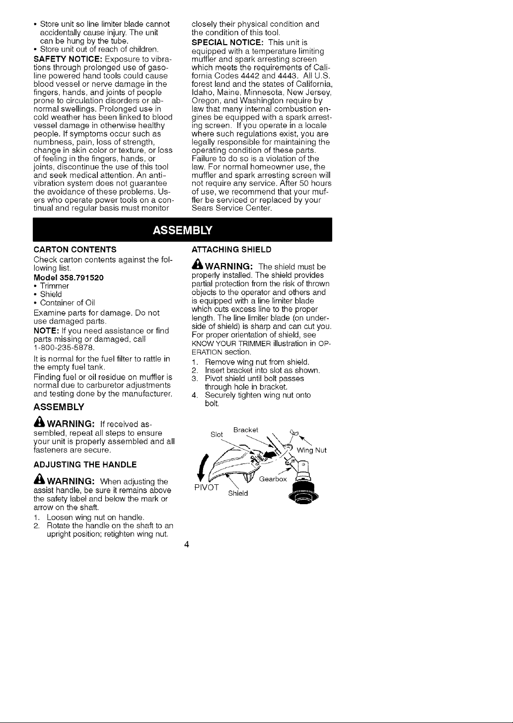
_,WARNING: The shield must be
properly installed. The shield provides
partial protection from the risk of thrown
objects to the operator and others and
is equipped with a line limiter blade
which cuts excess line to the proper
length. The line limiter blade (on under-
side of shield) is sharp and can cut you.
For proper orientation of shield, see
KNOW YOUR TRIMMER illustration in OP-
ERATION section.
1. Remove wing nut from shield.
2. Insert bracket into slot as shown.
3. Pivot shield until bolt passes
through hole in bracket.
4. Securely tighten wing nut onto
bolt.
Bracket
Slot
Wing Nut
PIVOT
Shield
Page 5
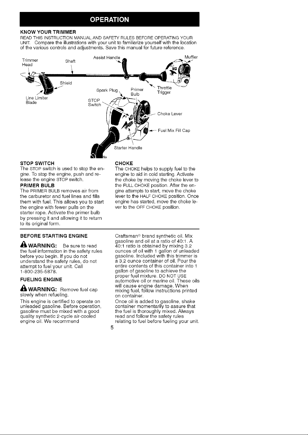
KNOW YOUR TRIMMER
READ THiS iNSTRUCTiON MANUAL AND SAFETY RULES BEFORE OPERATING YOUR
UNIT. Compare the illustrations with your unit to familiarize yourself with the location
of the various controls and adjustments. Save this manual for future reference.
Trimmer Shaft
Assist Hand_.,_ _,__._ler
Head _.
._hield
Line Limiter
Blade
Spark Plug _, Bulb Trigger
STOP
STOP SWITCH
The STOP switch isused to stop the en-
gine. To stop the engine, push and re-
lease the engine STOP switch.
PRIMER BULB
The PRIMER BULB removes air from
the carburetor and fuel lines and fills
them with fuel. This allows you to start
the engine with fewer pulls on the
starter rope. Activate the primer bulb
by pressing it and allowing it to return
to its original form.
Primer
Starter Handle
Throttle
Choke Lever
Fuel Mix Fill Cap
CHOKE
The CHOKE helps to supply fuel to the
engine to aid in cold starting. Activate
the choke by moving the choke lever to
the FULL CHOKE position. After the en-
gine attempts to start, move the choke
lever to the HALF CHOKE position. Once
engine has started, move the choke le-
ver to the OFF CHOKE position.
BEFORE STARTING ENGINE
_WARNING: Be sure to read
the fuel information in the safety rules
before you begin. If you do not
understand the safety rules, do not
attempt to fuel your unit. Call
1-800-235-5878.
FUELING ENGINE
_WARNING: Remove fuel cap
slowly when refueling.
This engine is certified to operate on
unleaded gasoline. Before operation,
gasoline must be mixed with a good
quality synthetic 2-cycle air-cooled
engine oil. We recommend
Craftsman <=>brand synthetic oil. Mix
gasoline and oil at a ratio of 40:1. A
40:1 ratio is obtained by mixing 3.2
ounces of oil with 1 gallon of unleaded
gasoline. Included with this trimmer is
a 3.2 ounce container of oil. Pour the
entire contents of this container into 1
gallon of gasoline to achieve the
proper fuel mixture. DO NOT USE
automotive oil or marine oil. These oils
will cause engine damage. When
mixing fuel, follow instructions printed
on container.
Once oil is added to gasoline, shake
container momentarily to assure that
the fuel is thoroughly mixed. Always
read and follow the safety rules
relating to fuel before fueling your unit.
5
Page 6

IMPORTANT
Experience indicates that alcohol
blended fuels (called gasohol or using
ethanol or methanol) can attract mois-
ture which leads to separation and
formation of acids during storage.
Acidic gas can damage the fuel sys-
tem of an engine while in storage.
To avoid engine problems, empty the
fuel system before storage for 30 days
or longer. Drain the gas tank, start the
engine and let it run until the fuel lines
and carburetor are empty. Use fresh
fuel next season.
Never use engine or carburetor clean-
er products in the fuel tank or perma-
nent damage may occur.
See the STORAGE section for addition-
al information.
HOW TO STOP YOUR UNIT
• To stop the engine, push and re-
lease the engine STOP switch. The
switch will automatically return to the
ON position. Wait 5 seconds before
attempting to restart unit to allow
switch to reset.
• If engine does not stop, move choke
to the FULL CHOKE position.
HOW TO START YOUR UNIT
_WARNING: The trimmer head
will turn while starting the engine.
Avoid any contact with the muffler. A
hot muffler can cause serious burns.
STARTING A COLD ENGINE (or a
warm engine after running out of
fuel)
_/, Starting Position
1. Set unit on a flat surface.
2. Slowly press the primer bulb 6
times.
3. Move choke lever to FULL CHOKE
position.
4. Squeeze the throttle trigger fully and
hold through all remaining steps.
Choke
Lever
Starter Handle
5. Pull starter rope handle sharply until
engine sounds as if it is trying to
start, but do not pull rope more than
6 times.
6. As soon as engine sounds as if it is
trying to start, move choke lever to
HALF CHOKE position.
7. Pull starter rope sharply until en-
gine runs, but no more than 6
pulls. NOTE: If the engine doesn't
start after 6 pulls (at the HALF
CHOKE position), move the choke
lever to the FULL CHOKE position
and press the primer bulb 6 times.
Squeeze and hold the throttle trig-
ger and pull the starter rope 2
more times. Move the choke lever
to the HALF CHOKE position and
pull the starter rope until the en-
gine runs, but no more than 6
pulls. If the engine still doesn't
start, it is probably flooded. Pro-
ceed to STARTING A FLOODED EN-
GINE.
8. Once the engine starts, allow it to
run 10 seconds, then move the
choke lever to the OFF CHOKE
position. Allow the unit to run for
30 more seconds at OFF CHOKE
before releasing the throttle trigger.
NOTE: If engine dies with the
choke lever in the OFF CHOKE
position, move the choke lever to
the HALF CHOKE position and pull
the rope until engine runs, but no
more than 6 pulls.
Page 7

STARTINGAWARMENGINE
1. MovethechokelevertotheHALF
CHOKEposition.
2. Squeezeandholdthethrottletrig-
ger.Keepthrottletriggerfully
squeezeduntiltheengineruns
smoothly.
3. Pullstarterropesharplyuntilengine
runs, but no more than 5 pulls.
4. Allow engine to run 15 seconds,
then move the choke lever to OFF
CHOKE.
NOTE: If engine has not started, pull
starter rope 5 more pulls. If engine still
does not run, it is probably flooded.
STARTING A FLOODED ENGINE
Flooded engines can be started by
placing the choke lever in the OFF
CHOKE position; then, pull the rope to
clear the engine of excess fuel. This
could require pulling the starter handle
many times depending on how badly
the unit is flooded.
If the unit still doesn't start, refer to
TROUBLESHOOTING TABLE or call
1-800-235-5878.
OPERATING INSTRUCTIONS
It is recommended that the engine
not be operated longer than 1 min-
ute at full throttle.
OPERATING POSITION
ALWAYS WEAR: _ !._r_Eye protection
Heavy shoes II { i '_
cot,tomyoo ,eI it r,0ht
A_,WARNING: Always wear eye
protection. Never lean over the trim-
mer head. Rocks or debris can rico-
chet or be thrown into eyes and face
and cause blindness or other serious
injury.
When operating unit, stand as shown
and check for the following:
• Wear eye protection and heavy
clothing.
• Hold trigger handle with right hand
and assist handle with left hand.
• Keep unit below waist level.
• Cut only from your left to your right to
ensure debris is thrown away from
you. Without bending over, keep line
near and parallel to the ground and
not crowded into material being cut.
Do not run the engine at a higher
speed than necessary. The cutting
line will cut efficiently when the engine
is run at less than full throttle. At lower
speeds, there is less engine noise and
vibration. The cutting line will last
longer and will be less likely to "weld"
onto the spool.
Always release the throttle trigger and
allow the engine to return to idle
speed when not cutting.
To stop engine:
• Release the throttle trigger.
• Push and release the engine STOP
switch.
TRIMMER LINE ADVANCE
The trimmer line will advance approxi-
mately 2 inches (5 cm) each time the
bottom of the trimmer head is tapped
on the ground with the engine running
at full throttle.
The most efficient line length is the
maximum length allowed by the line
limiter.
Always keep the shield in place when
the tool is being operated.
To advance line:
• Operate the engine at full throttle.
• Hold the trimmer head parallel to
and above the grassy area.
• Tap the bottom of the trimmer head
lightly on the ground one time. Ap-
proximately 2 inches (5 cm) of line
will be advanced with each tap.
Always tap the trimmer head on a
grassy area. Tapping on surfaces such
as concrete or asphalt can cause ex-
cessive wear to the trimmer head.
If the line is worn down to 2 inches (5
cm) or less, more than one tap will be
required to obtain the most efficient line
length.
,4g&WARNING: Use only 0.080 inch
(2 ram) diameter round line. Other
sizes and shapes of line will not ad-
vance properly and will result in im-
proper cutting head function or can
cause serious injury. Do not use other
materials such as wire, string, rope,
etc. Wire can break off during cutting
and become a dangerous missile that
can cause serious injury.
7
Page 8

CUTTINGMETHODS
Useminimumspeedanddonot
crowdthelinewhencuttingaround
hardobjects(rock,gravel,fence
posts,etc.),whichcandamagethe
trimmerhead,becomeentangledin
theline,orbethrowncausingaseri-
oushazard.
• Thetipofthelinedoesthecutting.
Youwillachievethebestperform-
anceandminimumlinewearbynot
crowdingthelineintothecutting
area.Therightandwrongwaysare
shownbelow.
Tipoflinedoes Linecrowdedh_to
thecutting.
Right W_ong
• The line will easily remove grass
and weeds from around walls,
fences, trees and flower beds, but it
also can cut the tender bark of trees
or shrubs and scar fences. To help
avoid damage especially to delicate
vegetation or trees with tender bark,
shorten line to 4-5 inches (10-13
cm) and use at less than full throttle.
• For trimming or scalping, use less
than full throttle to increase line life
and decrease head wear, especially:
• During light duty cutting.
• Near objects around which the line
can wrap such as small posts,
trees or fence wire.
• For mowing or sweeping, use full
throttle for a good clean job.
TRIMMING - Hold the bottom of the
trimmer head about 3 inches (8 cm)
above the ground and at an angle. Al-
low only the tip of the line to make
contact. Do not force trimmer line into
work area.
Trimming
SCALPING-Thescalpingtechnique
removesunwantedvegetationdownto
theground.Holdthebottomofthe
trimmerheadabout3inches(8cm)
abovethegroundandatanangle.Al-
lowthetipofthelinetostrikethe
groundaroundtrees,posts,monu-
ments,etc.Thistechniqueincreases
linewear.
Scalping
MOWING - Your trimmer is ideal for
mowing in places conventional lawn
mowers cannot reach. In the mowing
position, keep the line parallel to the
ground. Avoid pressing the head into
the ground as this can scalp the
ground and damage the tool.
Mowing
SWEEPING - The fanning action of
the rotating line can be used for a
quick and easy clean up. Keep the
line parallel to and above the surfaces
being swept and move the tool from
side to side.
Sweeping
3 inches (8 sm
above ground
Page 9

MAINTENANCE SCHEDULE
WARNING: Disconnect the spark plug before performing maintenance
except for carburetor adjustments.
CARE & MAINTENANCE TASK
Check for loose fasteners and parts
Check for damaged or worn parts
Inspect and clean unit and labels
Clean air filter
Inspect muffler and spark arresting screen
Replace spark plug
GENERAL RECOMMEN DATIONS
The warranty on this unit does not
cover items that have been subjected
to operator abuse or negligence. To
receive full value from the warranty,
the operator must maintain unit as
instructed in this manual. Various ad-
justments will need to be made peri-
odically to properly maintain your unit.
CHECK FOR LOOSE
FASTENERS AND PARTS
• Spark Plug Boot
• Air Filter
• Housing Screws
• Assist Handle Screw
• Debris Shield
CHECK FOR DAMAGED OR
WHEN TO PERFORM
Before each use
Before each use
After each use
Every 5 hours of operation
Every 50 hours of operation
Yearly
CLEAN AIR FILTER
A dirty air filter decreases engine per-
formance and increases fuel consump-
tion and harmful emissions. Always
clean after every 5 hours of operation.
1. Clean the cover and the area
around it to keep dirt from falling into
the carburetor chamber when the
cover is removed.
2. Remove parts as illustrated.
NOTE: To avoid creating a fire hazard
or producing harmful evaporative
emissions, do not clean filter in gaso-
line or other flammable solvent.
3. Wash the filter in soap and water.
4. Allow filter to dry.
5. Replace parts.
Button
WORN PARTS
Contact Sears Service Center for re-
placement of damaged or worn parts.
• STOP Switch - Ensure STOP switch
functions properly by pushing and
releasing the switch. Make sure en-
gine stops. Wait 5 seconds before
attempting to restart unit to allow
switch to reset. Restart engine and
continue.
• Fuel Tank - Discontinue use of unit
if fuel tank shows signs of damage
or leaks.
• Debris Shield - Discontinue use of
unit if debris shield is damaged.
INSPECT AND CLEAN UNIT AND
LABELS
• After each use, inspect complete
unit for loose or damaged parts.
Clean the unit and labels using a
damp cloth with a mild detergent.
• Wipe off unit with a clean dry cloth.
INSPECT MUFFLER AND SPARK
ARRESTING SCREEN
,_WARNING: The muffler on this
product contains chemicals known to
the State of California to cause cancer.
As your unit is used, carbon deposits
build up on the muffler and spark ar-
resting screen.
For normal homeowner use, however,
the muffler and spark arresting screen
will not require any service. After 50
hours of use, we recommend that your
muffler be serviced or replaced by your
Sears Service Center.
Air Filter Cover
Air Filter
Page 10

REPLACE SPARK PLUG
Replace the spark plug each year to
ensure the engine starts easier and
runs better. Set spark plug gap at
0.025 inch. Ignition timing is fixed and
nonadjustable.
1. Twist, then pull off spark plug boot.
2. Remove spark plug from cylinder
and discard.
3. Replace with Champion RCJ-6Y
spark plug and tighten securely with
a 3/4 inch socket wrench.
4. Reinstall the spark plug boot.
LINE REPLACEMENT
1= Push and release the engine
STOP switch.
2. Disconnect the spark plug wire.
3. Remove spool by firmly pulling on
tap button.
4. Clean entire surface of hub and
spool.
5. Replace with a pre-wound spool, or
cut two lengths of 12-1/2 feet (3.8
meters) of 0.080" (2 mm) diameter
Craftsman'> brand line.
_tlWARNING: Never use wire,
rope, string, etc., which can break off
and become a dangerous missile.
6. Insert ends of line about 1/2 inch
(1 cm) into the small holes on the
inside of the spool.
Spool _ />_/7 _
ZqWJ_/sma,,
if St/ Ho,es
7. Wind line evenly and tightly onto
spool. Wind in the direction of the
arrow on the spool.
8. Push the line into the notches, leav-
ing 3 to 5 inches (7 - 12 cm) un-
wound.
9. Insert the line into the exit holes in
the hub as shown in the illustration.
Line exit holes Line in Notch
\ x
Line in Notch
10. Align the notches with the line exit
holes.
11. Push spool into hub until it snaps
into place.
12. Pull the lines extending outside of
the hub to release them from the
notches.
REPLACING THE CUTTING HEAD
1. Align hole in the dust cup with the
hole inthe side of the gearbox by
rotating the dust cup.
2. Insert a small screwdriver into
aligned holes. This will keep the
shaft from turning while removing
and installing trimmer head.
Screwdriv_
3. While holding the screwdriver in
position, remove trimmer head by
turning clockwise.
4. Thread replacement trimmer head
onto the shaft by turning counter-
clockwise. Tighten until secure.
5. Remove the screwdriver.
CARBURETOR ADJUSTMENT
,_WARNING: Keep others away
when making idle speed adjustments.
The trimmer head will be spinning dur-
ing this procedure. Wear your protec-
tive equipment and observe all safety
precautions.
The carburetor has been carefully set
at the factory. Adjustments may be
necessary if you notice any of the fol-
lowing conditions:
• Engine will not idle when the throttle is
released.
Make adjustments with the unit sup-
ported so the cutting attachment is off
the ground and will not make contact
with any object. Hold the unit by hand
while running and making adjust-
ments. Keep all parts of your body
away from the cutting attachment and
muffler.
lO
Page 11

Idle Speed Adjustment
Allow engine to idle. Adjust speed until
engine runs without stalling (idle
speed too slow).
• Turn idle speed screw clockwise to
increase engine speed if engine
stalls or dies.
• Turn idle speed screw counterclock-
wise to decrease engine speed.
Idle Speed Screw
Air Filter Cover
If you require further assistance or are
unsure about performing this proce-
dure, contact your Sears Service Cen-
ter or call our customer assistance
help line at 1-800-235-5878.
dt_WARNING: Perform the follow-
ing steps after each use:
• Allow engine to cool, and secure the
unit before storing or transporting.
• Store unit and fuel in a well venti-
lated area where fuel vapors cannot
reach sparks or open flames from
water heaters, electric motors or
switches, furnaces, etc.
• Store unit with all guards in place.
Position unit so that any sharp ob-
ject cannot accidentally cause injury.
• Store unit and fuel well out of the
reach of children=
SEASONAL STORAGE
Prepare unit for storage at end of sea-
son or if it will not be used for 30 days
or more.
If your unit is to be stored for a period
of time:
• Clean the entire unit before lengthy
storage.
• Store in a clean dry area.
• Lightly oil external metal surfaces.
FUEL SYSTEM
Under FUELING ENGINE in the OPERA-
TION section of this manual, see mes-
sage labeled IMPORTANT regarding
the use of gasohol in your engine.
Fuel stabilizer is an acceptable alter-
native in minimizing the formation of
fuel gum deposits during storage. Add
stabilizer to the gasoline in the fuel
tank or fuel storage container. Follow
the mix instructions found on stabilizer
container. Run engine at least 5 min-
utes after adding stabilizer.
Craftsman <_40:1,2-cycle engine oil
(air cooled) is already blended with
fuel stabilizer. If you do not use this
Sears oil, you can add a fuel stabilizer
to your fuel tank.
INTERNAL ENGINE
• Remove spark plug and pour 1 tea-
spoon of 40:1,2-cycle engine oil (air
cooled) through the spark plug
opening. Slowly pull the starter rope
8 to 10 times to distribute oil.
• Replace spark plug with new one of
recommended type and heat range.
• Clean air filter.
• Check entire unit for loose screws,
nuts, and bolts. Replace any dam-
aged, broken, or worn parts.
• At the beginning of the next season,
use only fresh fuel having the proper
gasoline to oil ratio.
OTHER
• Do not store gasoline from one sea-
son to another.
• Replace your gasoline can if it starts
to rust.
11
Page 12

TROUBLESHOOTING TABLE
_, WARNING: Always stop unit and disconnect spark plug before perform-
ing all of the recommended remedies below except remedies that require
operation of the unit.
TROUBLE
Engine will not
start.
Engine will
not idle
properly.
Engine will not
accelerate,
lacks power.
or dies under
a load.
CAUSE
1. Engine flooded.
2. Fuel tank empty.
3. Spark plug not firing.
4. Fuel not reaching 4.
carburetor.
5. Carburetor requires 5.
adjustment.
1. Carburetor requires 1.
adjustment.
2. Crankshaft seals worn. 2.
3. Compression low. 3.
1. Air filter dirty. 1.
2. Spark plug fouled. 2.
3. Carburetor requires 3.
adjustment.
4. Carbon build-up on 4.
muffler outlet screen.
5. Compression low. 5.
REMEDY
1,
See "Starting a Flooded Engine" in
Operation Section.
2.
Fill tank with correct fuel mixture.
3.
Install new spark plug.
Check for dirty fuel filter; replace.
Check for kinked or split fuel line;
repair or replace.
Contact Sears Service (see back cover).
See "Carburetor Adjustment" in
Service and Adjustments Section.
Contact Sears Service (see back cover).
Contact Sears Service (see back cover).
Clean or replace air filter.
Clean or replace plug and regap.
Contact Sears Service (see back cover).
Contact Sears Service (see back cover).
Contact Sears Service (see back cover).
Engine
smokes
excessively.
Engine runs
hot.
1. Choke partially on. 1.
2. Fuel mixture incorrect. 2.
3. Air filter dirty. 3.
4. Carburetor requires 4.
adjustment.
1. Fuel mixture incorrect. 1.
2. Spark plug incorrect. 2.
3. Carburetor requires 3.
adjustment.
4. Carbon build-up on 4.
muffler outlet screen.
Adjust choke.
Empty fuel tank and refill with
correct fuel mixture.
Clean or replace air filter.
Contact Sears Service (see back cover).
See "Fueling Engine" in Operation
section.
Replace with correct spark plug.
Contact Sears Service (see back cover).
Contact Sears Service (see back cover).
12
Page 13

YOUR WARRANTY RIGHTS AND OB-
LIGATIONS: The U.S. Environmental
Protection Agency/California Air Re-
sources Board and Sears, Roebuck
and Co., U.S.A., are pleased to explain
the emissions control system warranty
on your year 2005 and later small off-
road engine. In California, all small off-
road engines must be designed, built,
and equipped to meet the State's strin-
gent anti-smog standards. Sears must
warrant the emission control system on
your small off-road engine for the peri-
ods of time listed below provided there
has been no abuse, neglect, or improp-
er maintenance of your small off-road
engine. Your emission control system
includes parts such as the carburetor
and the ignition system. Where a war-
rantable condition exists, Sears will re-
pair your small off-road engine at no
cost to you. Expenses covered under
warranty include diagnosis, parts and
labor. MANUFACTURER'S WARRAN-
TY COVERAGE: If any emissions re-
lated part on your engine (as listed un-
der Emissions Control Warranty Parts
List) is defective or a defect in the mate-
rials or workmanship of the engine
causes the failure of such an emission
related part, the part will be repaired or
replaced by Sears. OWNER'S WAR-
RANTY RESPONSIBILITIES: As the
small off-road engine owner, you are
responsible for the performance of the
required maintenance listed in your in-
struction manual. Sears recommends
that you retain all receipts covering
maintenance on your small off-road en-
gine, but Sears cannot deny warranty
solely for the lack of receipts or for your
failure to ensure the performance of all
scheduled maintenance. As the small
off-road engine owner, you should be
aware that Sears may deny you war-
ranty coverage if your small off-road
engine or a part of it has failed due to
abuse, neglect, improper maintenance,
unapproved modifications, or the use of
parts not made or approved by the orig-
inal equipment manufacturer. You are
responsible for presenting your small
off-road engine to a Sears authorized
repair center as soon as a problem ex-
ists. Warranty repairs should be com-
pleted in a reasonable amount of time,
not to exceed 30 days. If you have any
questions regarding your warranty rights
and responsibilities, you should contact
your nearest authorized service center
or call Sears at 1-800-469-4663.
WARRANTY COMMENCEMENT
DATE: The warranty period begins on
the date the small off-road engine is
purchased. LENGTH OF COVERAGE:
This warranty shall be for a period of
two years from the initial date of pur-
chase. WHAT IS COVERED: REPAIR
OR REPLACEMENT OF PARTS. Re-
pair or replacement of any warranted
part will be performed at no charge to
the owner at an approved Sears Servi-
ce Center. Ifyou have any questions
regarding your warranty rights and re-
sponsibilities, you should contact your
nearest authorized service center or call
Sears at 1-800-469-4663. WARRAN-
TY PERIOD: Any warranted part which
is not scheduled for replacement as re-
quired maintenance, or which is sched-
uled only for regular inspection to the
effect of "repair or replace as neces-
sary" shall be warranted for 2 years.
Any warranted part which is scheduled
for replacement as required mainte-
nance shall be warranted for the period
of time up to the first scheduled replace-
ment point for that part. DIAGNOSIS:
The owner shall not be charged for
diagnostic labor which leads to the de-
termination that a warranted part is de-
fective if the diagnostic work is per-
formed at an approved Sears Service
Center. CONSEQUENTIAL DAM-
AGES: Sears may be liable for dam-
ages to other engine components
caused by the failure of a warranted
part still under warranty. WHAT IS NOT
COVERED: All failures caused by
abuse, neglect, or improper mainte-
nance are not covered. ADD-ON OR
MODIFIED PARTS: The use of add-on
or modified parts can be grounds for
disallowing a warranty claim. Sears is
not liable to cover failures of warranted
parts caused by the use of add-on or
modified parts. HOW TO FILE A
CLAIM: If you have any questions re-
garding your warranty rights and re-
sponsibilities, you should contact your
nearest authorized service center or call
Sears at 1-800-469-4663.
13
Page 14

WHERE TO GET WARRANTY SER-
VICE: Warranty services or repairs shall
be provided at all Sears Service Cen-
ters. Call 1-800-469-4663. MAINTE-
NANCE, REPLACEMENT AND RE-
PAIR OF EMISSION RELATED
PARTS: Any Sears approved replace-
ment part used in the performance of
any warranty maintenance or repair on
emission related parts will be provided
The information on the product label indicates to which standard your engine is certified.
Example: (Year) EPA Phase Ior Phase II and/or CALIFORNIA.
without charge to the owner if the part is
under warranty. EMISSION CONTROL
WARRANTY PARTS LIST: Carburetor,
Ignition System: Spark Plug (covered
up to maintenance schedule), Ignition
Module, Muffler including catalyst.
MAINTENANCE STATEMENT: The
owner is responsible for the perfor-
mance of all required maintenance as
defined in the instruction manual.
This engine is certified to be emissions compliant for the following use:
[] Moderate (50 hours)
[] Intermediate (125 hours)
[] Extended (300 hours)
14
 Loading...