

Craftsman 247889360 Owner’s Manual

Operator's Manual
12.5 Horse Power
36-inch Wide Cut Mower
Model No. 247.889360
CAUTION: Before using
this product, read this
manual and follow all
Safety Rules and
Operating Instructions.
Safety
Assembly
Operation
Maintenance
For answers to your questions
about this product, call:
1-800-659-5917
Sears Craftsman Help Line
5 a.m. - 5 p.m., Mon - Sat
Parts
Espahol, p.60
Sears, Roebuck and Co., Hoffman Estates, IL 60179, U.S.A.
Visit our Sears website: www.sears.com/craftsman
Printed in U.S.A. FORM NO. 02005404 Rev 09_0
(4/2009)

WarrantyStatement 2 Maintenance 17
SafetyInstructions 3 ServiceandAdjustments 21
SlopeGuide 6 Off-SeasonStorage 24
RepairProtectionAgreement 7 AccessoriesandAttachments 24
SafetyLabels 8 Troubleshooting 25
ProductSpecification 10 PartsList 26
Assembly 11 Espanol 60
Operation 12
Craftsman Two Year Limited Warranty on 36-inch Wide Cut Mower
When used and maintained according to all supplied instructions, if this Craftsman product fails due to a defect in
material within two years from the date of purchase, return it to any Sears store, Parts & Repair Service Center, or
other Craftsman outlet in the United States for free repair. In-home warranty service is available, but you will have
to pay a trip charge.
This Warranty does not cover:
• Expendable items which become worn during normal use, such as rotary mower blades, blade adaptors,
spark plugs, air cleaners, belts, and oil filters.
• Tire replacement or repair caused by punctures from outside objects, such as nails, thorns, stumps, or glass.
• Repairs necessary because of operator abuse, including but not limited to, damage caused by objects, such
as stones, metal debris or oversized pieces of wood, or impacting objects that bend the frame or crankshaft,
or over-speeding the engine.
• Repairs necessary because of operator negligence, including but not limited to, electrical and mechanical
damage caused by improper storage, failure to use the proper grade and amount of engine oil, or failure to
maintain the equipment according to the instructions contained in the operator's manual.
• Engine (fuel system) cleaning or repairs caused by fuel determined to be contaminated or oxidized (stale). In
general, fuel should be used within 30 days of its purchase date.
This warranty applies for only 90 days if this product is ever used for commercial or rental purposes.
This warranty applies only while this product is used inthe United States.
This warranty gives you specific legal rights and you may also have other rights, which vary from state to state.
Sears, Roebuck and Co., Hoffman Estates, IL 60179
MODEL NUMBER
Model Number .........................................................
Serial Number ...........................................................
Date of Purchase ......................................................
Record the model number, serial number and date of
purchase above.
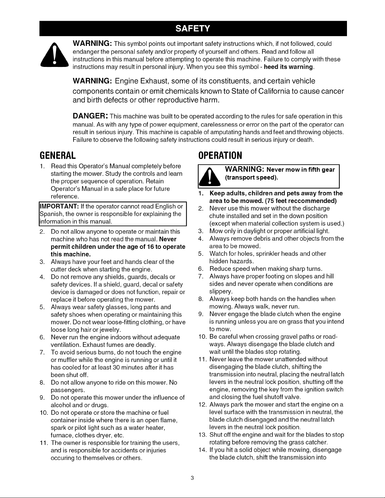
WARNING: This symbol points out important safety instructions which, if not followed, could
endanger the personal safety and/or property of yourself and others. Read and follow all
instructions in this manual before attempting to operate this machine. Failure to comply with these
instructions may result in personal injury. When you see this symbol - heed its warning.
WARNING: Engine Exhaust, some of its constituents, and certain vehicle
components contain or emit chemicals known to State of California to cause cancer
and birth defects or other reproductive harm.
DANGER: This machine was built to be operated according to the rules for safe operation inthis
manual. As with any type of power equipment, carelessness or error on the part of the operator can
result in serious injury. This machine is capable of amputating hands and feet and throwing objects.
Failure to observe the following safety instructions could result in serious injury or death.
GENERAL
1. Read this Operator's Manual completely before
starting the mower. Study the controls and learn
the proper sequence of operation. Retain
Operator's Manual in a safe place for future
reference.
operator English
Spanish, the owner is responsible for explaining the
IMPORTANT: Ifthe cannot read
information inthis manual.
2. Do not allow anyone to operate or maintain this
machine who has not read the manual. Never
permit children under the age of 16 to operate
this machine.
3. Always have your feet and hands clear of the
cutter deck when starting the engine.
4. Do not remove any shields, guards, decals or
safety devices. If a shield, guard, decal or safety
device is damaged or does not function, repair or
replace it before operating the mower.
5. Always wear safety glasses, long pants and
safety shoes when operating or maintaining this
mower. Do not wear loose-fitting clothing, or have
loose long hair or jewelry.
6. Never run the engine indoors without adequate
ventilation. Exhaust fumes are deadly.
7. To avoid serious burns, do not touch the engine
or muffler while the engine is running or until it
has cooled for at least 30 minutes after it has
been shut off.
8. Do not allow anyone to ride on this mower. No
passengers.
9. Do not operate this mower under the influence of
alcohol and or drugs.
10. Do not operate or store the machine or fuel
container inside where there is an open flame,
spark or pilot light such as a water heater,
furnace, clothes dryer, etc.
11. The owner is responsible for training the users,
and is responsible for accidents or injuries
occuring to themselves or others.
or
OPERATION
WARNING: Never mow in fifth gear I
(transport speed).
I
Keep adults, children and pets away from the
area to be mowed. (75 feet reccommended)
2. Never use this mower without the discharge
chute installed and set in the down position
(except when material collection system is used.)
3. Mow only in daylight or proper artificial light.
4. Always remove debris and other objects from the
area to be mowed.
5. Watch for holes, sprinkler heads and other
hidden hazards.
6. Reduce speed when making sharp turns.
7. Always have proper footing on slopes and hill
sides and never operate when conditions are
slippery.
8. Always keep both hands on the handles when
mowing. Always walk, never run.
9. Never engage the blade clutch when the engine
is running unless you are on grass that you intend
to mow.
10. Be careful when crossing gravel paths or road-
ways. Always disengage the blade clutch and
wait until the blades stop rotating.
11. Never leave the mower unattended without
disengaging the blade clutch, shifting the
transmission into neutral, placing the neutral latch
levers in the neutral lock position, shutting off the
engine, removing the key from the ignition switch
and closing the fuel shutoff valve.
12. Always park the mower and start the engine on a
level surface with the transmission in neutral, the
blade clutch disengaged and the neutral latch
levers in the neutral lock position.
13. Shut off the engine and wait for the blades to stop
rotating before removing the grass catcher.
14. If you hit a solid object while mowing, disengage
the blade clutch, shift the transmission into
neutral,placetheneutrallatchleversintheneutral
lockpositionandstoptheengine.Disconnectthe
sparkplugwire(s)andinspectfordamage.Repair
anydamageandmakesurethebladesareingood
conditionandthebladeboltsaretightbefore
restartingtheengine.
15.Donotmowexcessivelysteepslopes(Nomore
than15degreesora26.8%grade).Mowacross
theslope.
the slope. You could slip and slide into the
_ ARNING: Do not mow up and down
16. Never raise the mower deck while the blades are
17. Never walk or stand on the discharge side of a
18. Always disconnect the spark plug wire to prevent
19. Keep the mower and especially the engine clean
20. The operator presence control levers located at
mower, or the mower could loose traction
and steering control.
rotating.
mower with the engine running. Disengage the
blade clutch if another person approaches while
you are operating a mower.
the engine from accidentally starting before
performing any maintenance on this mower.
and free of grease, grass and leaves to reduce the
chance of fire and to permit proper cooling.
each handle are designed for your safety. Do not
try to defeat their operation. If the blade clutch is
engaged or the transmission is in gear, releasing
both handles will shut off the mower's engine.
MAINTENANCEANDSTORAGE
WARNING: Never let children or
untrained people operate or service this
mower.
1. Never tamper with safety devices. Check their
proper operation regularly.
2. Check bolts and screws for proper tightness at
frequent intervals to keep the machine in safe
working condition. Also, visually inspect machine
for any damage and repair, if needed.
3. Before cleaning, repairing, or inspecting, stop the
engine and make certain all moving parts have
stopped. Disconnect the spark plug wire and
ground it against the engine to prevent unintended
starting.
4. Do not change the engine governor settings or
overspeed the engine. The governor controls the
maximum safe operating speed of the engine.
5. Maintain or replace safety and instruction labels, as
necessary.
6. Follow this manual for safe loading, unloading,
transporting, and storage of this machine. (See
page 16 and page 24)
7. Never store the machine or fuel container inside
where there is an open flame, spark or pilot light
such as a water heater, furnace, clothes dryer, etc.
8. Always refer to the operator's manual for proper
instructions on off-season storage. (See page 24)
9. Ifthe fuel tank has to be drained, do this outdoors.
Observe proper disposal laws and regulations for gas,
oil, etc. to protect the environment.
RELATEDTOFUEL
1. Fuel is highly flammable and its vapors can explode
if ignited. Please respect it.
2. Do not smoke or permit others to smoke while han-
dling fuel.
3. Always use approved containers for fuel and fill
slowly to decrease the chance of static electricity
buildup and spillage.
4. Store fuel in well ventilated and unoccupied build-
ings away from sparks and flames.
5. When dispensing gasoline into approved contain-
ers, place the container on the ground when refuel-
ing to avoid a possible static electricity ignition of
fuel vapors.
6. Do not fill containers while it is inside a vehicle,
trunk, the bed of a pickup or floor of a trailer.
7. Always shut off the engine and permit it to cool
before removing the fuel tank cap.
8. Always fill the fuel tank outdoors.
9. If the fuel container spout will not fit inside the fuel
tank opening, use a funnel.
10. When filling the fuel tank, stop when the fuel reaches
one inch from the top. This space is necessary fortank
expansion. Do not overfill.
11. Wipe up any spilled fuel.
12. Do not operate or store the machine or fuel
container inside where there is an open flame,
spark or pilot light such as a water heater, furnace,
clothes dryer, etc.
SLOPEOPERATION
DO:
• Mow across slopes, and exercise caution when
turning or changing direction.
• Watch for holes, ruts or bumps and hidden objects.
• Be sure of your footing. A slip could cause personal
injury.
• Check the area thoroughly before mowing.
• Slow down and use extra care.
DO NOT:
• Do not mow up and down slopes.
• Do not mow near drop offs, ditches, embankments,
etc. The mower could suddenly turn over if a wheel is
over the edge of a cliff or ditch, or if an edge caves in.
• Do not mow on wet or slippery grass. Reduced
traction could cause sliding.
• Do not mow on slopes greeater than 15 degrees as
shown on the slope gauge.

FIRSTTIME OPERATORS
• Start off in a flat, open, area.
• Keep bystanders away.
• Set the throttle to low speed.
• Practice maneuvering (forward, turn left, turn right,
reverse), without the mower deck engaged.
5

USE THIS PAGE AS A GUIDE TO DETERMINE SLOPES WHERE YOU MAY NOT OPERATE SAFELY.
I
I
I
B
r.D
15 °
_ WARNING
Do not mow on inclines with a slope in excess of 15 degrees (a rise of approximately 2-1/2 feet every 10 feet). A riding mower
could overturn and cause serious injury. If operating a walk-behind mower on such a slope, it is extremely difficult to maintain
your footing and you could slip, resulting in serious injury.
Operate ZERO-TURN mowers across the face of slopes, never up and down slopes.
Operate WALK-BEHIND mowers across the face of slopes, never up and down slopes.

Congratulations on making a smart purchase. Your new
Craftsman® Professional product is designed and
manufactured for years of dependable operation. But like all
products, it may require repair from time to time. That's when
having a Repair Protection Agreement can save you money and
aggravation.
Here's what the Repair Protection Agreement* includes:
Expert service by our 10,000 professional repair
specialists
Unlimited service and no charge for parts and labor
on all covered repairs
Product replacement up to $1500 if your covered
product cannot be fixed
,_ Discount of 10% from regular price of service and
related installed parts not covered by the agreement;
also, 10% off regular price of preventive maintenance
check
Fast help by phone- we call it Rapid Resolution- phone
support from a Sears representative. Think of us as a
'_talking owner's manual."
Once you purchase the Repair Protection Agreement, a simple
phone call is all that it takes for you to schedule service. You can
call anytime day or night, or schedule a service appointment
online.
The Repair Protection Agreement isa risk-free purchase. If you
cancel for any reason during the product warranty period, we will
provide a full refund. Or, a prorated refund anytime after the
product warranty period expires. Purchase your Repair
Protection Agreement today!
Some limitations and exclusions apply. For prices and
additional information in the U.S.A. call 1-800-827-6655.
*Coverage in Canada varies on some items. For full details
call Sears Canada at 1-800-361-6665.
Sears Installation Service
For Sears professional installation of home appliances, garage
door openers, water heaters, and other major home items, inthe
U.S.A. or Canada call 1-800-4-MY-HOME®
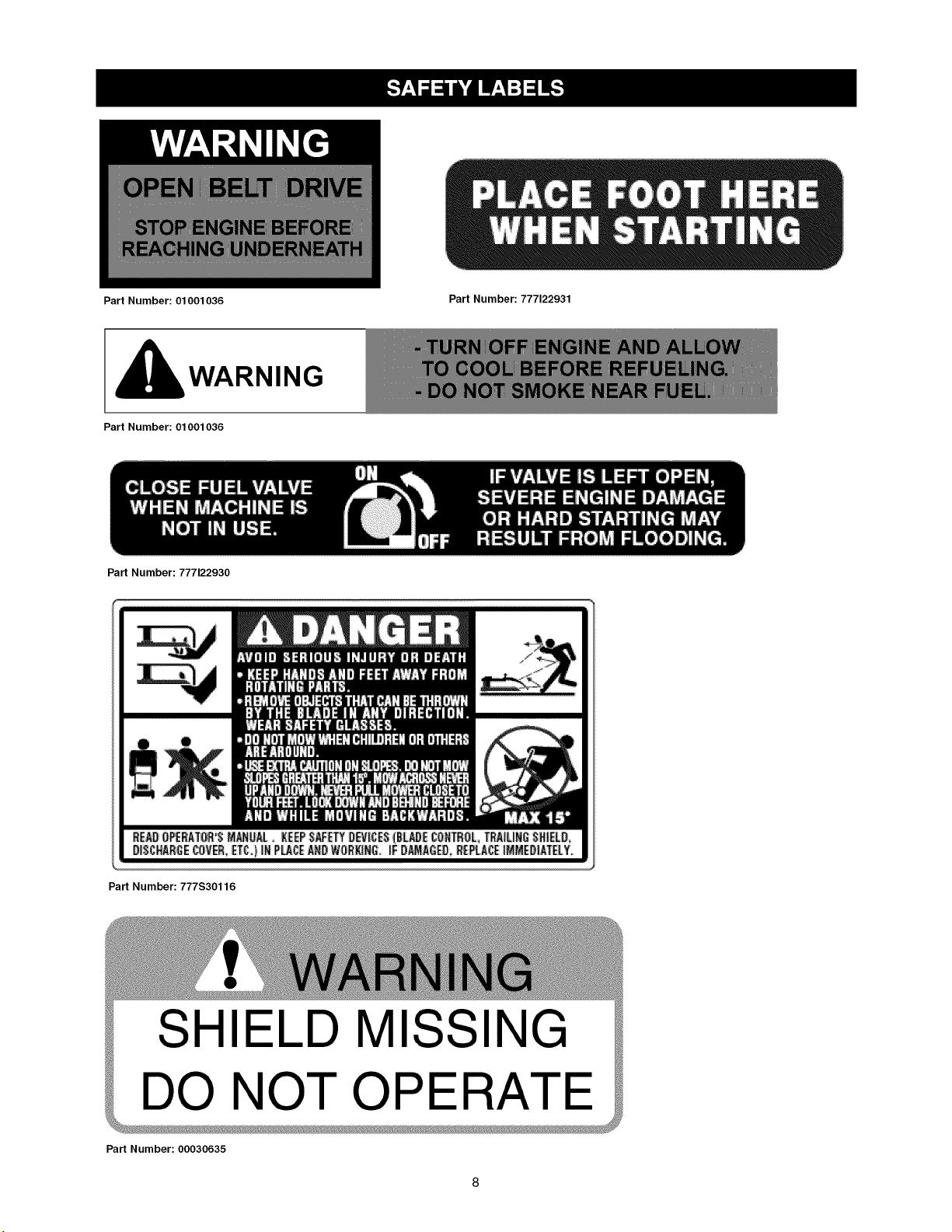
Part Number: 01001036
I_WARNING
Part Number: 01001036
Part Number: 777122930
Part Number: 777122931
Part Number: 777S30116
SHIELD MISSING
DO NOT OPERAT
Part Number: 00030635
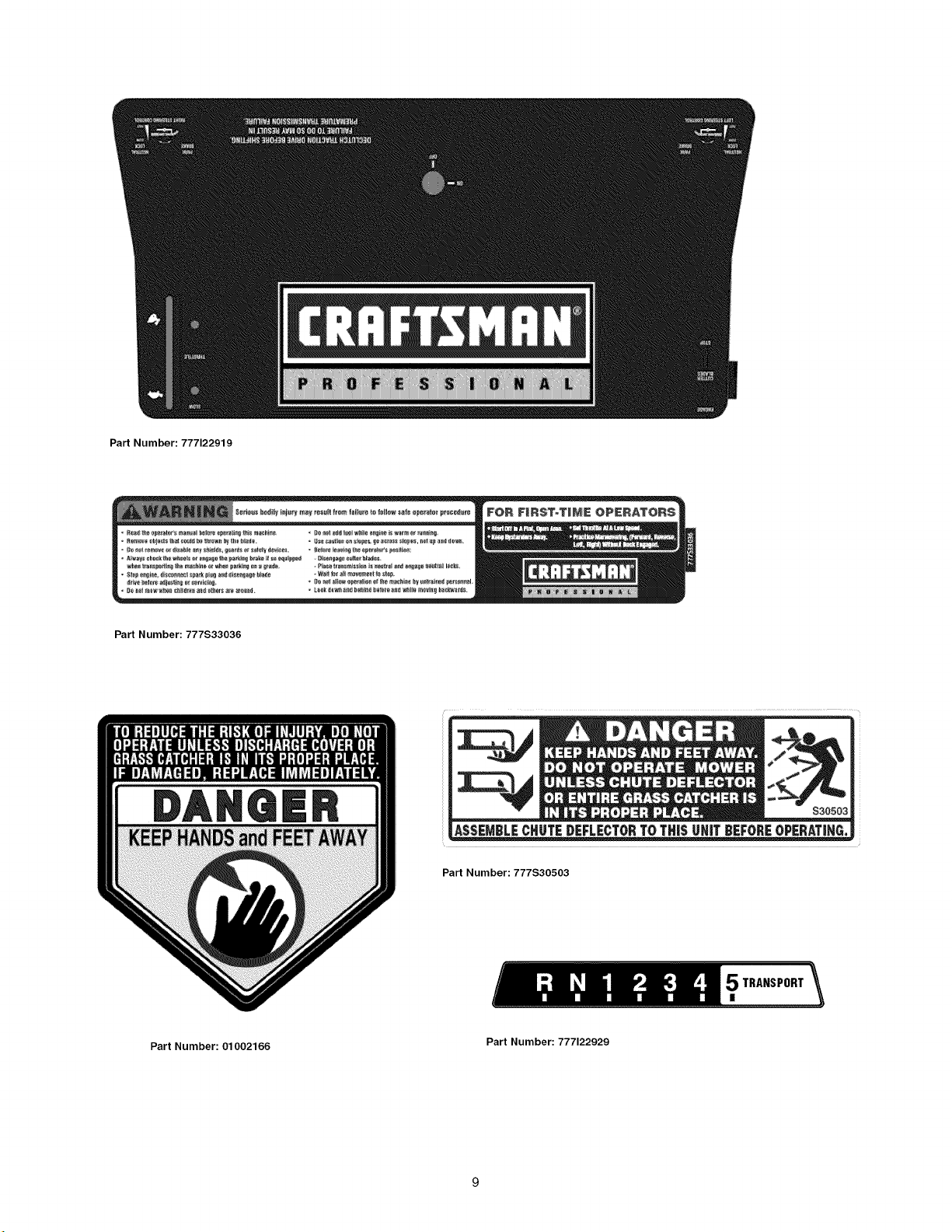
PartNumber:777122919
PartNumber:777S33036
PartNumber:777S30503
Part Number: 01002166
5TRANSPORT
|
Part Number: 777122929
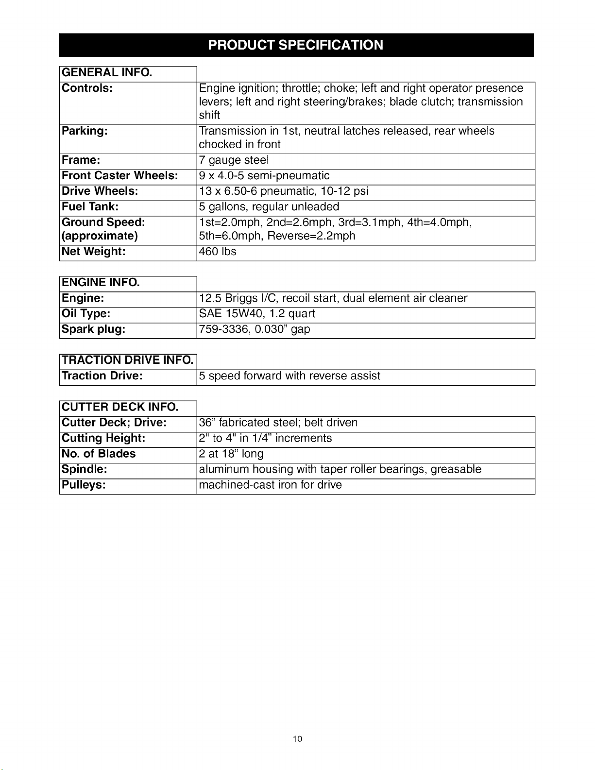
GENERAL INFO.
Controls: Engine ignition; throttle; choke; left and right operator presence
levers; left and right steering/brakes; blade clutch; transmission
shift
Parking: Transmission in 1st, neutral latches released, rear wheels
chocked in front
Frame: 7 gauge steel
Front Caster Wheels: 9 x 4.0-5 semi-pneumatic
Drive Wheels: 13 x 6.50-6 pneumatic, 10-12 psi
Fuel Tank: 5 gallons, regular unleaded
Ground Speed: l st=2.0mph, 2nd=2.6mph, 3rd=3.1mph, 4th=4.0mph,
(approximate) 5th=6.0mph, Reverse=2.2mph
Net Weight: 460 Ibs
ENGINE INFO.
Engine:
Oil Type:
Spark plug:
TRACTION DRIVE INFO. 1
Traction Drive: 5 speed forward with reverse assist
12.5 Briggs I/C, recoil start, dual element air cleaner
SAE 15W40, 1.2 quart
759-3336, 0.030" gap
CUTTER DECK INFO.
Cutter Deck; Drive:
Cutting Height:
No. of Blades
Spindle:
Pulleys:
36" fabricated steel; belt driven
2" to 4" in 1/4" increments
2 at 18" long
aluminum housing with taper roller bearings, greasable
machined-cast iron for drive
lO

IMPORTANT:This unit is shipped with oil in the engine.
After assembly, see OPERATION section of this
manual for fuel and engine oil details.
NOTE: Reference to right and left hand side of the
mower is observed from the operating position.
This pedestrian controlled wide area mower has been
completely assembled at the factory.
LOOSEPARTSIN CARTON
The following items are packaged in a bag:
Operator's Manual and Engine Manual
TOOLSNEEDEDFORASSEMBLY
A tire Gauge
REMOVINGTHEUNITFROMTHECRATE
1. Cut straps securing unit to pallet.
2. Remove any protective packaging and plastic tie
straps.
REMOVINGTHECHUTESTRAP
1. Locate the chute strap which secures the discharge
chute in a vertical position.
2. Pull chute back towards the engine. While holding
the chute with one hand, cut the strap with the other
hand.
FINALADJUSTMENTS
Tire Pressure
The recommended operating rear tire pressure is 10-
12 psi. The caster wheels are semi-pneumatic and do
not require air pressure. Check the tire pressure
periodically and maintain equal pressure in both rear
tires at all times.
IMPORTANT: Refer to the tire sidewall for exact tire I
manufacturer;s recommended or maximum psi. Do not
overinflate. Uneven tire pressure could cause the
cutt ng deck to mow uneven y.
11
Know Your Mower
Read this operator's manual and safety rules before operating your Mower. Compare the illustrations below
with your equipment to familiarize yourself with the location of various controls, safety signs and adjustments.
Save this manual for future reference.
The operation of any lawn mower can result in foreign objects being thrown into the eyes, which can damage
your eye severely. Always wear safety glasses, while operating the mower or while performing any
adjustments or repairs on it. Check local regulations, hard hats and hearing protection may be required! Use
only approved accessories and attachments.
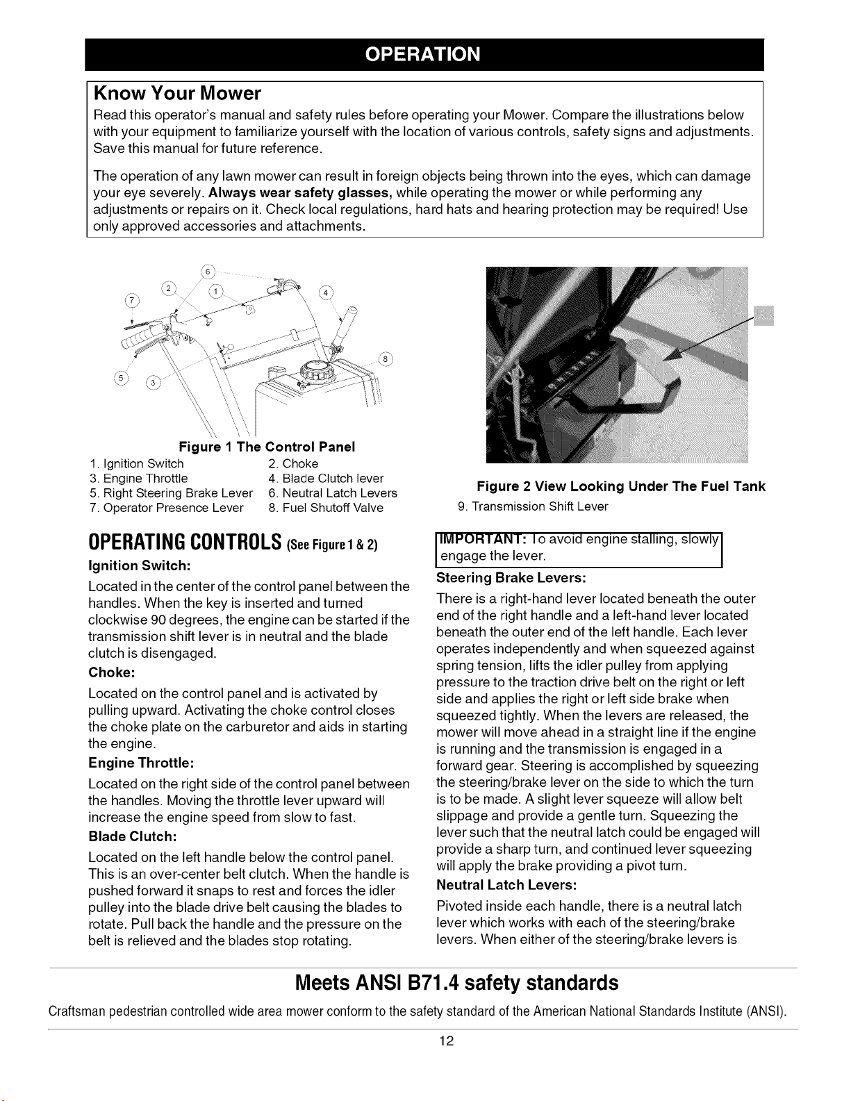
Figure 1 The Control Panel
1. Ignition Switch 2. Choke
3. Engine Throttle 4. Blade Clutch lever
5. Right Steering Brake Lever 6. Neutral Latch Levers
7. Operator Presence Lever 8. Fuel Shutoff Valve
Figure 2 View Looking Under The Fuel Tank
9. Transmission Shift Lever
OPERATINGCONTROLS(seeFigurel& 2)
Ignition Switch:
Located in the center of the control panel between the
handles. When the key is inserted and turned
clockwise 90 degrees, the engine can be started if the
transmission shift lever is in neutral and the blade
clutch is disengaged.
Choke:
Located on the control panel and is activated by
pulling upward. Activating the choke control closes
the choke plate on the carburetor and aids in starting
the engine.
Engine Throttle:
Located on the right side of the control panel between
the handles. Moving the throttle lever upward will
increase the engine speed from slow to fast.
Blade Clutch:
Located on the left handle below the control panel.
This is an over-center belt clutch. When the handle is
pushed forward it snaps to rest and forces the idler
pulley into the blade drive belt causing the blades to
rotate. Pull back the handle and the pressure on the
belt is relieved and the blades stop rotating.
IMPORTANT: Io avoid engine stalling, slowly I
engage the lever. I
Steering Brake Levers:
There is a right-hand lever located beneath the outer
end of the right handle and a left-hand lever located
beneath the outer end of the left handle. Each lever
operates independently and when squeezed against
spring tension, lifts the idler pulley from applying
pressure to the traction drive belt on the right or left
side and applies the right or left side brake when
squeezed tightly. When the levers are released, the
mower will move ahead in a straight line if the engine
is running and the transmission is engaged in a
forward gear. Steering is accomplished by squeezing
the steering/brake lever on the side to which the turn
is to be made. A slight lever squeeze will allow belt
slippage and provide a gentle turn. Squeezing the
lever such that the neutral latch could be engaged will
provide a sharp turn, and continued lever squeezing
will apply the brake providing a pivot turn.
Neutral Latch Levers:
Pivoted inside each handle, there is a neutral latch
lever which works with each of the steering/brake
levers. When either of the steering/brake levers is
Meets ANSI B71.4 safety standards
Craftsmanpedestriancontrolled wide area mower conformto the safety standard ofthe American National Standards Institute (ANSI).
12
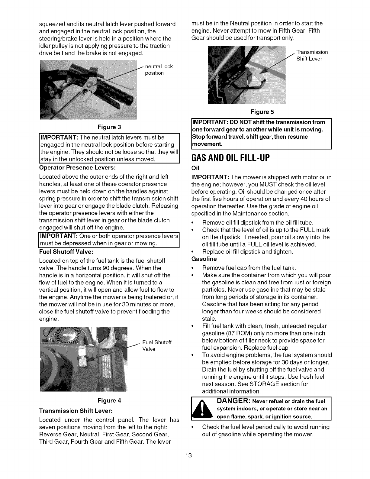
squeezedanditsneutrallatchleverpushedforward
andengagedintheneutrallockposition,the
steering/brakeleverisheldinapositionwherethe
idlerpulleyisnotapplyingpressuretothetraction
drivebeltandthebrakeisnotengaged.
neutral lock
position
must be in the Neutral position in order to start the
engine. Never attempt to mow in Fifth Gear. Fifth
Gear should be used for transport only.
Transmission
Shift Lever
Figure 5
Figure 3
IMPORTANT: The neutral latch levers must be I
engaged in the neutral lock position before starting I
the engine. They should not be loose so that they will
stay n the un ocked post on un ess moved.
Operator Presence Levers:
Located above the outer ends of the right and left
handles, at least one of these operator presence
levers must be held down on the handles against
spring pressure in order to shift the transmission shift
lever into gear or engage the blade clutch. Releasing
the operator presence levers with either the
transmission shift lever in gear or the blade clutch
engaged will shut off the engine.
IMPORTANT: One or both operator presence levers
must be depressed when n gear or mow ng.
Fuel Shutoff Valve:
Located on top of the fuel tank is the fuel shutoff
valve. The handle turns 90 degrees. When the
handle is ina horizontal position, it will shut off the
flow of fuel to the engine. When it is turned to a
vertical position, it will open and allow fuel to flow to
the engine. Anytime the mower is being trailered or, if
the mower will not be in use for 30 minutes or more,
close the fuel shutoff valve to prevent flooding the
engine.
Fuel Shutoff
Valve
Figure 4
Transmission Shift Lever:
Located under the control panel. The lever has
seven positions moving from the left to the right:
Reverse Gear, Neutral, First Gear, Second Gear,
Third Gear, Fourth Gear and Fifth Gear. The lever
IMPORTANT: DO NOT shift the transmission from
one forward gear to another while unit is moving.
Stop forward travel, shift gear, then resume
movement.
GASANDOILFILL-UP
Oil
IMPORTANT: The mower is shipped with motor oil in
the engine; however, you MUST check the oil level
before operating. Oil should be changed once after
the first five hours of operation and every 40 hours of
operation thereafter. Use the grade of engine oil
specified in the Maintenance section.
• Remove oil fill dipstick from the oil fill tube.
• Check that the level of oil is up to the FULL mark
on the dipstick. If needed, pour oil slowly into the
oil fill tube until a FULL oil level is achieved.
• Replace oil fill dipstick and tighten.
Gasoline
• Remove fuel cap from the fuel tank.
• Make sure the container from which you will pour
the gasoline is clean and free from rust or foreign
particles. Never use gasoline that may be stale
from long periods of storage in its container.
Gasoline that has been sitting for any period
longer than four weeks should be considered
stale.
• Fill fuel tank with clean, fresh, unleaded regular
gasoline (87 ROM) only no more than one inch
below bottom of filler neck to provide space for
fuel expansion. Replace fuel cap.
• To avoid engine problems, the fuel system should
be emptied before storage for 30 days or longer.
Drain the fuel by shutting off the fuel valve and
running the engine until it stops. Use fresh fuel
next season. See STORAGE section for
additional information.
_lb DANGER: Never refuel or drain the fuel I
• Check the fuel level periodically to avoid running
system indoors, or operate or store nearan
open flame, spark, or ignition source.
out of gasoline while operating the mower.
I
13
INITIALADJUSTMENTS
1. Disconnect the spark plug wire.
2. Check that all nuts, bolts and screws are tight.
3. Check the tension of the deck drive belts:
a. Remove the deck cover shield and engage
the blade clutch.
b. Make surethe belts clearthe belt guides by
1/8" to 1/4".
c. The tension of the deck drive belts should
be adjusted so that a ten-pound pull
between two pulleys deflects each belt
about 1/2" (See Figure 19 page 19). Do not
overtighten these belts. The blade clutch
should engage with only moderate force.
d. Replace the deck cover shield and
disengage the blade clutch.
,
The tension of the transmission drive belt should
be adjusted so that a five-pound pull between
the engine traction drive pulley and the
transmission drive pulley deflects the belt about
3/16". (See Figure 20 page 20)
,
The two drive wheel belts are self-adjusting.
6.
The steering control rods on each side of the
handle assembly should initially be adjusted so
that there is about a 1/4" to 3/8" space between
the rod and the bottom of the slot inthe neutral
latch lever with the latch in the drive position (See
Figure 6.) To make this adjustment, remove the
large hairpin from the swivel joint at the bottom of
each steering control rod and thread the swivel
joint up or down the rod as needed.
Figure 6
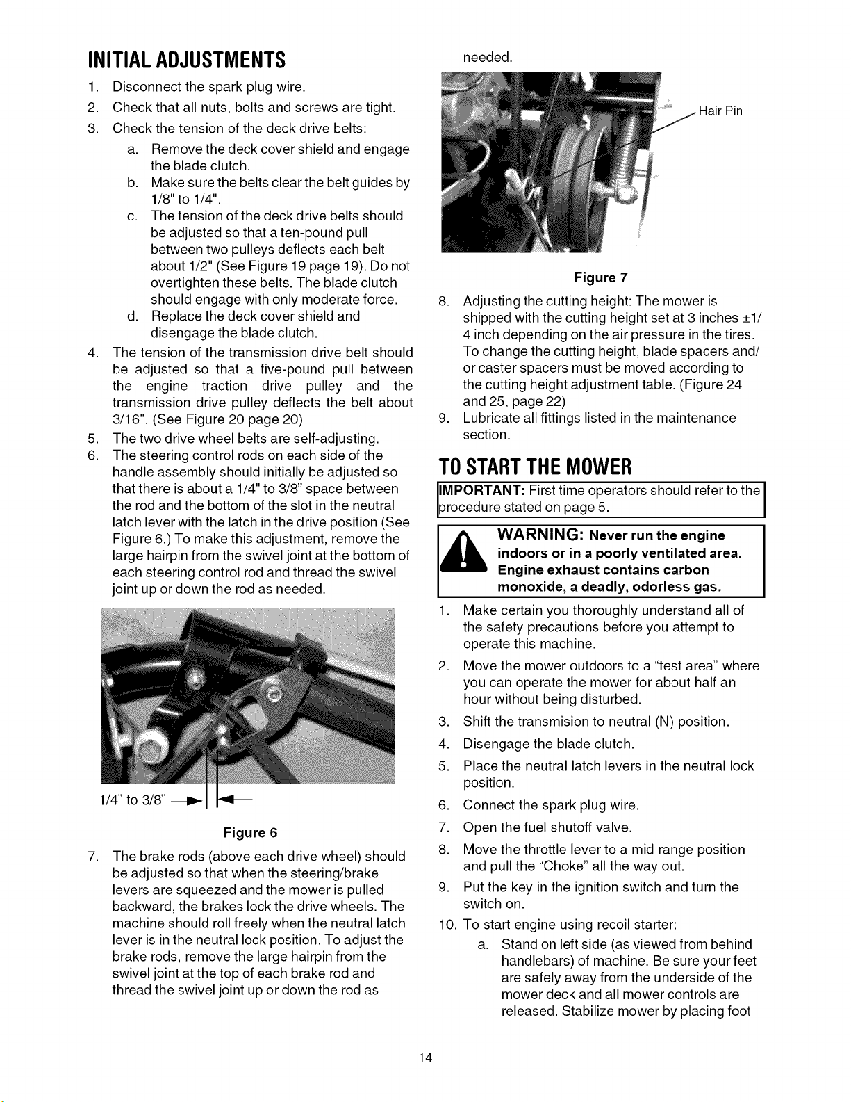
,
The brake rods (above each drive wheel) should
be adjusted so that when the steering/brake
levers are squeezed and the mower is pulled
backward, the brakes lock the drive wheels. The
machine should roll freely when the neutral latch
lever is in the neutral lock position. To adjust the
brake rods, remove the large hairpin from the
swivel joint at the top of each brake rod and
thread the swivel joint up or down the rod as
needed.
Hair Pin
Figure 7
8. Adjusting the cutting height: The mower is
shipped with the cutting height set at 3 inches _+1/
4 inch depending on the air pressure in the tires.
To change the cutting height, blade spacers and/
or caster spacers must be moved according to
the cutting height adjustment table. (Figure 24
and 25, page 22)
9. Lubricate all fittings listed in the maintenance
section.
TOSTARTTHEMOWER
IMPORTANT: First time operators should refer to the
procedure stated on page 5.
indoors or in a poorly ventilated area.
[_ ARNING: Never run the engine
1. Make certain you thoroughly understand all of
2. Move the mower outdoors to a "test area" where
3. Shift the transmision to neutral (N) position.
4. Disengage the blade clutch.
5. Place the neutral latch levers in the neutral lock
6. Connect the spark plug wire.
7. Open the fuel shutoff valve.
8. Move the throttle lever to a mid range position
9. Put the key in the ignition switch and turn the
10. To start engine using recoil starter:
Engine exhaust contains carbon
monoxide, a deadly, odorless gas.
the safety precautions before you attempt to
operate this machine.
you can operate the mower for about half an
hour without being disturbed.
position.
and pull the "Choke" all the way out.
switch on.
a. Stand on left side (as viewed from behind
handlebars) of machine. Be sure your feet
are safely away from the underside of the
mower deck and all mower controls are
released. Stabilize mower by placing foot
14
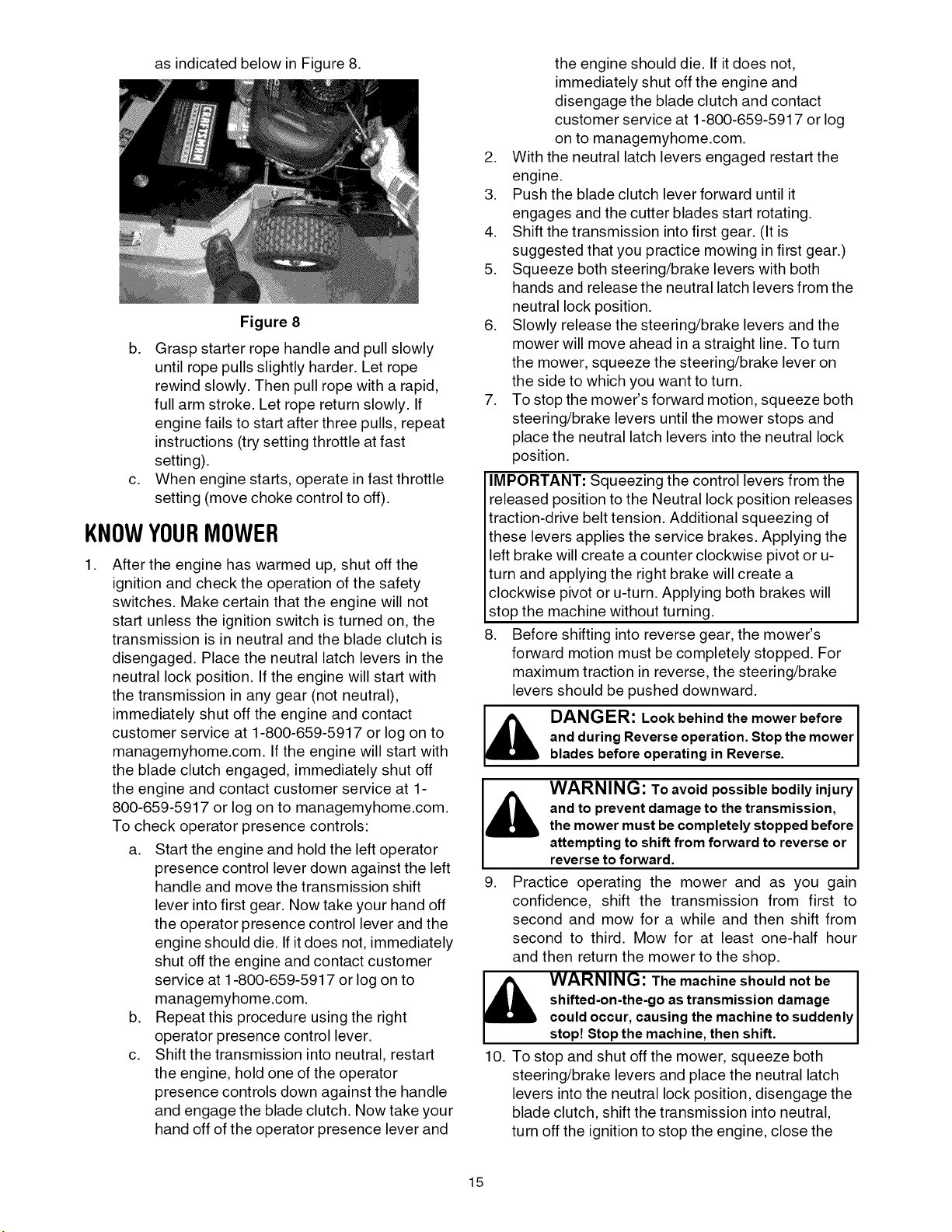
as indicated below in Figure 8.
Figure 8
b. Grasp starter rope handle and pull slowly
until rope pulls slightly harder. Let rope
rewind slowly. Then pull rope with a rapid,
full arm stroke. Let rope return slowly. If
engine fails to start after three pulls, repeat
instructions (try setting throttle at fast
setting).
c. When engine starts, operate in fast throttle
setting (move choke control to off).
KNOWYOURMOWER
,
After the engine has warmed up, shut off the
ignition and check the operation of the safety
switches. Make certain that the engine will not
start unless the ignition switch is turned on, the
transmission is in neutral and the blade clutch is
disengaged. Place the neutral latch levers in the
neutral lock position. If the engine will start with
the transmission in any gear (not neutral),
immediately shut off the engine and contact
customer service at 1-800-659-5917 or log on to
managemyhome.com. If the engine will start with
the blade clutch engaged, immediately shut off
the engine and contact customer service at 1-
800-659-5917 or log on to managemyhome.com.
To check operator presence controls:
a. Start the engine and hold the left operator
presence control lever down against the left
handle and move the transmission shift
lever into first gear. Now take your hand off
the operator presence control lever and the
engine should die. If itdoes not, immediately
shut off the engine and contact customer
service at 1-800-659-5917 or log on to
managemyhome.com.
b. Repeat this procedure using the right
operator presence control lever.
c. Shift the transmission into neutral, restart
the engine, hold one of the operator
presence controls down against the handle
and engage the blade clutch. Now take your
hand off of the operator presence lever and
the engine should die. If it does not,
immediately shut off the engine and
disengage the blade clutch and contact
customer service at 1-800-659-5917 or log
on to managemyhome.com.
2. With the neutral latch levers engaged restart the
engine.
3. Push the blade clutch lever forward until it
engages and the cutter blades start rotating.
4. Shift the transmission into first gear. (It is
suggested that you practice mowing in first gear.)
5. Squeeze both steering/brake levers with both
hands and release the neutral latch levers from the
neutral lock position.
6. Slowly release the steering/brake levers and the
mower will move ahead in a straight line. To turn
the mower, squeeze the steering/brake lever on
the side to which you want to turn.
7. To stop the mower's forward motion, squeeze both
steering/brake levers until the mower stops and
place the neutral latch levers into the neutral lock
position.
IMPORTANT: Squeezing the control levers from the
released position to the Neutral lock position releases
traction-drive belt tension. Additional squeezing of
these levers applies the service brakes. Applying the
left brake will create a counter clockwise pivot or u-
turn and applying the right brake will create a
clockwise pivot or u-turn. Applying both brakes will
stop the machine without turning.
8. Before shifting into reverse gear, the mower's
forward motion must be completely stopped. For
maximum traction in reverse, the steering/brake
levers should be pushed downward.
and during Reverse operation.Stopthe mower
DANGER: Look behind the mower before
bladesbefore operating in Reverse.
and to prevent damageto the transmission,
the mower must be completely stopped before
I_, ARNING: Toavoid possible bodily injury
attempting to shift from forward to reverse or
reverseto forward.
9. Practice operating the mower and as you gain
confidence, shift the transmission from first to
second and mow for a while and then shift from
second to third. Mow for at least one-half hour
and then return the mower to the shop.
shifted-on-the-go as transmission damage
_lb WARNING: The machine should not be I
could occur, causing the machineto suddenly
stop Stopthe mach ne, then sh ft.
10. To stop and shut off the mower, squeeze both
steering/brake levers and place the neutral latch
levers into the neutral lock position, disengage the
blade clutch, shift the transmission into neutral,
turn off the ignition to stop the engine, close the
I
15
fuel shutoff valve and disconnect the spark plug
wire.
11. Check that all nuts, bolts and screws are still
tight.
12. Check, and adjust if necessary, the tension of the
deck drive belts and the transmission drive belt
as described in items 3 and 4 of the Initial
Adjustment section.
13. Readjust the steering control rods and the brake
rods. They may require frequent adjustment until
the belts and brake bands have properly seated.
These adjustments are described in items 6 and
7 of the Initial Adjustment section.
14. After the first full day of mowing, all nuts, bolt and
screws should be rechecked for proper tightness
and the belts should be rechecked for proper
tension.
USINGTHEMOWER
MPORTANT: First time operators should refer to the I
rocedure stated on page 5. I
1. Be sure area is clear of rocks, sticks, toys, wire,
or other objects that could be thrown by the
mower. Survey the entire area to be mowed.
Make sure that the accessories and attachments
would be suitable for use on the terrain.
2. With the neutral latches locked and the operator
presence levers depressed, select a mowing
speed. (a slower speed is suggested during first
time use.)
3. Engage the mower by pushing the blade clutch
lever forward until it locks.
4. Squeeze the steering control levers and release
the neutral latches.
5. Slowly release the steering control levers and the
mower should go straight ahead.
6. To operate in Reverse, look behind and down
before backing up to be sure the path is clear.
7. Be aware of the mower discharge and do not
point it at anyone, or onto sidewalks and streets.
8. Use care when approaching blind corners,
shrubs, trees or other objects that could obstruct
vision.
9. To mow grass and produce a striped pattern:
a. Pick a point on the opposite side of the
area to be mowed (post, tree, shrub, etc).
b. Ifon a hillside, start at the bottom so that
the turns are uphill rather than downhill.
c. Align the mower so as to head directly
toward the object on the far side.
d. Slowly increase the speed of the machine
to match cutting conditions, terrain, and
operator familiarity with the controls and
keep the machine headed directly toward
the alignment object. Do not go fast as to
reduce cut quality or to be uncomfortable in
controlling the speed and direction of the
machine.
e. When approaching the other end of a strip,
slow down or stop before turning. A U-turn
is recommended.
f. To prevent rutting or grooving of the turf,
change the direction that the strips are
mowed by approximately 45 degrees the
next and each subsequent time that the
area is mowed.
g. Ifthe grass is repeatedly mowed in the
same direction, it will be "trained" so that
the Striped appearance is more
pronounced and longer lasting. Grooving
of the turf from the tires will occur.
10.
For empting material collection systems or for
any other operation involving the mower deck,
before leaving the operator station:
• shut off the mower deck.
• place the transmission in neutral.
• latch the neutral locks.
• shut off the engine.
• apply wheel chocks.
TRANSPORTINGMOWER
1. If ramps are used, be sure they are secured to
the trailer, truck bed, etc. and are designed for
the application.
2. The mower should be pushed or pulled onto or off
the trailer, truck bed, etc., never try to drive iton.
3. Turn the fuel valve off.
4. Secure mower with chocks, straps, etc.
5. Make sure accessories and attachments are
secured or removed.
16
GENERALRECOMMENDATIONS
people operate or servicethe mower.
WARNING: Never let children or untrained
• Always observe safety rules when performing any
type of maintenance on the mower.
• The warranty on this lawn mower does not cover
items that have been subjected to operator abuse
or negligence. To receive full value from the
warranty, operator must maintain the equipment as
instructed in this manual.
• Changing of engine-governed speed will void
engine warranty.
• Periodically check all fasteners and make sure they
are tight.
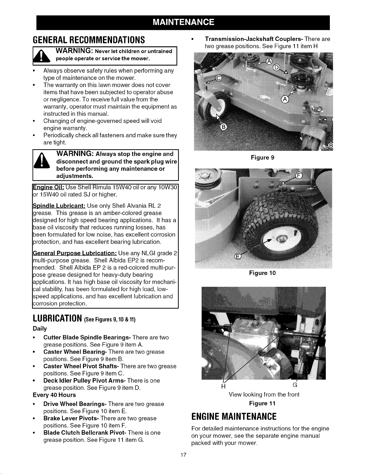
Transmission-Jackshaft Couplers- There are
two grease positions. See Figure 11 item H
disconnect and ground the spark plug wire
J& ARNING: Always stop the engine and I
Engine Oil: Use Shell Rimula 15W40 oil or any 10W30
or 15W40 oil rated SJ or higher.
Spindle Lubricant: Use only Shell Alvania RL 2
grease. This grease is an amber-colored grease
designed for high speed bearing applications. It has a
base oil viscosity that reduces running losses, has
been formulated for low noise, has excellent corrosion
_rotection, and has excellent bearing lubrication.
3eneral Purpose Lubrication: Use any NLGI grade 2
multi-purpose grease. Shell Albida EP2 is recom-
mended. Shell Albida EP 2 is a red-colored multi-pur-
pose grease designed for heavy-duty bearing
_pplications. It has high base oil viscosity for mechani-
;al stability, has been formulated for high load, low-
speed applications, and has excellent lubrication and
;orrosion protection.
before performing any maintenance oradjustments.
LUBRICATION(seeFigures9,10 & 11)
Daily
• Cutter Blade Spindle Bearings- There are two
grease positions. See Figure 9 item A.
• Caster Wheel Bearing- There are two grease
positions. See Figure 9 item B.
• Caster Wheel Pivot Shafts- There are two grease
positions. See Figure 9 item C.
• Deck Idler Pulley Pivot Arms- There is one
grease position. See Figure 9 item D.
Every 40 Hours
• Drive Wheel Bearings- There are two grease
positions. See Figure 10 item E.
• Brake Lever Pivots- There are two grease
positions. See Figure 10 item F.
• Blade Clutch Bellcrank Pivot- There is one
grease position. See Figure 11 item G.
Figure 9
Figure 10
H G
View looking from the front
Figure 11
ENGINEMAINTENANCE
For detailed maintenance instructions for the engine
on your mower, see the separate engine manual
packed with your mower.
17
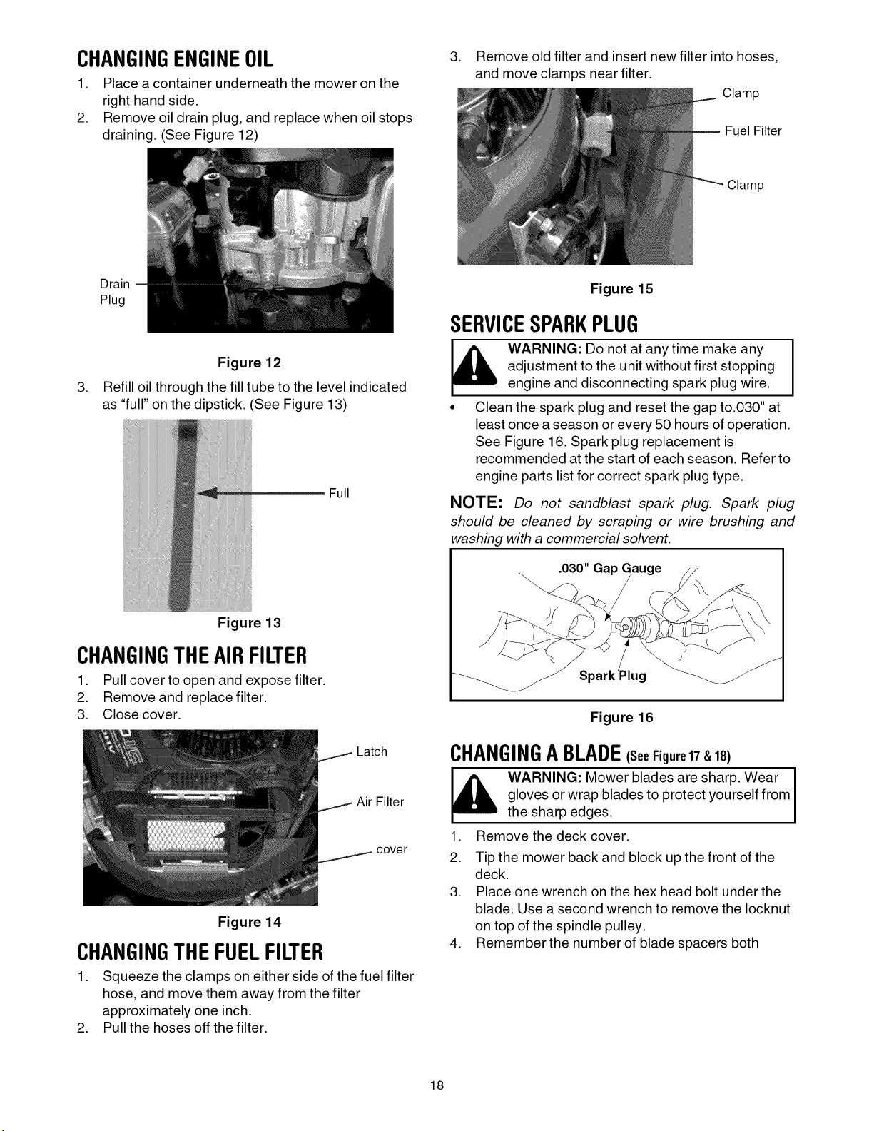
CHANGINGENGINEOIL
1. Place a container underneath the mower on the
right hand side.
2. Remove oil drain plug, and replace when oil stops
draining. (See Figure 12)
, Remove old filter and insert new filter into hoses,
and move clamps near filter.
Clamp
Fuel Filter
Clamp
Drain
Plug
Figure 12
,
Refill oil through the fill tube to the level indicated
as "full" on the dipstick. (See Figure 13)
Full
Figure 13
CHANGINGTHEAIRFILTER
1. Pull cover to open and expose filter.
2. Remove and replace filter.
3. Close cover.
Figure 15
SERVICESPARKPLUG
adjustment to the unit without first stopping
WARNING: Do not at any time make any
engine and disconnecting spark plug wire.
• Clean the spark plug and reset the gap to.030" at
least once a season or every 50 hours of operation.
See Figure 16. Spark plug replacement is
recommended at the start of each season. Refer to
engine parts list for correct spark plug type.
NOTE: Do not sandblast spark plug. Spark plug
should be cleaned by scraping or wire brushing and
washing with a commercial solvent.
.030" Ga
Plug
Figure 16
Latch
Air Filter
cover
Figure 14
CHANGINGTHEFUELFILTER
1. Squeeze the clamps on either side of the fuel filter
hose, and move them away from the filter
approximately one inch.
2. Pull the hoses off the filter.
CHANGINGABLADE€seeFigure17&18)
gloves or wrap blades to protect yourself from
WARNING: Mower blades are sharp. Wear I
the sharp edges.
1. Remove the deck cover.
2. Tip the mower back and block up the front of the
deck.
3. Place one wrench on the hex head bolt under the
blade. Use a second wrench to remove the Iocknut
on top of the spindle pulley.
4. Remember the number of blade spacers both
18
I
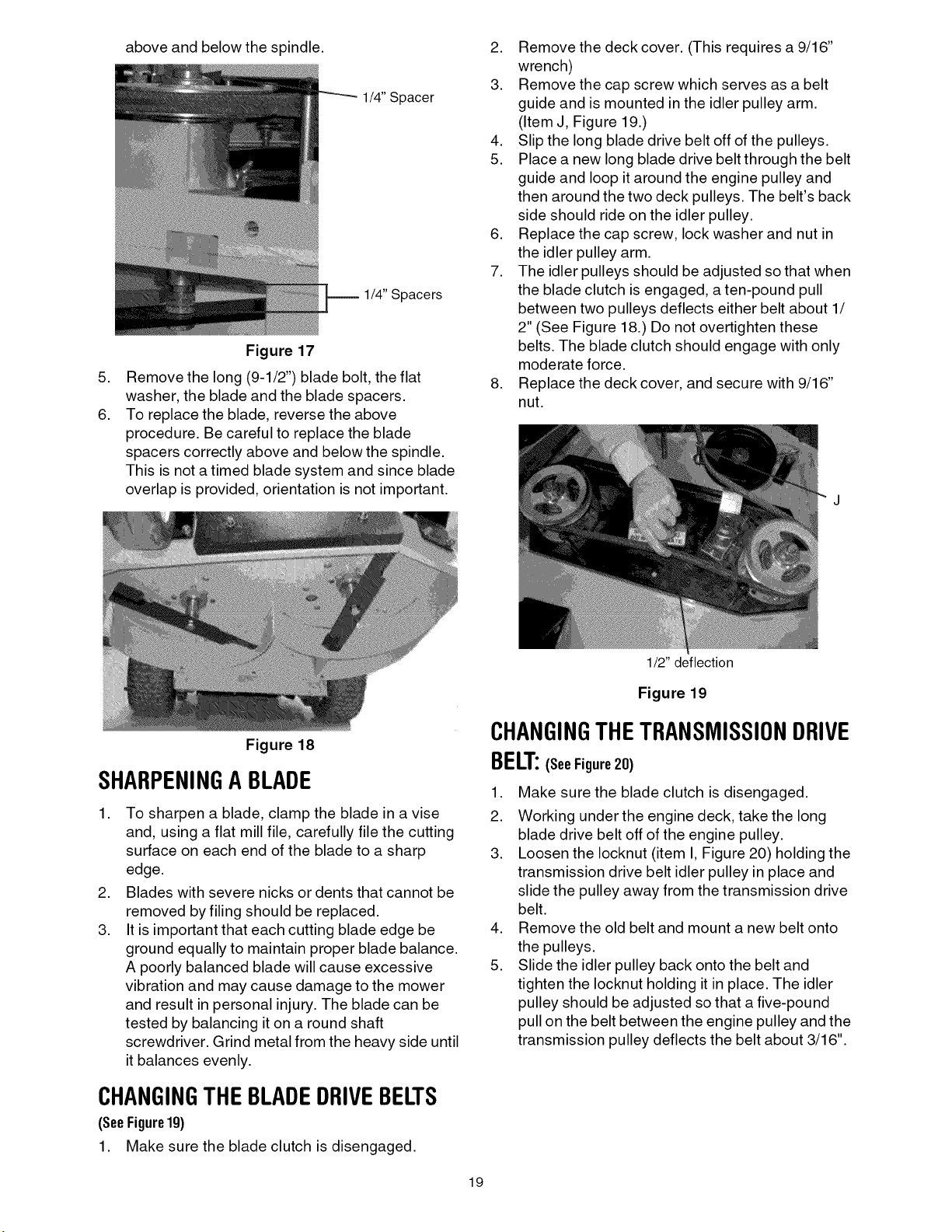
above and below the spindle.
1/4" Spacer
1/4" Spacers
Figure 17
,
Remove the long (9-1/2") blade bolt, the flat
washer, the blade and the blade spacers.
6.
To replace the blade, reverse the above
procedure. Be careful to replace the blade
spacers correctly above and below the spindle.
This is not a timed blade system and since blade
overlap is provided, orientation is not important.
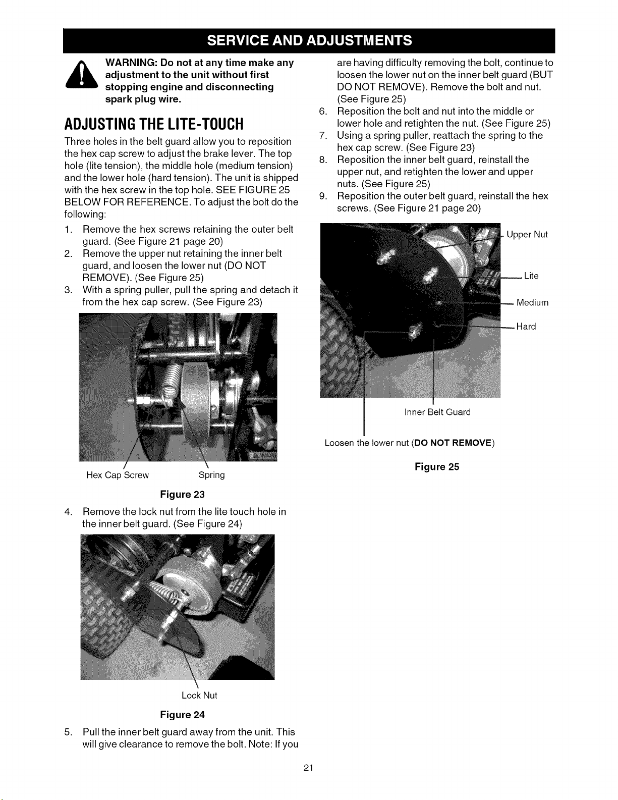
2. Remove the deck cover. (This requires a 9/16"
wrench)
3. Remove the cap screw which serves as a belt
guide and is mounted in the idler pulley arm.
(Item J, Figure 19.)
4. Slip the long blade drive belt off of the pulleys.
5. Place a new long blade drive belt through the belt
guide and loop it around the engine pulley and
then around the two deck pulleys. The belt's back
side should ride on the idler pulley.
6. Replace the cap screw, lock washer and nut in
the idler pulley arm.
7. The idler pulleys should be adjusted so that when
the blade clutch is engaged, a ten-pound pull
between two pulleys deflects either belt about 1/
2" (See Figure 18.) Do not overtighten these
belts. The blade clutch should engage with only
moderate force.
8. Replace the deck cover, and secure with 9/16"
nut.
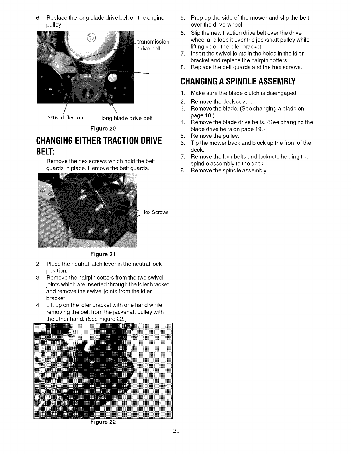
Figure 18
SHARPENINGA BLADE
,
To sharpen a blade, clamp the blade in a vise
and, using a flat mill file, carefully file the cutting
surface on each end of the blade to a sharp
edge.
,
Blades with severe nicks or dents that cannot be
removed by filing should be replaced.
3.
It is important that each cutting blade edge be
ground equally to maintain proper blade balance.
A poorly balanced blade will cause excessive
vibration and may cause damage to the mower
and result in personal injury. The blade can be
tested by balancing it on a round shaft
screwdriver. Grind metal from the heavy side until
it balances evenly.
CHANGINGTHEBLADEDRIVEBELTS
(SeeFigurelg)
1. Make sure the blade clutch is disengaged.
1/2" deflection
Figure 19
CHANGINGTHETRANSMISSIONDRIVE
BELT:(SeeFigure20)
1. Make sure the blade clutch is disengaged.
2. Working under the engine deck, take the long
blade drive belt off of the engine pulley.
3. Loosen the Iocknut (item I, Figure 20) holding the
transmission drive belt idler pulley in place and
slide the pulley away from the transmission drive
belt.
4. Remove the old belt and mount a new belt onto
the pulleys.
5. Slide the idler pulley back onto the belt and
tighten the Iocknut holding it in place. The idler
pulley should be adjusted so that a five-pound
pull on the belt between the engine pulley and the
transmission pulley deflects the belt about 3/16".
19
,
Replace the long blade drive belt on the engine
pulley.
. transmission
drive belt
3/16" deflection
long blade drive belt
Figure 20
CHANGINGEITHERTRACTIONDRIVE
BELT:
1. Remove the hex screws which hold the belt
guards in place. Remove the belt guards.
5. Prop up the side of the mower and slip the belt
over the drive wheel.
6. Slip the new traction drive belt over the drive
wheel and loop it over the jackshaft pulley while
lifting up on the idler bracket.
7. Insert the swivel joints in the holes in the idler
bracket and replace the hairpin cotters.
8. Replace the belt guards and the hex screws.
CHANGINGASPINDLEASSEMBLY
1. Make sure the blade clutch is disengaged.
2. Remove the deck cover.
3. Remove the blade. (See changing a blade on
page 18.)
4. Remove the blade drive belts. (See changing the
blade drive belts on page 19.)
5. Remove the pulley.
6. Tip the mower back and block up the front of the
deck.
7. Remove the four bolts and Iocknuts holding the
spindle assembly to the deck.
8. Remove the spindle assembly.
Screws
Figure 21
2. Place the neutral latch lever in the neutral lock
position.
3. Remove the hairpin cotters from the two swivel
joints which are inserted through the idler bracket
and remove the swivel joints from the idler
bracket.
4. Lift up on the idler bracket with one hand while
removing the belt from the jackshaft pulley with
the other hand. (See Figure 22.)
Figure 22
20
WARNING: Do not at any time make any
adjustment to the unit without first
stopping engine and disconnecting
spark plug wire.
ADJUSTINGTHELITE-TOUCH
Three holes in the belt guard allow you to reposition
the hex cap screw to adjust the brake lever. The top
hole (lite tension), the middle hole (medium tension)
and the lower hole (hard tension). The unit is shipped
with the hex screw in the top hole. SEE FIGURE 25
BELOW FOR REFERENCE. To adjust the bolt do the
following:
1. Remove the hex screws retaining the outer belt
guard. (See Figure 21 page 20)
2. Remove the upper nut retaining the inner belt
guard, and loosen the lower nut (DO NOT
REMOVE). (See Figure 25)
3. With a spring puller, pull the spring and detach it
from the hex cap screw. (See Figure 23)
are having difficulty removing the bolt, continue to
loosen the lower nut on the inner belt guard (BUT
DO NOT REMOVE). Remove the bolt and nut.
(See Figure 25)
6. Reposition the bolt and nut into the middle or
lower hole and retighten the nut. (See Figure 25)
7. Using a spring puller, reattach the spring to the
hex cap screw. (See Figure 23)
8. Reposition the inner belt guard, reinstall the
upper nut, and retighten the lower and upper
nuts. (See Figure 25)
9. Reposition the outer belt guard, reinstall the hex
screws. (See Figure 21 page 20)
Upper Nut
Medium
Hex Cap Screw Spring
Figure 23
,
Remove the lock nut from the lite touch hole in
the inner belt guard. (See Figure 24)
Lock Nut
Inner Belt Guard
Loosenthe lower nut (DO NOT REMOVE)
Figure 25
Figure 24
,
Pull the inner belt guard away from the unit. This
will give clearance to remove the bolt. Note: Ifyou
21
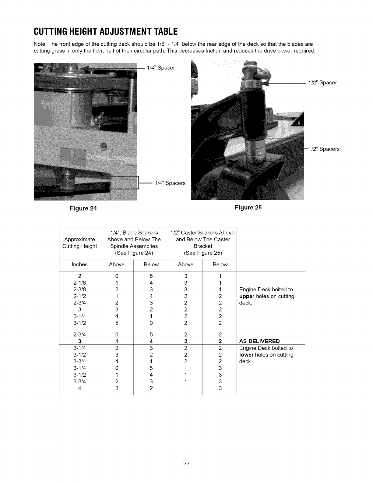
CUTTINGHEIGHTADJUSTMENTTABLE
Note: The front edge of the cutting deck should be 1/8" - 1/4" below the rear edge of the deck so that the blades are
cutting grass in only the front half of their circular path. This decreases friction and reduces the drive power required.
1/4" Spacer
1/4" Spacers
Figure 24 Figure 25
1/2" Spacer
1/2" Spacers
1/4": Blade Spacers
Approximate and Below The Caster
Cutting Height Bracket
Inches Above Below
2
2-1/8
2-3/8
2-1/2
2-3/4
3
3-1/4
3-1/2
2-3/4
3
3-1/4
3-1/2
3-3/4
3-1/4
3-1/2
3-3/4
4
Above and Below The
Spindle Assemblies
(See Figure 24)
Above Below
0 5
1 4
2 3
1 4
2 3
3 2
4 1
5 0
0 5
1 4
2 3
3 2
4 1
0 5
1 4
2 3
3 2
1/2" Caster Spacers Above
(See Figure 25)
3
3
3
2
2
2
2
2
2
2
2
2
2
1
1
1
1
1
1
1
2
2
2
2
2
2
2
2
2
2
3
3
3
3
Engine Deck bolted to
upper holes on cutting
deck.
AS DELIVERED
Engine Deck bolted to
lower holes on cutting
deck.
22
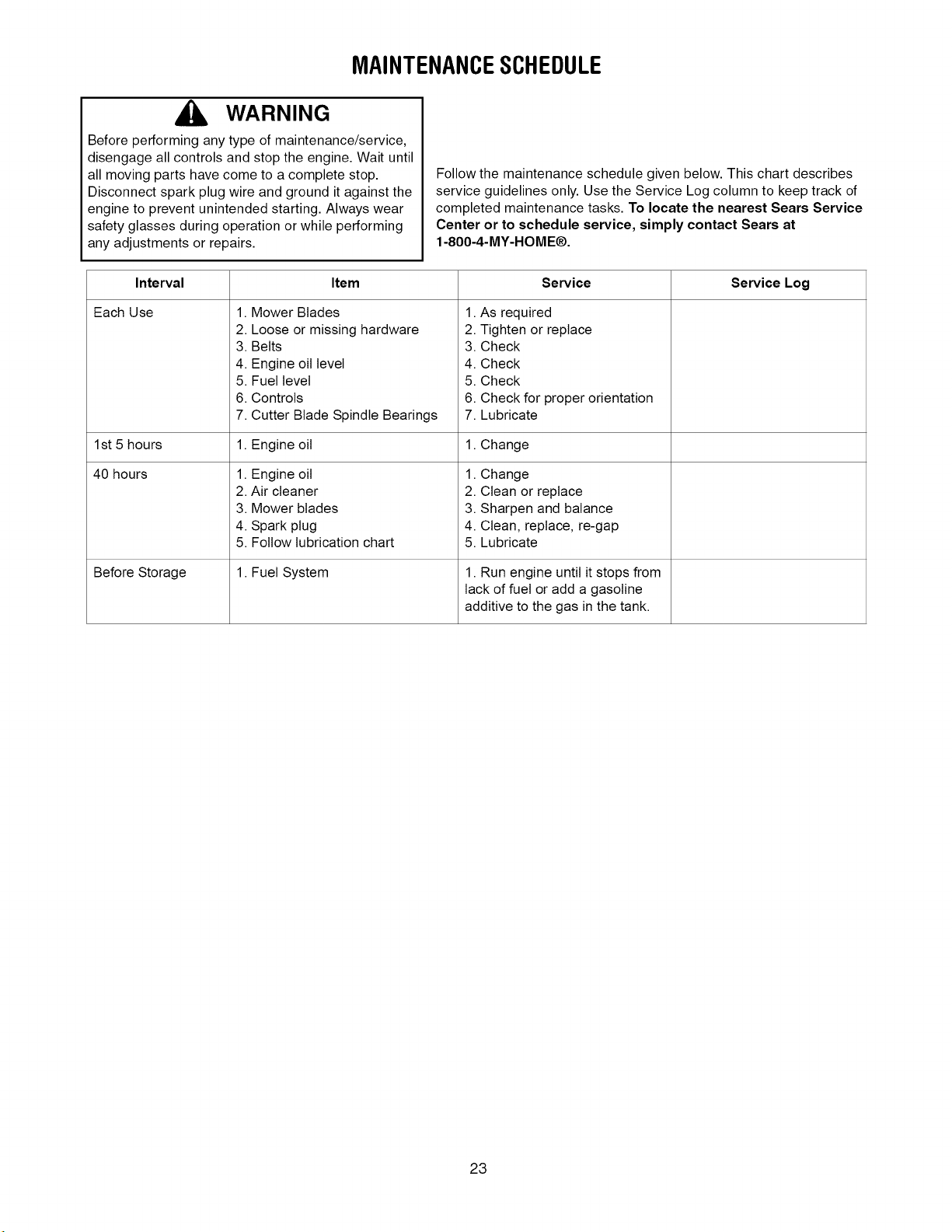
MAINTENANCESCHEDULE
WARNING
Before performing any type of maintenance/service,
disengage all controls and stop the engine. Wait until
all moving parts have come to a complete stop.
Disconnect spark plug wire and ground it against the
engine to prevent unintended starting. Always wear
safety glasses during operation or while performing
any adjustments or repairs.
Follow the maintenance schedule given below. This chart describes
service guidelines only. Use the Service Log column to keep track of
completed maintenance tasks. To locate the nearest Sears Service
Center or to schedule service, simply contact Sears at
1-800-4-MY-HOME®.
Interval Service Log
Each Use 1.
1st 5 hours 1.
40 hours
Before Storage
Mower Blades 1. As required
2.
Loose or missing hardware 2. Tighten or replace
3.
Belts 3. Check
4.
Engine oil level 4. Check
5.
Fuel level 5. Check
6.
Controls 6. Check for proper orientation
7.
Cutter Blade Spindle Bearings 7. Lubricate
Engine oil 1. Change
1.
Engine oil 1. Change
2.
Air cleaner 2. Clean or replace
3.
Mower blades 3. Sharpen and balance
4.
Spark plug 4. Clean, replace, re-gap
5.
Follow lubrication chart 5. Lubricate
• Fuel System 1. Run engine until it stops from
Item Service
lack of fuel or add a gasoline
additive to the gas in the tank.
23
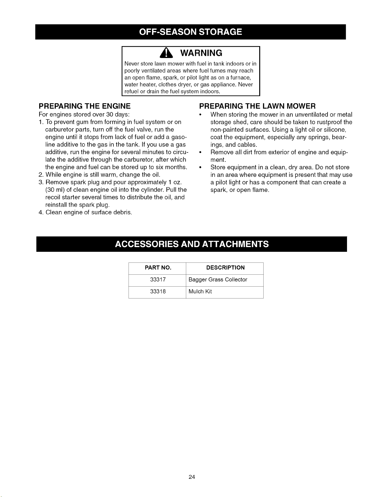
WARNING
Never store lawn mowerwith fuel intank indoorsor in
poorly ventilated areas where fuelfumes may reach
an open flame, spark, or pilot light as on a furnace,
water heater,clothes dryer, or gas appliance. Never
refuel or drain thefuel system indoors.
PREPARING THE ENGINE
For engines stored over 30 days:
1. To prevent gum from forming infuel system or on
carburetor parts, turn off the fuel valve, run the
engine until it stops from lack of fuel or add a gaso-
line additive to the gas in the tank. If you use a gas
additive, run the engine for several minutes to circu-
late the additive through the carburetor, after which
the engine and fuel can be stored up to six months.
2. While engine is still warm, change the oil.
3. Remove spark plug and pour approximately 1 oz.
(30 ml) of clean engine oil into the cylinder. Pull the
recoil starter several times to distribute the oil, and
reinstall the spark plug.
4. Clean engine of surface debris.
PART NO. DESCRIPTION
33317 Bagger Grass Collector
33318 Mulch Kit
PREPARING THE LAWN MOWER
• When storing the mower in an unventilated or metal
storage shed, care should be taken to rustproof the
non-painted surfaces. Using a light oil or silicone,
coat the equipment, especially any springs, bear-
ings, and cables.
• Remove all dirt from exterior of engine and equip-
ment.
• Store equipment in a clean, dry area. Do not store
in an area where equipment is present that may use
a pilot light or has a component that can create a
spark, or open flame.
24
WARNING
Before performing any type of maintenance/service, disengage all
controls and stop the engine. Wait until all moving parts have come
to a complete stop.
Disconnect spark plug wire and ground it against the engine to pre-
NEED MORE HELP?
Y_ [ _h/d the _ we_ _t _ _oe o_ _a_agemyhomeocom _ _o_ f_ee_
o F_d tMs and a_.[you_ otl_e_ product manuals online.
- Get a_swers from our team of hol_le experts,
o Get a personalized maintenance plan for your home,
, F;I_ il_folmat_or_ and tools to help w_th home project,
vent unintended starting. Always wear safety glasses during opera-
tion or while performing any adjustments or repairs.
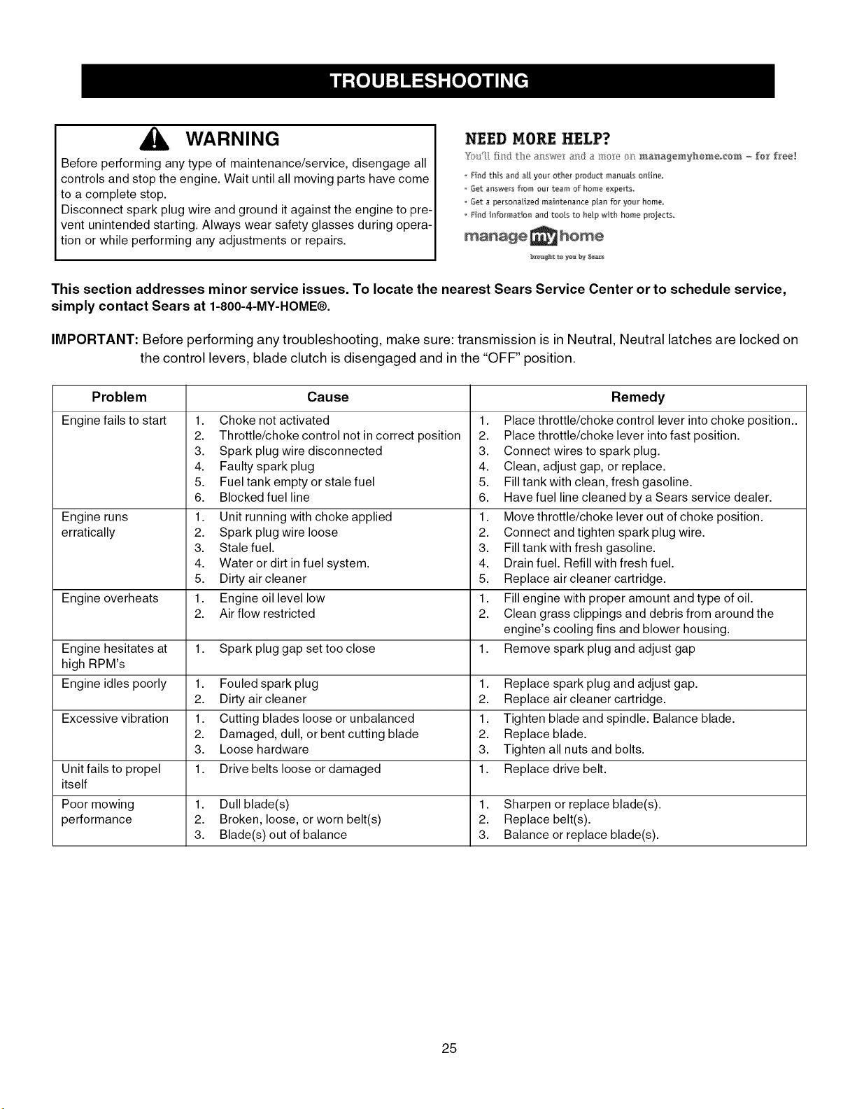
This section addresses minor service issues. To locate the nearest Sears Service Center or to schedule service,
simply contact Sears at 1-800-4-MY-HOME®.
IMPORTANT: Before performing any troubleshooting, make sure: transmission is in Neutral, Neutral latches are locked on
the control levers, blade clutch is disengaged and in the "OFF" position.
Problem Cause Remedy
Enginefails to start
Engine runs
erratically
Engine overheats
Engine hesitates at 1. Spark plug gap set too close 1.
high RPM's
Engine idles poorly 1. Fouled spark plug 1. Replace spark plug and adjust gap.
Excessive vibration 1. Cutting blades loose or unbalanced 1. Tighten blade and spindle. Balance blade.
Unit fails to propel 1. Drive belts loose or damaged 1. Replace drive belt.
itself
Poor mowing 1. Dull blade(s) 1. Sharpen or replace blade(s).
performance 2. Broken, loose, or worn belt(s) 2. Replace belt(s).
1. Choke not activated
2. Throttle/choke control not in correct position
3. Spark plug wire disconnected
4. Faulty spark plug
5. Fuel tank empty or stale fuel
6. Blocked fuel line
1. Unit running with choke applied
2. Spark plug wire loose
3. Stale fuel.
4. Water or dirt infuel system.
5. Dirty air cleaner
1. Engine oil level low
2. Air flow restricted
1. Place throttle/choke control lever into choke position..
2. Place throttle/choke lever into fast position.
3. Connect wires to spark plug.
4. Clean, adjust gap, or replace.
5. Fill tank with clean, fresh gasoline.
6. Have fuel line cleaned by a Sears service dealer.
1. Move throttle/choke lever out of choke position.
2. Connect and tighten spark plug wire.
3. Fill tank with fresh gasoline.
4. Drain fuel. Refill with fresh fuel.
5. Replace air cleaner cartridge.
1. Fill engine with proper amount and type of oil.
2. Clean grass clippings and debris from around the
engine's cooling fins and blower housing.
Remove spark plug and adjust gap
2. Dirty air cleaner 2. Replace air cleaner cartridge.
2. Damaged, dull, or bent cutting blade 2. Replace blade.
3. Loose hardware 3. Tighten all nuts and bolts.
3. Blade(s) out of balance 3. Balance or replace blade(s).
25
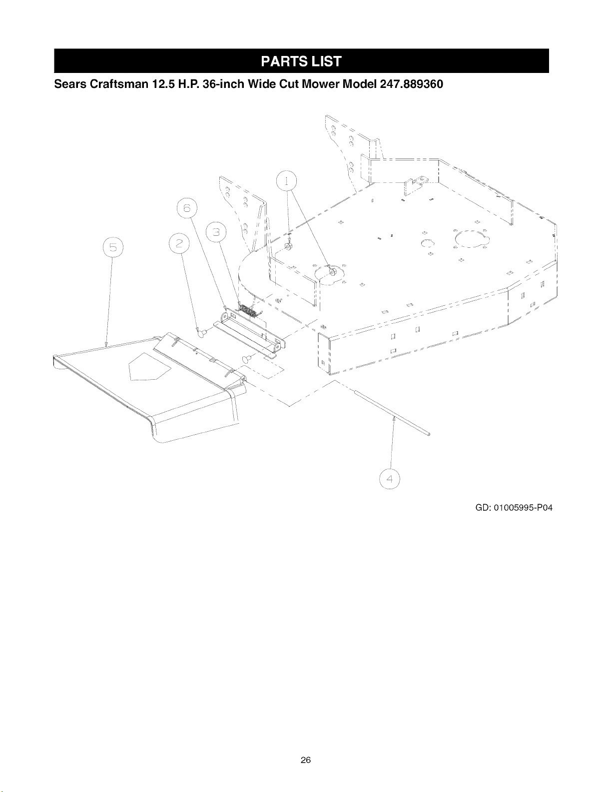
Sears Craftsman 12.5 H.P. 36-inch Wide Cut Mower Model 247.889360
\ •
26
GD: 01005995-P04

Sears Craftsman 12.5 H.P. 36-inch Wide Cut Mower Model 247.889360
Ref. No.
1.
2.
3.
4.
5.
6.
Part No.
712-04065
01000643
01003253
01003254
01006693
01009884
Part Description
Hex Nut, 3/8-16, Flange Lock
Carriage Bolt 3/8-16 x 1.00
Torsion Spring
Chute Deflector Rod
Deflector Chute
Deflector Chute Bracket
Qty.
2
2
1
1
1
1
NOTE: For painted parts, please refer to the list of color codes below. Please add the applicable color code, wherever needed,
to the part number to order a replacement part. For instance, if a part, numbered 0100-xxxx, is painted Sears yellow, the part
number to order would be 0100-xxxx-04028.
Sears Yellow: 04028
Powder Black: 0637
27
 Loading...