

Craftsman 247888520 Owner’s Manual
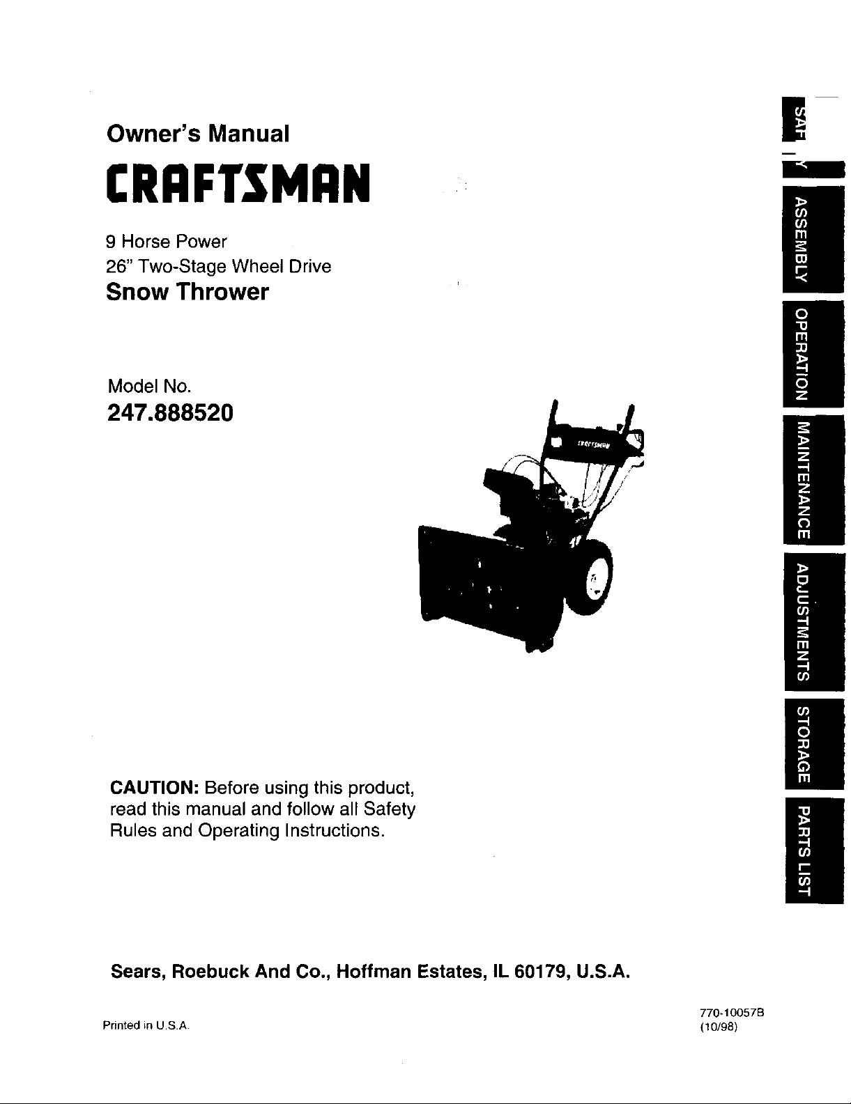
Owner's Manual
CRRFTSMRN
9 Horse Power
|
26" Two-Stage Wheel Drive
Snow Thrower
Model No.
247.888520
MR
CAUTION: Before using this product,
read this manual and follow all Safety
Rules and Operating Instructions.
Sears, Roebuck And Co., Hoffman Estates, IL 60179, U.S.A.
770-10057B
Printed in USA. (10/98)
Content Page
Warranty Information ......................................... 2
Safe Operation Practices ................................... 3
Assembly ........................................................... 6
Operation ........................................................... 12
Maintenance ...................................................... 17
Two -Year Warranty on Craftsman Snow Thrower
For two years from the date of purchase, when this Craftsman Snow Thrower is maintained, lubricated and tuned
up according to the instructions in the owner's manual, Sears will repair, free of charge, any defect in material
and workmanship.
If this Craftsman snow thrower is used for commercial or rental purposes, this warranty applies for only 30 days
from the date of purchase.
This warranty does not cover:
Expendable items which become worn during normal use, such as skid shoes, shave plate and spark
plugs.
Repairs necessary because of operator abuse or negligence, including bent crankshafts and the failure to
maintain the equipment according to the instructions contained in the owner's manual.
WARRANTY SERVICE IS AVAILABLEBYRETURNING THE CRAFTSMAN SNOW THROWER TOTHE NEAREST
SEARS SERVICE CENTER/DEPARTMENT INTHE UNITED STATES.
This warranty applies only while this product is in use in the United States.
This warrantygives you specific legal rights and you may also have other rightswhich may varyfrom statetostate.
SEARS, ROEBUCKAND CO., D/817WA, HOFFMAN ESTATES,IL60179
Content Page
Service & Adjustment ......................................... 20
Off-Season Storage ........................................... 25
Trouble-Shooting ............................................... 26
Accessories ....................................................... 27
Horsepower: ......................... 9
Engine Oil ............................. SAE 5W30 oil
Fuel Capacity: ....................... 1 gallon
Spark Plug: ........................... RJ-19LM
Engine:.................................. 143.999005
Model Number 247.888520
Serial Number ...........................................................
Date of Purchase ......................................................
Record both serial number and date ofpurchase and
keep in a safe place for future reference.
This symbol points out important safety instructions which,ifnotfollowed, couldendangerthe
personalsafety and/or propertyofyourselfand others. Read and followall instructionsinthis manual
beforeattemptingtooperate yoursnowthrower. Failure tocomplywiththese instructionsmay result in
personalinjury.When you see thissymbol--heed its warning.
Your snow throwerwasbuilt to be operated according to the rules for safe operation in this
DANGER: operator can result in serious injury. Ifyou violate any of these rules,you may cause serious
,_ manual. As withany type of power equipment, carelessness orerror on the part of the
injury to yourself or others.
This unit is equipped with an internal combustion engine and should not be used on or near any unimproved
forest-covered, brush-covered or grass-covered land unless the engine's exhaust system is equipped with a
spark arrester meeting applicable local or state laws (ifany). If a spark arrester is used, it should be
maintained in effective working order by the operator.
In the State of California the above is required by law (Section 4442 of the California Public Resources
Code). Other states may have similar laws. Federal laws apply on federal lands. A spark arrester for the
muffler is available through your nearest Sears Authorized Service Center (See the REPAIR PARTS section
of this manuaL.)
The engine exhaust from this product contains chemicals known to the state of California to cause cancer,
birth defects or other reproductive harm,
TRAINING
Read this owner's guide carefully in itsentirety before
attempting to assemble or operate this machine. Be
completely familiar with the controls and the proper
use of this machine before operating it. Keep this
manual in a safe place for future and regular
reference and for ordering replacement parts.
Never allow children under 14 years old to operate a
snow thrower. Children 14 years old and over should
only operate a snow thrower under close parental
supervision. Only persons well acquainted with these
rules of safe operation should be allowed to use your
snow thrower.
No one should operate this unit while intoxicated or
while taking medication that impairs the senses or
reactions.
Keep the area of operation clear of all persons,
especially small children and pets.
Exercise caution to avoid slipping orfalling, especially
when operating in reverse.
PREPARATION
Thoroughly inspect the area where the equipment is
to be used and remove all door mats, sleds, boards,
wires and other foreign objects.
Do not operate equipment without wearing adequate
outer garments for winter. Do not wear jewelry, long
scarfs or other loose clothing which could become
entangled in moving parts. Wear tootwear which will
improve footing on slippery surfaces.
Before working with gasoline, extinguish all cigarettes
and other sources of ignition. Check the fuel before
starting the engine. Gasoline is an extremely
flammable fuel. Do not fill the gasoline tank indoors,
while the engine is running, or until engine has been
allowed to cool at least two minutes. Replace
gasoline cap securely and wipeoff any spilled
gasoline before starting the engine as it may cause a
fire or explosion.
Use a grounded three wire plug-in for all units with
electric drive motors or electric starting motors.
Adjust collector housing height to clear gravel or
crushed rock surface.
Never attempt to make any adjustments while engine
is running (except where specifically recommended
by manufacturer).
Let engine and machine adjust to outdoor
temperature before starting to clear snow.
Always wear safety glasses or eye shields during
operation or while performing an adjustment or repair,
to protect eyes from foreign objects that may be
thrown from the machine inany direction.
OPERATION
Do not put hands or feet near or under rotatingparts.
Keep clear of discharge opening and auger at all
times.
Exercise extreme caution when operating on or
crossing gravel drives, walks, or roads. Stay alert for
hidden hazards or traffic.
Do not carry passengers.
After striking a foreign object, stop the engine, remove
wire from the spark plug and thoroughly inspect the
snow thrower for any damage. Repair the damage
before restarting and operating the snow thrower.
Itthe snow thrower starts to vibrate abnormally, stop
the engine and check immediately for the cause.
Vibration is generally a warning of trouble.
Stop the engine whenever you leave the operating
position, before unclogging the collector/impeller
housing or discharge guide and before making any
repairs, adjustments, or inspections. Never place your
I
3
handin the discharge or collectoropenings. Use a
stickor wooden broom handle to unclog the
discharge opening.
Take all possible precautions when leaving the unit
unattended. Disengage thecollector/impeller, stop
the engine and remove the key.
When cleaning, repairing, or inspecting, make certain
collector/impeller and alJmoving parts have stopped.
Disconnectspark plugwire and keep away from plug
to prevent accidental starting.
Do not run the engine indoors, except when starting it
and/or transporting the snow thrower inor out of
building. Open doors before starting the engine inthat
case. Exhaust fumes are dangerous.
Do not clear snow across the face of slopes. Exercise
extreme caution when changing directionon slopes.
Do not attempt toclear steep slopes.
Never operate the snow thrower without guards,
pJatesor other safety protection devices inplace.
Never operate the snow thrower near glass
enclosure, automobiles, window wells, drop off, etc.,
without proper adjustments of snow thrower
discharge angle. Keep children and pets away.
Do not overload machine capacity by attempting to
clear snow at too fast a rate. Never operate the
machine at high transport speeds on slippery
surfaces. Look behind and use care when backing.
Never direct discharge at bystanders or allow anyone
in front of unit while throwing snow.
Disengage power tocollector/impeller ofthe snow
throwerwhen transporting itor when the unitis not in use.
Use only attachments and accessories (such as
wheel weights, counter weights, cabs, etc.) approved
by the snow thrower manufacturer.
Never operate the snow thrower without good visibility
or right.Always be sure of your footing and keep a firm
hold on the handles. Walk, never run,
Muffler and engine become hot and can cause severe
burn injury. DOnot touch the muffler or the engine
while starting or operating the snow thrower.
MAINTENANCE AND STORAGE
Check shear bolts, engine mounting bolts, etc., at
frequent intervals for proper tightness, thusensuring
that the equipment is in safe working condition.
Never store the machine with fuel in the fuel tank
inside a building where ignitionsources are present,
such as hot water heaters, space heaters, clothes
dryers and the like.Allow engine to cool before storing
in any enclosure,
Always refer to owner's guide instructions for
importantdetails if the snow thrower is to be stored for
an extended period.
Run machine a few minutes after throwing snow to
prevent freeze-up of the collector/impeller.
Check clutch controls periodicallyto verify that these
engage and disengage properly and readjust if
necessary. Refer to Service and Adjustments section
page of this owner's guide.
YOUR RESPONSIBILITY
Restrict the use of thispower machine to persons who
read, understand and follow the warnings and
instructions in this manual and on the machine.
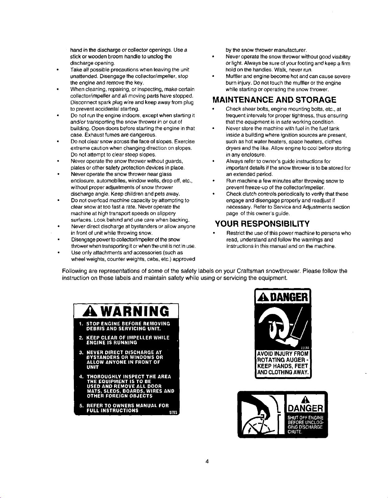
Following are representations of some of the safety labelson your Craftsman snowtbrower. Please follow the
instruction on these labels and maintain safety while using or servicing the equipment.
DAHGER
WARNING ]
4

Lay the hardware pieces from the hardware pack on the figure here and you will have automatically sorted these
according to the steps of the assembly procedure described later. (Only one unit of each hardware has been shown per group.
The number in parenthesis indicates the total number of the hardware needed in that group.)
A Lock Wa,_her (4)
Hex B_ (6) (_ j Flutng(6_
Hex Bolt (2)
5/16-16 x 1.75
m
L
__ 5/16-18 x .75
__ 5/16-18 x .75 _ ,
B Cupped Washer (4)
/____ 5116-18 Hex Nut (4)
Cupped Washer (4)
5/16-16 x 1.50 ¢ irrlage Bolt (4)
5/16-18 x 1.50 Carriage Bolt (4)
.a,rp_/
c,p(1) _
Chute Flange Keeper (3) --I
'_-It
I_ Hex Bolt (2) _ --_1
Bellevile Washer ( ) _ _[
1/4-20 _1
:._ Chute _l
:_ _._ j Flange -_
_L "" %. ,,/ Bracket -_1
InOtcth°lWn _1
size) ''_1
G Hairpin Clip (1) Flat ---II
\ _ Washer(2)At
D _. Hairpin Clip (21 _
12 ©
Wat'a_WaehS/__2) C) Fe(rlr) e
Replacement Part
,,a,em,
'_ Shear Bolt (2) 5/16-18x 1,5
0,,F, i
_// Flat Weld Nut (2)
Handle Panel
Rear
• Left
• _L,J
"_i"wo-Piece
Chute Crank _,? ._
Discharge Chute
/
/
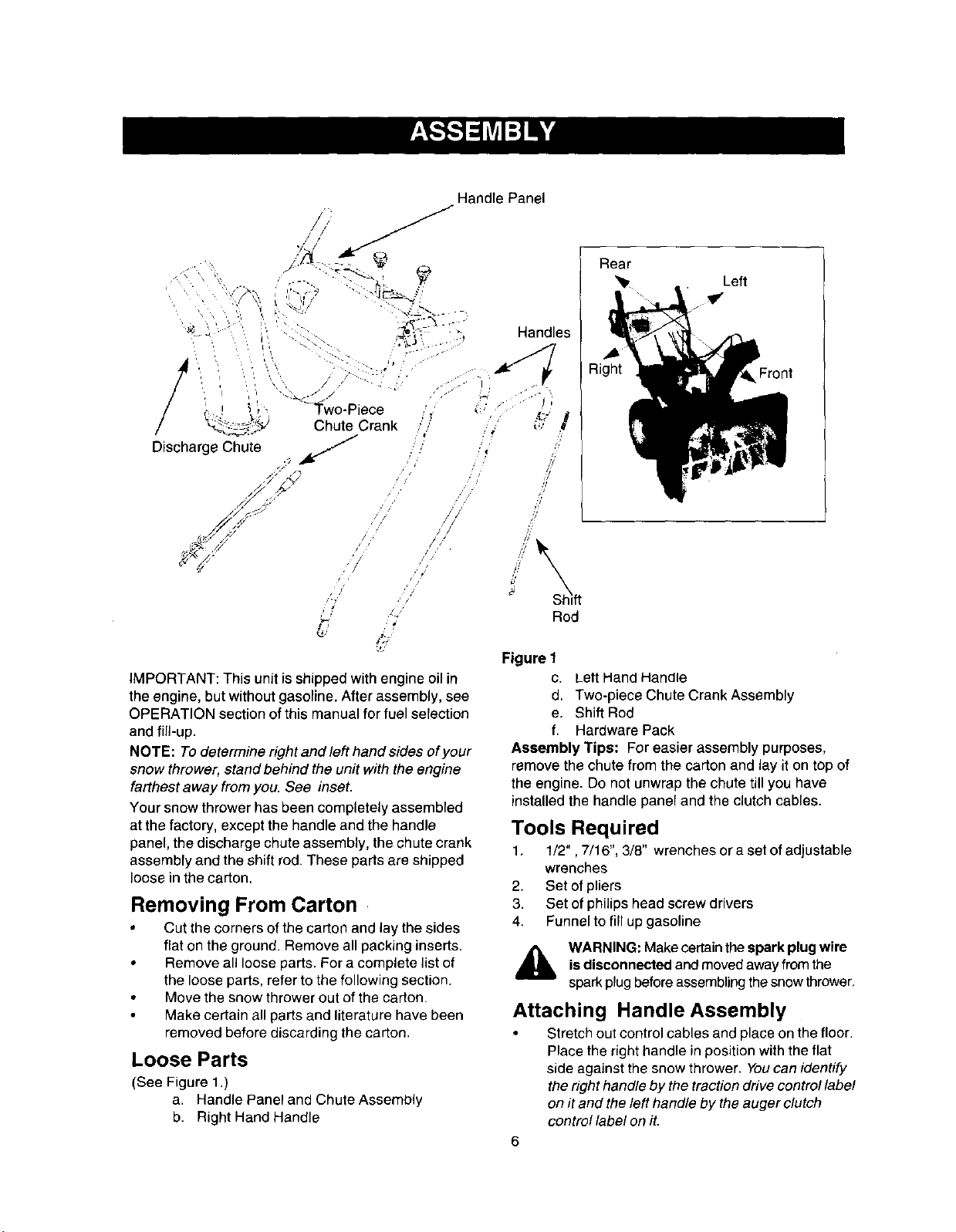
IMPORTANT: This unit is shipped with engine oil in
the engine, but without gasoline. After assembly, see
OPERATION section of this manual for fuel selection
and fill-up.
NOTE: To determine right and left hand sides of your
snow thrower, stand behind the unit with the engine
farthest away from you. See inset•
Your snow thrower has been completely assembled
at the factory, except the handle and the handle
panel, the discharge chute assembly, the chute crank
assembly and the shift rod• These parts are shipped
loose in the carton.
Removing From Carton
• Cut the corners of the carton and lay the sides
flat on the ground• Remove all packing inserts.
• Remove all loose parts. For a complete list of
the loose parts, refer to the following section•
• Move the snow thrower out of the carton.
Make certain all parts and literature have been
removed before discarding the carton.
Loose Parts
(See Figure 1.)
a. Handle Panel and Chute Assembly
b. Right Hand Handle
Handles
R i Front
4"
,i/
W
//
Rod
Figure 1
c. Lett HandHandle
d, Two-piece Chute Crank Assembly
e. Shift Rod
f. Hardware Pack
Assembly Tips: Foreasier assembly purposes,
remove the chute from the cartonand layit on topof
the engine. Do not unwrapthe chute tillyou have
installedthe handle panel and the clutch cables.
Tools Required
1, 1/2", 7/16", 3/8" wrenches or a set ofadjustable
wrenches
2, Set ofpliers
3. Set of philipshead screw drivers
4. Funnelto fill up gasoline
i_ WARNING:Make certain the spark plug wire
isdisconnectedand movedaway from the
sparkplugbefore assemblingthesnowthrower.
Attaching Handle Assembly
• Stretch out control cables and place on the floor•
Place the right handle in position with the flat
side against the snow thrower• Youcan identify
the right handle bythe traction drive control label
on it and the left handle by the auger clutch
control label on it.

Secure bottom hole in the handle to the snow
thrower using 5/16 x0.75" hex bolt and lock
washer from the hardware pack (group A on
page 5 ).Do nottighten at this time. See Figure 2.
Lock Washer &
Hex Bolt (1-3/4")
Right Handle
Handle _[Washer &
Tab Hex Bolt (3/4")
Figure 2
Place a handle tab, included inthe hardware
pack (group Aonpage 5),over the upper hole in
handle so that the contour of the handle tab
matches that of the handle. See Figure 2.
Secure handle tab to the snow thrower using
hex bolt (5/16 x 1.75" long) and lock washer
from the same group inthe hardware pack. Do
not tighten at this time.
Attach the left handle in the same manner. Do
not tighten at this time.
Place the handle panel in position between the
handles so the ends of the curved part of the
handles go through the slots in the handle panel.
While placing the handle panel, make sure to
route chute and chute cable between the
handles underneath the panel keeping the cable
on top of the engine. Align the holes in the
handle with theholes on two sides of the handle
panel. See Figure 3.
Right Handle
Hex Bolt
and Flange
Nut
Handle Panel
\
CarriageBolt,
andHexNut
Figure 3
nHoles
Attach the handle panelto the handle with two
carriage bolts, cupped washers (cupped side
against the handle panel) and hex nuts on each
side. See Figure 3. You will find these fasteners
in the hardware pack (group Bon page 5). Align
the contour of the carriage bolt head with the
handle.
Attaching Chute
Place the chute assemblyoverthe chute
opening withthe chute facingfrontof the unit.
NOTE: Make sure that the chute cables are
straightened while assembling the chute.
• Place the chute flange keeper (flat side down)
beneath lip of chute assembly as shown in
Figure 4.You will find the chute flange keepers in
group E of the hardware pack.
• Insert 1/4-20 hex bolt and flange nutfrom group
E up through chute flange keeper and chute
assembly as shown in Figure 4. Do nottighten at
this time. Rotate chute to install all the flange
keepers.
Chute
Hex
Nut
\
Chute
'_e Flange
x Keeper
Bolt
Figure 4
After assembling all three chute flange keepers,
tighten, then back off 1/4 turn to allow easier
movement of the chute. Use (2) 7/16" wrenches.
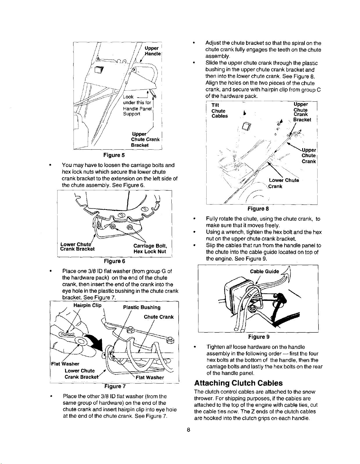
Attaching Chute Crank
On the leftside of the handle panel, place the
upperchute crankbracket on tothe insideofthe
handle panelsupport. See Figure5. You willfind
thisbracket and associated hardware in group F
of hardware pack
• Insert hex bolt through the upper chute crank
bracket, handle panel support, and upper left
handle. Secure the bracket using cupped
washer and hex nut. Make sure that the cupped
side ofthe washer is set against the handle.
ook
Supped
Chute Crank ;
Bracket
Figure 5
You may have to loosenthe carriage boltsand
hex lock nutswhichsecure the lower chute
crank bracket to the extension on the left side of
the chute assembly. See Figure 6.
Adjust the chute bracket so that the spiral on the
chute crank fully engages the teeth on the chute
assembly.
Slide the upper chute crank through the plastic
bushing in the upper chute crank bracket and
then into the lower chute crank. See Figure 8.
Align the holes on the two pieces of the chute
crank, and secure with hairpin clip from group C
of the hardware pack.
Tilt Upper
Chute _, Crank
Cables
Chute
j_ _ Bracket
_ \\ ::,
.Upperl
Chute
Crank
\
LowerChute
"_\_Crank
Figure 8
Crank Bracket Hex L_cEkNut'
Figure 6
Placeone 3/8 ID flat washer(fromgroupG of
the hardwarepack) on the end of thechute
crank,then insert the end of the crank intothe
eye hole inthe plasticbushing inthe chute crank
bracket. See Figure 7.
HairpinClip PlasticBushing
Chute Crank
LowerChute J
CrankBracket_ "FlatWasher
=
Figure 7
Placethe other3/8 ID flat washer (fromthe
same group of hardware) onthe end ofthe
chutecrank and insert hairpinclipintoeye hole
at the end ofthe chutecrank. See Figure7.
• Fullyrotate the chute, using the chute crank, to
make sure that it moves freely.
Using a wrench, tighten the hex bolt and the hex
nut on the upper chute crank bracket.
• Slip the cables that run from the handle panel to
the chute into the cable guide located on top of
the engine. See Figure 9.
CableGuide_/_
Figure 9
Tightenall loose hardware on the handle
assembly inthe following order-- first the four
hex bolts at the bottom of the handle, then the
carriage bolts and lastly the hex bolts on the rear
of the handle panel.
Attaching Clutch Cables
The clutchcontrol cablesare attached tothe snow
thrower.For shippingpurposes, ifthecables are
attachedto the top of theengine withcable ties, cut
thecable ties now.The Z ends ofthe clutchcables
are hooked into the clutch grips on each handle.
8
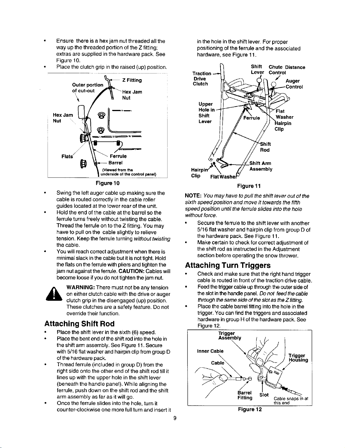
Ensurethereisahexjamnutthreadedallthe
way up the threaded portion of the Z fitting;
extras are supplied inthe hardware pack. See
Figure 10.
Place the clutch grip inthe raised (up) position.
Outer
of cut-out
\
Hex Jam
Nut "_ '
Z Fitting
Nut
in the hole in the shift lever. For proper
positioning of the ferrule and the associated
hardware, see Figure 11.
Shift Chute Distance
Lever Control
Drive Auger
Clutch
Upper
Shift Washer
Lever
Flat
Clip
Rod
_(Vi_ii_i_theont rol panel)
Figure 10
Swing the left auger cable up making sure the
cable is routed correctly in the cable roller
guides located at the lower rear of the unit.
Hold the end of the cable at the barrel so the
ferrule turns freely without twisting the cable.
Thread the ferrule on to the Z fitting. You may
have to pull on the cable slightly to relieve
tension. Keepthe ferrule turning without twisting
the cable.
You will reach correct adjustment when there is
minimal slack in the cable but it is nottight. Hold
the flats on the ferrule with pliers and tighten the
jam nut against the ferrule. CAUTION: Cables will
become loose ifyou do not tighten the jam nut.
WARNING: There must not be any tension
A
on either clutch cable with the drive or auger
clutch grip in the disengaged (up) position.
These clutches are a safety feature. Do not
override their function.
Attaching Shift Rod
Placethe shiftlever inthe sixth(6) speed.
Placethe bent end of the shift rod into thehole in
the shift arm assembly. See Figure 11. Secure
with 5/16flat washer and hairpin clip from group D
of the hardware pack.
Thread ferrule (included in group D) from the
right side onto the other end of the shift rod till it
lines up with the upper hole in the shift lever
(beneath the handle panel). While aligning the
ferrule, push down on the shift rod and the shift
arm assembly as far as it will go.
• Once the ferrule slides into the hole, turn it
counter-clockwise one more full turn and insert it
Hair Assembly
Clip
Figure 11
NOTE: You may have topull theshift lever out of the
sixth speed position and move it towards the fifth
speed position until the ferrule slides into the hole
without force.
Secure theferrule to the shift lever with another
5/16 flat washer and hairpin clip from group D of
the hardware pack. See Figure 11.
Make certain tocheck for correct adjustment of
the shift rod as instructed inthe Adjustment
section before operating the snow thrower.
Attaching Turn Triggers
Check and make sure that the right hand trigger
cable is routed in front of the traction drive cable.
• Feedthe triggercableup through the outer sideof
theslot inthe handle panel. Donot feedthe cable
throughthesame side of the slotas theZ fitting.
• Placethe cable barrel fitting into the hole inthe
trigger. You can find the triggers and associated
hardware in group Hof the hardware pack. See
Figure 12.
Trigger
Assembly /
Inner Cable _'N_
Slot
Cable snaps in at
this end
Figure 12
9
Trigger
Housing
/
Pull on the cable and rotate itaround the bottom
of the trigger, with the inner cable inthe slot, until
the cable end can be pushed intothe trigger
housing and snapped tight. See Figure 12.
Note: When the cable is installed correctly, you
should not beable topull the cable out of the trigger
housing.
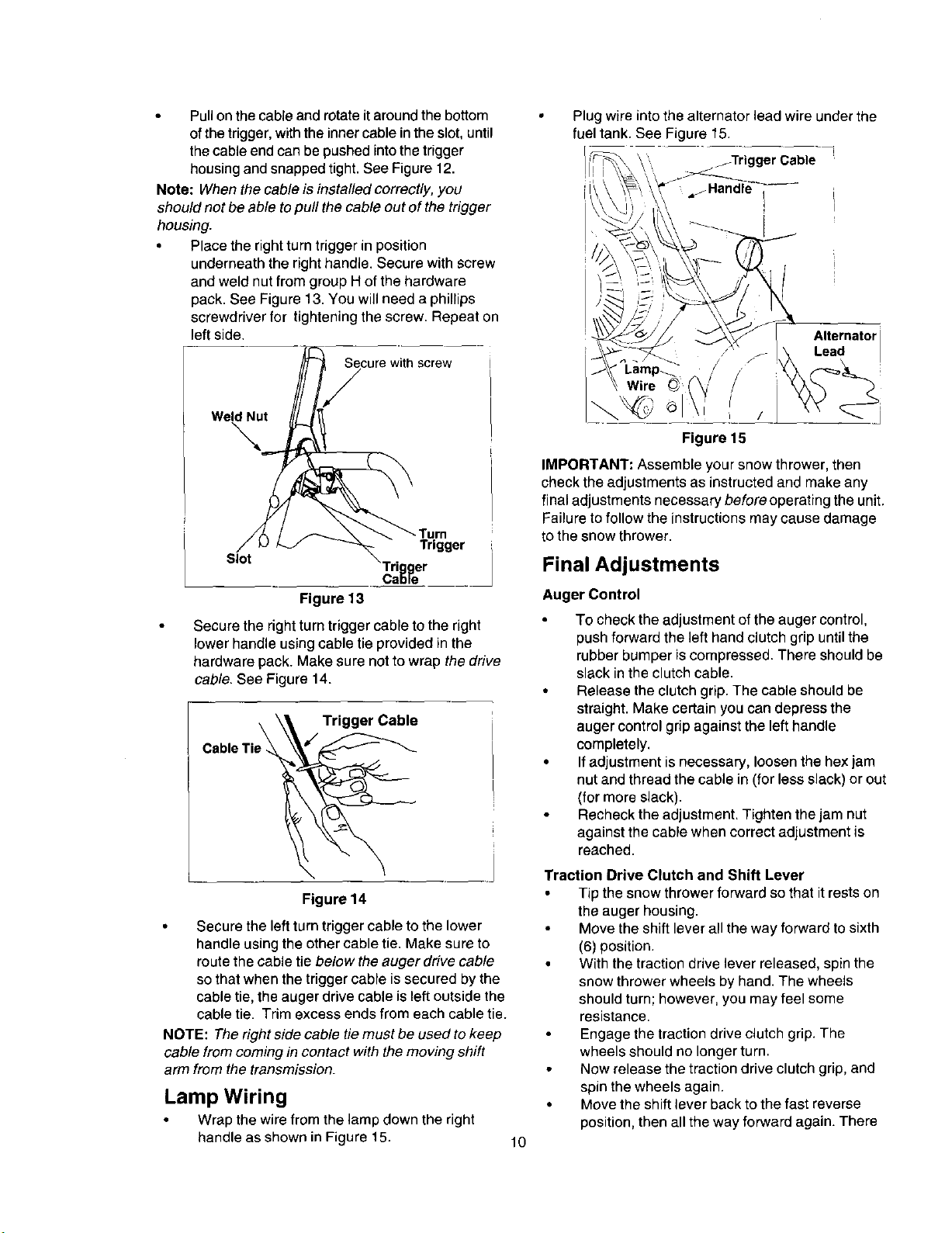
• Place the right turn trigger in position
underneath the right handle. Secure with screw
and weld nut from group H of the hardware
pack. See Figure 13. You will need a phillips
screwdriver for tightening the screw. Repeat on
left side.
Secure with screw
WeldNut
Slot
i rl er
Ca_le
Trigger
Figure 13
Secure the right turn trigger cable to the right
lower handle using cable tie provided in the
hardware pack. Make sure not to wrap the drive
cable. See Figure 14.
CableTie_ Trigger Cable
Figure 14
Secure the left turn trigger cable to the lower
handle using the other cable tie. Make sure to
route the cable tie below the auger drive cable
so that when the trigger cable is secured by the
cable tie, the auger drive cable is left outside the
cable tie. Trim excess ends from each cable tie.
NOTE: The right side cable tie must be used to keep
cable from coming in contact with the moving shift
arm from the transmission.
Lamp Wiring
• Wrap the wire from the lamp down the right
handle as shown in Figure 15.
• Plugwireinto the alternator lead wire under the
fuel tank. See Figure 15.
jTrigger Cable
" ,,_Handle" I
Alternatori
Lead
Figure 15
IMPORTANT: Assemble your snow thrower, then
check the adjustments as instructed and make any
final adjustments necessary before operating the unit.
Failure to follow the instructions may cause damage
to the snow thrower.
Final Adjustments
Auger Control
To check the adjustment of the auger control,
push forward the left hand clutch grip until the
rubber bumper is compressed. There should be
slack inthe clutch cable.
Release the clutch grip. The cable should be
straight. Make certain you can depress the
auger control gnp against the left handle
completely.
If adjustment is necessary, loosen the hex jam
nut and thread the cable in (for less slack) or out
(for more slack).
Recheck the adjustment. Tighten the jam nut
against the cable when correct adjustment is
reached.
Traction Drive Clutch and Shift Lever
Tip the snow throwerforward so that it rests on
the auger housing.
Move the shift leverall the way forward to sixth
(6) position.
• Withthe tractiondrive lever released, spin the
snow throwerwheels by hand.The wheels
should turn;however, you may feel some
resistance.
Engagethe tractiondrive clutchgrip. The
wheelsshould nolongerturn.
Now release the tractiondrive clutch grip,and
spin the wheels again.
• Move the shift lever back to thefast reverse
position,thenall the way forward again. There
10
should beno resistance inthe shift lever, and the
wheels should turn.
Ifyou face resistance when moving the shift
lever or the snow thrower wheels stop when they
should not, loosen the lock nut on the traction
drive cable and unthread the cable one turn.
If the wheels can still be turned when you
engage the traction drive clutch grip, loosen the
lock nut on the traction drive cable and thread
the cable in one turn.
Recheck the adjustment and repeat adjustment
as necessary. Tighten the lock nut to secure the
cable when correct adjustment is reached.
NOTE: If you are not sure that you have reached
correct adjustment, referto theAdjustment section on
page 20.
Skid Shoe
The space between the shave plate and the ground
can be adjusted. For close snow removal, place skid
shoes in the low position. Use middle or high
position when area to be cleared is uneven.
NOTE: It is not recommended that you operate this
snow thrower ongravel as loose gravel can be easily
picked up and thrown by the auger causing an injury
or damage to the snow thrower.
If for some reason, you have to operate the
snow thrower on gravel, keep the skid shoe in
the highest position for maximum clearance
between the ground and the shave plate.
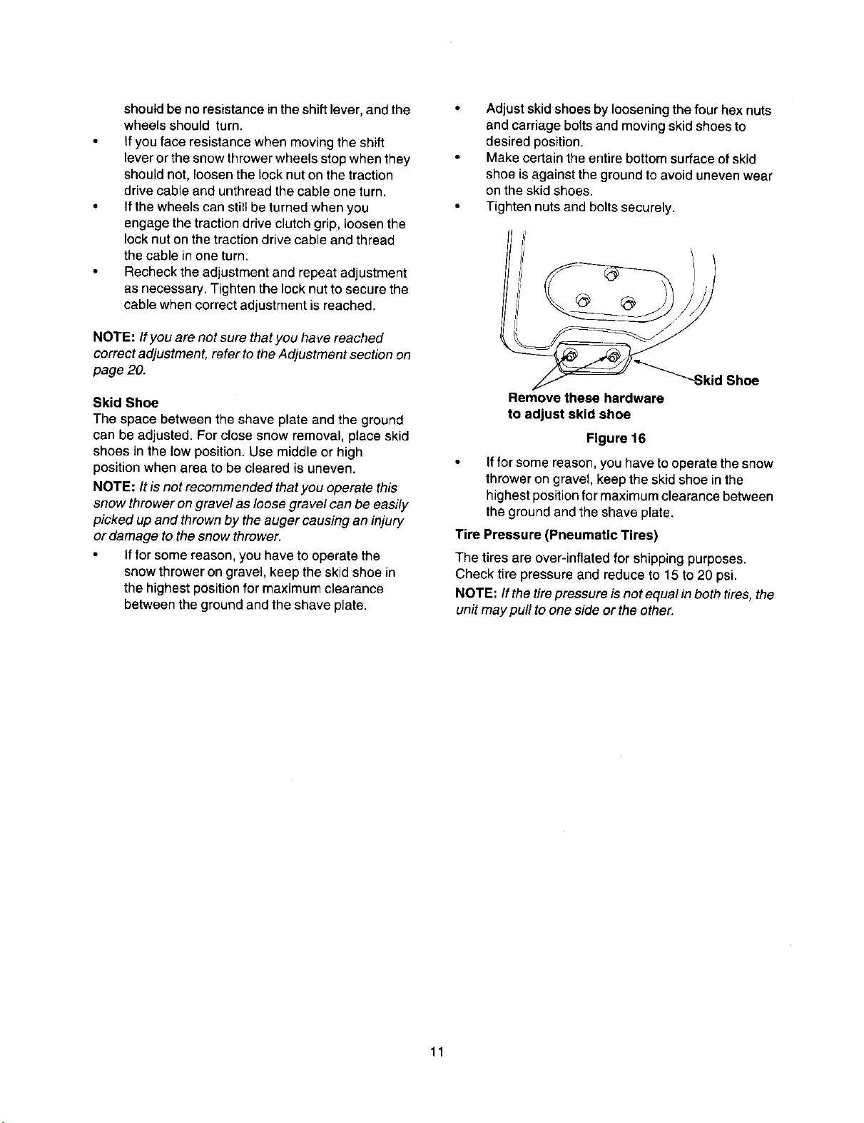
Adjustskid shoes by loosening the four hex nuts
and carriage bolts and moving skid shoes to
desired position.
Make certain the entire bottom surface of skid
shoe is against the ground to avoid uneven wear
on the skid shoes.
Tighten nuts and bolts securely.
--Skid Shoe
Remove these hardware
to adjust skid shoe
Figure 16
If for some reason, you have to operate the snow
thrower on gravel, keep the skid shoe inthe
highest position for maximum clearance between
the ground and the shave plate.
Tire Pressure (Pneumatic Tires)
The tires are over-inflated for shipping purposes.
Check tire pressure and reduce to 15 to 20 psi.
NOTE: Ifthe tire pressure is not equal inboth tires, the
unit may pull to one side or the other.
11
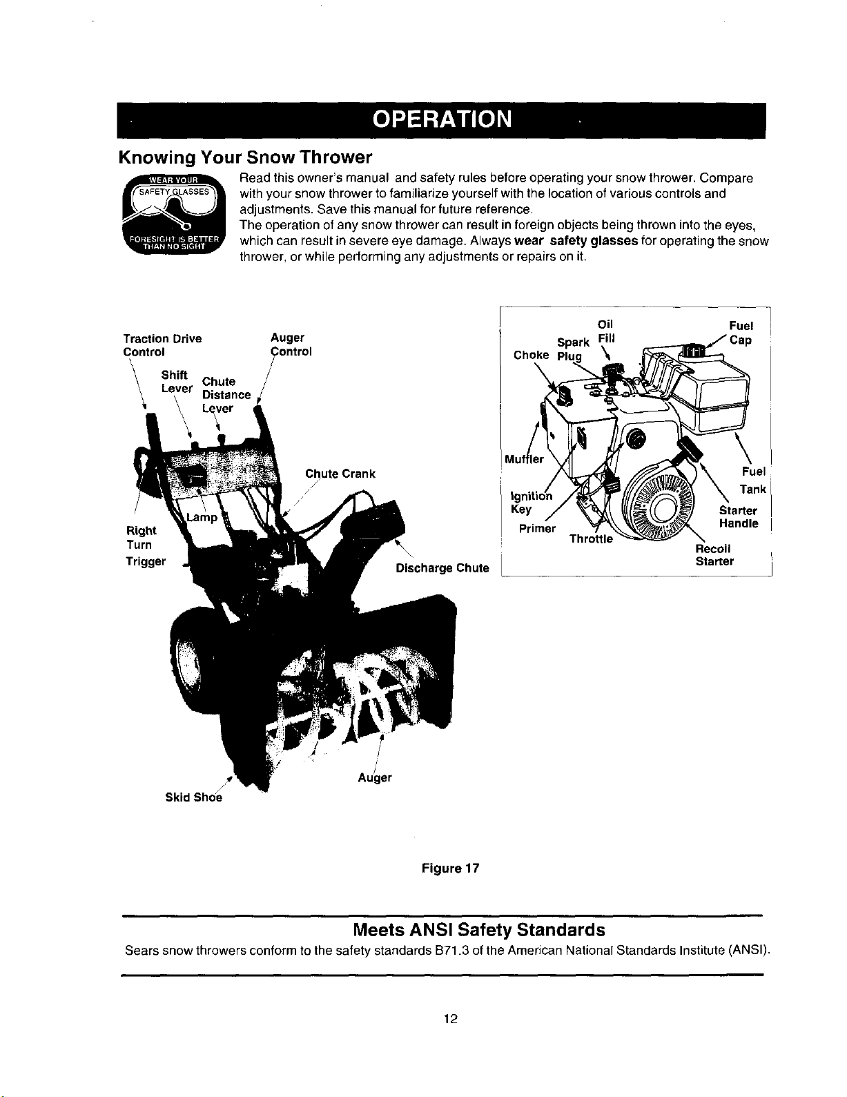
Knowing Your Snow Thrower
Read this owner's manual and safety rules before operating your snow thrower. Compare
with your snow thrower to familiarize yourself with the location of various controls and
adjustments. Save this manual for future reference.
The operation of any snow thrower can result in foreign objects being thrown into the eyes,
which can result in severe eye damage. Always wear safety glasses for operating the snow
thrower, or while performing any adjustments or repairs on it.
Traction Drive Auger
Control_ Control
Shift
Chute
Lever
Distance
Lever
Right
Turn
Trigger
ChuteCrank
/
/
/
\,
DischargeChute
Choke
Key
Primer
Oil
Spark Fill
\
Throttle
Starter
Handle
Recoil
Starter
Fuel
Tankl
Fuel
i
/
/
Au_]er
Skid Shoe
Figure 17
Meets ANSI Safety Standards
Sears snow throwers conform to the safety standards B71.3 of the American National Standards Institute (ANSI).
12
 Loading...