

Craftsman 247888480 Owner’s Manual

Operator's Manual
P R 0 F E S S I 0 N A L
45" SNOW THROWER
Model No. 247.88848
, SAFETY
, ASSEMBLY
, OPERATION
, MAINTENANCE
CAUTION: Before using
this product, read this
, PARTS LIST
o ESPANOL
manual and follow all
safety rules and operating
instructions.
Sears Brands Management Corporation, Hoffman Estates, IL 60179, U.S.A.
Visit our website: www.craftsman.com FORMNO.769-06014C
7/18/2011

WarrantyStatement..................................Page2
SafeOperation Practices .......................... Page 3
Safety Labels ............................................ Page 7
Assembly .................................................. Page 8
Operation .................................................. Page 14
Service and Maintenance ......................... Page 19
Off-Season Storage .................................. Page 27
Troubleshooting ........................................ Page 28
Parts List ................................................... Page 29
Repair Protection Agreement ................... Page 49
Espa_ol ..................................................... Page 50
Service Numbers ...................................... Back Cover
CRAFTSMAN PROFESSIONAL TWO YEAR FULL WARRANTY
FORTWOYEARSfromthe dateof purchase,this productiswarrantedagainstanydefectsin materialor workmanship.A defectiveproductwill
receivefreerepairorreplacementif repairisunavailable.
Thiswarrantyappliesfor onlyoneyearfromthedateof purchaseifthis productiseverusedwhileprovidingcommercialservicesor if rentedto
anotherperson.
Forwarrantycoveragedetailsto obtainfreerepairor replacement,visitthewebsite:www.craftsman.com
Thiswarranty coversONLYdefects inmaterial andworkmanship. Warrantycoverage does NOTinclude:
• Expendableitemsthatcanwearoutfromnormalusewithinthewarrantyperiod,includingbut notlimitedto augers,augerpaddles,drift
cutters,skidshoes,shaveplate,shearpins,sparkplug,aircleaner,belts,andoil filter.
• Standardmaintenanceservicing,oilchanges,or tune-ups.
• Tire replacementor repaircausedby puncturesfromoutsideobjects,suchasnails,thorns,stumps,orglass.
• Tireor wheelreplacementor repairresultingfromnormalwear,accident,orimproperoperationormaintenance.
• Repairsnecessarybecauseof operatorabuse,includingbutnot limitedtodamagecausedbyover-speedingthe engine,orfromimpacting
objectsthatbendthe frame,augershaft,etc.
• Repairsnecessarybecauseof operatornegligence,includingbutnotlimitedto,electricalandmechanicaldamagecausedby improper
storage,failureto usethepropergradeandamountofengineoil,or failureto maintaintheequipmentaccordingtotheinstructionscontained
intheoperator'smanual.
• Engine(fuelsystem)cleaningorrepairscausedbyfueldeterminedto becontaminatedoroxidized(stale).Ingeneral,fuelshouldbeused
within30 daysof itspurchasedate.
• Normaldeteriorationandwearoftheexteriorfinishes,or productlabelreplacement.
Thiswarrantygivesyouspecificlegalrights,andyou mayalsohaveotherrightswhichvaryfromstatetostate.
Sears Brands Management Corporation, Hoffman Estates, IL 60179
EngineOilType: 5W-30
EngineOilCapacity: 37ounces
FuelCapacity: Approx.5Quarts
SparkPlug: F6RTC(951-10292)
SparkPlugGap: .020"to.030"
©KCDIR LLC
ModelNumber.................................................................
Serial Number .................................................................
Dateof Purchase.............................................................
Recordthemodelnumber,serialnumber
anddateof purchaseabove
2

Thissymbolpointsout importantsafetyinstructionswhich,if not
followed,couldendangerthepersonalsafetyand/orpropertyof
yourselfandothers. Readandfollowall instructionsin thismanual
beforeattemptingtooperatethismachine.Failuretocomplywith
theseinstructionsmayresultin personalinjury.Whenyouseethis
symbol,HEEDITSWARNING!
Thismachinewasbuiltto beoperatedaccordingtothesafeopera-
tionpracticesinthis manual.Aswithanytypeof powerequipment,
carelessnessorerroron thepartofthe operatorcanresultin serious
injury.Thismachineiscapableofamputatingfingers,hands,toes
andfeetandthrowingdebris.Failuretoobservethefollowingsafety
instructionscouldresultin seriousinjuryor death.
CALIFORNIA PROPOSITION 65
EngineExhaust,someof itsconstituents,andcertainvehicle
componentscontainoremitchemicalsknownto StateofCalifornia
tocausecancerandbirthdefectsorotherreproductiveharm,
TRAiNiNG
• Read,understand,andfollowallinstructionson themachineand
in themanual(s)beforeattemptingto assembleandoperate.
Failuretodo socan resultinseriousinjurytotheoperatorand/
orbystanders.Keepthismanualin a safeplaceforfutureand
regularreferenceandfor orderingreplacementparts.
• Befamiliarwithall controlsandtheirproperoperation.Knowhow
tostopthe machineanddisengagethemquickly.
• Neverallowchildrenunder14yearsof agetooperatethis
machine.Children14andover shouldreadandunderstandthe
instructionsandsafeoperationpracticesin thismanualandon
themachineandbe trainedandsupervisedbyanadult.
Neverallowadultsto operatethismachinewithoutproper
instruction.
• Thrownobjectscancauseseriouspersonalinjury.Planyour
snow-throwingpatterntoavoiddischargeof materialtoward
roads,bystandersandthe like.
Keepbystanders,petsandchildrenat least75feetfromthe
machinewhileitisin operation.Stopmachineifanyoneenters
thearea.
• Exercisecautiontoavoidslippingorfalling,especiallywhen
operatinginreverse.
Your Responsibility--Restrict the useof thispowermachineto
personswhoread,understandandfollowthewarningsand instruc-
tionsin thismanualandon the machine.
SAVE THESE INSTRUCTIONS!
PREPARATION
Thoroughlyinspecttheareawheretheequipmentisto beused.
Removeall doormats,newspapers,sleds,boards,wiresandother
foreignobjects,whichcouldbe trippedoverorthrownbythe auger/
impeller.
• Alwayswearsafetyglassesor eyeshieldsduringoperationand
whileperformingan adjustmentor repairto protectyoureyes.
Thrownobjectswhichricochetcancauseseriousinjurytothe
eyes.
Donot operatewithoutwearingadequatewinteroutergarments.
Donot wearjewelry,longscarvesorotherlooseclothing,which
couldbecomeentangledin movingparts.Wearfootwearwhich
willimprovefootingonslipperysurfaces.
Usea groundedthree-wireextensioncordand receptacleforall
machineswithelectricstartengines.
Disengageallcontrolleversbeforestartingtheengine.
Adjustcollectorhousingheighttocleargravelorcrushedrock
surfaces.
• Neverattempttomakeanyadjustmentswhileengineis running,
exceptwherespecificallyrecommendedintheoperator'smanual.
Letengineandmachineadjustto outdoortemperaturebefore
startingtoclearsnow.
3
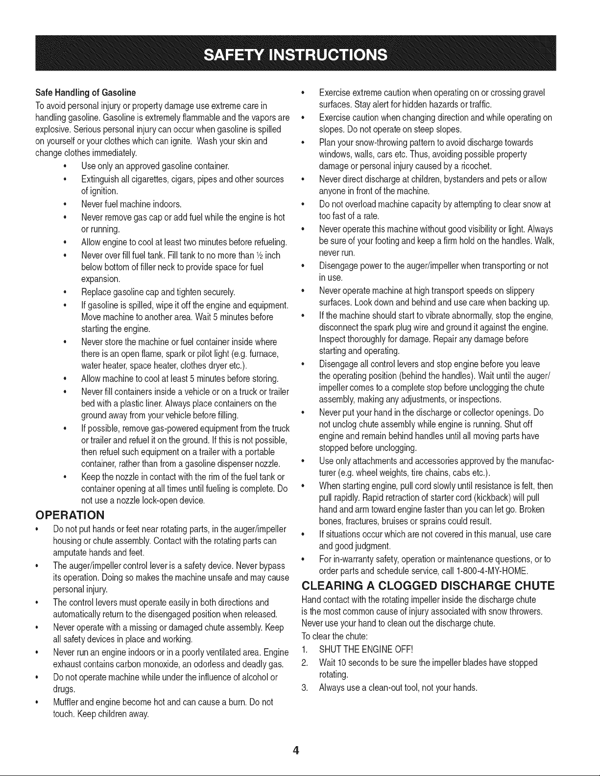
SafeHandling of Gasoline
Toavoidpersonalinjuryor propertydamageuseextremecarein
handlinggasoline.Gasolineisextremelyflammableandthevaporsare
explosive.Seriouspersonalinjurycanoccurwhengasolineis spilled
onyourselforyourclotheswhichcan ignite.Washyourskinand
changeclothesimmediately.
• Useonlyanapprovedgasolinecontainer.
• Extinguishall cigarettes,cigars,pipesandothersources
ofignition.
• Neverfuelmachineindoors.
• Neverremovegascaporaddfuelwhiletheengineishot
or running.
• Allowengineto coolat leasttwo minutesbeforerefueling.
• Neveroverfill fueltank. Filltankto no morethan1/2inch
belowbottomoffiller neckto providespaceforfuel
expansion.
• Replacegasolinecapandtightensecurely.
• Ifgasolineis spilled,wipeit offtheengineandequipment.
Movemachinetoanotherarea.Wait5 minutesbefore
startingtheengine.
• Neverstorethemachineorfuel containerinsidewhere
thereis anopenflame,sparkor pilotlight(e.g.furnace,
waterheater,spaceheater,clothesdryeretc.).
• Allowmachinetocoolat least5 minutesbeforestoring.
• Neverfillcontainersinsidea vehicleor ona truckortrailer
bedwitha plasticliner.Alwaysplacecontainersonthe
groundawayfromyourvehiclebeforefilling.
• If possible,removegas-poweredequipmentfromthetruck
ortrailerand refueliton the ground.Ifthisis notpossible,
thenrefuelsuchequipmentona trailerwitha portable
container,ratherthanfromagasolinedispensernozzle.
• Keepthenozzleincontactwiththe rimofthefueltankor
containeropeningatalltimesuntilfuelingiscomplete.Do
notuse a nozzlelock-opendevice.
OPERATION
• Do notputhandsorfeetnear rotatingparts,in theauger/impeller
housingorchuteassembly.Contactwiththe rotatingpartscan
amputatehandsandfeet.
• Theauger/impellercontrolleverisasafetydevice.Neverbypass
itsoperation.Doingsomakesthe machineunsafeandmaycause
personalinjury.
• Thecontrolleversmustoperateeasilyin bothdirectionsand
automaticallyreturntothedisengagedpositionwhenreleased.
• Neveroperatewitha missingordamagedchuteassembly.Keep
all safetydevicesinplaceandworking.
• Neverrunanengineindoorsor ina poorlyventilatedarea.Engine
exhaustcontainscarbonmonoxide,anodorlessanddeadlygas.
• Do notoperatemachinewhileundertheinfluenceof alcoholor
drugs.
• Mufflerandenginebecomehotandcan causea burn.Do not
touch.Keepchildrenaway.
• Exerciseextremecautionwhenoperatingonorcrossinggravel
surfaces.Stayalertforhiddenhazardsortraffic.
• Exercisecautionwhenchangingdirectionandwhileoperatingon
slopes.Do notoperateon steepslopes.
• Planyoursnow-throwingpatternto avoiddischargetowards
windows,walls,carsetc.Thus,avoidingpossibleproperty
damageorpersonalinjurycausedby a ricochet.
• Neverdirectdischargeat children,bystandersandpetsorallow
anyoneinfrontof themachine.
• Donot overloadmachinecapacitybyattemptingtoclearsnowat
toofastof a rate.
• Neveroperatethismachinewithoutgoodvisibilityorlight.Always
be sureof yourfootingand keepa firmholdon thehandles.Walk,
neverrun.
• Disengagepowertotheauger/impellerwhentransportingor not
in use.
• Neveroperatemachineathightransportspeedson slippery
surfaces.Lookdownand behindandusecarewhenbackingup.
• Ifthemachineshouldstartto vibrateabnormally,stopthe engine,
disconnectthe sparkplugwireandgroundit againsttheengine.
Inspectthoroughlyfor damage.Repairanydamagebefore
startingandoperating.
• Disengageallcontrolleversandstopenginebeforeyouleave
theoperatingposition(behindthehandles).Waituntiltheauger/
impellercomestoa completestopbeforeuncloggingthechute
assembly,makinganyadjustments,or inspections.
• Neverputyourhandinthedischargeor collectoropenings.Do
notunclogchuteassemblywhileengineis running.Shutoff
engineand remainbehindhandlesuntilall movingpartshave
stoppedbeforeunclogging.
• Useonlyattachmentsandaccessoriesapprovedbythemanufac-
turer(e.g.wheelweights,tire chains,cabsetc.).
• Whenstartingengine,pullcordslowlyuntilresistanceisfelt,then
pull rapidly.Rapidretractionofstartercord(kickback)willpull
handandarmtowardenginefasterthanyoucanletgo.Broken
bones,fractures,bruisesorsprainscouldresult.
• Ifsituationsoccurwhichare notcoveredinthis manual,usecare
andgoodjudgment.
• Forin-warrantysafety,operationor maintenancequestions,or to
orderpartsandscheduleservice,call 1-800-4-MY-HOME.
CLEARING A CLOGGED DISCHARGE CHUTE
Handcontactwiththe rotatingimpellerinsidethedischargechute
is the mostcommoncauseofinjuryassociatedwithsnowthrowers.
Neveruseyourhandtocleanoutthedischargechute.
Toclear thechute:
1. SHUTTHEENGINEOFF!
2. Wait 10secondstobe surethe impellerbladeshavestopped
rotating.
3. Alwaysusea clean-outtool,notyourhands.
4
MAINTENANCE & STORAGE
• Nevertamperwithsafetydevices.Checktheirproperoperation
regularly.Refertothemaintenanceandadjustmentsectionsof
thismanual.
• Beforecleaning,repairing,or inspectingmachinedisengageall
controlleversandstoptheengine.Waituntiltheauger/impeller
cometoa completestop.Disconnectthe sparkplugwireand
groundagainsttheengineto preventunintendedstarting.
Checkboltsand screwsforpropertightnessatfrequentintervals
tokeepthemachineinsafeworkingcondition.Also,visually
inspectmachineforanydamage.
Donotchangetheenginegovernorsettingor over-speedthe
engine.Thegovernorcontrolsthe maximumsafeoperatingspeed
ofthe engine.
Snowthrowershaveplatesandskidshoesaresubjecttowear
anddamage.Foryoursafetyprotection,frequentlycheckall
componentsandreplacewithoriginalequipmentmanufacturer's
(OEM)partsonlyaslistedinthe Partspagesof thisoperator's
manual.Useofpartswhichdonot meettheoriginalequipment
specificationsmayleadto improperperformanceandcompro-
misesafety!
Checkcontrolleversperiodicallytoverifytheyengageanddisen-
gageproperlyandadjust,ifnecessary.Referto theadjustment
sectioninthisoperator'smanualforinstructions.
Maintainorreplacesafetyandinstructionlabels,as necessary.
Observeproperdisposallawsand regulationsforgas,oil,etc. to
protecttheenvironment.
Priorto storing,runmachineafewminutestoclearsnowfrom
machineandpreventfreezeupof auger/impeller.
Neverstorethemachineorfuel containerinsidewherethereisan
openflame,sparkorpilot lightsuchas a waterheater,furnace,
clothesdryeretc.
Alwaysrefertothe operator'smanualforproperinstructionson
off-seasonstorage.
Checkfuelline,tank, cap,andfittingsfrequentlyforcracksor
leaks.Replaceif necessary.
Donotcrankenginewithsparkplugremoved.
AccordingtotheConsumerProductsSafetyCommission(CPSC)
andtheU.S.EnvironmentalProtectionAgency(EPA),thisproduct
hasan AverageUsefulLifeof seven(7)years,or 60 hoursof
operation.At theendof theAverageUsefulLifehavethe machine
inspectedannuallybyan authorizedservicedealerto ensurethat
allmechanicalandsafetysystemsareworkingproperlyand not
wornexcessively.Failuretodo so canresultinaccidents,injuries
ordeath.
DO NOT MODIFY ENGINE
Toavoidseriousinjuryor death,do not modifyengineinany way.
Tamperingwiththegovernorsettingcanleadto a runawayengineand
causeitto operateat unsafespeeds.Nevertamperwithfactorysetting
ofenginegovernor.
NOTICE REGARDING EMiSSiONS
EngineswhicharecertifiedtocomplywithCaliforniaandfederal
EPAemissionregulationsforSORE(SmallOffRoadEquipment)are
certifiedto operateonregularunleadedgasoline,and mayinclude
thefollowingemissioncontrolsystems:EngineModification(EM),
OxidizingCatalyst(OC),SecondaryAirInjection(SAI)and ThreeWay
Catalyst(TWO)if soequipped.
SPARK ARRESTOR
Thismachineisequippedwithaninternalcombustionengineand
shouldnotbe usedonor nearany unimprovedforest-covered,
brush-coveredorgrass-coveredlandunlesstheengine'sexhaust
systemisequippedwitha sparkarrestormeetingapplicablelocalor
statelaws(if any)
Ifa sparkarrestorisused,it shouldbe maintainedin effectiveworking
orderbytheoperator.Inthe StateofCaliforniatheaboveisrequired
bylaw (Section4442ofthe CaliforniaPublicResourcesCode).Other
statesmayhavesimilarlaws. Federallawsapplyonfederallands.
A sparkarrestorforthemufflerisavailablethroughyournearestSears
PartsandRepairServiceCenter.
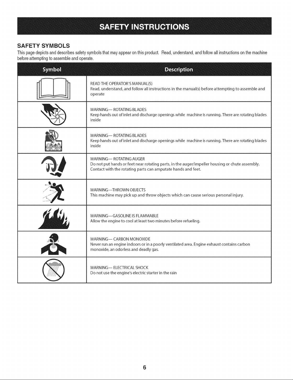
SAFETY SYMBOLS
Thispagedepictsanddescribessafetysymbolsthatmayappearonthisproduct. Read,understand,andfollowall instructionsonthemachine
beforeattemptingtoassembleandoperate.
READ THE OPERATOR'S MANUAL(S)
i
. +
i
Read, understand, and follow all instructions in the manual(s) before attempting to assemble and
operate
WARNING-- ROTATING BLADES
Keep hands out of inlet and discharge openings while machine is running. There are rotating blades
inside
WARNING-- ROTATING BLADES
Keep hands out of inlet and discharge openings while machine is running. There are rotating blades
inside
WARNING-- ROTATING AUGER
Do not put hands or feet near rotating parts, in the auger/impeller housing or chute assembly.
Contact with the rotating parts can amputate hands and feet.
'JIp
WARNING--THROWN OBJECTS
This machine may pick up and throw objects which can cause serious personal injury.
WARNING--GASOLINE IS FLAMMABLE
Allow the engine to cool at least two minutes before refueling.
WARNING-- CARBON MONOXIDE
Never run an engine indoors or in a poorly ventilated area. Engine exhaust contains carbon
monoxide, an odorless and deadly gas+
WARNING-- ELECTRICAL SHOCK
Do not use the engine's electric starter in the rain
6
r
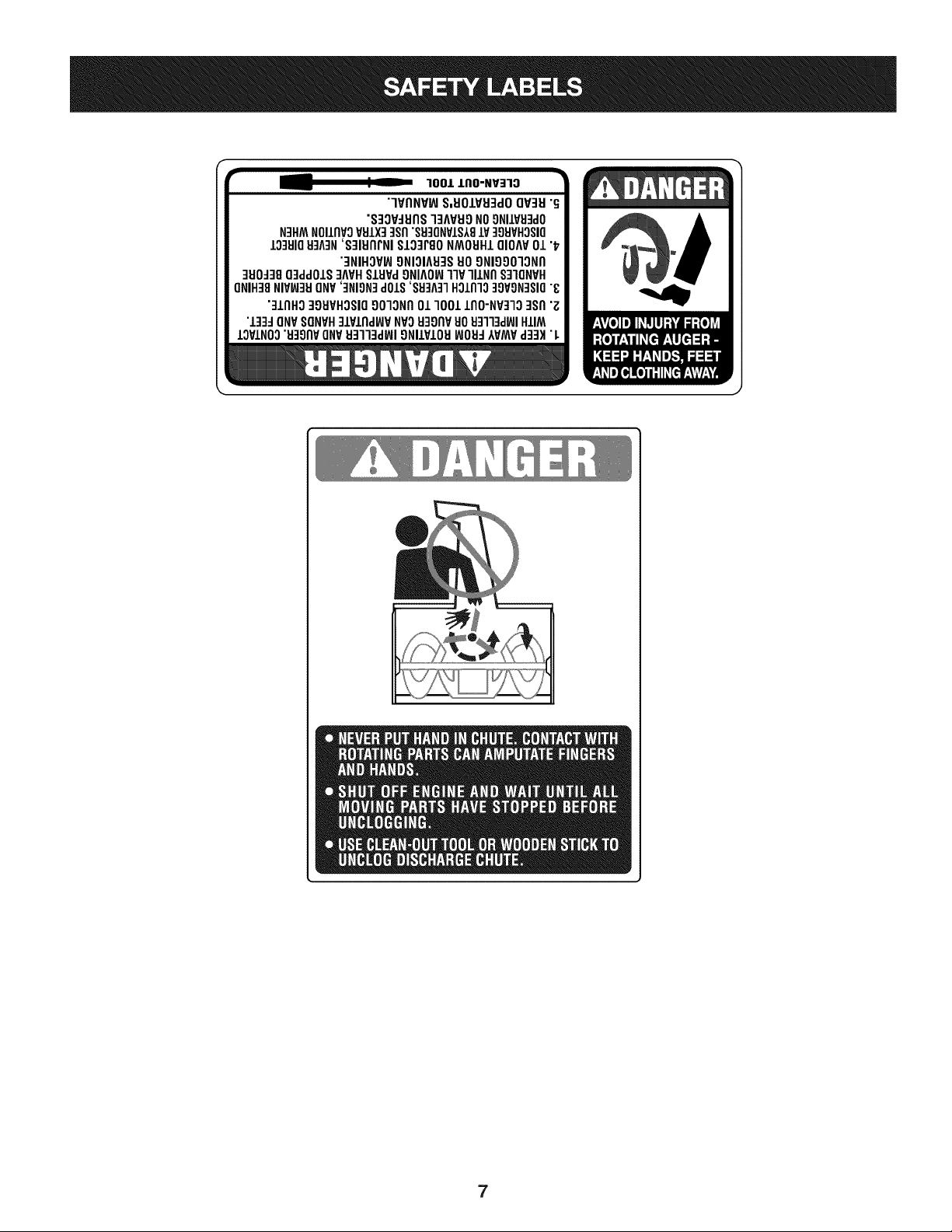
100/.LIIO-NV:IIO
"lVflNV_ S,UOIVU3dOQV3H"G
"S3OV_IJflS]3AVUONO9NIIV_J3dO
N3HMNOIIflVOVSIX]qsfl"S9]ONVIS181V]98VHOSIO
10381083A3N'S]IUflrNI SI03PgoNMOUHIQIOAV01 "_
"3NIHOV_ONIOIA83SUOONIOOO]ONfl
]UO_38O3ddOIS]AVHSlHPd9NIAOW11VlllNfl S]IQNVH
ONIH]8NIVW3UONV']NION]dOlS'88]A]1HOlnlo]9VON]SIO"8
"]lnHg ]gHVHOSIO9010Nfl01 1001lflO-NP]lO ]Sfl "Z
"l]]d ONVSONVH]lPlnd_P NVOH3onvuoHq]l]d_JIHIIM
IOVINO0"u39npONV_J3113dWI9NllVIOU_JOH_IVMVd]3H "L
7

NOTE:Referencesto rightorleft sideofthe snowthrowerare
determinedfromthe operatingpositionlookingforwardtothe frontof
themachine.
REMOVING FROM CRATE
1. Removescrewsfromthebottomofthecratesecuringthesides,
andendsof theshippingcrate.
2. Liftoff thetopoff ofthe crateandsetoutof thewayofthe
assemblyarea.
3. Removeanddiscardplasticbagthatcoversunit.
4. Removeanyloosepartsincludedwithunit(e.g.,Operator's
Manual,etc.).
5. Pushdownonthelowerhandleandpullunitbackout ofcrate.
6. Makecertainthecratehas beencompletelyemptiedbefore
discardingit.
ASSEMBLY
1. Makecertainthe springsatthelowerendofthe augeranddrive
cablesaresecurelyhookedintotheir respectiveactuator
bracketsbeforepivotingthehandleupward.Referto Fig. 10.
a. Placethe speedselectorshiftleverin theF6 position.
b. Cutthecabletiesecuringthetwo piecechutecrankto the
lowerhandle.Thecable tieis usedfor shippingpurposes.
c. Removethe upperwingknobandcarriageboltfromeach
sideof thelowerhandle.Pulluponupperhandleasshown
in Fig.1.Alignupperhandlewiththe lowerhandle.Again,
makecertainthespringsat thelowerendofthe augerand
drivecablesaresecurelyhookedintotheirrespective
actuatorbrackets.Also,removeanyrubberbandssecuring
thecablesto thewing nuts.
Tightenthetwowingknobsalreadyinstalledintheupper
holesto firmlysecurethe upperhandleandsupporttubes.
See Fig.2.
f
!
{
/
/
Figure2
NOTE:Ifthe fullrangeof speeds(forwardand reverse)cannotbe
achieved,refertothe "MakingAdjustments"section.
Chute Directional Control
1. Removethehairpinclipfromthespiralcontrolas showninA
of Fig.3.
2. Insertthechutedirectionalcontrolrodintothefittingonthe spiral
controlas seenin Bof Fig.3.
3. Securewiththe hairpinclippreviouslyremoved.SeeFig.3.
\
Figure1
2.
a.
Securethesupportbracket,upperhandleandlowerhandle
Figure3
withthetwo wingknobsandcarriageboltsremovedearlier.
SeeFig.2.
8
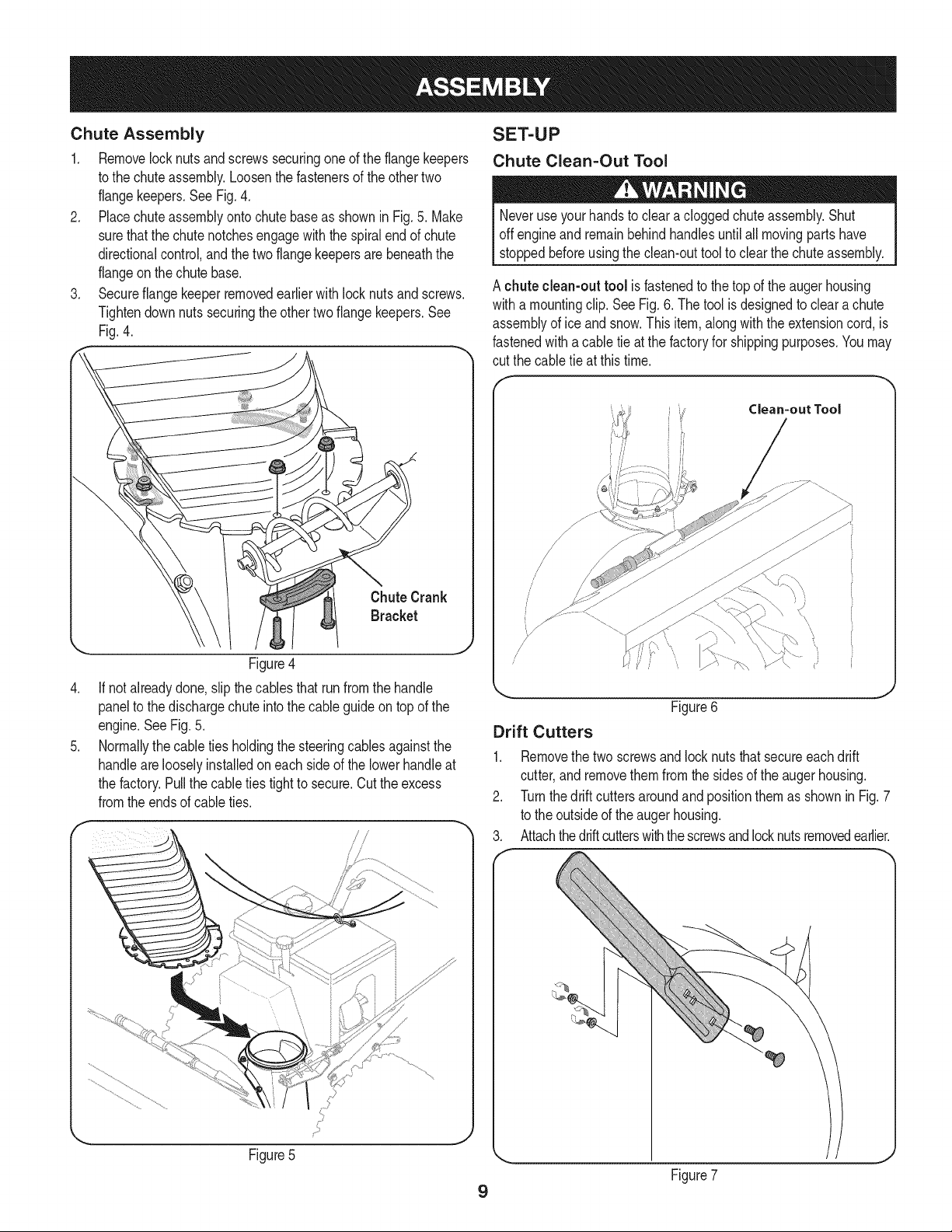
Chute Assembly
1, Removelocknutsandscrewssecuringoneoftheflangekeepers
tothe chuteassembly,Loosenthefastenersoftheothertwo
flangekeepers,SeeFig,4,
2, Placechuteassemblyontochutebaseas showninFig,5,Make
surethatthe chutenotchesengagewiththe spiralendof chute
directionalcontrol,andthetwoflangekeepersarebeneaththe
flangeonthe chutebase,
3, Secureflangekeeperremovedearlierwithlocknutsandscrews,
Tightendownnutssecuringtheothertwoflangekeepers.See
Fig.4.
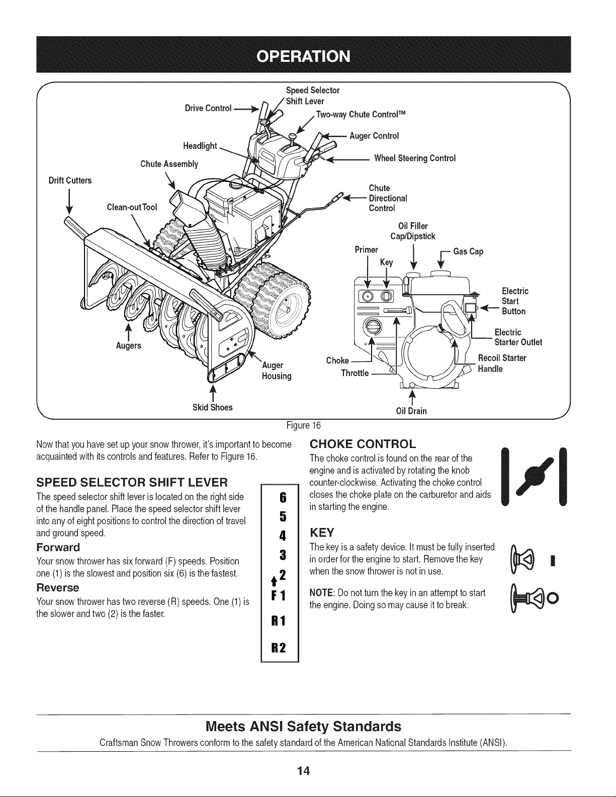
SET-UP
Chute Clean=Out Tool
Neveruseyourhandsto cleara cloggedchuteassembly.Shut
offengineand remainbehindhandlesuntilall movingpartshave
stoppedbeforeusingtheclean-outtooltoclearthechuteassembly,
A chuteclean-outtool isfastenedtothetopof theaugerhousing
witha mountingclip.SeeFig.6.Thetoolisdesignedtocleara chute
assemblyofice andsnow.Thisitem,alongwiththeextensioncord,is
fastenedwitha cabletieat thefactoryfor shippingpurposes.Youmay
cut thecable tieat thistime.
Clean=out Tool
Figure4
.
If notalreadydone,slipthecablesthat runfromthe handle
paneltothe dischargechuteintothecableguideontopof the
engine.SeeFig.5.
.
Normallythecabletiesholdingthe steeringcablesagainstthe
handlearelooselyinstalledoneachsideofthelowerhandleat
thefactory.Pullthecableties tighttosecure.Cuttheexcess
fromtheendsof cableties.
\,
//
//
(,
Figure6
Drift Cutters
1.
Removethetwoscrewsandlocknutsthatsecureeachdrift
cutter,and removethemfromthesidesoftheaugerhousing.
2.
Turnthedrift cuttersaroundandpositionthemasshownin Fig.7
tothe outsideofthe augerhousing.
3.
Attachthedriftcutterswiththescrewsandlocknutsremovedearlier.
J
J
Figure7
9

Shear Pins
A pairof replacementaugershearpinsandbowtiecotterpinshave
beenincludedwithyour snowthrower.Thereareholesprovidedinthe
plasticdashpanelforconvenientstorageof theshearpins.Pushthe
pinsthroughtheholesin thedash panelandsecurewiththebow-tie
cotterpins.See Fig.8.
theareais drybeforestartingtheengine.
• Avoidrepeatedor prolongedcontactwithskinorbreath-
ingofvapor.
Adding Fuel
Useextremecarewhenhandlinggasoline.Gasolineisextremely
flammableandthe vaporsareexplosive.Neverfuelthemachine
indoorsorwhile theengineis hotor running.Extinguishcigarettes,
cigars,pipesandothersourcesofignition.
Alwayskeephandsandfeetclear ofequipmentmovingparts.Donot
usea pressurizedstartingfluid.Vaporsareflammable.
Cleanaroundfuel fillbeforeremovingcaptofuel.
Fuel Level Indicator
TopView
Figure8
Tire Pressure (Pneumatic Tires)
Underanycircumstancedonotexceedmanufacturer'srecom-
mendedpsi.Equaltire pressureshouldbemaintainedatalltimes.
Excessivepressurewhenseatingbeadsmaycausetire/rim
assemblytoburstwithforcesufficienttocauseseriousinjury.Refer
to sidewalloftirefor recommendedpressure.
Thetirescan beover-inflatedfor shippingpurposes.Checkthetire
pressurebeforeoperatingthe snowthrower.Referto thetire sidewall
for rnanufactures'srecommendedpsianddeflate(or inflate)thetires
as necessary.
NOTE:Equaltirepressureisto bemaintainedatalltimesforperfor-
mancepurposes.
Fuel Recommendations
Useautomotivegasoline(unleadedor lowleadedto minimizecombus-
tionchamberdeposits)witha minimumof87 octane.Gasolinewith
upto 10%ethanolor 15%MTBE(MethylTertiaryButylEther)canbe
used.Neverusean oil/gasolinemixtureordirty gasoline.Avoidgetting
dirt, dust,or waterinthe fueltank.DONOTuse E85gasoline.
• Refuelina well-ventilatedareawiththeenginestopped.
Donot smokeorallowflamesor sparksin thearea
wherethe engineis rdueledor wheregasolineis
stored.
• Donot overfillthefueltank.Afterrefueling,makesure
thetankcap isclosedproperlyandsecurely.
• Becarefulnotto spillfuel whenrefueling.Spilledfuel
or fuelvapor mayignite.Ifanyfuelis spilled,makesure
Figure9
2. A fuellevelindicatorislocatedin thefueltank.Filltankuntilfuel
reachesthefuellevelindictor,Figure9.Becarefulnottooverfill.
Checking Oil Level
Theengineis shippedwithoil in theengine.Youmust,however,
checkthe oil levelpriorto operatingthe snowthrower.Runningthe
enginewith insufficientoil cancauseseriousenginedamageand
voidtheenginewarranty.
Someengineswillhavea quarter-turnoilfill/dipstickcap,othersmay
havea threadedoilfill/dipstickcap. Followthe instructionsnextthat
applyto yourenginemodel.
10

Checking Oil Level on Engines with Quarter=Turn
Oil Fill Caps
NOTE:Besuretochecktheengineona levelsurfacewiththeengine
stopped.
Toavoidenginedamage,it isimportantto:
• Checkoillevelbeforeeachuseandevery5 operating
hourswhenengineiswarm.Checkoillevelmore
frequentlyduringenginebreak-in.
• Keepoil levelbetween"H"and'%'marksondipstick.
SeeFig.10.
• Besureoil fillcap/plugistightenedsecurelywhen
checking.
1. Removetheoil fillercap/dipstickandwipethedipstickclean.See
Fig.10.
2. Insertthe cap/dipstickintotheoil fillerneck,andtightenthecap
untilseated.
3. Removetheoil fillercap/dipstick.Ifthelevelislow,slowlyaddoil
untiloil levelregistersbetweenhigh(H) andlow(L), Fig.10.
4. Replaceandtightencap/dipstickfirmlybeforestartingengine.
Checking Oil Level on Engines with threaded Oil
Fill Caps
NOTE:Besuretochecktheengineon a levelsurfacewiththe engine
stopped.
Toavoidenginedamage,itis importantto:
• Checkoillevelbeforeeachuseandevery5 operating
hourswhenengineiswarm.Checkoil levelmore
frequentlyduringenginebreak-in.
• Keepoillevelbetween"H"and"L"marksondipstick.
SeeFig.11.
• Besureoilfill cap/plugistightenedsecurelywhen
checking.
1. Removetheoilfillercap/dipstickandwipethedipstickclean.See
Fig.11.
2. Insertthecap/dipstickintothe oilfillerneck, restingon the
threads,butdo nottighten.
3. Removethe oilfillercap/dipstick.Ifthe levelislow,slowlyaddoil
untiloillevel registersbetweenhigh(H)andlow (L),Fig.11.
4. Replaceandtightencap/dipstickfirmlybeforestartingengine.
NOTE:Donotoverfill.Overfillingwithoil maycausesmoking,hard
starting,or sparkplugfouling.
NOTE:DONOTallowoil leveltofall belowthe"L"markonthe
dipstick.Doingsomayresultinequipmentmalfunctionsordamage.
NOTE:Tochangethe oilon yourengine,seethe MaintenanceSec-
tionof theengineoperator'smanualincludedwiththesnowthrower.
NOTE:Do notoverfill.Overfillingwithoilmaycausesmoking,hard
starting,orsparkplugfouling.
NOTE:DO NOTallowoil leveltofall belowthe "L"markon the
dipstick.Doingsomayresultinequipmentmalfunctionsordamage.
NOTE:Tochangetheoil onyourengine,seethe MaintenanceSec-
tionof theengineoperator'smanualincludedwiththe snowthrower.
Figure 10
Figure 11
11

ADJUSTMENTS
Skid Shoes
Itisnot recommendedthatyou operatethissnowthrowerongravel
asit caneasilypickupandthrowloosegravel,causingpersonal
injuryor damagetothe snowthrowerandsurroundingproperty.
Thesnowthrowerskidshoesareadjustedupwardatthefactory
forshippingpurposes.Adjustthemdownwardpriortooperatingthe
machine.
Forclosesnowremovalona smoothsurface,adjustthe skidshoesso
thattheshaveplateonthebottomof the augerhousingisjust offthe
ground.
Adjusttheskidshoesto a lowerpositionto raisethe shaveplateoff the
groundwhenclearingunevenareas,suchas a ribbontypedrivewayor
agraveldriveway
NOTE:If youchoosetooperatethesnowthrowerona gravelsurface,
keepthe skidshoesin positionformaximumclearancebetweenthe
groundandtheshaveplate.
To adjust the skid shoes:
1. Loosenthesixhexnuts(threeoneachside)andcarriagebolts.Move
skidshoestodesiredposition.SeeFig.12.
AUGER AND DRIVE CONTROL CABLES
Priortooperatingyour snowthrower,carefullyreadandfollowall
instructionsbelow.Performalladjustmentstoverifyyoursnow
throwerisoperatingsafelyandproperly.
Testing Auger Drive Control
Whenthe augercontrolisreleasedandinthedisengaged"up" posi-
tion,thecableshouldhaveverylittleslack,butshouldNOTbetight.
RefertoFig.13for locationof controls.
r c,.,o,,,co..o,-.--=q F------'"'"Lev°'
A.ge, & n. O,,vo
X..__J_ H '°°"°'
Aoter _}J__ Drive
Figure12
2. Makecertaintheentirebottomsurfaceofskidshoeisagainstthe
groundtoavoidunevenwearontheskidshoes.
3. Retightennutsand boltssecurely.
Operatinga snowthrowerequippedwithsteelskidshoesmayresult
indamageto naturalstonepaversurfaces(e.g.sandstone,blue-
stone,limestone).For informationon availablepolymerskidshoes,
call1-800-4MY-HOME.
Figure13
1. Ina well-ventilatedarea,startthe snowthrowerengineas
instructedintheOperationsection.
2. Whilestandinginthe operator'sposition(behindthesnow
thrower),engagetheaugercontrolandallowtheaugerto remain
engagedforapproximatelyten secondsbeforereleasingthe
augercontrol.Repeatthisseveraltimes.
NOTE: When engaging the auger, you may hear a "chirp" sound. This
is normal, it is the belt engaging the pulley. As the belt wears, this
sound will not be heard when engaging the auger.
3. Withtheenginerunningandthe augercontrolin thedisengaged
J
"up"position,walktothe frontofthe machine.Confirmthatthe
augerhascompletelystoppedrotatingandshowsnosignsof
motion.
4. Iftheaugershowsanysignsofrotating,immediatelyreturntothe
operator'spositionandshutofftheengine.Waitforall moving
partstostopbeforereadjustingtheaugercontrolcable.
12

Testing Wheel Drive Control & Speed Selector Lever
RefertoFig.13forlocationofcontrols.
1. Movethespeedselectorshiftleverintosixth(6)position.
2. Withthewheeldrivecontrolreleased,pushthesnowthrowerforward,
thenpullitback.Themachineshouldmovefreely.
3. Engagethedrivecontrolandattempttomovethemachineboth
forwardandback,resistanceshouldbefelt.
4. Movethespeedselectorshiftleverintothefastreverse(R2)position
andrepeattheprevioustwosteps.
Ifyouexperiencedresistancerollingtheunit,eitherwhenrepositioning
thespeedselectorshiftleverfrom6to R2orwhenattemptingtomovethe
machinewiththedrivecontrolreleased,adjustthedrivecontrolimmedi-
ately.SeeAdjustingDriveandAugerControls.
Adjusting Wheel Drive & Auger Controls
1. Frombeneaththehandle,pulldownwardontheappropriatecable
andunhookthespringfoundontheendofthecablefromits
respectiveactuatorbracket.RefertoFig.14.
J
Figure15
Ifadjustingthedrivecable,threadthelock nutoutward(downthe
couplertowardstheend of thethread)tolengthenthecableand
allowthe unitto movefreelywhenthe controlisreleased.
Threadthe locknutinward(upthecouplertowardsthecable)to
shortenthecableto reduceslippageandpreventthemachine
frombeingeasilymovedwiththedrive controlengaged.
Donotover-tightenthecable.Over-tighteningmaypreventtheauger
shaftfromdisengagingandcompromisethesafetyofthe snowthrower.
b_ Rearwardmost holeof
\.. theactuator brackets .1)
Figure14
2. Slidethespringup thecableto exposethecablecouplerthreads
andlocknut. Referto Fig.15.
Ifadjustingtheaugercable,threadthe locknutdownthecoupler
towardstheendofthe threadto lengthenthecableas necessaryto
stoptheaugershaftfromturningwhenthecontrolis released.
4. Reattachthespringtothe rear-mostholeinthe actuatorbracket.
5. Repeatthewheeldriveandaugercontrolteststo verifyproper
adjustment.Repeatpreviousstepsif necessarytoattainproper
adjustmentof eachcable.
13
"I- SpeedSelector '_
Lever
Drive 'Chute ControlTM
Control
Headli_
ChuteAssembly
WheelSteeringControl
Drift Cutters '_
Clean-outTool
Augers
\Auger
Housing
f
SkidShoes
Nowthat youhavesetup yoursnowthrower,it'simportanttobecome
acquaintedwith itscontrolsandfeatures.RefertoFigure16.
SPEED SELECTOR SHIFT LEVER
Thespeedselectorshiftleveris locatedon therightside
ofthe handlepanel.Placethespeedselectorshiftlever
intoany ofeightpositionstocontrolthedirectionof travel
andgroundspeed.
Forward
Yoursnowthrowerhassixforward(F) speeds.Position
one(1)isthe slowestandpositionsix(6)isthefastest.
Reverse
Yoursnowthrowerhastwo reverse(R)speeds.One(1)is
theslowerandtwo (2) is thefaster.
6
5
4
3
t 2
F1
R1
Chute
Directional
Control
Oil Filler
Cap/Dipstick
PrimerKey
Throttle
OilDrain
Figure16
CHOKE CONTROL
Thechokecontrolisfoundon the rearofthe
engineand isactivatedbyrotatingtheknob
counter-clockwise.Activatingthechokecontrol
closesthe chokeplateon thecarburetorandaids
in startingtheengine.
KEY
Thekeyis a safetydevice.It mustbefullyinserted
in orderforthe engineto start.Removethekey
whenthe snowthroweris notinuse.
NOTE:Donotturnthekeyinan attemptto start
theengine.Doingsomaycauseit to break.
Electric
Start
Button
Electric
Starter Outlet
RecoilStarter
Handle
J
R2
Meets ANSI Safety Standards
CraftsmanSnowThrowersconformtothe safetystandardof theAmericanNationalStandardsInstitute(ANSI).
14

ThrottleControl
GAS CAP
Unthreadthegascapto addgasolinetothefueltank.
OIL DRAIN
Engineoilcanbedrainedthroughtheoildrain.
Thethrottlecontrolis locatedonthe rearofthe engine.It regulatesthe
speedof theengineandwill shutoff theenginewhenmovedintothe
STOPposition.
PRIMER
Depressingtheprimerforcesfuel directlyintotheengine'scarburetor
toaidin cold-weatherstarting.
Engineoil levelcanbecheckedandoiladded
OIL FILL I _Tp_._-
throughtheoilfill. |
RECOIL STARTER HANDLE
Thishandleisusedto manuallystarttheengine.
ELECTRIC STARTER BUTTON
Pressingtheelectricstarterbuttonengagestheengine'selectric
starterwhenpluggedintoa 120Vpowersource.
ELECTRIC STARTER OUTLET
Requirestheuseof athree-prongoutdoorextensioncord(included)
anda 120Vpowersource/walloutlet.
AUGERS
Whenengaged,the augersrotateanddrawsnowintothe auger
housing.
DRIVE CONTROL/AUGER CONTROL LOCK
f
DRIVE
CONTROL
Thewheeldrivecontrolis locatedonthe righthandle.Squeezethe
controlgrip againstthehandletoengagethewheeldrive.Release
to stop.TheWheeldrivecontrolalsolockstheaugercontrolsoyou
canoperatethechutedirectionalcontrolwithoutinterruptingthe snow
throwingprocess.Iftheaugercontrolis engagedsimultaneouslywith
thewheeldrivecontrol,theoperatorcanreleasetheaugercontrol(on
theleft handle)andtheaugerswill remainengaged.Releaseboth
controlsto stoptheaugersandwheeldrive.
NOTE:Alwaysreleasethewheeldrivecontrolbeforechanging
speeds.Failureto do sowillresultinincreasedwearon yourmachine's
drivesystem.
TWO-WAY CHUTE CONTROL TM
CHUTE ASSEMBLY
Snowdrawnintotheaugerhousingisdischargedout thechute
assembly.
AUGER CONTROL
f
AUGER
CONTROL
Theaugercontrolis locatedontheleft handle.Squeezethecontrol
gripagainstthehandleto engagetheaugersandstartsnowthrowing
action.Releasetostop.
Thetwo-waychute-pitchcontrolislocatedonthe left sideof the
handlepanelandisusedto controlthedistanceofsnowdischarge
fromthechute.
• Tochangetheupperchuteangletocontrolthedistancethat
snowisthrown,pivottheleverforwardor backward.
• Movetheleverforwardtopivottheupperchutedownand reduce
thedistancesnowisthrown.
• Movetheleverrearwardtopivotthe upperchuteupwardand
increasethedistancesnowisthrown.
CHUTE DiRECTiONAL CONTROL
DISCHARGE _ DISCHARGE
CHUTE TiLT
DOWN
!
CHUTE TiLT
UP
15
J

NOTE:Toincreaseordecreasethe tensiononthetwo-waychute
control,tightenorloosenthewing knobonthe chuteassembly.
BEFORE STARTING ENGINE
CHUTE DIRECTIONAL CONTROL
Thechutedirectionalcontrolislocatedon theleftsideof thesnow
thrower.
• Tochangethedirectioninwhichsnowisthrown,crankclockwiseto
dischargetotheleftandcounterclockwiseto dischargeto theright.
SKID SHOES
Positiontheskidshoesbasedonsurfaceconditions.Adjustupward
forhard-packedsnow.Adjustdownwardwhenoperatingongravelor
crushedrocksurfaces.
WHEEL STEERING CONTROLS
Theleftandrightwheelsteeringcontrolsarelocatedonthe underside
ofthe handles.Squeezetherightcontroltoturn right;squeezetheleft
controltoturn left.
NOTE:Operatethesnowthrowerinopenareasuntilyouarefamiliar
withthesecontrols.
HEADLIGHT
Theheadlightis locatedinsideofthehandlepanel.
DRIFT CUTTERS
Thedrift cuttersaredesignedforuse indeepsnow.Theiruseis
optionalfornormalsnowconditions.Maneuverthesnowthrowerso
thatthecutterspenetrateahighstandingsnowdrifttoassistsnow
fallingintotheaugersforthrowing.
Read,understand,andfollowall instructionsand warningsonthe
machineandinthis manualbeforeoperating.
Oil
Theunitwasshippedwithoilin the engine.Checkoil levelbeforeeach
operationtoensureadequateoil inthe engine.Forfurtherinstructions,
refertotheService& Maintenancesectionofthis manual.
NOTE:Besuretochecktheengineona levelsurfacewiththeengine
stopped.
1. Removetheoilfillercap/dipstickandwipethedipstickclean.
2. Insertthecap/dipstickintotheoil fillerneck,andtightenthecap
turningclockwiseuntilcap isseated.
NOTE:Onsomeengines,athreadedscrewcapwillbe present
insteadofthe quarterturnlockingcap.Inthe instanceofa
threadedoilcap/dipstick,DONOTscrewthecap/dipstickinto
check.Checktheoil byrestingthecap/dipstickonthethreads,
butnot screwingitin.
.
Removetheoilfiller cap/dipstick.Ifthelevelis low,slowlyadd
oil (5W-30,witha minimumclassificationofSF/SG)untiloil level
registersbetweenhigh(H)andlow (L).
NOTE:Donotoverfill.Overfillingwithoil mayresultinenginesmoking,
hardstartingor sparkplugfouling.
4. Replaceandtightencap/dipstickfirmlybeforestartingengine
Gasoline
CLEAN-OUT TOOL
Thechuteclean-outtoolisconvenientlyfastenedtotherearof the
augerhousingwitha mountingclip.Shouldsnowandice become
lodgedin thechuteassemblyduringoperation,proceedas followsto
safelycleanthechuteassemblyandchuteopening:
Neveruseyourhandsto cleara cloggedchuteassembly.Shut
offengineand remainbehindhandlesuntil all movingpartshave
stoppedbeforeunclogging.
1. Releaseboththe AugerControlandtheWheeldrivecontrol.
2. Stopthe enginebyremovingthekey.
3. Removetheclean-outtoolfromtheclipwhichsecuresittothe
rearofthe augerhousing.
4. Usetheshovel-shapedendoftheclean-outtoolto dislodgeand
scoopanysnowandicewhichhasformedinandnearthechute
assembly.
5. Refastentheclean-outtooltothemountingcliponthe rearofthe
augerhousing,reinsertthekeyandstartthesnowthrower'sengine.
6. Whilestandinginthe operator'sposition(behindthesnow
thrower),engagetheaugercontrolfora fewsecondstoclearany
remainingsnowandice fromthechuteassembly.
Useextremecarewhenhandlinggasoline.Gasolineisextremely
flammableandthevaporsare explosive.Neverfuelthemachine
indoorsorwhiletheengineis hotor running.Extinguishcigarettes,
cigars,pipesandothersourcesof ignition.
Useautomotivegasoline(unleadedor lowleadedtominimizecombus-
tionchamberdeposits)witha minimumof87 octane.Gasolinewith
up to 10%ethanolor 15%MTBE(MethylTertiaryButylEther)canbe
used.Neverusean oil/gasolinemixtureordirty gasoline.Avoidgetting
dirt, dust,or waterinthe fueltank.DONOTuse E85gasoline.
• Refuelina well-ventilatedareawiththeenginestopped.Donot
smokeorallowflamesor sparksin theareawheretheengineis
refueledor wheregasolineisstored.
• Donot overfillthefueltank.After refueling,makesurethetank
capis closedproperlyandsecurely.
• Becarefulnotto spillfuelwhenrefueling.Spilledfuelorfuelvapor
mayignite.Ifanyfuelis spilled,makesuretheareais drybefore
startingthe engine.
• Avoidrepeatedor prolongedcontactwithskinorbreathingofvapor
1. Cleanaroundfuel fillbeforeremovingcaptofueltopreventdebris
fromenteringfueltank..
2. A fuellevelindicatorislocatedin thefueltank.Filltankuntilfuel
reachesthefuellevelindictor.SeeFigure10inset.Becarefulnot
tooverfill.
16

STARTING THE ENGINE Recoil Starter
Alwayskeephandsandfeetclearofmovingparts.Donotusea
pressurizedstartingfluid.Vaporsareflammable.
NOTE:Allowtheengineto warmupfora fewminutesafterstarting.
Theenginewill notdevelopfullpoweruntilit reachesoperating
temperatures.
1. Makecertainboththe augercontrolandwheeldrivecontrolarein
thedisengaged(released)position.
2. Insertkeyintoslot.Makesureit snapsinto place.Donotattempt
toturnthekey.
NOTE:The enginecannotstartwithoutthekeyfullyinsertedintothe
ignitionswitch.
Electric Starter
Theoptionalelectricstarterisequippedwithagroundedthree-wire
powercordandplug,andis designedtooperateon 120voltAC
householdcurrent.Itmust beusedwitha properlygroundedthree-
prongreceptacleatalltimesto avoidthe possibilityof electricshock.
Followallinstructionscarefullypriorto operatingtheelectricstarter.
Determinethatyourhome'swiringis athree-wiregroundedsystem.
Aska licensedelectricianifyouarenotcertain.
If youhavea groundedthree-prongreceptacle,proceedasfollows:
1. Plugtheextensioncordinto theoutletlocatedontheengine's
surface.Plugtheotherendofextensioncordintoathree-prong
120-volt,grounded,ACoutletin awell-ventilatedarea.
2. Movethrottlecontrolto FAST(rabbit)_ position.
3. Movechoketothe CHOKEpositionI,._1 (coldenginestart).
NOTE:Ifthe engineisalreadywarm,placechokecontrolinthe
RUNpositioninsteadof CHOKEIJl position.
4. Pushprimerthreetimes(3x),makingsureto coverventholein
primerbulbwhen pushing.Ifengineiswarm,pushprimeronly
once.Alwayscoverventholewhenpushing.Coolweathermay
requireprimingtobe repeated.
5. Pushstarterbuttontostart engine.Oncetheenginestarts,im-
mediatelyreleasestarterbutton.Electricstarteris equippedwith
thermaloverloadprotection;systemwilltemporarilyshut-downto
allowstartertocool ifelectricstarterbecomesoverloaded.
Toprolongstarterlife,useshortstartingcycles(5 secondsmaximum
thenwaitoneminute).
6. Astheenginewarms,slowlyrotatethe chokecontroltothe RUN
position.Ifthe enginefalters,restartengineandrunwithchoke
athalf-chokepositionfor a shortperiodoftime,andthenslowly
rotatethechokeintothe RUNposition.
7. Afterengineisrunning,disconnectpowercordfromelectric
starter.Whendisconnecting,alwaysunplugtheendat thewall
outletbeforeunpluggingtheoppositeendfromtheengine.
Donot pullthestarterhandlewhile theenginerunning.
1. Movethrottlecontrolto FAST(rabbit)_ position.
2. Movechoketothe CHOKEIJl position'_'(coldenginestart).If
engineiswarm,placechokeinthe RUNposition.
3. Pushprimerthreetimes,makingsuretocoverventholewhen
pushing.If engineiswarm,pushprimeronlyonce.Alwayscover
ventholewhenpushing.Coolweathermayrequireprimingto be
repeated.
4. Pullgentlyonthestarterhandleuntilit beginsto resist,thenpull
quicklyandforcefullytoovercomethe compression.Engineshould
start.Donot releasethehandleandallowitto snapback.Return
ropeSLOWLYto originalposition.Ifrequired,repeatthisstep.
5. Asthe enginewarms,slowlyrotatethe chokecontroltothe RUN
position.Ifthe enginefalters,restartengineandrunwithchoke
at half-chokepositionfora shortperiodof time,andthenslowly
rotatethechokeintotheRUNposition.
Toavoidunsupervisedengineoperation,neverleavethemachine
unattendedwiththe enginerunning.Turntheengineoff afteruseand
removekey.
STOPPING THE ENGINE
Afteryouhavefinishedsnow-throwing,runenginefor a fewminutes
beforestoppingto helpdry off anymoistureon the engine.
1. Movethrottlecontrolto STOPI_ position.
inc. Backfireoren( occur.
2. Removethekey.Removingthekeywillreducethepossibilityof
unauthorizedstartingof theenginewhileequipmentisnotinuse.
Keepthekeyinasafeplace.Theenginecannotstartwithoutthekey.
3. Wipeallsnowand moisturefromtheareaaroundtheengineas
wellas theareain andaroundthe wheeldrivecontrolandauger
control.Also,engageand releasebothcontrolsseveraltimes.
TO ENGAGE WHEEL DRIVE
1. Withthethrottlecontrolinthe Fast(rabbit)_ position,move
speedselector leverintooneofthe sixforward(F)positionsor
two reverse(R)positions.Selecta speedappropriateforthe
snowconditionsanda paceyou'recomfortablewith.
NOTE: WhenselectingaDriveSpeed,usethe slowerspeeds
untilyouarecomfortableandfamiliarwiththe operationofthe
snowthrower.
2. Squeezethe drivecontrolagainstthehandleandthesnow
throwerwillmove.Releaseit anddrivemotionwillstop.
NOTE:NEVERrepositionthespeedselectorlever(changespeedsor
directionoftravel)withoutfirstreleasingthe drivecontrolandbringing
thesnowthrowertoa completestop.Doingso willresultin premature
wearto thesnowthrower'sdrivesystem.
17

TO ENGAGE AUGER
1. Toengagetheaugerandstartthrowingsnow,squeezetheauger
controlagainstthelefthandle.Releaseto stoptheaugers.
REPLACING SHEAR PINS
Theaugersaresecuredtothe spiralshaftwithshearpinsandbow-tie
cotterpins.Ifthe augershouldstrikea foreignobjector icejam,the
snowthrowerisdesignedsothatthe pinsmayshear.If theaugerswill
notturn,checkto seeifthe pinshavesheared.SeeFigure17.
NOTE:Twoextrashearpinsare suppliedinthemanualbag.
NEVERreplacetheaugershearpinswithanythingotherthanOEM
PartNo.738-04155replacementshearpins.Anydamagetothe
Iaugergearboxor othercomponentsas,a resultoffailingtodo so will
[NOTbe coveredbyyoursnowthrowers warranty.
Alwaysturnoff thesnowthrower'sengineand removethekeypriorto
replacingshearpins.
f-
Figure17
18
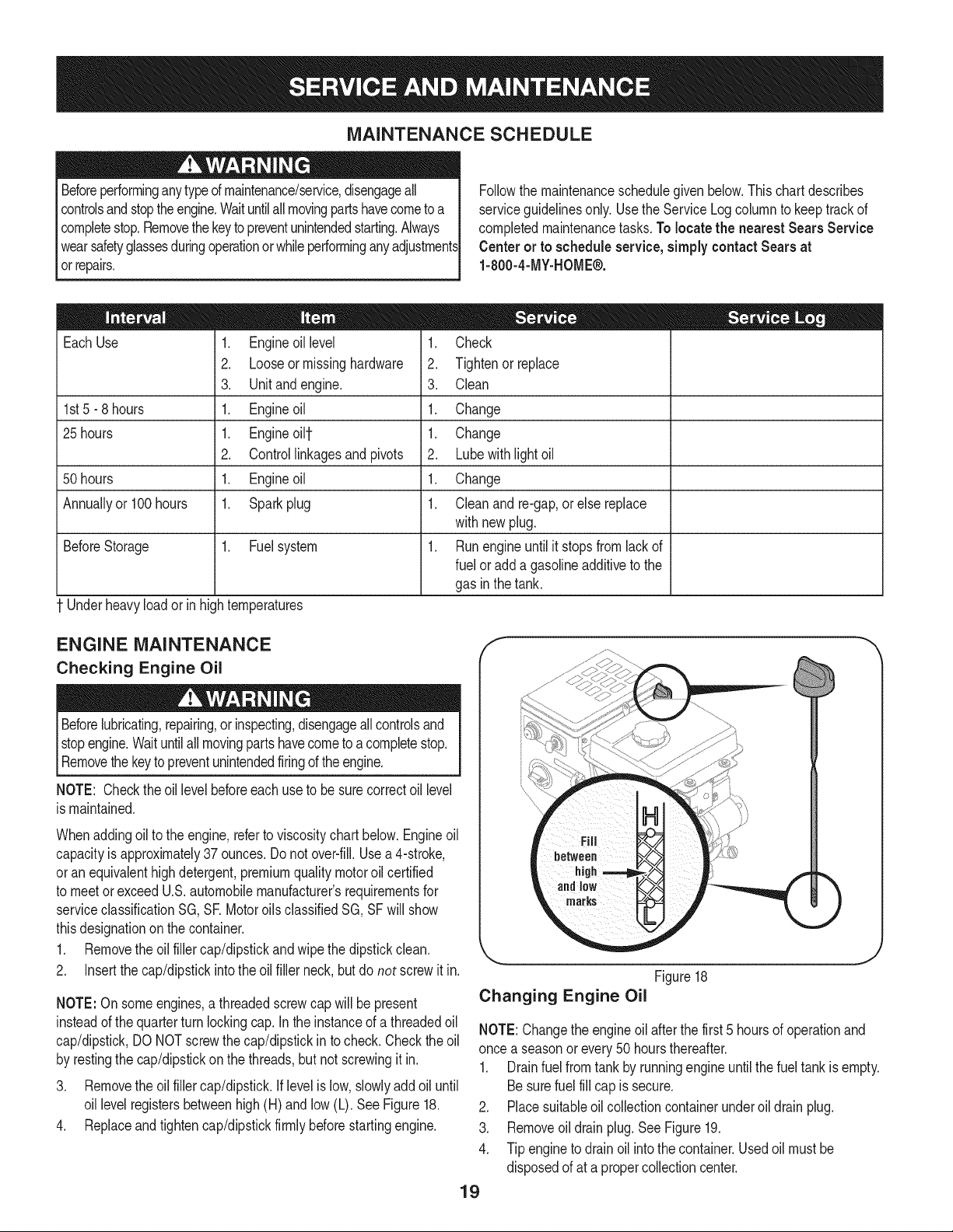
MAINTENANCE SCHEDULE
Beforeperforminganytypeofmaintenance/service,disengageall
controlsandstoptheengine.Waituntilallmovingpartshavecometo a
completestop.Removethekeytopreventunintendedstarting.Always
wearsafetyglassesduringoperationorwhileperforminganyadjustments
orrepairs.
EachUse
1st5 - 8 hours
25 hours
50 hours
Annuallyor100hours
1. Engineoillevel
2. Looseormissinghardware
3. Unitandengine.
1. Engineoil
1. Engineoi11-
2. Controllinkagesand pivots
1. Engineoil
1. Sparkplug
1. Check
2. Tightenor replace
3. Clean
1. Change
1. Change
2. Lubewithlightoil
1. Change
1. Cleanand re-gap,orelse replace
withnewplug.
BeforeStorage 1. Fuelsystem
1. Runengineuntilit stopsfromlackof
fueloradda gasolineadditivetothe
gasin thetank.
Underheavyloador inhightemperatures
Followthemaintenanceschedulegivenbelow.Thischartdescribes
serviceguidelinesonly.UsetheServiceLogcolumnto keeptrackof
completedmaintenancetasks.To locate the nearest Sears Service
Centeror toscheduleservice,simplycontactSears at
1-800-4-MY-HOME®.
= =
ENGINE MAINTENANCE
Checking Engine Oil
Beforelubricating,repairing,or inspecting,disengageallcontrolsand
stopengine.Waituntilallmovingpartshavecometoa completestop.
Removethekeyto preventunintendedfiringoftheengine.
NOTE: Checktheoil levelbeforeeachuseto besurecorrectoil level
ismaintained.
Whenaddingoilto theengine,referto viscositychart below.Engineoil
capacityisapproximately37 ounces.Donot over-fill.Usea4-stroke,
oran equivalenthighdetergent,premiumqualitymotoroilcertified
tomeetorexceedU.S.automobilemanufacturer'srequirementsfor
serviceclassificationSG,SR MotoroilsclassifiedSG,SFwill show
thisdesignationonthe container.
1. Removetheoilfillercap/dipstickandwipethedipstickclean.
2. Insertthe cap/dipstickintotheoil fillerneck,butdo not screwit in.
NOTE:On someengines,athreadedscrewcap willbepresent
insteadofthequarterturn lockingcap.Inthe instanceof a threadedoil
cap/dipstick,DONOTscrewthecap/dipstickin tocheck.Checktheoil
byrestingthe cap/dipstickonthe threads,butnotscrewingitin.
3. Removetheoilfillercap/dipstick,iflevelislow,slowlyaddoiluntil
oil levelregistersbetweenhigh(H)andlow(L).SeeFigure18.
4. Replaceandtightencap/dipstickfirmlybeforestartingengine.
J
Figure18
Changing Engine Oil
NOTE:Changetheengineoil afterthefirst5 hoursofoperationand
oncea seasonorevery50 hoursthereafter.
1. Drainfuelfromtankbyrunningengineuntilthefuel tankisempty.
Besurefuel fillcapis secure.
2. Placesuitableoilcollectioncontainerunderoil drainplug.
3. Removeoil drainplug.SeeFigure19.
4. Tipengineto drainoil intothe container.Usedoil mustbe
disposedofat a propercollectioncenter.
19
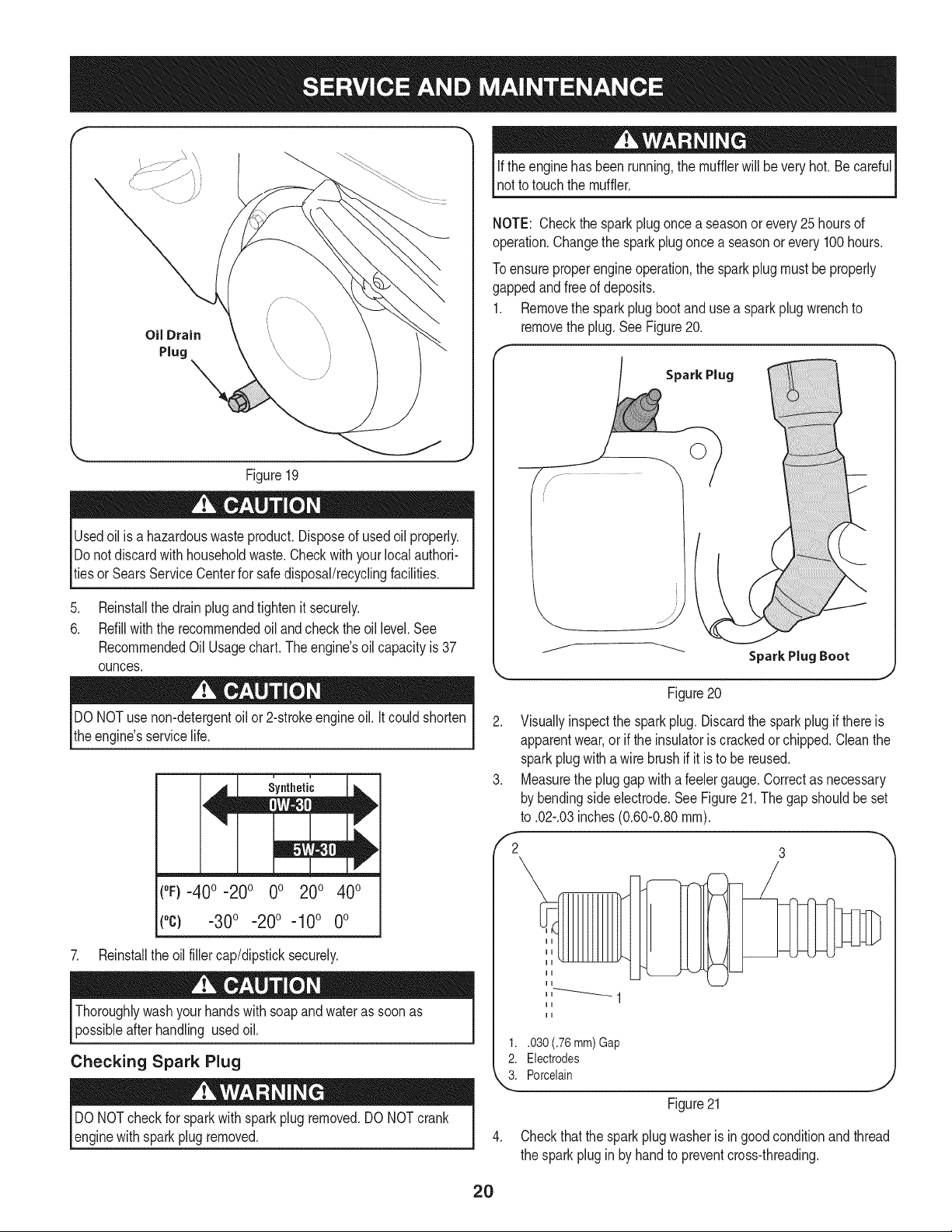
f
Oil Drain
Plug
Figure19
Usedoilisa hazardouswasteproduct.Disposeof usedoilproperly.
Donotdiscardwith householdwaste.Checkwithyourlocalauthori-
tiesor SearsServiceCenterfor safedisposal/recyclingfacilities.
ifthe enginehasbeenrunning,themufflerwillbeveryhot.Becareful
notto touchthemuffler.
NOTE: Checkthesparkplugonce a seasonorevery25hoursof
operation.Changethe sparkplugoncea seasonorevery100hours.
Toensureproperengineoperation,the sparkplugmustbeproperly
gappedandfreeof deposits.
1. Removethesparkplugbootand useasparkplugwrenchto
removetheplug.SeeFigure20.
Spark Plug
.
Reinstallthedrainplugandtightenit securely.
6.
Refillwiththerecommendedoil andchecktheoil level.See
RecommendedOil Usage chart. The engine's oilcapacity is 37
ounces.
DONOTuse non-detergentoilor 2-strokeengineoil.Itcouldshorten
theengine'sservicelife.
(°F}=40o =20o 0o 200 400
(°c) -30° -20° -10° 0°
7. Reinstalltheoilfillercap/dipsticksecurely.
Thoroughlywashyour handswithsoapandwaterassoonas
possibleafterhandling usedoil.
Checking Spark Plug
DONOTcheckforsparkwithsparkplugremoved.DO NOTcrank
enginewithsparkplugremoved.
Figure20
2. Visuallyinspectthe sparkplug.Discardthe sparkplugif thereis
apparentwear,orif theinsulatoriscrackedorchipped.Cleanthe
sparkplugwithawirebrushifit istobe reused.
3. Measurethepluggapwitha feelergauge.Correctasnecessary
bybendingsideelectrode.SeeFigure21.Thegapshouldbeset
to .02-.03inches(0.60-0.80ram).
,'2 3
1..030 (.76 mm) Gap
2. Electrodes
k"_i Porcelain
Figure21
4. Checkthatthesparkplugwasheris ingoodconditionandthread
thesparkpluginby handtopreventcross-threading.
2O

5. Afterthe sparkplugisseated,tightenwithasparkplugwrenchto
compressthewasher.
NOTE:Wheninstallinga newsparkplug,tighten1/2-turnafterthe
sparkplugseatsto compressthe washer.Whenreinstallinga used
sparkplug,tighten1/8-to 1/4-turnafterthesparkplugseatsto
compressthewasher.
hotandcan ine.
CARBURETOR ADJUSTMENT
Thecarburetoris notuseradjustable.ContactSearsParts& Repairfor
adjustment.
LUBRICATION
Drive and Shifting Mechanism
Atleastoncea seasonor afterevery25 hoursofoperation,remove
rearcover.Lubricateall chains,sprockets,gears,bearings,shafts,and
theshiftingmechanism.Useengineoilora spraylubricant.Referto
Figure22.
NOTE:Beforetippingtheunitonthe fronthousing,runthefueltank
emptyso fueldoes notleak outof thefuelcap.
1. Carefullypivotthesnowthrowerupandforwardsothat it restson
theaugerhousing.
2. Removetheframecoverfromtheundersideof thesnowthrower
byremovingtheself-tappingscrewswhichsecureit. Referto
Figure27.
3. Applya lightcoatingof engineoil (or3-in-1oil) tothe hexshaft.
SeeFig.22.
NOTE:Becarefulnottoget anyoilon thealuminumdrive plateor
rubberfrictionwheel.Doingsowill hinderthesnowthrower'sdrive
system.Wipeoff anyexcessorspilledoil.
4. At least once a season grease the wheel axle with Arctic grease,
part number 737-0318. The grease fitting is located on the
wheel axle tube behind the wheel axle support bracket.
Wheels
At leastoncea season,removebothwheels.Cleanandcoattheaxles
witha multipurposeautomotivegreasebeforereinstallingwheels.
Chute Directional Control
Onceaseason,lubricatethe eyebolt bushingandthe spiralwith3-in-1
oil.
Auger Shaft
At leastoncea season,oneat a time,removeallof theshearpins
fromthe augershaft.Spraylubricantinsidethehubof eachauger
spiralassemblyandaroundthe spacersonthe augershaft.
Greasefittingscan alsobe foundateach endofthe augershaft.
Lubricatewitha greasegunoncea season.SeeFigure23.
Gear Case
Theaugergearcaseis equippedwitha greasefitting.Lubricatewith
greaseoncea season(orderpartnumber737-0168).SeeFigure6-2.
NOTE:Torelievepressure,removetheventplugbeforelubricatingthe
gearcase.See Figure23. Failuretodoso couldresultindamageto
thegearcaseseals.
Augers
Eachoftheaugerspiralassembliesis securedtothe spiralshaftwith
a shearpinandcotter pin.If the augershouldstrikeaforeignobjector
icejam,the snowthrowerisdesignedsothatthe pinsmayshear.
1. Ifaugersdonot turn,checkto seeif pinshavesheared.
2. Replacethepinsif needed.Tworeplacementshearpinsand
cotterpins havebeenprovidedwiththe snowthrower.Sprayan
oil lubricantintoshaft beforeinsertingnewpinsand securingwith
newcotter pins.See Fig.23.
i • i I ii
i Shear Pins ii:i
" Vent Plug Grease Fitting
Aluminum
Drive
Wheel Axle
Support Bracket
/ .............
Bow=Tie Pins Spacers
Figure23
Figure22
21
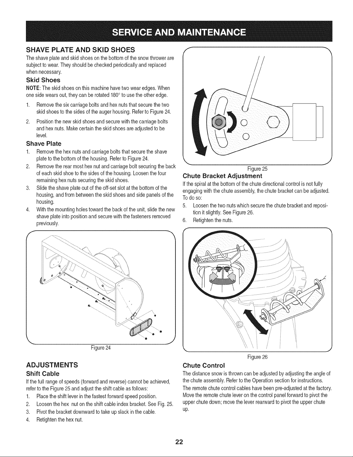
SHAVE PLATE AND SKiD SHOES
Theshaveplateand skidshoesonthebottomofthesnowthrowerare
subjectto wear.Theyshouldbecheckedperiodicallyandreplaced
whennecessary.
Skid Shoes
NOTE:Theskidshoesonthismachinehavetwowearedges.When
onesidewearsout, theycan be rotated1800to usethe otheredge.
1. Removethesix carriageboltsandhexnutsthatsecurethetwo
skidshoestothe sidesofthe augerhousing.RefertoFigure24.
2. Positionthenew skidshoesandsecurewiththecarriagebolts
andhexnuts.Makecertaintheskidshoesare adjustedtobe
level.
Shave Plate
1. Removethehexnutsandcarriageboltsthatsecuretheshave
plateto thebottomofthe housing.Referto Figure24.
2. Removetherearmosthexnutand carriageboltsecuringtheback
ofeachskidshoeto thesidesof thehousing.Loosenthefour
remaininghexnutssecuringthe skidshoes.
3. Slidetheshaveplateoutof theoff-setslotat thebottomofthe
housing,andfrombetweenthe skidshoesandsidepanelsofthe
housing.
4. Withthemountingholestowardthebackof theunit,slidethenew
shaveplateinto positionandsecurewiththe fastenersremoved
previously.
f
k
J
Figure25
Chute Bracket Adjustment
Ifthespiralatthe bottomof thechutedirectionalcontrolis notfully
engagingwiththechuteassembly,the chutebracketcanbeadjusted.
Todo so:
5. Loosenthetwo nutswhichsecurethechutebracketandreposi-
tionit slightly.SeeFigure26.
6. Retightenthenuts.
0
Figure24
ADJUSTMENTS
Shift Cable
If thefull rangeofspeeds(forwardandreverse)cannotbe achieved,
referto theFigure25 andadjusttheshiftcableas follows:
1. Placethe shiftleverin thefastestforwardspeedposition.
2. Loosenthehex nutontheshiftcableindexbracket.SeeFig.25.
3. Pivotthebracketdownwardtotakeupslack inthecable.
4. Retightenthehexnut.
Figure26
Chute Control
Thedistancesnowisthrowncanbe adjustedbyadjustingtheangleof
thechuteassembly.Referto theOperationsectionforinstructions.
Theremotechutecontrolcableshavebeenpre-adjustedatthefactory.
Movethe remotechuteleveronthecontrolpanelforwardtopivotthe
upperchutedown;movetheleverrearwardtopivottheupperchute
up.
22

Wheel drive control
Refertothe Adjustmentsectionofthe Assemblyinstructionsto adjust
thewheeldrivecontrol.Tofurtherchecktheadjustment,proceedas
follows:
1. Withthe snowthrowertippedforward(becertainto runthe
fueltankdry beforetippingtheunitforward),removetheframe
coverunderneaththesnowthrowerby removingtheself-tapping
screws.SeeFig.27.
J
Figure27
Auger Control
RefertotheAssemblysectionforinstructionson adjustingtheauger
controlcable.
Skid Shoes
RefertotheAssemblysectionforinstructionson adjustingtheskid
shoes.
Tire Pressure
RefertotheAssemblysectionforinstructionson adjustingthetire
pressure.
BELT REPLACEMENT
Belt Removal Preparation
1. Removethechutecrankrodfromthechutecrankassemblyby
removingthehairpinclip shownin Fig.29.Movethechutecrank
rodawayfromtheassemblyas shown.
Removethreeself-tapscrewson bothsidesof thetransmission
housingas shownin Fig.29.
2. Locatetheopeningbetweentheaxlesupportbracketand
thefrontframesupport(SeeFigure28). Lookingthroughthis
opening,withthe wheeldrivecontrolreleased,theremustbe
clearancebetweenthefrictionwheelandthedriveplateinall
positionsofthespeedselectorlever.
3. Withthewheeldrivecontrolengaged,thefrictionwheelmust
contactthedrive plate.SeeFigure28.
Drive -Axle Supp.
Plate Bracket
Opening
Figure29
3. Removethe plasticbeltcover,locatedneartheengine,byremov-
ing thethreeself-tappingscrewsthatsecureit.See Figure30.
f
Figure28
4. Ifthereisnofrictionwheelclearance,or thefrictionwheeldoes
notsolidlycontactthe driveplate,re-adjustthelocknuton the
lowerendof thedrive cablefollowingtheinstructionsin the
Assemblysection.
5. Reassemblethe framecover.
23

.
Loosentheboltshownin Figure31securingthebeltkeeper
bracketandremovetheotherbolt.Pushthebeltkeeperand
bracketupoff the enginepulley.
Loosen
\
\
Figure31
Auger Belt Replacement
1. Removethebow-tieclipandflatwasherfromtheferrulein order
todisconnecttheaugeridlerrodfromthebrakebracketassem-
bly.SeeFigure32.
NOTE:Makesurethatthelocationof theferruleon theauger
idlerrodismaintained.
HairpinClip
Ferrule
AugerIdlerRod
z-fitting
J
Figure33
Placeablockof woodunderneaththeaugerhousingas shownin
Figure34 andseparateaugerhousingfromtheframebytiltingthe
housingforwardandpullingupthehandles.
Figure34
6. Blocktheimpellerwithapieceof woodtopreventit fromspinning
andusea 1/2"wrenchtoremovethe hexscrewandflatwasher
fromthecenterofthepulleyontheaugerhousing.SeeAinFig.35.
7. Liftthebrakebracketassemblyoutofthe pulleygroove(B in
Figure35)andslide thepulleyassemblyoff the postsof theauger
pulleyadapter(C) to removetheoldbelt.
Figure32
2. Sliptheaugercontrolbelt (thefrontbelt) offtheenginepulley.
3. Pullthebrakebracketassemblytowardsthecableguideroller
andunhooktheaugercablez-fitting.SeeFigure33.
4. Frombothsidesof thethe frameassembly,usea1/2"wrenchto
removethethreehextapscrewssecuringthe frametothe auger
housingassembly.Referbackto Figure29.
NOTE:Do notremovethelowerhexflangelocknuton eachside.
24
NOTE:Thepulleyadaptermayslideoff the augerinputshaft
whenremovingthepulley.Useextracautionto ensurethe
adapterdoesfalland/or getdamagedwhen removingthepulley.
.
Placethenewaugerbeltin theV-grooveof theaugerpulleyand
placethepulleyw/belt insidethebeltkeepers.
9.
Turnthepulleyasnecessarytoalignitsthreeslotsapproximately
withthepostsofthepulleyadapter,thenpivotthebrakebracket
assemblyawayfromthepulleygroove. Whilealigningthe pulley
slotsandadapterposts,pushtheaugerpulleyfullyontothe
adapter.RefertoFigure35.Ensurethebrakepuckofthebrake
bracketassemblyalignsandis fullyseatedin thepulleygroove.
Brake
!
pterPost
%
J
Figure35
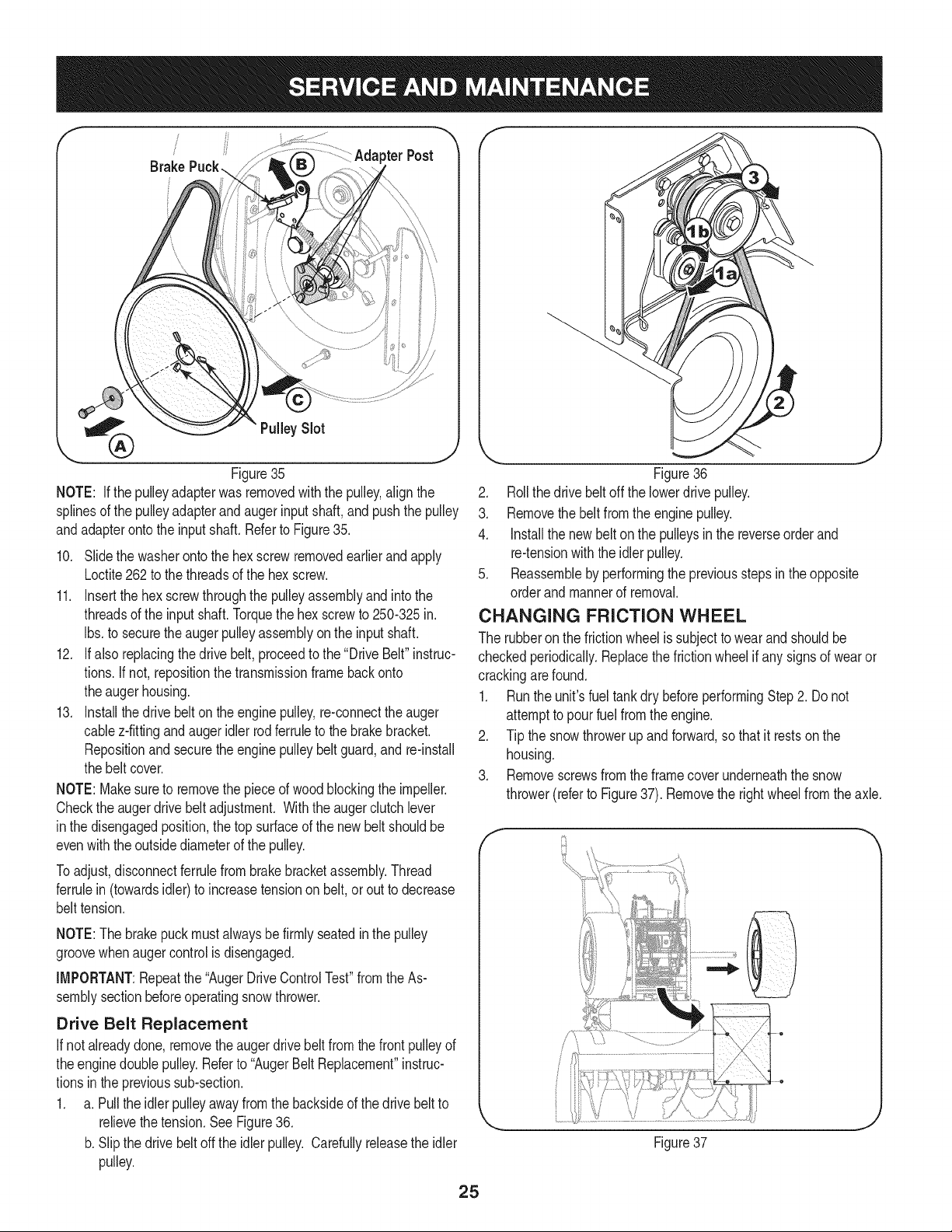
NOTE: If the pulleyadapterwasremovedwiththe pulley,alignthe
splinesofthe pulleyadapterandaugerinputshaft,andpushthepulley
andadapterontotheinputshaft.Referto Figure35.
10. Slidethewasherontothehexscrewremovedearlierandapply
Loctite262to thethreadsofthehexscrew.
11. Insertthehexscrewthroughthepulleyassemblyandintothe
threadsofthe inputshaft.Torquethehex screwto250-325in.
Ibs.to securetheaugerpulleyassemblyon the inputshaft.
12. Ifalsoreplacingthedrivebelt,proceedtothe"DriveBelt"instruc-
tions.If not,repositionthetransmissionframebackonto
theaugerhousing.
13. Installthedrivebelton theenginepulley,re-connecttheauger
cablez-fittingandaugeridler rodferruletothe brakebracket.
Repositionand securetheenginepulleybeltguard,and re-install
thebeltcover.
NOTE:Makesureto removethepieceof woodblockingthe impeller.
Checktheaugerdrivebeltadjustment.Withthe augerclutchlever
inthedisengagedposition,thetopsurfaceofthenewbeltshouldbe
evenwiththeoutsidediameterofthe pulley.
Toadjust,disconnectferrulefrombrakebracketassembly.Thread
ferrulein(towardsidler)toincreasetensiononbelt,orouttodecrease
belttension.
J
Figure36
2. Rollthedrivebeltoff thelowerdrivepulley.
3. Removethe beltfromthe enginepulley.
4. Installthe newbelton thepulleysinthe reverseorderand
re-tensionwiththeidlerpulley.
5. Reassemblebyperformingthe previousstepsintheopposite
orderand mannerofremoval.
CHANGING FRICTION WHEEL
Therubberonthe frictionwheelissubjecttowearandshouldbe
checkedperiodically.Replacethefrictionwheelifanysignsofwearor
crackingarefound.
1. Runthe unit'sfuel tankdry beforeperformingStep2. Donot
attempttopourfuel fromtheengine.
2. Tipthe snowthrowerupand forward,sothat it restsonthe
housing.
3. Removescrewsfromtheframecoverunderneaththesnow
thrower(referto Figure37).Removetherightwheelfromtheaxle.
NOTE:Thebrakepuckmustalwaysbefirmly seatedinthepulley
groovewhenaugercontrolisdisengaged.
IMPORTANT:Repeatthe"AugerDriveControlTest"fromthe As-
semblysectionbeforeoperatingsnowthrower.
Drive Belt Replacement
If notalreadydone,removetheaugerdrivebelt fromthefrontpulleyof
theenginedoublepulley.Referto "AugerBeltReplacement"instruc-
tionsintheprevioussub-section.
1. a.Pullthe idlerpulleyawayfromthe backsideofthedrivebeltto
relievethetension.SeeFigure36.
b.Slipthe drivebelt offtheidlerpulley.Carefullyreleasetheidler
pulley.
e
Figure37
25
 Loading...