

Craftsman 247888350 Owner’s Manual
Operator's Manual
P R 0 F E S S I 0 N A L
33" SNOW THROWER
Model No. 247.88835
, SAFETY
, ASSEMBLY
, OPERATION
, MAINTENANCE
CAUTION: Before using
this product, read this
, PARTS LIST
o ESPANOL
manual and follow all
safety rules and operating
instructions.
Sears Brands Management Corporation, Hoffman Estates, IL 60179, U.S.A.
Visit our website: www.craftsman.com FORM1/0.769-04980C
6/23/2011
WarrantyStatement..................................Page2
SafeOperation Practices .......................... Page 3
Safety Labels ............................................ Page 7
Assembly .................................................. Page 8
Operation .................................................. Page 13
Service and Maintenance ......................... Page 18
Off-Season Storage .................................. Page 26
Troubleshooting ........................................ Page 27
Parts List ................................................... Page 28
Repair Protection Agreement ................... Page 39
Espa_ol ..................................................... Page 40
Service Numbers ...................................... Back Cover
CRAFTSMAN PROFESSIONAL TWO YEAR FULL WARRANTY
FORTWOYEARSfromthedateofpurchase,this productiswarrantedagainstanydefectsin materialor workmanship.A defectiveproductwill
receivefreerepairor replacementif repairisunavailable.
Thiswarrantyappliesforonlyone yearfromthedateof purchaseifthis productis everusedwhileprovidingcommercialservicesor if rentedto
anotherperson.
Forwarrantycoveragedetailsto obtainfreerepairorreplacement,visitthe web site:www.craftsman.com
Thiswarranty coversONLYdefects in material andworkmanship. Warrantycoverage does NOTinclude:
• Expendableitemsthatcanwearoutfromnormalusewithinthewarrantyperiod,includingbutnotlimitedtoaugers,augerpaddles,drift
cutters,skidshoes,shaveplate,shearpins,sparkplug,air cleaner,belts,andoilfilter.
• Standardmaintenanceservicing,oilchanges,or tune-ups.
• Tire replacementor repaircausedby puncturesfromoutsideobjects,suchas nails,thorns,stumps,or glass.
• Tireorwheelreplacementor repairresultingfromnormalwear,accident,orimproperoperationor maintenance.
• Repairsnecessarybecauseof operatorabuse,includingbutnotlimitedtodamagecausedbyover-speedingtheengine,orfromimpacting
objectsthatbendtheframe,augershaft,etc.
• Repairsnecessarybecauseof operatornegligence,includingbutnotlimitedto,electricalandmechanicaldamagecausedbyimproper
storage,failureto usethe propergradeandamountofengineoil,or failureto maintaintheequipmentaccordingtotheinstructionscontained
intheoperator'smanual.
• Engine(fuelsystem)cleaningorrepairscausedbyfueldeterminedto becontaminatedoroxidized(stale).In general,fuelshouldbeused
within30 daysof itspurchasedate.
• Normaldeteriorationandwearof the exteriorfinishes,orproductlabelreplacement.
Thiswarrantygivesyouspecificlegalrights,andyou mayalso haveotherrightswhichvaryfromstatetostate.
Sears Brands Management Corporation, Hoffman Estates, IL 60179
EngineOilType: 5W-30
EngineOilCapacity: 37ounces
FuelCapacity: Approx.5 Quarts
SparkPlug: F6RTC(951-10292)
SparkPlugGap: .020"to.030"
©KCDIR LLC
ModelNumber.................................................................
Serial Number .................................................................
Dateof Purchase.............................................................
Recordthemodelnumber,serialnumber
anddateof purchaseabove
2
Thissymbolpointsoutimportantsafetyinstructionswhich,if not
followed,couldendangerthepersonalsafetyand/orpropertyof
yourselfandothers. Readandfollowall instructionsin thismanual
beforeattemptingto operatethismachine.Failuretocomplywith
theseinstructionsmayresultin personalinjury.Whenyou seethis
symbol,HEEDITSWARNING!
Thismachinewasbuiltto beoperatedaccordingtothesafeopera-
tionpracticesinthis manual.Aswithanytypeof powerequipment,
carelessnessorerroron thepartof the operatorcanresultin serious
injury.Thismachineiscapableofamputatingfingers,hands,toes
andfeetandthrowingdebris.Failuretoobservethefollowingsafety
instructionscouldresultin seriousinjuryor death.
CALIFORNIA PROPOSITION 65
EngineExhaust,someof itsconstituents,andcertainvehicle
componentscontainoremitchemicalsknownto Stateof California
tocausecancerandbirthdefectsorotherreproductiveharm,
TRAiNiNG
• Read,understand,andfollowall instructionson the machineand
in themanual(s)beforeattemptingtoassembleandoperate.
Failuretodo socan resultinseriousinjurytothe operatorand/
orbystanders.Keepthismanualina safeplaceforfutureand
regularreferenceandfororderingreplacementparts.
• Befamiliarwithall controlsandtheirproperoperation.Knowhow
tostopthemachineanddisengagethemquickly.
• Neverallowchildrenunder14yearsof agetooperatethis
machine.Children14andovershouldreadandunderstandthe
instructionsandsafeoperationpracticesinthismanualandon
themachineandbe trainedandsupervisedbyanadult.
Neverallowadultsto operatethis machinewithoutproper
instruction.
• Thrownobjectscancauseseriouspersonalinjury.Planyour
snow-throwingpatterntoavoiddischargeof materialtoward
roads,bystandersandthelike.
Keepbystanders,petsandchildrenat least75feetfromthe
machinewhileitisin operation.Stopmachineifanyoneenters
thearea.
• Exercisecautiontoavoidslippingor falling,especiallywhen
operatinginreverse.
Your Responsibility--Restrict theuseof thispowermachineto
personswhoread,understandandfollowthewarningsand instruc-
tionsin thismanualandon themachine.
SAVE THESE INSTRUCTIONS!
PREPARATION
Thoroughlyinspecttheareawheretheequipmentisto beused.
Removeall doormats,newspapers,sleds,boards,wiresandother
foreignobjects,whichcouldbe trippedoverorthrownbytheauger/
impeller.
• Alwayswearsafetyglassesoreyeshieldsduringoperationand
whileperformingan adjustmentor repairto protectyoureyes.
Thrownobjectswhichricochetcancauseseriousinjurytothe
eyes.
Donot operatewithoutwearingadequatewinteroutergarments.
Donot wearjewelry,longscarvesorotherlooseclothing,which
couldbecomeentangledinmovingparts.Wearfootwearwhich
willimprovefootingonslipperysurfaces.
Usea groundedthree-wireextensioncordand receptaclefor all
machineswithelectricstartengines.
Disengageall controlleversbeforestartingtheengine.
Adjustcollectorhousingheighttocleargravelorcrushedrock
surfaces.
• Neverattempttomakeanyadjustmentswhileengineis running,
exceptwherespecificallyrecommendedinthe operator'smanual.
Letengineandmachineadjusttooutdoortemperaturebefore
startingtoclearsnow.
3
SafeHandlingof Gasoline
Toavoidpersonalinjuryor propertydamageuseextremecarein
handlinggasoline.Gasolineisextremelyflammableandthevaporsare
explosive.Seriouspersonalinjurycan occurwhengasolineisspilled
onyourselforyourclotheswhichcan ignite.Washyourskinand
changeclothesimmediately.
• Useonlyanapprovedgasolinecontainer.
• Extinguishall cigarettes,cigars,pipesandother sources
ofignition.
• Neverfuelmachineindoors.
• Neverremovegascapor addfuelwhiletheengineishot
or running.
• Allowengineto coolat leasttwo minutesbeforerefueling.
• Neveroverfill fueltank.Filltankto no morethan1/2inch
belowbottomoffillerneckto providespaceforfuel
expansion.
• Replacegasolinecapandtightensecurely.
• Ifgasolineisspilled,wipeit offtheengineandequipment.
Movemachinetoanotherarea.Wait5 minutesbefore
startingtheengine.
• Neverstorethemachineor fuel containerinsidewhere
thereis anopenflame,sparkor pilotlight (e.g.furnace,
waterheater,spaceheater,clothesdryeretc.).
• Allowmachinetocoolatleast5 minutesbeforestoring.
• Neverfillcontainersinsidea vehicleorona truckor trailer
bedwitha plasticliner.Alwaysplacecontainersonthe
groundawayfromyourvehiclebeforefilling.
• If possible,removegas-poweredequipmentfromthetruck
ortrailerand refueliton the ground.If thisisnotpossible,
thenrefuelsuchequipmentona trailerwitha portable
container,ratherthanfromagasolinedispensernozzle.
• Keepthenozzleincontactwiththe rimofthefueltankor
containeropeningatalltimesuntilfuelingis complete.Do
notuse a nozzlelock-opendevice.
OPERATION
• Do not puthandsorfeetnear rotatingparts,in the auger/impeller
housingorchuteassembly.Contactwiththerotatingpartscan
amputatehandsandfeet.
• Theauger/impellercontrolleverisa safetydevice.Neverbypass
itsoperation.Doingsomakesthemachineunsafeandmaycause
personalinjury.
• Thecontrolleversmustoperateeasilyinbothdirectionsand
automaticallyreturntothedisengagedpositionwhenreleased.
• Neveroperatewitha missingordamagedchuteassembly.Keep
all safetydevicesin placeandworking.
• Neverrunanengineindoorsorina poorlyventilatedarea.Engine
exhaustcontainscarbonmonoxide,anodorlessanddeadlygas.
• Do notoperatemachinewhileundertheinfluenceofalcoholor
drugs.
• Mufflerandenginebecomehotandcan causea burn.Do not
touch.Keepchildrenaway.
• Exerciseextremecautionwhenoperatingon orcrossinggravel
surfaces.Stayalertforhiddenhazardsortraffic.
• Exercisecautionwhenchangingdirectionandwhileoperatingon
slopes.Do notoperateonsteepslopes.
• Planyoursnow-throwingpatternto avoiddischargetowards
windows,walls,carsetc.Thus,avoidingpossibleproperty
damageorpersonalinjurycausedbya ricochet.
• Neverdirectdischargeatchildren,bystandersand petsorallow
anyoneinfrontofthemachine.
• Donot overloadmachinecapacitybyattemptingtoclearsnowat
toofastof a rate.
• Neveroperatethismachinewithoutgoodvisibilityorlight.Always
be sureofyourfootingand keepa firmholdon thehandles.Walk,
neverrun.
• Disengagepowerto theauger/impellerwhentransportingor not
in use.
• Neveroperatemachineathightransportspeedson slippery
surfaces.Lookdownand behindand usecarewhenbackingup.
• Ifthemachineshouldstartto vibrateabnormally,stoptheengine,
disconnectthesparkplugwireandgroundit againstthe engine.
Inspectthoroughlyfordamage.Repairanydamagebefore
startingandoperating.
• Disengageall controlleversandstopenginebeforeyouleave
theoperatingposition(behindthehandles).Waituntiltheauger/
impellercomestoa completestopbeforeuncloggingthechute
assembly,makingany adjustments,or inspections.
• Neverputyourhandinthedischargeor collectoropenings.Do
notunclogchuteassemblywhileengineisrunning.Shutoff
engineand remainbehindhandlesuntilall movingpartshave
stoppedbeforeunclogging.
• Useonlyattachmentsandaccessoriesapprovedbythemanufac-
turer(e.g.wheelweights,tirechains,cabsetc.).
• Whenstartingengine,pullcord slowlyuntilresistanceisfelt,then
pull rapidly.Rapidretractionofstartercord(kickback)willpull
handandarmtowardenginefasterthanyoucanletgo.Broken
bones,fractures,bruisesorsprainscouldresult.
• Ifsituationsoccurwhichare notcoveredinthis manual,usecare
andgoodjudgment.
• Forin-warrantysafety,operationor maintenancequestions,or to
orderpartsandscheduleservice,call 1-800-4-MY-HOME.
CLEARING A CLOGGED DISCHARGE CHUTE
Handcontactwiththe rotatingimpellerinsidethe dischargechute
is themostcommoncauseofinjuryassociatedwithsnowthrowers.
Neveruseyourhandtocleanout thedischargechute.
Toclear thechute:
1. SHUTTHEENGINEOFF!
2. Wait 10secondstobe surethe impellerbladeshavestopped
rotating.
3. Alwaysusea clean-outtool,notyourhands.
4
MAINTENANCE & STORAGE
• Nevertamperwithsafetydevices.Checktheirproperoperation
regularly.Refertothemaintenanceandadjustmentsectionsof
thismanual.
• Beforecleaning,repairing,or inspectingmachinedisengageall
controlleversandstopthe engine.Waituntiltheauger/impeller
cometoa completestop.Disconnectthe sparkplugwireand
groundagainsttheenginetopreventunintendedstarting.
Checkboltsand screwsforpropertightnessatfrequentintervals
tokeepthe machineinsafeworkingcondition.Also,visually
inspectmachineforanydamage.
Donotchangetheenginegovernorsettingorover-speedthe
engine.Thegovernorcontrolsthe maximumsafeoperatingspeed
oftheengine.
Snowthrowershaveplatesandskidshoesaresubjecttowear
anddamage.Foryoursafetyprotection,frequentlycheckall
componentsand replacewithoriginalequipmentmanufacturer's
(OEM)partsonlyas listedinthe Partspagesof thisoperator's
manual.Useofpartswhichdonotmeettheoriginalequipment
specificationsmayleadto improperperformanceandcompro-
misesafety!
Checkcontrolleversperiodicallytoverifytheyengageanddisen-
gageproperlyandadjust,if necessary.Refertotheadjustment
sectioninthisoperator'smanualforinstructions.
Maintainor replacesafetyandinstructionlabels,asnecessary.
Observeproperdisposallawsand regulationsfor gas,oil,etc. to
protecttheenvironment.
Priorto storing,runmachineafew minutestoclear snowfrom
machineand preventfreezeupof auger/impeller.
Neverstorethemachineorfuelcontainerinsidewherethereisan
openflame,sparkorpilot lightsuchas a waterheater,furnace,
clothesdryeretc.
Alwaysrefertotheoperator'smanualforproperinstructionson
off-seasonstorage.
Checkfuelline,tank,cap,andfittingsfrequentlyforcracksor
leaks.Replaceif necessary.
Donotcrankenginewithsparkplugremoved.
AccordingtotheConsumerProductsSafetyCommission(CPSC)
andtheU.S.EnvironmentalProtectionAgency(EPA),thisproduct
hasan AverageUsefulLifeof seven(7)years,or60 hoursof
operation.AttheendoftheAverageUsefulLifehavethemachine
inspectedannuallybyan authorizedservicedealerto ensurethat
allmechanicalandsafetysystemsareworkingproperlyandnot
wornexcessively.Failureto do socanresultinaccidents,injuries
ordeath.
DO NOT MODIFY ENGINE
Toavoidseriousinjuryor death,do notmodifyengineinanyway.
Tamperingwiththegovernorsettingcanleadtoa runawayengineand
causeittooperateat unsafespeeds.Nevertamperwithfactorysetting
ofenginegovernor.
NOTICE REGARDING EMiSSiONS
EngineswhicharecertifiedtocomplywithCaliforniaandfederal
EPAemissionregulationsfor SORE(SmallOffRoadEquipment)are
certifiedto operateon regularunleadedgasoline,and mayinclude
thefollowingemissioncontrolsystems:EngineModification(EM),
OxidizingCatalyst(OC),SecondaryAirInjection(SAI)and ThreeWay
Catalyst(TWO)if so equipped.
SPARK ARRESTOR
Thismachineisequippedwithaninternalcombustionengineand
shouldnotbe usedonor nearanyunimprovedforest-covered,
brush-coveredorgrass-coveredlandunlesstheengine'sexhaust
systemisequippedwitha sparkarrestormeetingapplicablelocalor
statelaws(ifany)
Ifa sparkarrestorisused,itshouldbe maintainedin effectiveworking
orderbytheoperator.Inthe StateofCaliforniatheaboveis required
bylaw (Section4442oftheCaliforniaPublicResourcesCode).Other
statesmayhavesimilarlaws. Federallawsapplyonfederallands.
A sparkarrestorforthemuffleris availablethroughyournearestSears
PartsandRepairServiceCenter.
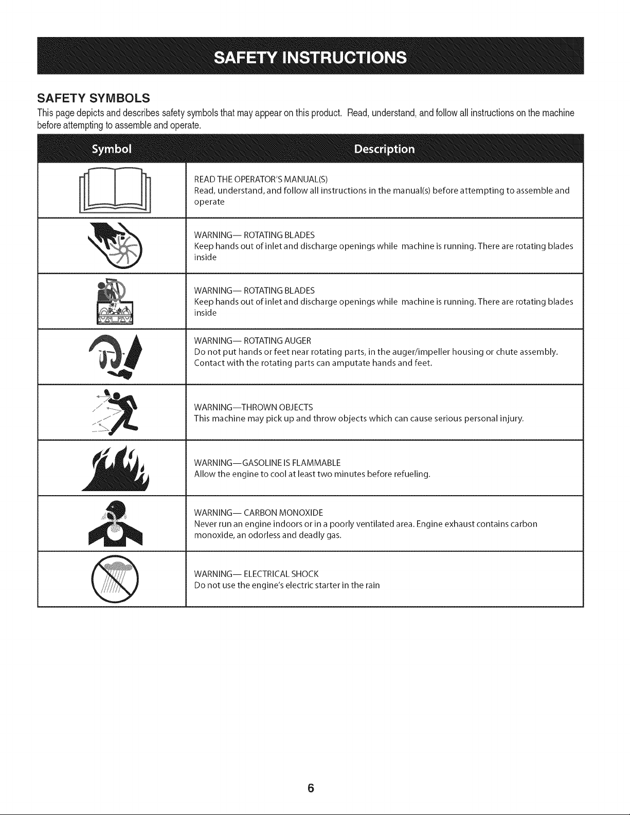
SAFETY SYMBOLS
Thispagedepictsanddescribessafetysymbolsthatmayappearonthisproduct. Read,understand,andfollowall instructionson the machine
beforeattemptingto assembleandoperate.
READ THE OPERATOR'S MANUAL(S)
i
. +
i
Read, understand, and follow all instructions in the manual(s) before attempting to assemble and
operate
WARNING-- ROTATING BLADES
Keep hands out of inlet and discharge openings while machine is running. There are rotating blades
inside
WARNING-- ROTATING BLADES
Keep hands out of inlet and discharge openings while machine is running. There are rotating blades
inside
WARNING-- ROTATING AUGER
Do not put hands or feet near rotating parts, in the auger/impeller housing or chute assembly.
Contact with the rotating parts can amputate hands and feet.
'JIp
WARNING--THROWN OBJECTS
This machine may pick up and throw objects which can cause serious personal injury.
WARNING--GASOLINE IS FLAMMABLE
Allow the engine to cool at least two minutes before refueling.
WARNING-- CARBON MONOXIDE
Never run an engine indoors or in a poorly ventilated area. Engine exhaust contains carbon
monoxide, an odorless and deadly gas+
WARNING-- ELECTRICAL SHOCK
Do not use the engine's electric starter in the rain
6
r
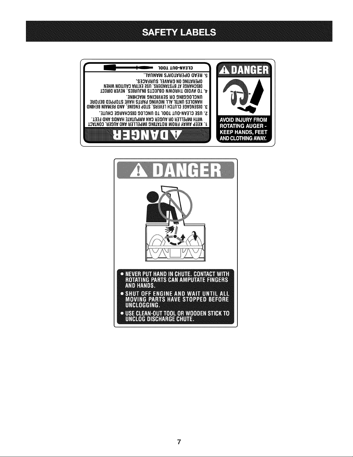
100/.LIIO-NV:IIO
"lVflNV_ S,UOIVU3dOQV3H"G
"S3OV_IJflS]3AVUONO9NIIV_J3dO
N3HMNOIIflVOVSIX]qsfl"S9]ONVIS181V]98VHOSIO
10381083A3N'S]IUflrNI SI03PgoNMOUHIQIOAV01 "_
"3NIHOV_ONIOIA83SUOONIOOO]ONfl
]UO_38O3ddOIS]AVHSlHPd9NIAOW11VlllNfl S]IQNVH
ONIH]8NIVW3UONV']NION]dOlS'88]A]1HOlnlo]9VON]SIO"8
"]lnHg ]gHVHOSIO9010Nfl01 1001lflO-NP]lO ]Sfl "Z
"l]]d ONVSONVH]lPlnd_P NVOH3onvuoHq]l]d_JIHIIM
IOVINO0"u39npONV_J3113dWI9NllVIOU_JOH_IVMVd]3H"L
7
NOTE:Referencesto rightorleftsideofthe snowthroweraredetermined
fromtheoperatingpositionlookingforwardto thefrontofthemachine.
Handle
REMOVING FROM CRATE
1. Removescrewsfromthe bottomofthecratesecuringthesides,
andendsof theshippingcrate.
2. Liftoffthe top off ofthecrateandsetout of the wayofthe
assemblyarea.
3. Removeanddiscardplasticbagthatcoversunit.
4. Removeanyloosepartsincludedwithunit(e.g.,Operator's
Manual,etc.).
5. Pushdownon the lowerhandleand pullunitbackoutofcrate.
6. Makecertainthecratehas beencompletelyemptiedbefore
discardingit.
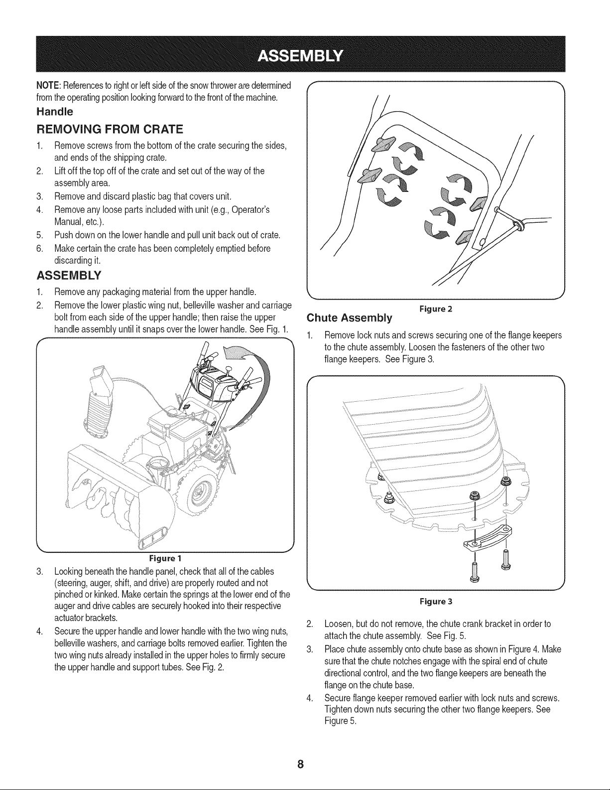
ASSEMBLY
1. Removeanypackagingmaterialfromtheupperhandle.
2. Removethelowerplasticwingnut,bellevillewasherand carriage
boltfromeachsideof the upperhandle;thenraisethe upper
handleassemblyuntilit snapsoverthelowerhandle.SeeFig.1.
_r
Figure 2
,,J
Chute Assembly
1. Removelocknutsandscrewssecuringoneof the flangekeepers
tothechuteassembly.Loosenthefastenersoftheothertwo
flangekeepers. See Figure3.
Figure1
3. Lookingbeneaththehandlepanel,checkthatallofthecables
(steering,auger,shift,anddrive)areproperlyroutedandnot
pinchedorkinked.Makecertainthespringsatthelowerendofthe
augeranddrivecablesaresecurelyhookedintotheirrespective
actuatorbrackets.
4. Securetheupperhandleandlowerhandlewiththetwowingnuts,
bellevillewashers,andcarriageboltsremovedearlier.Tightenthe
twowingnutsalreadyinstalledintheupperholestofirmlysecure
theupperhandleandsupporttubes.SeeFig.2.
\
Figure 3
2. Loosen,butdonotremove,the chutecrankbracketinorderto
attachthe chuteassembly. SeeFig.5.
3. PlacechuteassemblyontochutebaseasshowninFigure4. Make
surethatthechutenotchesengagewiththespiralendof chute
directionalcontrol,andthetwoflangekeepersarebeneaththe
flangeonthe chutebase.
4. Secureflangekeeperremovedearlierwith locknutsand screws.
Tightendownnutssecuringtheothertwo flangekeepers.See
Figure5.
8
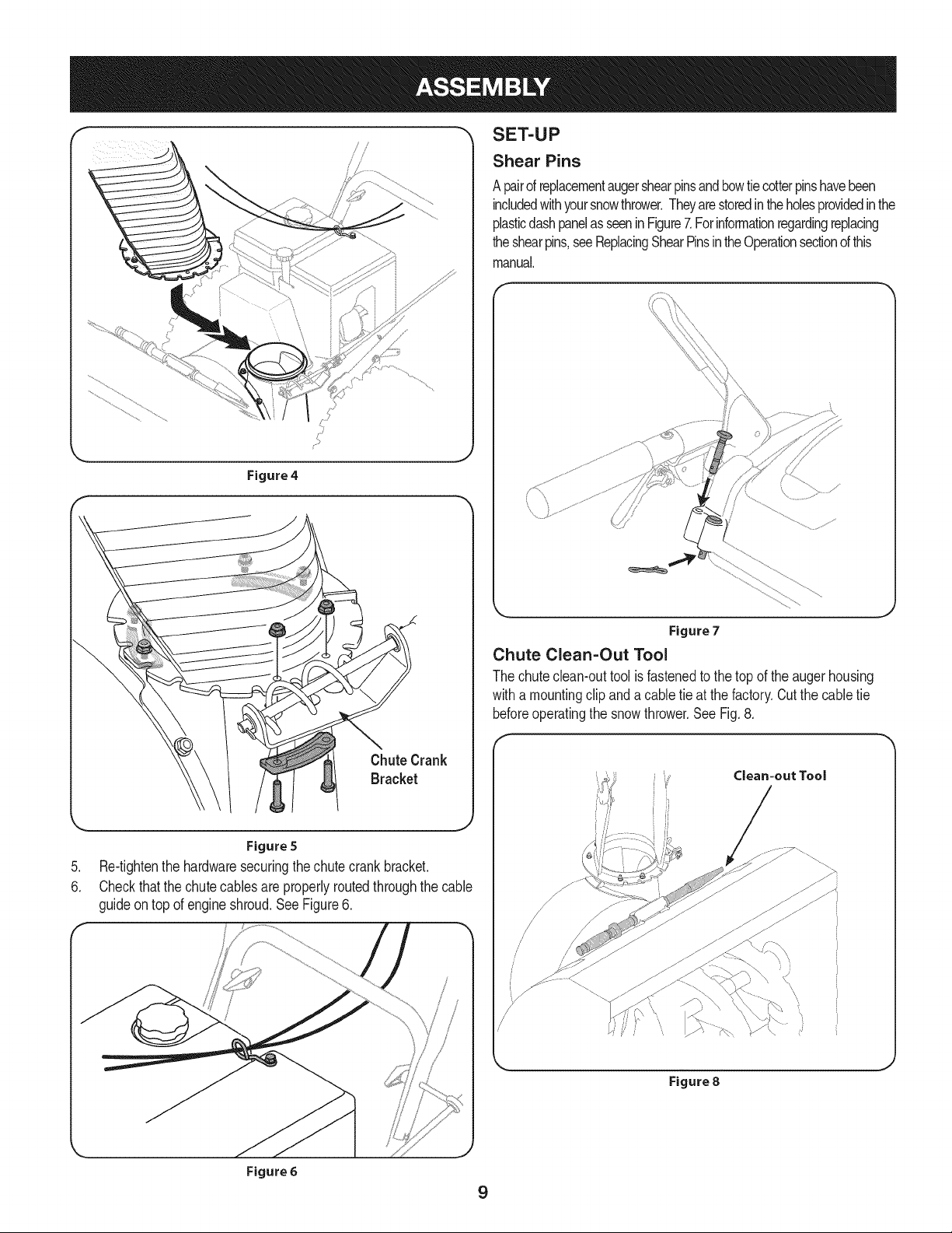
Figure4
SET-UP
Shear Pins
A pairofreplacementaugershearpinsandbowtiecotterpinshavebeen
includedwithyoursnowthrower.Theyarestoredintheholesprovidedinthe
plasticdashpanelas seeninFigure7.Forinformationregardingreplacing
theshearpins,seeReplacingShearPinsintheOperationsectionofthis
manual.
\ \
Figure 5
.
Re-tightenthe hardwaresecuringthechutecrankbracket.
6.
Checkthatthe chutecablesareproperlyroutedthroughthecable
guideontop of engineshroud.SeeFigure6.
Figure7
Chute Clean-Out Tool
Thechuteclean-outtoolisfastenedtothetopoftheaugerhousing
witha mountingclipanda cabletie at the factory.Cutthecabletie
beforeoperatingthe snowthrower.See Fig.8.
/
/
/
/
\
,J
Figure 6
Figure 8
9
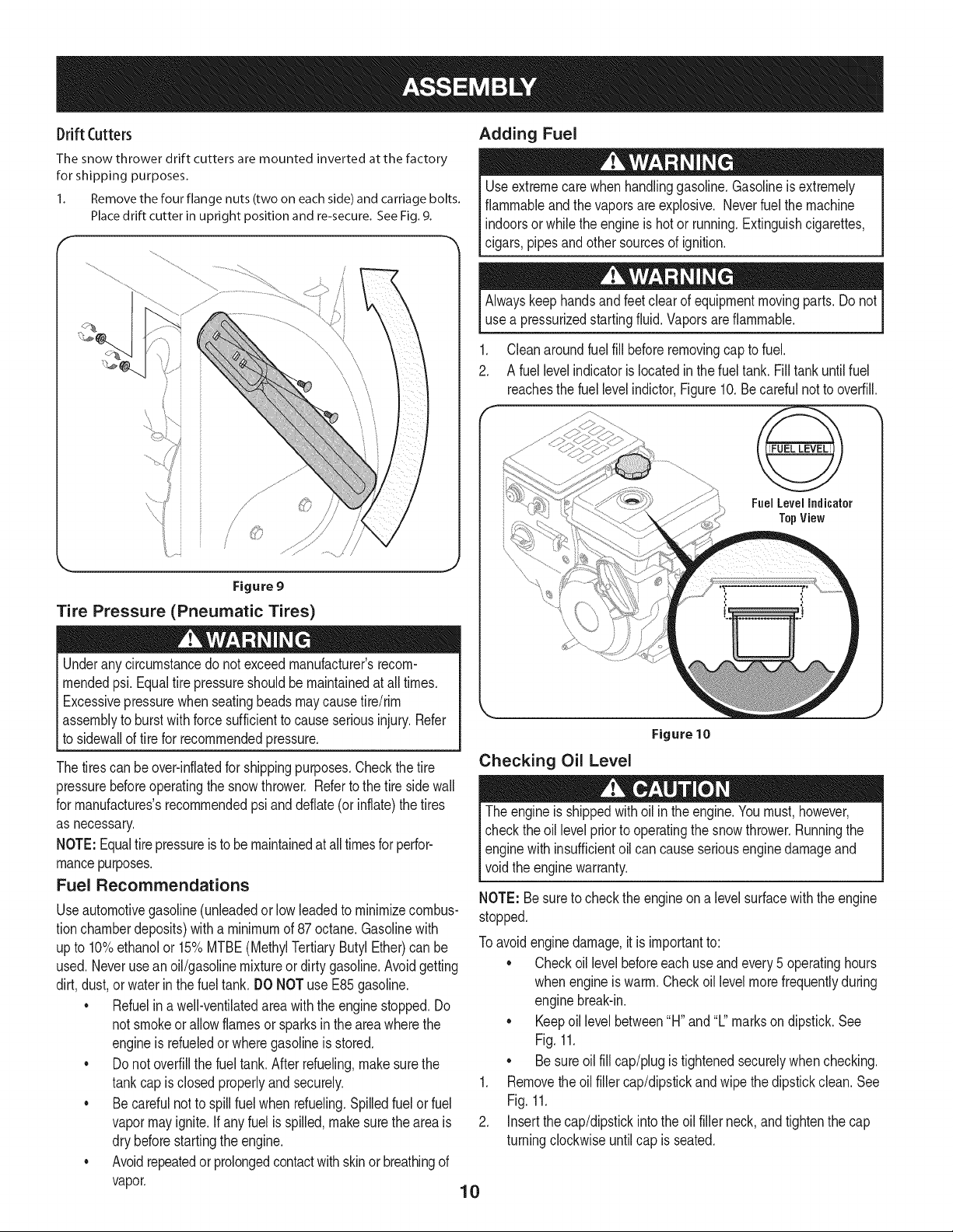
Drift Cutters
The snow thrower drift cutters are mounted inverted at the factory
for shipping purposes.
1. Remove the four flange nuts (two on each side) and carriage bolts.
Place drift cutter in upright position and re-secure. See Fig. 9.
Adding Fuel
Useextremecarewhenhandlinggasoline.Gasolineisextremely
flammableandthe vaporsareexplosive.Neverfuelthemachine
indoorsorwhile theengineis hotor running.Extinguishcigarettes,
cigars,pipesandother sourcesofignition.
Alwayskeephandsandfeetclearofequipmentmovingparts.Donot
usea pressurizedstartingfluid.Vaporsareflammable.
.
Cleanaroundfuel fill beforeremovingcaptofuel.
2.
A fuel levelindicatorislocatedin thefueltank.Fill tankuntilfuel
reachesthefuellevelindictor,Figure10.Becarefulnottooverfill.
Fuel LevelIndicator
TopView
Figure9
Tire Pressure (Pneumatic Tires)
Underanycircumstancedo notexceedmanufacturer'srecom-
mendedpsi.Equaltirepressureshouldbemaintainedatall times.
Excessivepressurewhenseatingbeadsmaycausetire/rim
assemblytoburstwithforcesufficienttocauseseriousinjury.Refer
tosidewallof tirefor recommendedpressure.
Thetirescanbeover-inflatedfor shippingpurposes.Checkthetire
pressurebeforeoperatingthesnowthrower.Refertothetiresidewall
formanufactures'srecommendedpsianddeflate(orinflate)thetires
asnecessary.
NOTE:Equaltirepressureistobemaintainedatalltimesforperfor-
mancepurposes.
Fuel Recommendations
Useautomotivegasoline(unleadedorlowleadedtominimizecombus-
tionchamberdeposits)witha minimumof87octane.Gasolinewith
upto 10%ethanolor 15%MTBE(MethylTertiaryButylEther)canbe
used.Neveruseanoil/gasolinemixtureordirtygasoline.Avoidgetting
dirt,dust,or waterin thefuel tank. DONOTuseE85gasoline.
• Refuelin awell-ventilatedareawiththeenginestopped.Do
notsmokeorallow flamesor sparksin the areawherethe
engineis refueledor wheregasolineisstored.
• Do notoverfillthefueltank.Afterrefueling,makesurethe
tankcapisclosedproperlyandsecurely.
• Becarefulnottospillfuel when refueling.Spilledfuelor fuel
vapormayignite.Ifanyfuelisspilled,makesuretheareais
drybeforestartingtheengine.
• Avoidrepeatedorprolongedcontactwithskinor breathingof
vapor.
J
Figure 10
Checking Oil Level
Theengineisshippedwithoil in theengine.Youmust,however,
checkthe oil levelpriorto operatingthesnowthrower.Runningthe
enginewith insufficientoil cancauseseriousenginedamageand
voidtheenginewarranty.
NOTE:Besuretocheckthe engineon a levelsurfacewiththeengine
stopped.
Toavoidenginedamage,itis importantto:
• Checkoil levelbeforeeachuseandevery5 operatinghours
whenengineiswarm.Checkoil levelmorefrequentlyduring
enginebreak-in.
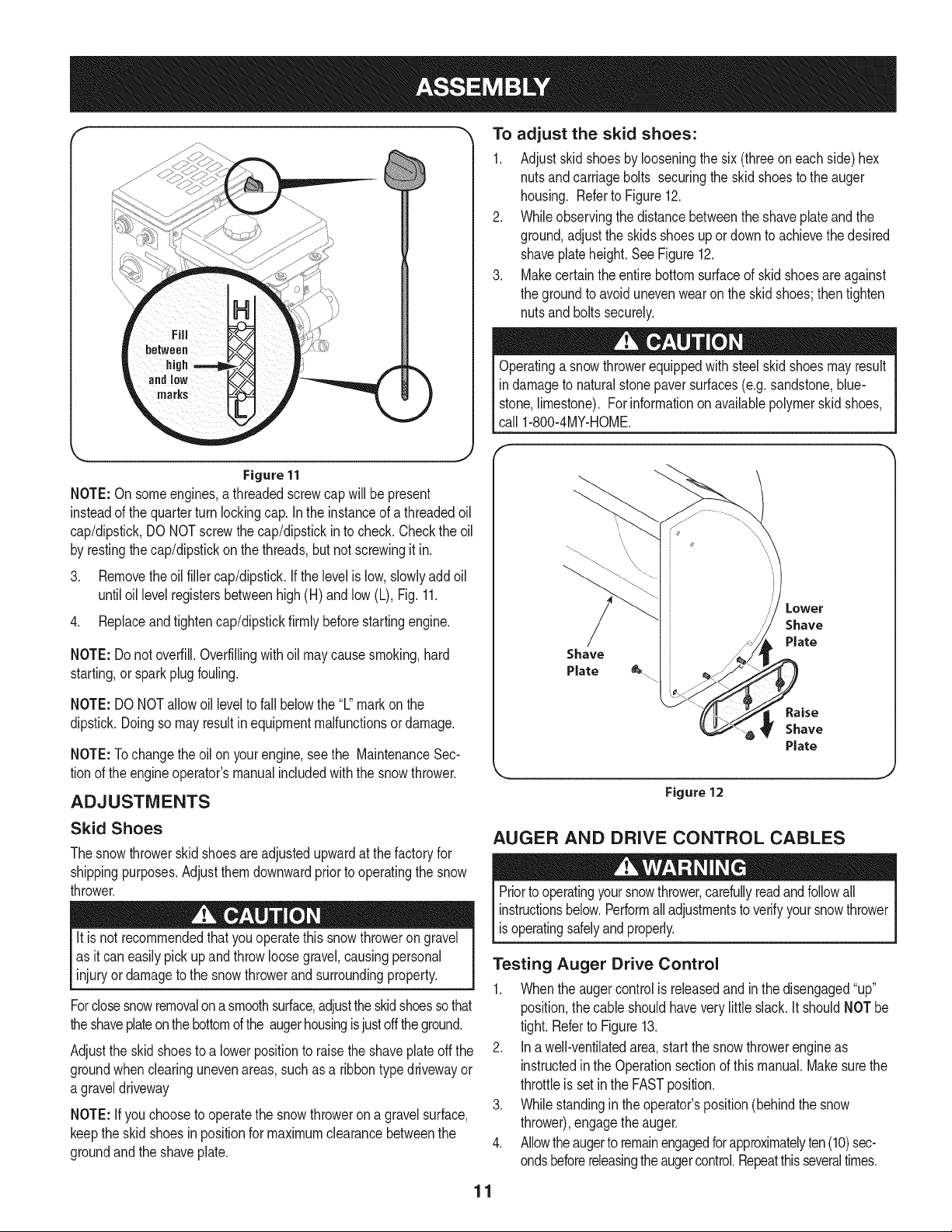
• Keepoillevelbetween"H"and"L"marksondipstick.See
Fig.11.
• Besureoilfill cap/plugis tightenedsecurelywhenchecking.
1. Removetheoilfillercap/dipstickandwipethedipstickclean.See
Fig.11.
2. Insertthecap/dipstickintotheoil fillerneck,andtightenthe cap
turningclockwiseuntilcap is seated.
10
f
Figure11
NOTE:On someengines,athreadedscrewcapwillbepresent
insteadof thequarterturnlockingcap.In the instanceofathreadedoil
cap/dipstick,DONOTscrewthecap/dipstickin tocheck.Checkthe oil
byrestingthecap/dipstickon thethreads,butnotscrewingitin.
3. Removetheoil fillercap/dipstick.Ifthe levelislow,slowlyaddoil
untiloil levelregistersbetweenhigh(H) andlow(L), Fig.11.
4. Replaceandtightencap/dipstickfirmlybeforestartingengine.
NOTE:Donot overfill.Overfillingwithoil maycausesmoking,hard
starting,or sparkplugfouling.
To adjust the skid shoes:
1. Adjustskidshoesbylooseningthesix (threeoneachside)hex
nutsandcarriagebolts securingtheskidshoestotheauger
housing. Referto Figure12.
2. Whileobservingthedistancebetweentheshaveplateandthe
ground,adjustthe skidsshoesupordowntoachievethedesired
shaveplateheight.SeeFigure12.
3. Makecertaintheentirebottomsurfaceofskidshoesareagainst
thegroundtoavoidunevenwearon theskidshoes;then tighten
nutsandboltssecurely.
Operatinga snowthrowerequippedwith steelskidshoesmayresult
indamageto naturalstonepaversurfaces(e.g.sandstone,blue-
stone,limestone).Forinformationonavailablepolymerskidshoes,
call 1-800-4MY-HOME.
/
Shave
Plate
NOTE:DONOTallowoil leveltofallbelowthe"L"markonthe
dipstick.Doingsomayresultin equipmentmalfunctionsordamage.
NOTE:Tochangetheoilon yourengine,seethe MaintenanceSec-
tionof theengineoperator'smanualincludedwiththe snowthrower.
ADJUSTMENTS
Skid Shoes
Thesnowthrowerskidshoesareadjustedupwardat thefactoryfor
shippingpurposes.Adjustthemdownwardpriortooperatingthesnow
thrower.
It is not recommendedthatyouoperatethissnowthrowerongravel
asitcan easilypick upandthrowloosegravel,causingpersonal
injuryor damagetothesnowthrowerandsurroundingproperty.
Forclosesnowremovalona smoothsurface,adjusttheskidshoessothat
theshaveplateonthebottomofthe augerhousingisjustoff theground.
Adjusttheskidshoestoa lowerpositiontoraisetheshaveplateoff the
groundwhenclearingunevenareas,suchas a ribbontypedrivewayor
a graveldriveway
NOTE:Ifyouchoosetooperatethesnowthrowerona gravelsurface,
keepthe skidshoesin positionfor maximumclearancebetweenthe
groundandtheshaveplate.
Figure 12
AUGER AND DRIVE CONTROL CABLES
Priortooperatingyoursnowthrower,carefullyreadandfollowall
instructionsbelow.Performalladjustmentstoverifyyoursnowthrower
isoperatingsafelyandproperly.
Testing Auger Drive Control
1. Whentheaugercontrolisreleasedandinthe disengaged"up"
position,the cable shouldhaveverylittleslack.It shouldNOTbe
tight.RefertoFigure13.
2. Ina well-ventilatedarea,startthesnowthrowerengineas
instructedintheOperationsectionofthis manual.Makesurethe
throttleis setintheFASTposition.
3. Whilestandingin theoperator'sposition(behindthesnow
thrower),engagetheauger.
4. Allowtheaugertoremainengagedforapproximatelyten(10)sec-
ondsbeforereleasingtheaugercontrol.Repeatthisseveraltimes.
11
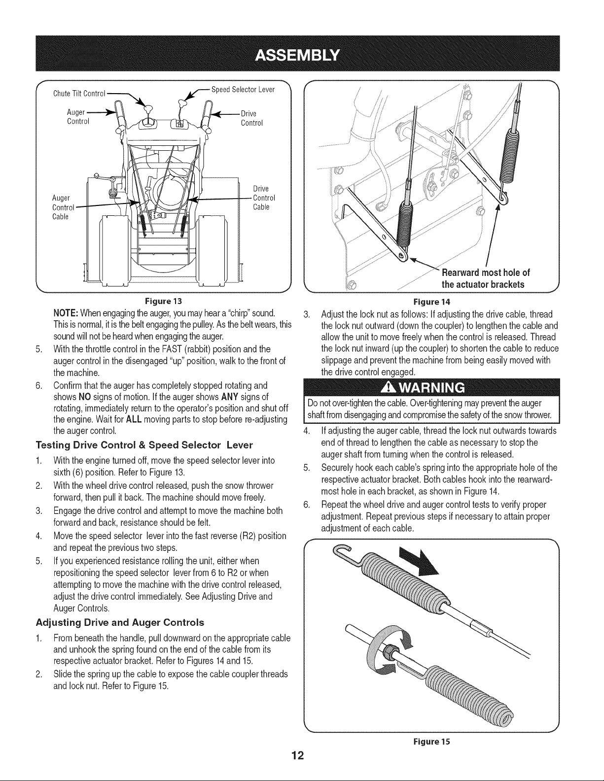
Chut::i: See iil,ever"
Control Control
l I - o ,vo
.liiii o,,!
Figure 13
NOTE:Whenengagingtheauger,youmayheara "chirp"sound.
Thisisnormal,itisthebeltengagingthepulley.Asthebeltwears,this
soundwillnotbeheardwhenengagingtheauger.
5. Withthethrottlecontrolinthe FAST(rabbit)positionandthe
augercontrolin the disengaged"up"position,walktothefrontof
themachine.
6. Confirmthatthe augerhas completelystoppedrotatingand
showsNOsignsof motion,if the augershowsANYsignsof
rotating,immediatelyreturntotheoperator'spositionand shutoff
theengine.WaitforALL movingpartstostopbeforere-adjusting
theaugercontrol.
Testing Drive Control & Speed Selector Lever
1. Withtheengineturnedoff,movethespeedselectorleverinto
sixth(6) position.Referto Figure13.
2. Withthewheeldrivecontrolreleased,pushthe snowthrower
forward,thenpull it back.Themachineshouldmovefreely.
3. Engagethedrivecontroland attemptto movethemachineboth
forwardandback,resistanceshouldbefelt.
4. Movethespeedselector leverinto thefastreverse(R2)position
andrepeattheprevioustwosteps.
5. Ifyou experiencedresistancerollingthe unit,eitherwhen
repositioningthespeedselector leverfrom6 toR2orwhen
attemptingtomovethemachinewiththedrivecontrolreleased,
adjustthedrivecontrolimmediately.SeeAdjustingDriveand
AugerControls.
Adjusting Drive and Auger Controls
1. Frombeneaththehandle,pulldownwardonthe appropriatecable
andunhookthespringfoundonthe endofthecablefromits
respectiveactuatorbracket.RefertoFigures14and 15.
2. Slidethe springupthecable to exposethecablecouplerthreads
andlocknut.Referto Figure15.
Figure14
.
Adjustthe locknutasfollows:if adjustingthedrivecable,thread
thelocknutoutward(downthecoupler)to lengthenthecableand
allowthe unit to movefreelywhenthecontrolis released.Thread
thelocknutinward(upthecoupler)to shortenthe cabletoreduce
slippageandpreventthemachinefrombeingeasilymovedwith
thedrivecontrolengaged.
Donotover-tightenthecable.Over-tighteningmaypreventtheauger
shaftfromdisengagingandcompromisethesafetyofthesnowthrower.
4. Ifadjustingtheaugercable,threadthelock nutoutwardstowards
endofthreadtolengthenthecableasnecessaryto stopthe
augershaftfromturningwhenthecontrolis released.
5. Securelyhookeachcable'sspringintotheappropriateholeofthe
respectiveactuatorbracket.Bothcableshookintothe rearward-
mostholeineachbracket,as shownin Figure14.
6. Repeatthewheeldriveandaugercontrolteststoverifyproper
adjustment.Repeatpreviousstepsifnecessarytoattainproper
adjustmentofeachcable.
12
Figure 15
f
Headlight _eedSelector Lever
FuelTank
FuNCap
0il Fill
When DriveControl
ChutePitch ControP
gerControl
WheelSteeringControl
ChuteAssembly
DriftCutter
Auger
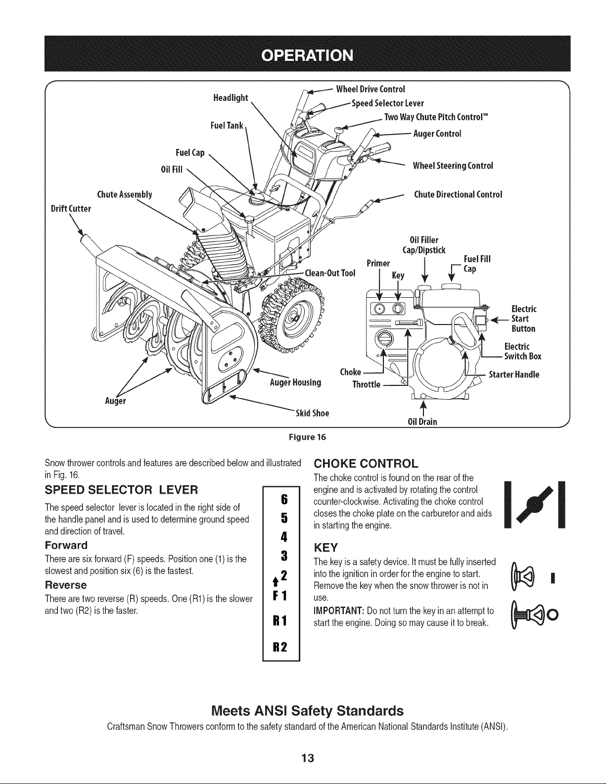
Snowthrowercontrolsandfeaturesaredescribedbelowand
in Fig.16.
SPEED SELECTOR LEVER
Thespeedselector leverislocatedintherightsideof
thehandlepaneland is usedtodeterminegroundspeed
anddirectionoftravel.
Forward
Therearesixforward(F)speeds.Positionone(1)isthe
slowestand positionsix(6) is the fastest.
Reverse
Therearetworeverse(R)speeds.One(R1)is the slower
andtwo(R2) is the faster.
AugerHousing
Figure 16
illustrated
6
5
4
3
t 2
F1
R1
ChuteDirectionalControl
0ilFiller
Cap/Dipstick
FuelFill
Key _ _ =Cap
Electric
Start
Button
Starter Handle
0ilDrain
CHOKE CONTROL
Thechokecontrolisfoundon therearof the
engineand is activatedbyrotatingthecontrol
counter-clockwise.Activatingthechokecontrol
closesthe chokeplateon thecarburetorandaids
instartingtheengine.
KEY
Thekeyisa safetydevice,itmustbefullyinserted
intothe ignitionin orderfor the engineto start.
Removethe keywhenthe snowthroweris not in
use.
iMPORTANT:Donotturn the keyinan attemptto
startthe engine.Doingso maycauseittobreak.
R2
Meets ANSi Safety Standards
CraftsmanSnowThrowersconformtothesafetystandardoftheAmericanNationalStandardsInstitute(ANSI).
13
THROTTLE CONTROL
Thethrottlecontrolis locatedon therearof theengine.It regulatesthe
speedof the engineandwillshutoff the enginewhenmovedintothe
STOPposition.
PRIMER
Pressingtheprimerforcesfueldirectlyintothe
engine'scarburetortoaid in startinga "Cold" qkfP------=---
engine,orrestartingawarmengine. I
OIL FILL
Engineoillevelcanbecheckedandoil added
throughtheoilfill.
OIL DRAIN
Engineoilcanbedrainedthroughtheoil drain.
FUEL CAP
Un-threadthegascap to addgasolinetothefueltank.
MUFFLER
Engineexhaustexiststheengineviathemuffler.
ELECTRIC STARTER OUTLET
Requirestheuseof a three-prongoutdoorextensioncordanda 120V
powersource/walloutlet.
RECOIL STARTER HANDLE
Thishandleisusedto manuallystartthe engine.
ELECTRIC STARTER BUTTON
Pressingtheelectricstarterbuttonengagestheengine'selectric
starterwhenpluggedintoa 120Vpowersource.
AUGER
Whenengaged,theaugerbladesrotateanddrawsnowintotheauger
housing.
CHUTE ASSEMBLY
Snowdrawnintotheaugerhousingisdischargedoutthechute
assembly.
DRIFT CUTTERS
Thedrift cuttersaredesignedforuse indeepsnow.Theiruseis
optionalfornormalsnowconditions.Maneuverthesnowthrowerso
thatthecutterspenetratea highstandingsnowdrifttoassistsnow
fallingintotheaugersforthrowing.
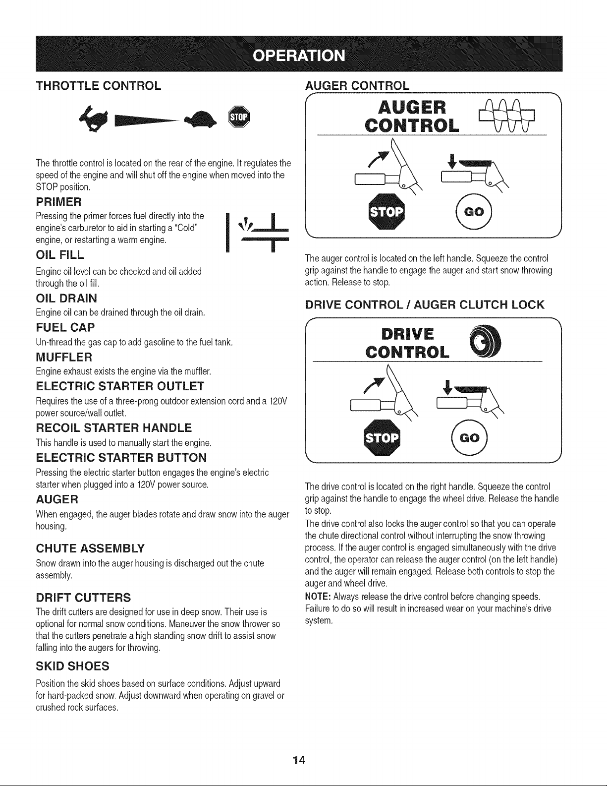
AUGER CONTROL
AUGER
CONTROL
&
J
Theaugercontrolis locatedon the lefthandle.Squeezethecontrol
gripagainstthehandletoengagetheaugerand startsnowthrowing
action.Releaseto stop.
DRIVE CONTROL / AUGER CLUTCH LOCK
Thedrivecontrolis locatedon therighthandle.Squeezethecontrol
gripagainstthehandletoengagethewheeldrive.Releasethehandle
to stop.
Thedrivecontrolalso lockstheaugercontrolsothatyoucanoperate
thechutedirectionalcontrolwithoutinterruptingthe snowthrowing
process.If theaugercontrolis engagedsimultaneouslywiththedrive
control,theoperatorcanreleasetheaugercontrol(onthelefthandle)
andtheaugerwill remainengaged.Releasebothcontrolsto stopthe
augerand wheeldrive.
NOTE:Alwaysreleasethedrivecontrolbeforechangingspeeds.
Failuretodoso will resultin increasedwearonyourmachine'sdrive
system.
SKiD SHOES
Positiontheskidshoesbasedon surfaceconditions.Adjustupward
forhard-packedsnow.Adjustdownwardwhenoperatingongravelor
crushedrocksurfaces.
14
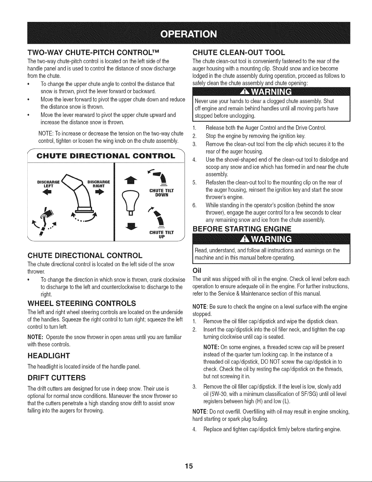
TWO-WAY CHUTE-PITCH CONTROLTM
Thetwo-waychute-pitchcontrolislocatedon theleftsideof the
handlepaneland isusedtocontrolthedistanceofsnowdischarge
fromthechute.
* Tochangetheupperchuteangletocontrolthedistancethat
snowisthrown,pivottheleverforwardor backward.
Movetheleverforwardto pivotthe upperchutedownandreduce
thedistancesnowisthrown.
Movetheleverrearwardtopivottheupperchuteupwardand
increasethedistancesnowisthrown.
NOTE:Toincreaseordecreasethe tensiononthetwo-waychute
control,tightenor loosenthewingknobonthechuteassembly.
CHUTE DiRECTiONAL CONTROL
DISCHARGE
LEFT
i
i
CHUTE TiLT
DOWN
V
,.b
!
.,j
CHUTE TiLT
UP
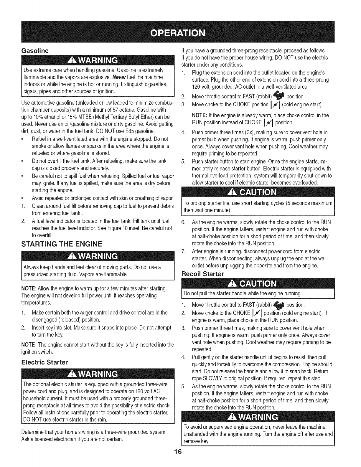
CHUTE CLEAN-OUT TOOL
Thechuteclean-outtoolisconvenientlyfastenedtotherearofthe
augerhousingwitha mountingclip.Shouldsnowand icebecome
lodgedinthechuteassemblyduringoperation,proceedasfollowsto
safelycleanthechuteassemblyandchuteopening:
Neveruseyourhandstocleara cloggedchuteassembly.Shut
off engineandremainbehindhandlesuntilall movingpartshave
stoppedbeforeunclogging.
1. ReleaseboththeAugerControlandtheDriveControl.
2. Stoptheenginebyremovingtheignitionkey.
3. Removetheclean-outtoolfromtheclip whichsecuresit tothe
rearoftheaugerhousing.
4. Usetheshovel-shapedendoftheclean-outtooltodislodgeand
scoopanysnowandicewhichhasformedinand nearthechute
assembly.
5. Refastentheclean-outtoolto themountingclipon therearof
theaugerhousing,reinserttheignitionkeyandstartthesnow
thrower'sengine.
6. Whilestandingintheoperator'sposition(behindthesnow
thrower),engagetheaugercontrolfora fewsecondstoclear
anyremainingsnowandicefromthechuteassembly.
BEFORE STARTING ENGINE
.J
CHUTE DIRECTIONAL CONTROL
Thechutedirectionalcontrolislocatedon theleftsideofthe snow
thrower.
* Tochangethedirectioninwhichsnowisthrown,crankclockwise
todischargetotheIdt and counterclockwisetodischargetothe
right.
WHEEL STEERING CONTROLS
Theleft andrightwheelsteeringcontrolsarelocatedon theunderside
ofthehandles.Squeezethe rightcontroltoturnright;squeezetheleft
controltoturnleft.
NOTE: Operatethesnowthrowerinopenareasuntilyou arefamiliar
withthesecontrols.
HEADLIGHT
Theheadlightislocatedinsideof the handlepanel.
DRIFT CUTTERS
Thedrift cuttersaredesignedforuse indeepsnow.Theiruseis
optionalfornormalsnowconditions.Maneuverthesnowthrowerso
thatthecutterspenetratea highstandingsnowdrifttoassistsnow
fallingintotheaugersforthrowing.
Read,understand,andfollowallinstructionsandwarningsonthe
machineandinthis manualbeforeoperating.
Oil
Theunitwas shippedwith oilin theengine.Checkoillevelbeforeeach
operationtoensureadequateoil intheengine.Forfurtherinstructions,
refertotheService&Maintenancesectionofthis manual.
NOTE:Besureto checktheengineona levelsurfacewiththeengine
stopped.
1. Removetheoilfillercap/dipstickandwipethedipstickclean.
2. Insertthecap/dipstickintotheoilfiller neck,andtightenthe cap
turningclockwiseuntilcap is seated.
NOTE:Onsomeengines,a threadedscrewcapwillbe present
insteadofthequarterturnlockingcap. Intheinstanceofa
threadedoilcap/dipstick,DONOTscrewthecap/dipstickin to
check.Checktheoil byrestingthecap/dipstickon thethreads,
butnot screwingitin.
Removethe oilfillercap/dipstick.Ifthe levelislow,slowlyadd
oil (5W-30,witha minimumclassificationofSF/SG)untiloil level
registersbetweenhigh(H)andlow(L).
NOTE:Donotoverfill.Overfillingwithoil mayresultin enginesmoking,
hardstartingor sparkplugfouling.
4. Replaceandtightencap/dipstickfirmlybeforestartingengine.
15
Gasoline
Useextremecarewhenhandlinggasoline.Gasolineisextremely
flammableandthevaporsareexplosive.Neverfuel themachine
indoorsorwhilethe engineis hot or running.Extinguishcigarettes,
cigars,pipesandothersourcesofignition.
Useautomotivegasoline(unleadedorlowleadedtominimizecombus-
tionchamberdeposits)witha minimumof87octane.Gasolinewith
upto 10%ethanolor 15%MTBE(MethylTertiaryButylEther)canbe
used.Neveruseanoil/gasolinemixtureordirtygasoline.Avoidgetting
dirt,dust,or waterin thefuel tank. DO NOTuse E85gasoline.
• Refuelin awell-ventilatedareawiththeenginestopped.Donot
smokeorallowflamesorsparksintheareawheretheengineis
refueledorwheregasolineisstored.
• Do notoverfillthefueltank.Afterrefueling,makesurethetank
capisclosedproperlyandsecurely.
• Becarefulnottospillfuel when refueling.Spilledfuelor fuelvapor
mayignite.Ifany fuel is spilled,makesurethe areaisdrybefore
startingtheengine.
• Avoidrepeatedorprolongedcontactwithskinor breathingofvapor
1. Cleanaroundfuelfill beforeremovingcaptofuelto preventdebris
fromenteringfueltank..
2. Afuel levelindicatorislocatedinthe fuel tank. Filltankuntilfuel
reachesthefuellevelindictor.SeeFigure10inset.Becarefulnot
tooverfill.
STARTING THE ENGINE
Alwayskeephandsandfeetclearofmovingparts.Do notusea
pressurizedstartingfluid.Vaporsareflammable.
Ifyouhaveagroundedthree-prongreceptacle,proceedasfollows.
Ifyoudonot havethe properhousewiring,DONOTusetheelectric
starterunderanyconditions.
1. Plugtheextensioncord intothe outletlocatedon the engine's
surface.Plugtheotherendof extensioncord intoa three-prong
120-volt,grounded,ACoutletina well-ventilatedarea.
2. Movethrottlecontrolto FAST(rabbit)_ position.
3. Movechoketothe CHOKEpositionI.,.,¢1(coldenginestart).
NOTE:Iftheengineis alreadywarm,placechokecontrolin the
RUNpositioninsteadofCHOKEI,,_¢I position.
4. Pushprimerthreetimes(3x),makingsureto coverventholein
primerbulbwhenpushing.Ifengineiswarm,pushprimeronly
once.Alwayscoverventholewhenpushing.Coolweathermay
requireprimingtobe repeated.
5. Pushstarterbuttonto startengine.Oncetheenginestarts,im-
mediatelyreleasestarterbutton.Electricstarterisequippedwith
thermaloverloadprotection;systemwilltemporarilyshut-downto
allowstartertocoolifelectricstarterbecomesoverloaded.
Toprolongstarterlife,useshortstartingcycles(5secondsmaximum
thenwaitone minute).
6. Astheenginewarms,slowlyrotatethechokecontroltotheRUN
position.Iftheenginefalters,restartengineandrunwith choke
at half-chokepositionfor a shortperiodoftime,andthenslowly
rotatethechokeintotheRUNposition.
7. Afterengineis running,disconnectpowercordfromelectric
starter.Whendisconnecting,alwaysunplugtheendat the wall
outletbeforeunpluggingtheoppositeendfromtheengine.
Recoil Starter
NOTE:Allowtheengineto warmupfor a fewminutesafterstarting.
Theenginewill not developfullpoweruntilit reachesoperating
temperatures.
1. Makecertainboththeaugercontrolanddrivecontrolare inthe
disengaged(released)position.
2. Insertkeyintoslot.Makesureit snapsinto place.Do notattempt
toturnthe key.
NOTE:The enginecannotstart withoutthekeyisfullyinsertedintothe
ignitionswitch.
Electric Starter
Theoptionalelectricstarterisequippedwitha groundedthree-wire
powercordandplug,andisdesignedtooperateon 120voltAC
householdcurrent.It mustbeusedwitha properlygroundedthree-
prongreceptacleatalltimesto avoidthepossibilityofelectricshock.
Followall instructionscarefullypriortooperatingtheelectricstarter.
DONOTuseelectricstarterin the rain.
Determinethatyourhome'swiringis a three-wiregroundedsystem.
Aska licensedelectricianifyouarenot certain.
Donot pullthestarterhandlewhiletheenginerunning.
1. Movethrottlecontrolto FAST(rabbit)_1 position.
2. Movechoketothe CHOKEI,,,¢1position_(coldenginestart).If
engineiswarm,placechokeinthe RUNposition.
3. Pushprimerthreetimes,makingsureto coverventholewhen
pushing.If engineis warm,pushprimeronlyonce.Alwayscover
ventholewhenpushing.Coolweathermayrequireprimingto be
repeated.
4. Pullgentlyonthestarterhandleuntilit beginsto resist,thenpull
quicklyandforcefullyto overcomethecompression.Engineshould
start.Donotreleasethe handleandallowittosnapback.Return
ropeSLOWLYtooriginalposition.Ifrequired,repeatthisstep.
5. Astheenginewarms,slowlyrotatethechokecontroltotheRUN
position.Iftheenginefalters,restartengineandrunwith choke
at half-chokepositionfor a shortperiodoftime,andthenslowly
rotatethechokeintotheRUNposition.
Toavoidunsupervisedengineoperation,neverleavethemachine
unattendedwiththeenginerunning.Turntheengineoff afteruseand
removekey.
16
STOPPING THE ENGINE
Afteryouhavefinishedsnow-throwing,runenginefor a fewminutes
beforestoppingto helpdryoff anymoistureon theengine.
1. Movethrottlecontrolto STOPi_ position.
DoNOTmovethechokecontroltoCHOKE IJl positiontostop
theengine.Backfireorenginedamagemayoccur.
2. Removethekey.Removingthekeywill reducethepossibilityof
unauthorizedstartingoftheenginewhileequipmentis notin use.
Keepthekeyina safeplace.Theenginecannotstartwithoutthe
key.
3. Wipeallsnowandmoisturefromtheareaaroundtheengineas
wellastheareainandaroundthewheeldrivecontrolandauger
control.Also,engageand releasebothcontrolsseveraltimes.
TO ENGAGE DRIVE
1. Withthe throttlecontrolin theFast(rabbit)_ position,move
speedselector leverintooneofthesix forward(F)positionsor
two reverse(R) positions.Selectaspeedappropriateforthe
snowconditionsanda paceyou'recomfortablewith.
NOTE: Whenselectinga DriveSpeed,usetheslowerspeeds
untilyouarecomfortableandfamiliarwiththeoperationofthe
snowthrower.
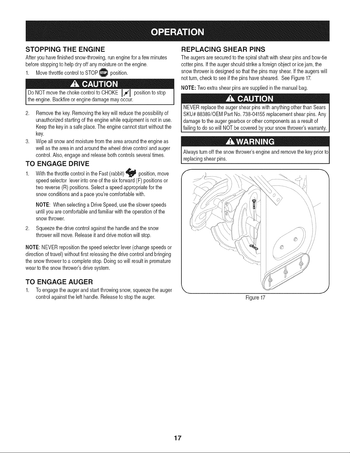
REPLACING SHEAR PiNS
Theaugersaresecuredtothespiralshaftwith shearpinsandbow-tie
cotterpins.Ifthe augershouldstrikeaforeignobjector icejam, the
snowthrowerisdesignedsothatthe pinsmayshear.Iftheaugerswill
notturn,checkto see if the pinshavesheared. SeeFigure17.
NOTE:Twoextrashearpinsaresuppliedin the manualbag.
NEVERreplacetheaugershearpinswithanythingotherthan Sears
SKU#88389/0EM PartNo.738-04155replacementshearpins.Any
damagetotheaugergearboxorothercomponentsasa resultof
failingto do sowill NOTbecoveredbyyour snowthrower'swarranty.
Alwaysturnoffthe snowthrower'sengineandremovethekeypriorto
replacingshearpins.
2. Squeezethedrivecontrolagainstthehandleandthesnow
throwerwillmove.Releaseitand drivemotionwillstop.
NOTE:NEVERrepositionthe speedselectorlever(changespeedsor
directionoftravel)withoutfirst releasingthedrivecontroland bringing
the snowthrowertoa completestop.Doingsowillresultin premature
weartothe snowthrower'sdrivesystem.
TO ENGAGE AUGER
1. Toengagetheaugerandstartthrowingsnow,squeezetheauger
controlagainsttheleft handle.Releasetostoptheauger.
\
Figure17
17
MAINTENANCE SCHEDULE
Beforeperforminganytypeof maintenance/service,disengageall
controlsandstoptheengine.Waituntilallmovingpartshavecometoa
completestop.Removethekeyto preventunintendedstarting.Always
wearsafetyglassesduringoperationorwhileperforminganyadjustments
orrepairs.
EachUse
1st5 - 8 hours
25 hours
50 hours
Annuallyor100hours
1. Engineoillevel
2. Looseormissinghardware
3. Unitandengine.
1. Engineoil
1. Engineoi11-
2. Controllinkagesand pivots
1. Engineoil
1. Sparkplug
1. Check
2. Tightenor replace
3. Clean
1. Change
1. Change
2. Lubewithlightoil
1. Change
1. Cleanand re-gap,orelse replace
withnewplug.
BeforeStorage 1. Fuelsystem
1. Runengineuntilit stopsfromlackof
fueloradda gasolineadditivetothe
gasin thetank.
Underheavyloador inhightemperatures
Followthemaintenanceschedulegivenbelow.Thischartdescribes
serviceguidelinesonly.UsetheServiceLogcolumnto keeptrackof
completedmaintenancetasks.Tolocate the nearestSearsService
Centeror toscheduleservice,simplycontactSearsat
1-800-4-MY-HOME®.
= =
ENGINE MAINTENANCE
Checking Engine Oil
Beforelubricating,repairing,or inspecting,disengageallcontrolsand
stopengine.Waituntilallmovingpartshavecometoa completestop.
Removethekeyto preventunintendedfiringofthe engine.
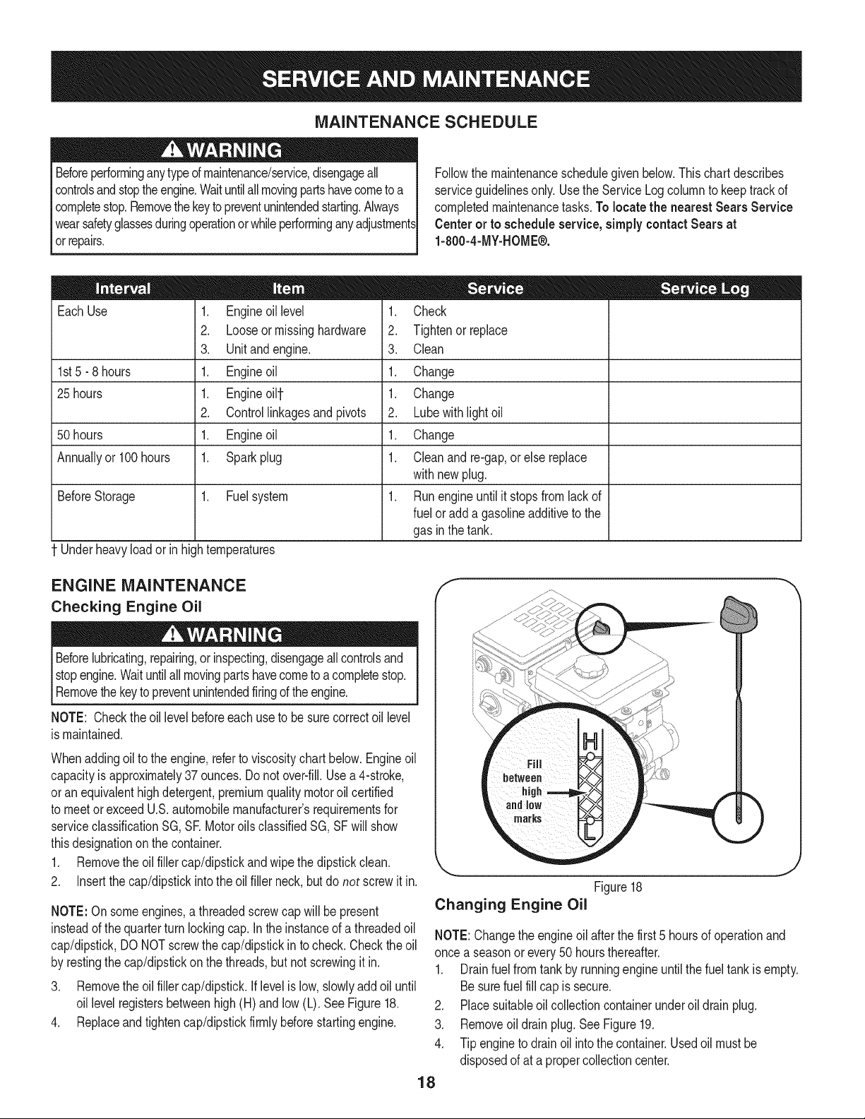
NOTE: Checktheoil levelbeforeeachuseto besurecorrectoil level
ismaintained.
Whenaddingoiltotheengine,referto viscositychart below.Engineoil
capacityisapproximately37 ounces.Donotover-fill.Usea4-stroke,
oran equivalenthighdetergent,premiumqualitymotoroilcertified
tomeetorexceedU.S.automobilemanufacturer'srequirementsfor
serviceclassificationSG, SR MotoroilsclassifiedSG,SFwillshow
thisdesignationonthe container.
1. Removetheoil fillercap/dipstickandwipethe dipstickclean.
2. Insertthe cap/dipstickintotheoil fillerneck,butdo not screwit in.
NOTE:On someengines,a threadedscrewcap will bepresent
insteadofthequarterturnlockingcap.In the instanceof a threadedoil
cap/dipstick,DONOTscrewthecap/dipstickin tocheck.Checkthe oil
byrestingthecap/dipstickonthethreads,butnot screwingitin.
3. Removetheoil fillercap/dipstick,iflevelislow,slowlyaddoiluntil
oil levelregistersbetweenhigh(H)andlow (L). SeeFigure18.
4. Replaceandtightencap/dipstickfirmlybeforestartingengine.
J
Figure18
Changing Engine Oil
NOTE:Changetheengineoil afterthefirst 5 hoursof operationand
oncea seasonorevery50 hoursthereafter.
1. Drainfuelfromtankbyrunningengineuntilthefueltankis empty.
Besurefuelfillcapis secure.
2. Placesuitableoil collectioncontainerunderoil drainplug.
3. Removeoil drainplug.SeeFigure19.
4. Tipenginetodrainoil intothe container.Usedoil mustbe
disposedofata propercollectioncenter.
18
f
Oil Drain
Plug
Figure19
Usedoil is a hazardouswasteproduct.Disposeof usedoil properly.
Donotdiscardwith householdwaste.Checkwithyourlocalauthori-
tiesor SearsServiceCenterforsafedisposal/recyclingfacilities.
iftheenginehasbeenrunning,themufflerwillbeveryhot.Becareful
nottotouchthemuffler.
NOTE: Checkthesparkplugonce a seasonor every25 hoursof
operation.Changethe sparkplugoncea seasonorevery100hours.
Toensureproperengineoperation,thesparkplugmustbeproperly
gappedandfreeofdeposits.
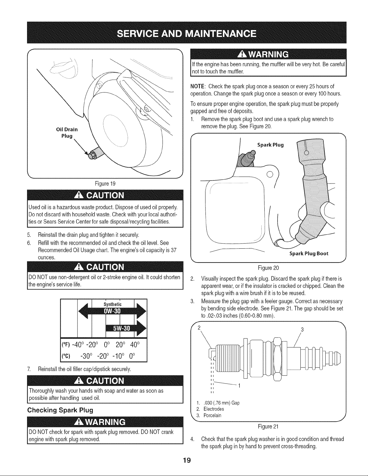
1. Removethesparkplugbootand usea sparkplugwrenchto
removetheplug.SeeFigure20.
Spark Plug
.
Reinstallthedrainplugandtightenit securely.
6.
Refillwiththerecommendedoil andchecktheoil level.See
RecommendedOil Usage chart. The engine's oil capacity is 37
ounces.
DONOTuse non-detergentoilor 2-strokeengineoil.Itcouldshorten
theengine'sservicelife.
(°F}=40o =20o 0o 200 400
(°c) -30° -20° -10° 0°
7. Reinstalltheoilfillercap/dipsticksecurely.
Thoroughlywashyourhandswithsoapandwaterassoonas
possibleafterhandling usedoil.
Checking Spark Plug
DONOTcheckfor sparkwithsparkplugremoved.DONOTcrank
enginewithsparkplugremoved.
Figure20
2. Visuallyinspectthe sparkplug. Discardthe sparkplugif thereis
apparentwear,oriftheinsulatoriscrackedorchipped.Cleanthe
sparkplugwithawirebrushif it is to be reused.
3. Measurethepluggapwitha feelergauge.Correctasnecessary
bybendingsideelectrode.SeeFigure21.Thegap shouldbe set
to .02-.03inches(0.60-0.80ram).
,'2 3
1..030 (.76 mm) Gap
2. Electrodes
k"_i Porcelain
Figure21
4. Checkthatthe sparkplugwasheris ingoodconditionandthread
thesparkpluginbyhandto preventcross-threading.
19
5. Afterthe sparkplugis seated,tightenwitha sparkplugwrenchto
compressthewasher.
NOTE:Wheninstallinga newsparkplug,tighten1/2-turnafterthe
sparkplugseatstocompressthewasher.Whenreinstallinga used
sparkplug,tighten1/8-to 1/4-turnafterthesparkplugseatsto
compressthewasher.
hotandcan ine.
CARBURETOR ADJUSTMENT
Thecarburetoris notuseradjustable.ContactSearsParts& Repairfor
adjustment.
LUBRICATION
Drive and Shifting Mechanism
Atleastoncea seasonorafterevery25 hoursofoperation,remove
rearcover.Lubricateallchains,sprockets,gears,bearings,shafts,and
theshiftingmechanism.Useengineoil ora spraylubricant.Referto
Figure22.
NOTE:Beforetippingtheunitonthe fronthousing,runthefueltank
emptyso fueldoesnotleakoutof thefuelcap.
1. Carefullypivotthesnowthrowerupandforwardsothat itrestson
theaugerhousing.
2. Removetheframecoverfromtheundersideofthe snowthrower
byremovingtheself-tappingscrewswhichsecureit. Referto
Figure27.
3. Applya lightcoatingof engineoil (or3-in-1oil) tothehexshaft.
SeeFig.22.
Wheels
At leastoncea season,removebothwheels.Cleanandcoatthe axles
witha multipurposeautomotivegreasebeforereinstallingwheels.
Chute Directional Control
Onceaseason,lubricatetheeyebolt bushingandthespiralwith3-in-1
oil.
Auger Shaft
At leastoncea season,oneat a time,removeallof theshearpins
fromthe augershaft.Spraylubricantinsidethehubofeachauger
spiralassemblyandaroundthespacersonthe augershaft.
Greasefittingscan alsobe foundateachendof the augershaft.
Lubricatewitha greasegunoncea season.SeeFigure23.
Gear Case
Theaugergearcaseis equippedwitha greasefitting.Lubricatewith
greaseoncea season(orderpartnumber737-0168).SeeFigure6-2.
NOTE:Torelievepressure,removethe ventplugbeforelubricatingthe
gearcase.See Figure23. Failuretodosocouldresultindamageto
thegearcaseseals.
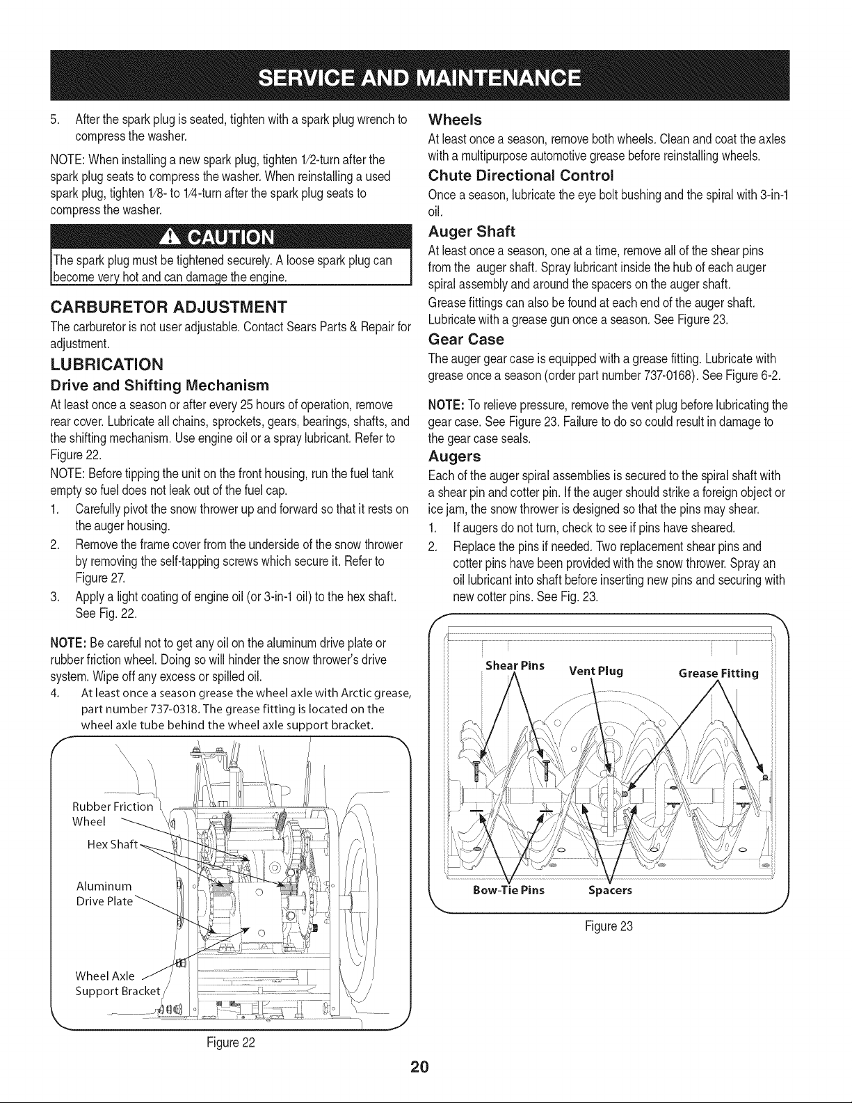
Augers
Eachoftheaugerspiralassembliesissecuredtothe spiralshaftwith
a shearpinandcotterpin.If theaugershouldstrikeaforeignobjector
icejam,thesnowthrowerisdesignedsothatthepinsmayshear.
1. Ifaugersdonot turn,checkto seeif pinshavesheared.
2. Replacethepinsif needed.Tworeplacementshearpinsand
cotterpins havebeenprovidedwiththesnowthrower.Sprayan
oil lubricantintoshaftbeforeinsertingnewpinsand securingwith
newcotter pins.See Fig.23.
NOTE:Becarefulnottogetanyoilon thealuminumdriveplateor
rubberfrictionwheel.Doingsowillhinderthesnowthrower'sdrive
system.Wipeoff anyexcessor spilledoil.
4. At least once a season grease the wheel axle with Arctic grease,
part number 737-0318. The grease fitting is located on the
wheel axle tube behind the wheel axle support bracket.
Rubber Friction
Wheel
Aluminum
Drive
Wheel Axle
Support Bracket
Figure22
Shear Pins Vent Plug Grease Fitting
2O
SHAVE PLATE AND SKiD SHOES
Theshaveplateand skidshoesonthebottomofthesnowthrowerare
subjectto wear.Theyshouldbecheckedperiodicallyandreplaced
whennecessary.
Skid Shoes
NOTE:Theskidshoesonthismachinehavetwowearedges.When
onesidewearsout, theycan be rotated1800to usethe otheredge.
1. Removethesix carriageboltsandhexnutsthatsecurethetwo
skidshoestothesidesof the augerhousing.Referto Figure24.
2. Positionthenewskidshoesandsecurewiththecarriagebolts
andhexnuts.Makecertaintheskidshoesare adjustedtobe
level.
Shave Plate
1. Removethehexnutsandcarriageboltsthatsecuretheshave
plateto the bottomofthehousing.Referto Figure24.
2. Removetherearmost hexnutand carriageboltsecuringtheback
ofeachskidshoeto the sidesofthehousing.Loosenthefour
remaininghexnutssecuringtheskidshoes.
3. Slidetheshaveplateoutoftheoff-setslotat thebottomofthe
housing,andfrombetweenthe skidshoesandsidepanelsofthe
housing.
4. Withthe mountingholestowardthebackoftheunit,slidethenew
shaveplateinto positionandsecurewiththefastenersremoved
previously.
f
k
J
Figure25
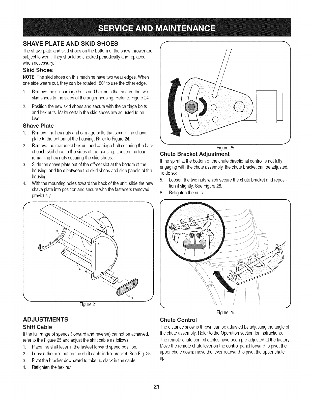
Chute Bracket Adjustment
Ifthespiralatthebottomof thechutedirectionalcontrolis notfully
engagingwiththechuteassembly,thechutebracketcanbeadjusted.
Todo so:
5. Loosenthetwo nutswhichsecurethechutebracketandreposi-
tionit slightly.SeeFigure26.
6. Retightenthenuts.
Figure24
ADJUSTMENTS
Shift Cable
If thefull rangeofspeeds(forwardandreverse)cannotbeachieved,
referto the Figure25 andadjusttheshiftcable as follows:
1. Placetheshiftleverin thefastestforwardspeedposition.
2. Loosenthehex nuton theshiftcable indexbracket.SeeFig.25.
3. Pivotthebracketdownwardto takeupslack inthecable.
4. Retightenthehexnut.
Figure26
Chute Control
Thedistancesnowis throwncanbe adjustedbyadjustingtheangleof
thechuteassembly.Refertothe Operationsectionforinstructions.
Theremotechutecontrolcableshavebeenpre-adjustedatthefactory.
Movethe remotechuteleveronthecontrolpanelforwardtopivotthe
upperchutedown;movetheleverrearwardtopivottheupperchute
up.
21
Wheel drive control
RefertotheAdjustmentsectionoftheAssemblyinstructionsto adjust
thewheeldrivecontrol.Tofurtherchecktheadjustment,proceedas
follows:
1. Withthe snowthrowertippedforward(becertainto runthe
fueltankdry beforetippingtheunitforward),removetheframe
coverunderneaththe snowthrowerby removingtheself-tapping
screws.SeeFig.27.
J
Figure27
Auger Control
RefertotheAssemblysectionforinstructionson adjustingtheauger
controlcable.
Skid Shoes
RefertotheAssemblysectionforinstructionson adjustingtheskid
shoes.
Tire Pressure
RefertotheAssemblysectionforinstructionson adjustingthetire
pressure.
BELT REPLACEMENT
Belt Removal Preparation
1. Removethechutecrankrodfromthechutecrankassemblyby
removingthehairpinclip shownin Fig.29.Movethechutecrank
rodawayfromtheassemblyas shown.
Removethreeself-tapscrewson bothsidesofthetransmission
housingas shownin Fig.29.
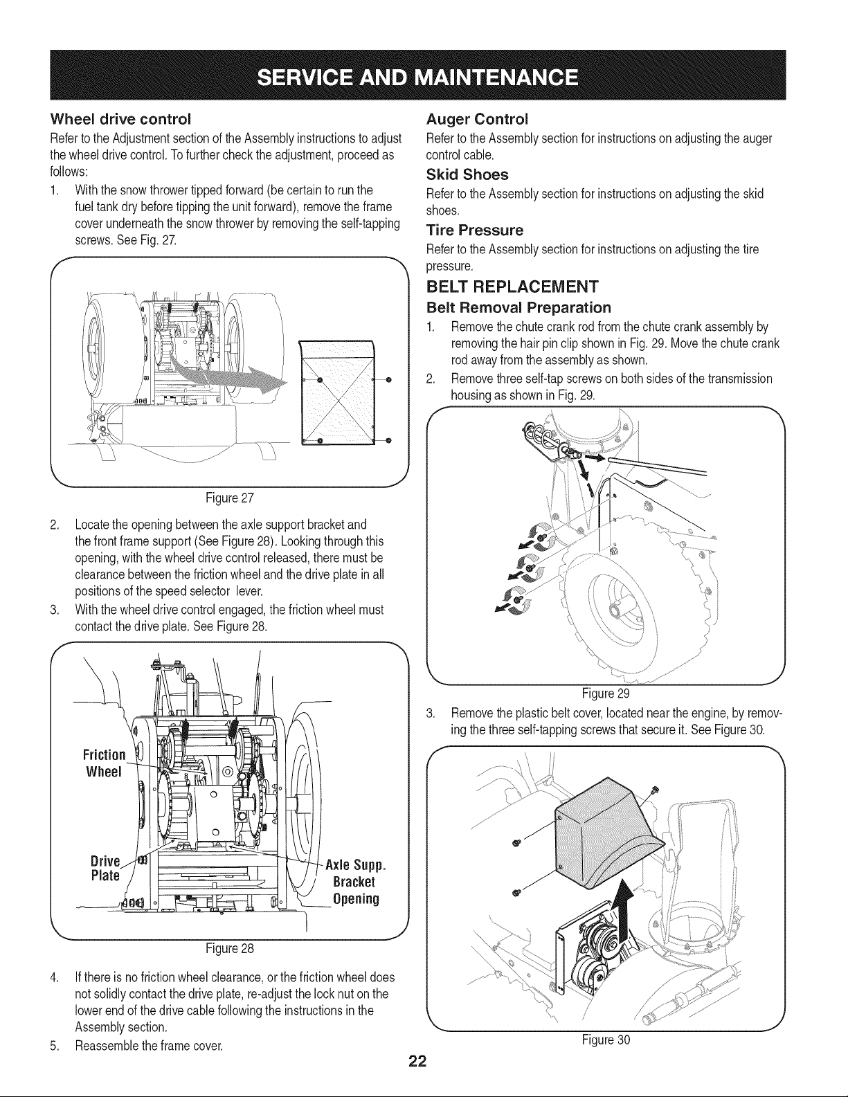
2. Locatetheopeningbetweentheaxlesupportbracketand
thefrontframesupport(SeeFigure28). Lookingthroughthis
opening,withthe wheeldrivecontrolreleased,theremustbe
clearancebetweenthefrictionwheelandthedriveplatein all
positionsofthespeedselectorlever.
3. Withthewheeldrivecontrolengaged,thefrictionwheelmust
contactthedrive plate.SeeFigure28.
Drive -Axle Supp.
Plate Bracket
Opening
Figure29
3. Removetheplasticbeltcover,locatednearthe engine,by remov-
ing thethreeself-tappingscrewsthatsecureit.See Figure30.
f
Figure28
4. Ifthere isnofrictionwheelclearance,orthefrictionwheeldoes
notsolidlycontactthedriveplate,re-adjustthelocknuton the
lowerendofthedrive cablefollowingtheinstructionsinthe
Assemblysection.
5. Reassembletheframecover.
22
 Loading...