

Craftsman 247888330 Owner’s Manual
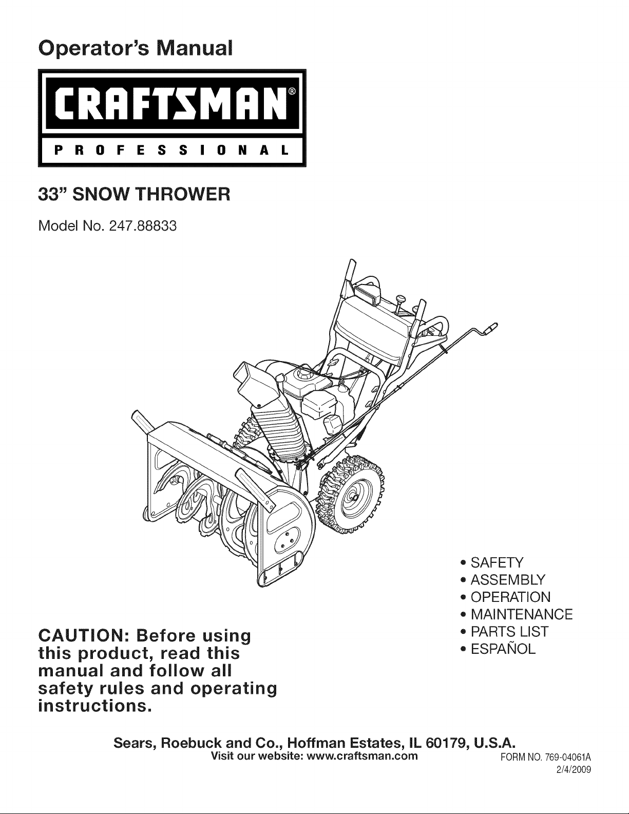
Operator's Manual
P R 0 F E S S I 0 N A L
33" SNOW THROWER
Model No. 247.88833
CAUTION: Before using
this product, read this
manual and follow all
safety rules and operating
instructions.
Sears, Roebuck and Co., Hoffman Estates, IL 60179, U.S.A.
Visit our website: www.craftsman.com FORMNO.769-04061A
, SAFETY
, ASSEMBLY
, OPERATION
, MAINTENANCE
, PARTS LIST
o ESPANOL
2/4/2009
WarrantyStatement..................................Page2
SafeOperationPractices..........................Pages3-6
SafetyLabels............................................Page7
Assembly..................................................Pages8-11
Operation..................................................Pages12-15
ServiceandMaintenance.........................Pages16-23
Off-SeasonStorage..................................Page24
Troubleshooting........................................Page25
PartsList...................................................Page26-41
RepairProtectionAgreement...................Page46
Espa_ol.....................................................Page47
ServiceNumbers......................................BackCover
CRAFTSMAN PROFESSIONALLiMiTED WARRANTY
Two Years on Snow Thrower
Whenoperatedand maintainedaccordingtoall suppliedinstructions,ifthis snowthrowerfailsdue toadefectin materialor workmanshipwithintwoyearsfrom
thedateorpurchase,call 1-800-4-MY-HOME®toarrangeforfreerepair.
Thiswarrantyappliesfor onlyone yearfromthe dateof purchaseif this snowthroweris everusedforcommercialorrentalpurposes.
Duringthefirst yearofpurchase,therewillbenochargefor warrantyservicein your home.Foryour convenience,in-homewarrantyservicewill stillbeavailable
afterthefirstyear of purchase,but atrip chargewill apply.Thischargewillbe waivedifyoutransportthe snowthrowerto anauthorizedCraftsmandrop-off
location.Forthe nearestauthorizedlocation,call1-800-4-MY-HOME®.
ThiswarrantycoversONLYdefectsinmaterialandworkmanship.SearswillNOTpayfor:
• Expendableitemsthatbecomewornduringnormaluse,includingbutnotlimitedto skidshoes,shaveplate,shearpins,sparkplug, air
cleaner,belts,and oilfilter.
• Standardmaintenanceservicing,oil changes,ortune-ups.
• Tirereplacementor repaircausedby puncturesfromoutsideobjects,suchasnails,thorns,stumps,or glass.
• Tireorwheelreplacementorrepairresultingfrom normalwear,accident,orimproperoperationormaintenance.
• Repairsnecessarybecauseofoperatorabuse,includingbut notlimitedto damagecausedby impactingobjectsthatbendthe frameor
crankshaft,orover-speedingtheengine.
• Repairsnecessarybecauseofoperatornegligence,includingbut notlimitedto,electricaland mechanicaldamagecausedbyimproper
storage,failureto usethe propergradeandamountofengineoil,orfailureto maintainthe equipmentaccordingtothe instructions
containedintheoperator'smanual.
• Engine(fuelsystem)cleaningor repairscausedbyfueldeterminedto becontaminatedor oxidized(stale).Ingeneral,fuelshouldbe
usedwithin30 daysof itspurchasedate.
• Normaldeteriorationandwearoftheexteriorfinishes,or productlabelreplacement.
Thiswarrantyappliesonly whilethisproductis withintheUnitedStates.
Thiswarrantygivesyouspecificlegalrights,andyoumayalsohaveother rightswhichvaryfromstateto state.
Sears, Roebuck andCo., Hoffman Estates,IL 60179
EngineOilType: SAE5W-30
EngineOilCapacity: 28ounces
FuelCapacity: 4 Quarts
SparkPlug: Champion®RC12YC
SparkPlugGap: .030"
©SearsBrands,LLC
Model Number.................................................................
Serial Number .................................................................
Dateof Purchase.............................................................
Recordthemodelnumber,serialnumber
anddateof purchaseabove
2
Thissymbolpointsoutimportantsafetyinstructionswhich,if not
followed,couldendangerthepersonalsafetyand/orpropertyof
yourselfandothers. Readandfollowallinstructionsin thismanual
beforeattemptingto operatethismachine.Failuretocomplywith
theseinstructionsmayresultinpersonalinjury.Whenyou seethis
symbol,HEEDITSWARNING!
Thismachinewasbuilttobeoperatedaccordingtothe safeopera-
tionpracticesinthismanual.Aswithanytypeof powerequipment,
carelessnessorerroronthe partoftheoperatorcanresultinserious
injury.Thismachineiscapableof amputatingfingers,hands,toes
andfeetandthrowingdebris.Failuretoobservethefollowingsafety
instructionscouldresultin seriousinjuryordeath.
CALIFORNIA PROPOSITION 65
EngineExhaust,someof itsconstituents,andcertainvehicle
componentscontainoremitchemicalsknowntoStateofCalifornia
tocausecancerandbirthdefectsorotherreproductiveharm,
TRAiNiNG
• Read,understand,andfollowall instructionsonthe machineand
in themanual(s)beforeattemptingtoassembleandoperate.
Failuretodosocan resultinseriousinjurytotheoperatorand/
orbystanders.Keepthismanualina safeplaceforfutureand
regularreferenceandfororderingreplacementparts. Forques-
tionscall,1-800-659-5917.
• Befamiliarwithallcontrolsandtheirproperoperation.Knowhow
tostopthemachineanddisengagethemquickly.
• Neverallowchildrenunder14yearsofagetooperatethis
machine.Children14andovershouldreadandunderstandthe
instructionsandsafeoperationpracticesinthismanualandon
themachineandbe trainedandsupervisedbyanadult.
• Neverallowadultstooperatethismachinewithoutproper
instruction.
• Thrownobjectscancauseseriouspersonalinjury.Planyour
snow-throwingpatterntoavoiddischargeof materialtoward
roads,bystandersandthelike.
• Keepbystanders,petsandchildrenat least75feetfromthe
machinewhileitisinoperation.Stopmachineifanyoneenters
thearea.
• Exercisecautiontoavoidslippingor falling,especiallywhen
operatinginreverse.
Your Responsibility--Restrict theuseofthis powermachineto
personswhoread,understandandfollowthewarningsandinstruc-
tionsinthismanualandon themachine,
SAVE THESE INSTRUCTIONS!
PREPARATION
Thoroughlyinspecttheareawheretheequipmentis to beused.
Removeall doormats,newspapers,sleds,boards,wiresandother
foreignobjects,whichcouldbetrippedoverorthrownbytheauger/
impeller.
Alwayswearsafetyglassesor eyeshieldsduringoperationand
whileperformingan adjustmentor repairto protectyoureyes.
Thrownobjectswhichricochetcancauseseriousinjurytothe
eyes.
Donot operatewithoutwearingadequatewinteroutergarments.
Donot wearjewelry,longscarvesorotherlooseclothing,which
couldbecomeentangledinmovingparts.Wearfootwearwhich
willimprovefootingonslipperysurfaces.
Usea groundedthree-wireextensioncordand receptacleforall
machineswithelectricstartengines.
Disengageall controlleversbeforestartingtheengine.
Adjustcollectorhousingheighttocleargravelorcrushedrock
surfaces.
Neverattempttomakeanyadjustmentswhileengineis running,
exceptwherespecificallyrecommendedinthe operator'smanual.
Letengineandmachineadjusttooutdoortemperaturebefore
startingtoclearsnow.
3
SafeHandlingof Gasoline
Toavoidpersonalinjuryorpropertydamageuseextremecarein
handlinggasoline.Gasolineisextremelyflammableandthevaporsare
explosive.Seriouspersonalinjurycanoccurwhengasolineisspilled
onyourselfor yourclotheswhichcanignite.Washyourskinand
changeclothesimmediately.
• Useonlyanapprovedgasolinecontainer.
• Extinguishall cigarettes,cigars,pipesandother sources
ofignition.
• Neverfuelmachineindoors.
• Neverremovegascaporaddfuelwhilethe engineishot
or running.
• Allowengineto coolat leasttwo minutesbeforerefueling.
• Neveroverfill fueltank.Filltanktono morethan1/2inch
belowbottomoffillerneckto providespaceforfuel
expansion.
• Replacegasolinecapandtightensecurely.
• Ifgasolineisspilled,wipeit offtheengineandequipment.
Movemachinetoanotherarea.Wait5 minutesbefore
startingtheengine.
• Neverstorethemachineor fuelcontainerinsidewhere
thereis anopenflame,sparkor pilotlight (e.g.furnace,
waterheater,spaceheater,clothesdryeretc.).
• Allowmachinetocoolatleast5 minutesbeforestoring.
• Neverfillcontainersinsidea vehicleor onatruckor trailer
bedwitha plasticliner.Alwaysplacecontainersonthe
groundawayfromyourvehiclebeforefilling.
• If possible,removegas-poweredequipmentfromthetruck
ortrailerand refuelit onthe ground.If thisisnotpossible,
thenrefuelsuchequipmentona trailerwitha portable
container,ratherthanfromagasolinedispensernozzle.
• Keepthenozzleincontactwiththe rimofthefueltankor
containeropeningatalltimesuntil fuelingiscomplete.Do
notuse a nozzlelock-opendevice.
OPERATION
• Do notputhandsorfeetnear rotatingparts,in theauger/impeller
housingorchuteassembly.Contactwiththerotatingpartscan
amputatehandsandfeet.
• Theauger/impellercontrolleverisa safetydevice.Neverbypass
itsoperation.Doingsomakesthemachineunsafeandmaycause
personalinjury.
• Thecontrolleversmustoperateeasilyinbothdirectionsand
automaticallyreturntothedisengagedpositionwhenreleased.
• Neveroperatewithamissingordamagedchuteassembly.Keep
all safetydevicesin placeandworking.
• Neverrunanengineindoorsor ina poorlyventilatedarea.Engine
exhaustcontainscarbonmonoxide,anodorlessanddeadlygas.
• Do notoperatemachinewhileunderthe influenceofalcoholor
drugs.
• Mufflerandenginebecomehotandcancauseaburn.Donot
touch.Keepchildrenaway.
• Exerciseextremecautionwhenoperatingon orcrossinggravel
surfaces.Stayalertforhiddenhazardsor traffic.
• Exercisecautionwhenchangingdirectionandwhileoperatingon
slopes.
• Planyoursnow-throwingpatternto avoiddischargetowards
windows,walls,carsetc. Thus,avoidingpossibleproperty
damageorpersonalinjurycausedbya ricochet.
• Neverdirectdischargeatchildren,bystandersand petsor allow
anyoneinfrontofthemachine.
• Donot overloadmachinecapacitybyattemptingtoclearsnowat
toofastof arate.
• Neveroperatethismachinewithoutgoodvisibilityorlight.Always
be sureofyourfootingand keepafirmholdonthehandles.Walk,
neverrun.
• Disengagepowerto theauger/impellerwhentransportingor not
in use.
• Neveroperatemachineat hightransportspeedsonslippery
surfaces.Lookdownand behindand usecare whenbackingup.
• Ifthemachineshouldstart tovibrateabnormally,stoptheengine,
disconnectthesparkplugwireandgrounditagainsttheengine.
Inspectthoroughlyfor damage.Repairanydamagebefore
startingandoperating.
• Disengageall controlleversandstopenginebeforeyouleave
theoperatingposition(behindthehandles).Waituntiltheauger/
impellercomestoa completestopbeforeuncloggingthechute
assembly,makingany adjustments,or inspections.
• Neverputyourhandinthedischargeorcollectoropenings.Do
notunclogchuteassemblywhileengineisrunning.Shutoff
engineand remainbehindhandlesuntilallmovingpartshave
stoppedbeforeunclogging.
• Useonlyattachmentsandaccessoriesapprovedbythemanufac-
turer(e.g.wheelweights,tirechains,cabsetc.).
• Whenstartingengine,pullcordslowlyuntilresistanceisfelt,then
pull rapidly.Rapidretractionofstartercord(kickback)willpull
handandarmtowardenginefasterthanyoucanletgo.Broken
bones,fractures,bruisesorsprainscouldresult.
• Ifsituationsoccurwhicharenotcoveredinthis manual,usecare
andgoodjudgment.ContactCustomerSupportforassistance
andthenameofyour nearestservicingdealer.
CLEARING A CLOGGED DISCHARGE CHUTE
Handcontactwiththe rotatingimpellerinsidethedischargechute
is themostcommoncauseofinjuryassociatedwithsnowthrowers.
Neveruseyourhandto cleanoutthedischargechute.
Toclear thechute:
1. SHUTTHEENGINEOFF!
2. Wait 10secondsto besuretheimpellerbladeshavestopped
rotating.
3. Alwaysuseaclean-outtool,not yourhands.
4
MAINTENANCE & STORAGE
• Nevertamperwithsafetydevices.Checktheirproperoperation
regularly.Refertothemaintenanceandadjustmentsectionsof
thismanual.
• Beforecleaning,repairing,or inspectingmachinedisengageall
controlleversandstopthe engine.Waituntiltheauger/impeller
cometoa completestop.Disconnectthe sparkplugwireand
groundagainsttheenginetopreventunintendedstarting.
Checkboltsand screwsfor propertightnessat frequentintervals
tokeepthe machineinsafeworkingcondition.Also,visually
inspectmachineforanydamage.
Donotchangetheenginegovernorsettingor over-speedthe
engine.Thegovernorcontrolsthe maximumsafeoperatingspeed
oftheengine.
Snowthrowershaveplatesandskidshoesaresubjecttowear
anddamage.Foryoursafetyprotection,frequentlycheckall
componentsand replacewithoriginalequipmentmanufacturer's
(OEM)partsonly."Useofpartswhichdonotmeettheoriginal
equipmentspecificationsmayleadto improperperformanceand
compromisesafety!"
Checkcontrolleversperiodicallytoverifytheyengageanddisen-
gageproperlyandadjust,if necessary.Refertotheadjustment
sectioninthisoperator'smanualforinstructions.
Maintainor replacesafetyandinstructionlabels,asnecessary.
• Observeproperdisposallawsand regulationsforgas,oil,etc. to
protecttheenvironment.
Priorto storing,runmachineafew minutestoclearsnowfrom
machineand preventfreezeupofauger/impeller.
Neverstorethemachineorfuelcontainerinsidewherethereisan
openflame,sparkorpilotlightsuchasa waterheater,furnace,
clothesdryeretc.
Alwaysrefertotheoperator'smanualforproperinstructionson
off-seasonstorage.
Checkfuelline,tank,cap,andfittingsfrequentlyforcracksor
leaks.Replaceif necessary.
Donotcrankenginewithsparkplugremoved.
AccordingtotheConsumerProductsSafetyCommission(CPSC)
andtheU.S.EnvironmentalProtectionAgency(EPA),thisproduct
hasan AverageUsefulLifeof seven(7)years,or 60hoursof
operation.AttheendoftheAverageUsefulLifehavethe machine
inspectedannuallybyanauthorizedservicedealertoensurethat
allmechanicalandsafetysystemsareworkingproperlyandnot
wornexcessively.Failuretodo socanresultinaccidents,injuries
ordeath.
DO NOT MODIFY ENGINE
Toavoidseriousinjuryor death,donot modifyengineinanyway.
Tamperingwiththegovernorsettingcanleadtoa runawayengineand
causeittooperateat unsafespeeds.Nevertamperwithfactorysetting
ofenginegovernor.
NOTICE REGARDING EMiSSiONS
EngineswhicharecertifiedtocomplywithCaliforniaandfederal
EPAemissionregulationsfor SORE(SmallOff RoadEquipment)are
certifiedto operateon regularunleadedgasoline,and mayinclude
thefollowingemissioncontrolsystems:EngineModification(EM),
OxidizingCatalyst(OC),SecondaryAirInjection(SAI)and ThreeWay
Catalyst(TWO)if soequipped.
SPARK ARRESTOR
Thismachineisequippedwithaninternalcombustionengineand
shouldnotbeusedonor nearanyunimprovedforest-covered,
brush-coveredorgrass-coveredlandunlesstheengine'sexhaust
systemisequippedwithasparkarrestermeetingapplicablelocalor
statelaws(ifany)
Ifasparkattesterisused,itshouldbemaintainedin effectiveworking
orderbytheoperator.IntheStateof Californiatheaboveis required
bylaw (Section4442ofthe CaliforniaPublicResourcesCode).Other
statesmayhavesimilarlaws. Federallawsapplyonfederallands.
A sparkarresterfor themuffleris availablethroughyournearestSears
PartsandRepairServiceCenter.
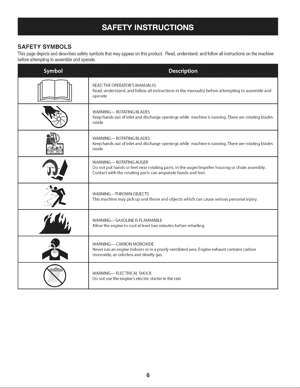
SAFETY SYMBOLS
Thispagedepictsanddescribessafetysymbolsthatmayappearonthisproduct. Read,understand,andfollowall instructionson themachine
beforeattemptingto assembleandoperate.
READ THE OPERATOR'S MANUAL(S)
i
i
Read, understand, and follow all instructions in the manual(s) before attempting to assemble and
operate
WARNING-- ROTATING BLADES
Keep hands out of inlet and discharge openings while machine is running. There are rotating blades
inside
WARNING-- ROTATING BLADES
Keep hands out of inlet and discharge openings while machine is running. There are rotating blades
inside
WARNING-- ROTATING AUGER
Do not put hands or feet near rotating parts, in the auger/impeller housing or chute assembly.
Contact with the rotating parts can amputate hands and feet.
WARNING--THROWN OBJECTS
This machine may pick up and throw and objects which can cause serious personal injury.
WARNING--GASOLINE IS FLAMMABLE
Allow the engine to cool at least two minutes before refueling.
WARNING-- CARBON MONOXIDE
Never run an engine indoors or in a poorly ventilated area. Engine exhaust contains carbon
monoxide, an odorless and deadly gas.
WARNING-- ELECTRICAL SHOCK
Do not use the engine's electric starter in the rain
6
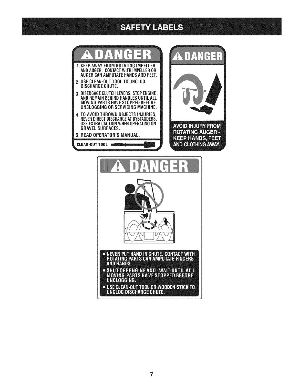
1.KEEPAWAYFROMROTATINGiMPELLER
ANDAUGER,CONTACTWiTHiMPELLEROR
AUGERCANAMPUTATEHANDSANDFEET.
2. USECLEAN-OUTTOOLTOUNCLOG
DISCHARGECHUTE.
3.DISENGAGECLUTCHLEVERS,STOPENGINE,
AND REMAINBEHINDHANDLESUNTILALL
MOVING PARTSHAVE STOPPEDBEFORE
UNCLOGGING OR SERViCiNGMACHINE.
TO AVOIDTHROWN OBJECTSiNJURiES,
NEVERDIRECTDISCHARGEATBYSTANDERS.
USEEXTRACAUTIONWHEN OPERATINGON
GRAVELSURFACES.
5.BEAD OPERATOR'S MANUAL.
CLEAN-OUT TOOL
7
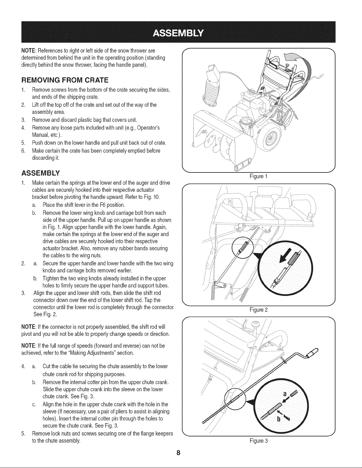
NOTE:Referencesto rightorleftsideofthesnowthrowerare
determinedfrombehindtheunitintheoperatingposition(standing
directlybehindthesnowthrower,facingthe handlepanel).
REMOVING FROM CRATE
1. Removescrewsfromthebottomof thecratesecuringthesides,
andendsoftheshippingcrate.
2. Liftoffthe topoffof the crateandsetoutof thewayofthe
assemblyarea.
3. Removeanddiscardplasticbagthatcoversunit.
4. Removeanyloosepartsincludedwithunit(e.g.,Operator's
Manual,etc.).
5. Pushdownonthelowerhandleandpullunitbackoutofcrate.
6. Makecertainthecratehasbeencompletelyemptiedbefore
discardingit.
ASSEMBLY
1. Makecertainthe springsat thelowerendoftheaugeranddrive
cablesaresecurelyhookedintotheirrespectiveactuator
bracketbeforepivotingthehandleupward.RefertoFig. 10.
a. Placethe shiftleverintheF6position.
b. Removethe lowerwingknobandcarriageboltfromeach
sideof the upperhandle.Pulluponupperhandleas shown
in Fig.1.Alignupperhandlewiththelowerhandle.Again,
makecertainthespringsatthelowerendof theaugerand
drivecablesaresecurelyhookedintotheir respective
actuatorbracket.Also,removeanyrubberbandssecuring
thecablestothewingnuts.
2. a. Securetheupperhandleandlowerhandlewiththetwo wing
knobsandcarriageboltsremovedearlier.
b. Tightenthetwo wingknobsalreadyinstalledin the upper
holesto firmlysecuretheupperhandleand supporttubes.
3. Aligntheupperand lowershiftrods,thenslidetheshift rod
connectordownoverthe endofthe lowershiftrod.Tapthe
connectoruntilthelowerrodiscompletelythroughtheconnector.
See Fig.2.
NOTE:If theconnectoris notproperlyassembled,the shift rodwill
pivotand youwillnotbe abletoproperlychangespeedsordirection.
Figure 1
/
Figure2
f
NOTE:If thefull rangeof speeds(forwardandreverse)can notbe
achieved,refertothe"MakingAdjustments"section.
4. a. Cutthecabletie securingthechuteassemblytothelower
chutecrankrodfor shippingpurposes.
b. Removethe internalcotterpinfromtheupperchutecrank.
Slidetheupperchutecrankintothesleeveon thelower
chutecrank.See Fig.3.
c. Alignthe holeinthe upperchutecrankwiththeholeinthe
sleeve(ifnecessary,useapairof plierstoassistinaligning
holes).Inserttheinternalcotterpinthroughtheholesto
securethechutecrank.SeeFig.3.
5. Removelocknutsand screwssecuringoneoftheflangekeepers
tothechuteassembly.
Figure3
8
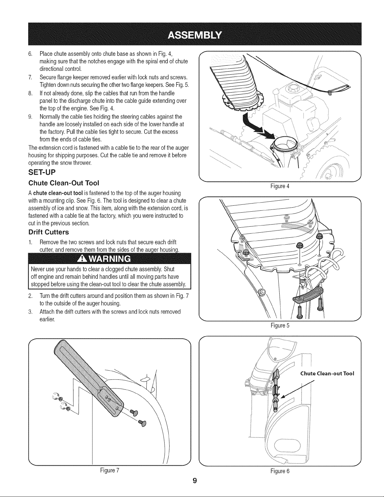
6. PlacechuteassemblyontochutebaseasshowninFig.4,
makingsurethatthenotchesengagewiththespiralendofchute
directionalcontrol.
7. Secureflangekeeperremovedearlierwithlocknutsandscrews.
Tightendownnutssecuringtheothertwoflangekeepers.SeeFig.5.
8. If notalreadydone,slipthe cablesthat runfromthehandle
paneltothedischargechuteintothecableguideextendingover
thetopof theengine.SeeFig.4.
9. Normallythecabletiesholdingthesteeringcablesagainstthe
handlearelooselyinstalledoneach sideofthe lowerhandleat
thefactory.Pullthecableties tighttosecure.Cuttheexcess
fromtheendsof cableties.
Theextensioncordisfastenedwithacabletieto therearoftheauger
housingforshippingpurposes.Cutthecabletie andremoveit before
operatingthesnowthrower.
SET-UP
Chute Clean=Out Tool
A chuteclean-outtool isfastenedtothetopoftheaugerhousing
withamountingclip.SeeFig.6.Thetoolisdesignedtoclearachute
assemblyofice andsnow.Thisitem,alongwiththe extensioncord,is
fastenedwithacabletieat the factory,whichyou wereinstructedto
cutintheprevioussection.
Drift Cutters
1. Removethetwo screwsand locknutsthatsecureeach drift
?
J
Figure4
Neveruseyour handstocleara cloggedchuteassembly.Shut
offengineandremainbehindhandlesuntilallmovingpartshave
stoppedbeforeusingtheclean-outtoolto clearthechuteassembly.
2. Turnthedriftcuttersaroundandpositionthemas shownin Fig.7
totheoutsideofthe augerhousing.
3. Attachthedriftcutterswiththescrewsand locknutsremoved
earlier.
F-
J
Figure5
f
Chute Clean=out Tool
Figure7
J
Figure6
9
Tire Pressure f
Beforeoperating,checktirepressure.Refertothetiresidewallfor
exacttire manufacturer'srecommendedor maximumpsi.
NOTE:Ifthetirepressureisnotequalinbothtires,theunitmaynot
travelina straightpathandtheshaveplatemaywearunevenly.
ADJUSTMENTS
Skid Shoes
Thesnowthrowerskidshoesareadjustedupwardatthefactoryfor
shippingpurposes.Adjustthemdownward,ifdesired,priortooperat-
ingthesnowthrower.
• Forclosesnowremovalona smoothsurface,raiseskidshoes
higherontheaugerhousing.
It is notrecommendedthatyouoperatethissnowthrowerongravel
asitcan easilypickupandthrowloosegravel,causingpersonal
injuryor damagetothesnowthrowerandsurroundingproperty.
Usea middleorlowerpositionwhentheareatobeclearedis
uneven.
NOTE:Ifyouchooseto operatethe snowthrowerona gravelsurface,
keeptheskidshoesin positionformaximumclearancebetweenthe
groundandtheshaveplate.
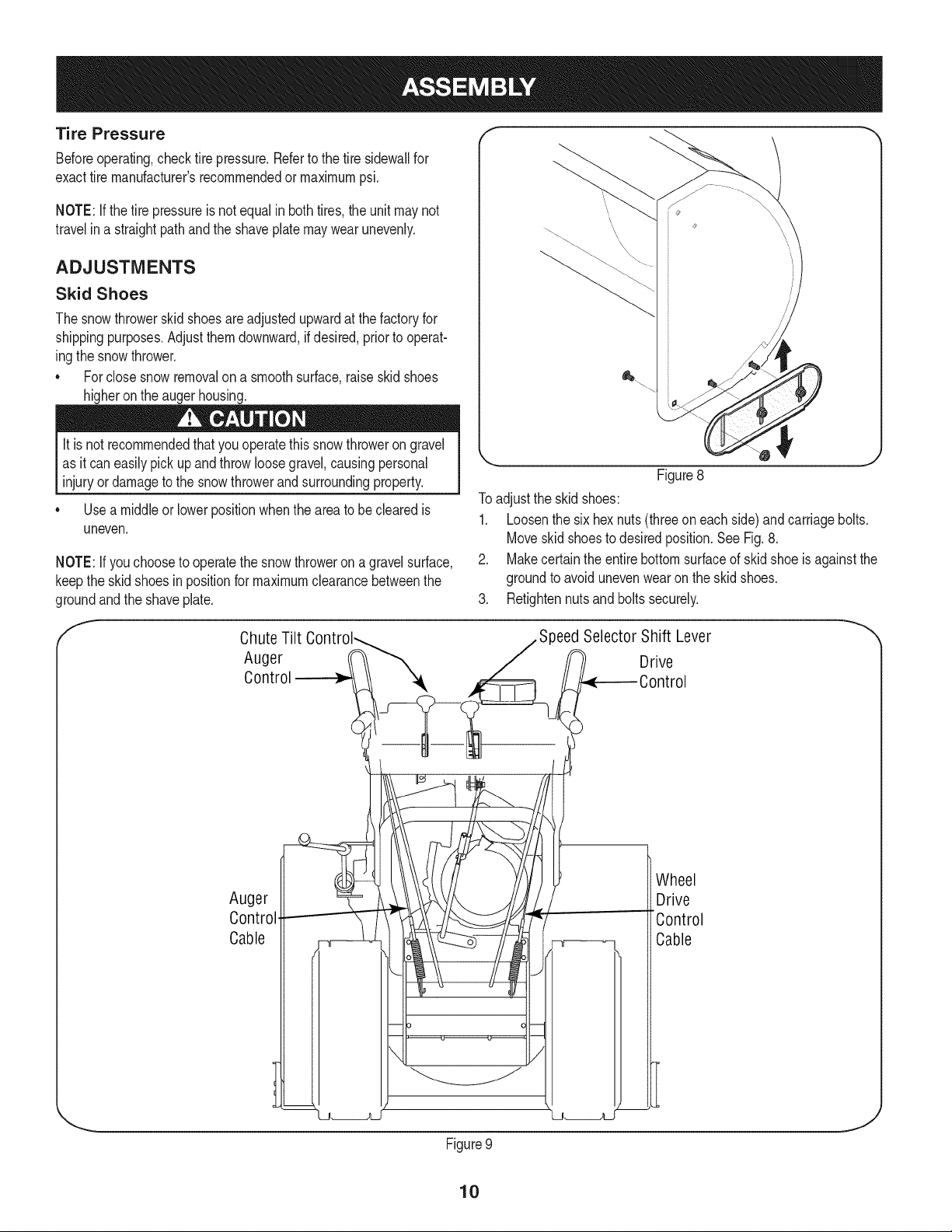
Figure8
Toadjusttheskidshoes:
1. Loosenthesixhexnuts(threeon eachside)andcarriagebolts.
Moveskidshoestodesiredposition.SeeFig.8.
2. Makecertaintheentirebottomsurfaceofskidshoe isagainstthe
groundtoavoidunevenwearon theskidshoes.
3. Retightennutsandboltssecurely.
f
Chute Tilt
Auger
Auger
Control
Cable
)eed Selector Shift Lever _'
Drive
Wheel
Drive
"Control
Cable
Figure9
10
J
Testing Auger Drive Control
Whentheaugercontrolis releasedandin the disengaged"up"posi-
tion,thecableshouldhaveverylittleslack,but shouldNOTbetight.
Referto Fig.9 forlocationofcontrols.
Priortooperatingyoursnowthrower,carefullyreadandfollowall
instructionsbelow.Performall adjustmentstoverifyyoursnow
throwerisoperatingsafelyandproperly.
1. Ina well-ventilatedarea,start thesnowthrowerengineas
instructedin theOperationsection.
2. Whilestandingintheoperator'sposition(behindthe snow
thrower),engagethe augercontrolandallowtheaugerto remain
engagedforapproximatelytensecondsbeforereleasingthe
augercontrol.Repeatthisseveraltimes.
3. Withtheenginerunningandtheaugercontrolinthedisengaged
"up"position,walktothefrontofthemachine.Confirmthatthe
augerhascompletelystoppedrotatingandshowsnosignsof
motion.
4. If theaugershowsanysignsof rotating,immediatelyreturntothe
operator'spositionandshutoff theengine.Waitfor allmoving
partstostopbeforereadjustingtheaugercontrolcable.
Testing Wheel Drive Control & Speed Selector
Shift Lever
Referto Fig.9 forlocationofcontrols.
1. Movetheshift leverintosixth(6) position.
2. Withthewheeldrivecontrolreleased,pushthesnowthrower
forward,thenpullit back.Themachineshouldmovefreely.
3. Engagethedrivecontrolandattempttomovethe machineboth
forwardandback,resistanceshouldbefelt.
4. Movetheshiftleverintothefastreverse(R2)positionand repeat
theprevioustwosteps.
If youexperiencedresistancerollingtheunit,either whenrepositioning
theshiftleverfrom6toR2orwhenattemptingtomovethemachine
withthedrivecontrolreleased,adjustthe drivecontrolimmediately.
SeeAdjustingDriveandAugerControls.
Adjusting Wheel Drive & Auger Controls
1. Frombeneaththehandle,pulldownwardontheappropriatecable
andunhookthespringfoundontheendofthecablefromits
respectiveactuatorbracket.RefertoFig.9and10.
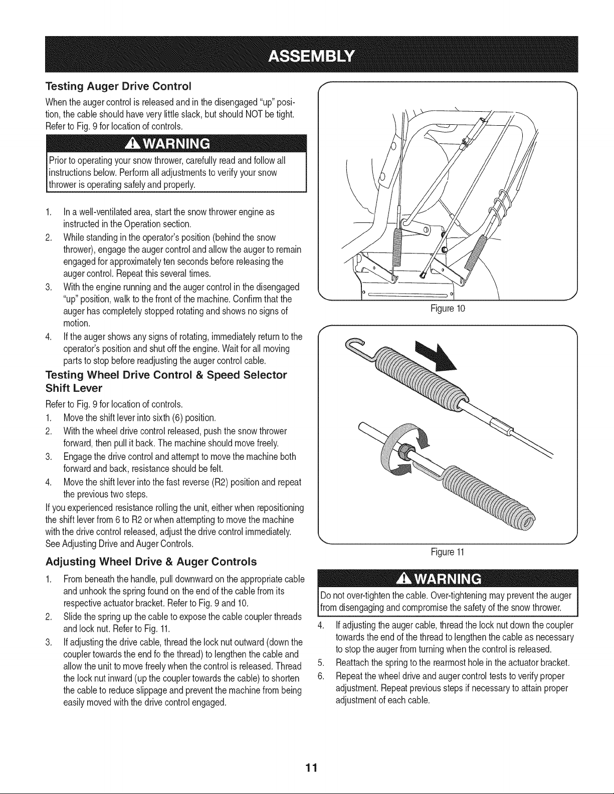
2. Slidethespringupthecableto exposethecablecouplerthreads
andlocknut. Referto Fig.11.
3. If adjustingthedrivecable,threadthelocknutoutward(downthe
couplertowardstheendfothethread)to lengthenthecableand
allowthe unittomovefreelywhenthecontrolis released.Thread
thelocknutinward(upthecouplertowardsthecable)toshorten
thecableto reduceslippageand preventthemachinefrombeing
easilymovedwiththedrivecontrolengaged.
_o
Figure10
J
Figure11
Donotover-tightenthecable.Over-tighteningmaypreventtheauger
fromdisengagingandcompromisethesafetyofthesnowthrower.
4. Ifadjustingtheaugercable,threadthe locknutdownthecoupler
towardstheendof thethreadto lengthenthecable asnecessary
to stoptheaugerfromturningwhenthecontrolisreleased.
5. Reattachthe springtothe rearmostholeintheactuatorbracket.
6. Repeatthe wheeldriveandaugercontrolteststoverifyproper
adjustment.Repeatpreviousstepsifnecessarytoattainproper
adjustmentofeachcable.
11
f
Headlk
GasCa
Drift
Cutters
Chute
Assembl
WheelDriveControl
SpeedSelector
_......_Shift LeverTwo-Way
WheelSteering
Control
ChuteDirectional
Control
Primer
Ignition
Key
ChuteControlTM
erControl
Muffler
On/ Off Switch
OilFill
Angers
SkidShoe
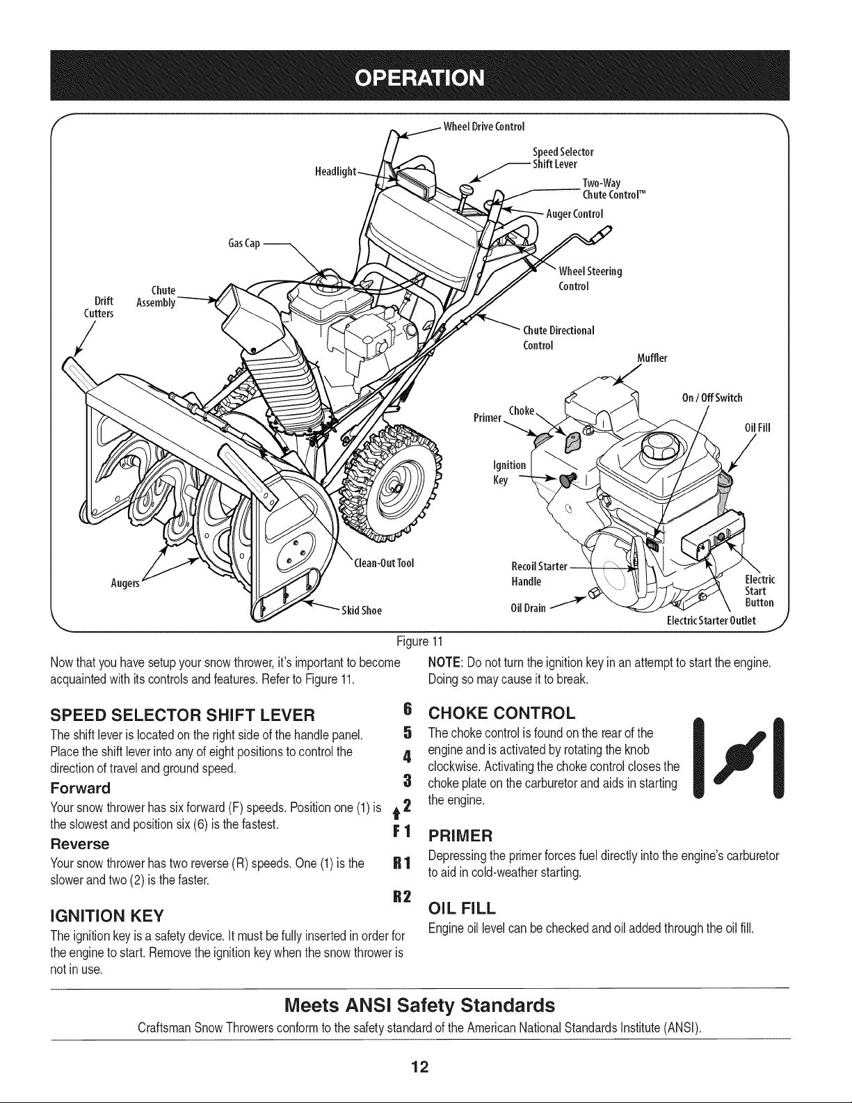
Figure11
Nowthat youhavesetupyoursnowthrower,it's importanttobecome
acquaintedwith itscontrolsandfeatures.RefertoFigure11.
SPEED SELECTOR SHIFT LEVER
Theshiftleverislocatedonthe rightsideofthehandlepanel.
Placethe shiftleverintoanyofeightpositionstocontrolthe
directionoftravelandgroundspeed.
Forward
Yoursnowthrowerhassixforward(F)speeds.Positionone(1)is t 2
theslowestand positionsix (6) isthefastest. F 1
Reverse
Yoursnowthrowerhastwo reverse(R) speeds.One(1)isthe
slowerandtwo(2) isthe faster.
IGNITION KEY
Theignitionkeyis asafetydevice.Itmustbefullyinsertedinorderfor
theenginetostart.Removethe ignitionkeywhenthesnowthroweris
notinuse.
Handle Electric
OilDrain -'_( Button
ElectricStarterOutlet
NOTE:Donot turntheignitionkeyinan attemptto starttheengine.
Doingsomaycauseit to break.
6 CHOKE CONTROL
5 Thechokecontrolis foundonthe rearof the
4 engineand isactivatedbyrotatingthe knob
clockwise.Activatingthechokecontrolclosesthe
3 chokeplateonthecarburetorandaidsinstarting
theengine.
PRIMER
Depressingthe primerforcesfueldirectlyintotheengine'scarburetor
toaid incold-weatherstarting.
OIL FILL
Engineoil levelcan becheckedandoiladdedthroughtheoilfill.
Start
J
Meets ANSI Safety Standards
CraftsmanSnowThrowersconformtothesafetystandardof theAmericanNationalStandardsInstitute(ANSI).
12
ON / OFF SWITCH
PressintotheON positionwhenstartingtheengineand willshutoff
theenginewhenmovedintotheOFFposition.
RECOIL STARTER HANDLE
Thishandleisusedto manuallystarttheengine.
ELECTRIC STARTER BUTTON
Pressingtheelectricstarterbuttonengagestheengine'selectric
starterwhenpluggedintoa 120Vpowersource.
f
ELECTRIC STARTER OUTLET
Requirestheuseof athree-prongoutdoorextensioncord(included)
anda120Vpowersource/walloutlet.
AUGERS
Whenengaged,theaugersrotateanddrawsnowintotheauger
housing.
CHUTE ASSEMBLY
Snowdrawnintotheaugerhousingisdischargedoutthechute
assembly.
GAS CAP
Unthreadthegascaptoaddgasolinetothe fuel tank.
AUGER CONTROL
S
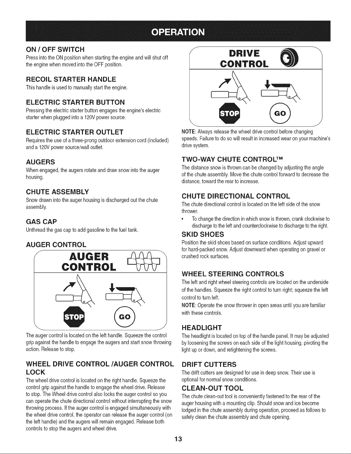
NOTE:Alwaysreleasethewheeldrivecontrolbeforechanging
speeds.Failuretodo sowill resultinincreasedwearonyourmachine's
drivesystem.
TWO-WAY CHUTE CONTROL TM
Thedistancesnowis throwncanbe changedbyadjustingthe angle
ofthechuteassembly.Movethe chutecontrolforwardto decreasethe
distance,towardthe rearto increase.
CHUTE DIRECTIONAL CONTROL
Thechutedirectionalcontrolislocatedontheleftsideofthesnow
thrower.
• Tochangethedirectioninwhichsnowisthrown,crankclockwiseto
dischargetotheleftandcounterclockwisetodischargeto theright.
SKID SHOES
Positiontheskidshoesbasedonsurfaceconditions.Adjustupward
forhard-packedsnow.Adjustdownwardwhenoperatingon gravelor
crushedrocksurfaces.
WHEEL STEERING CONTROLS
Theleftandrightwheelsteeringcontrolsarelocatedontheunderside
ofthehandles.Squeezethe rightcontroltoturnright;squeezethe left
controlto turnleft.
NOTE:Operatethesnowthrowerin openareasuntil youarefamiliar
withthesecontrols.
J
Theaugercontrolislocatedontheleft handle.Squeezethecontrol
gripagainstthehandletoengagetheaugersandstart snowthrowing
action.Releasetostop.
WHEEL DRIVE CONTROL/AUGER CONTROL
LOCK
Thewheeldrivecontrolislocatedon therighthandle.Squeezethe
controlgripagainstthehandletoengagethewheeldrive.Release
tostop.TheWheeldrivecontrolalsolockstheaugercontrolsoyou
canoperatethechutedirectionalcontrolwithoutinterruptingthe snow
throwingprocess.If theaugercontrolisengagedsimultaneouslywith
thewheeldrivecontrol,the operatorcan releasetheaugercontrol(on
thelefthandle)andtheaugerswill remainengaged.Releaseboth
controlstostopthe augersandwheeldrive.
HEADLIGHT
Theheadlightislocatedontopofthehandlepanel.It maybe adjusted
bylooseningthescrewsoneachsideof the lighthousing,pivotingthe
lightupor down,andretighteningthe screws.
DRIFT CUTTERS
Thedriftcuttersaredesignedforuseindeepsnow.Theiruseis
optionalfor normalsnowconditions.
CLEAN-OUT TOOL
Thechuteclean-outtoolisconvenientlyfastenedtotherearofthe
augerhousingwitha mountingclip.Shouldsnowandicebecome
lodgedinthechuteassemblyduringoperation,proceedasfollowsto
safelycleanthechuteassemblyandchuteopening.
13
CLEAN-OUT TOOL
Neveruseyourhandstoclearacloggedchuteassembly.Shut
off engineand remainbehindhandlesuntil allmovingpartshave
stoppedbeforeunclogging.
Thechuteclean-outtoolis convenientlyfastenedto the rearofthe
augerhousingwitha mountingclip. Shouldsnowandicebecome
lodgedin thechuteassemblyduringoperation,proceedasfollowsto
safelycleanthechuteassemblyandchuteopening:
1. Releaseboththe AugerControlandtheWheeldrivecontrol.
2. Stopthe enginebyremovingtheignitionkey.
3. Removetheclean-outtoolfromtheclipwhichsecuresittothe
rearoftheaugerhousing.
4. Usetheshovel-shapedendof theclean-outtooltodislodgeand
scoopanysnowand icewhichhasformedin andnearthechute
assembly.
5. Refastentheclean-outtooltothemountingclipontherearof
theaugerhousing,reinserttheignitionkeyandstartthesnow
thrower'sengine.
6. Whilestandingintheoperator'sposition(behindthesnow
thrower),engagethe augercontrolforafewsecondsto clearany
remainingsnowandice fromthechuteassembly.
BEFORE STARTING ENGINE
Read,understand,andfollowall instructionsandwarningson the
machineand inthismanualbeforeoperating.
Oil
Theunitwasshippedwithoilintheengine.Checkoil levelbeforeeach
operationto ensureadequateoilintheengine.Forfurtherinstructions,
referto the Service&Maintenancesectionof thismanual.
1. Removethedipstickfromtheoilfill.
2. Checkandmakesurethatthe levelofoil is uptothe FULLmark
onthedipstick.
3. Iftheoil levelisnotupto FULL,pourfreshmotoroil (5W-30,with
a minimumclassificationofSF/SG/SH/SJ)slowlythroughthe
opening.Replaceoil filldipstickandcheckoil levelagain.
Gasoline
• Storegasolineinaclean,approvedcontainerandkeepthecap in
placeonthecontainer.
• Makesurethatthecontainerfromwhichyoupourthegasolineis
cleanandfreefromrustor otherforeignparticles.
• Alwaysfillthefueltankoutdoorsand usea funnelorspoutto
preventspilling.
• Fillfuel tankwithclean,fresh,unleadedgasolinewithaminimum
of85 octane.Freshfuel preventsgumfromforminginthefuel
systemoronessentialcarburetorparts.Purchasefuelin a
quantitythatcanbeusedwithin30 days.
• Neverfillthe fuel tankcompletely.Fillthe tanktowithin1-1/2"
fromthetoptoprovidespaceforexpansionoffuel.
• Makesureto wipeoffanyspilledfuelbeforestartingtheengine.
STARTING THE ENGINE
1. Makecertainboththe augercontrolandwheeldrivecontrolarein
thedisengaged(released)position.
2. Insertignitionkeyintoslot.Makesureit snapsintoplace.Donot
attempttoturnthekey.
NOTE:Theenginecannotstartwithoutthekeyisfully insertedintothe
ignitionswitch.
Electric Starter
Determinethatyourhome'swiringis a three-wiregroundedsystem.
Askalicensedelectricianifyouarenotcertain.
Theoptionalelectricstarteris equippedwithagroundedthree-wire
powercordandplug,andis designedto operateon 120voltAC
householdcurrent.It mustbeusedwitha properlygroundedthree-
prongreceptacleatall timesto avoidthepossibilityofelectricshock.
Followall instructionscarefullypriortooperatingtheelectricstarter.
Ifyouhavea groundedthree-prongreceptacle,proceedasfollows:
1. Plugtheextensioncordintotheoutletlocatedontheengine's
surface.Plugtheotherendof extensioncordintoathree-prong
120-volt,grounded,ACoutletinawell-ventilatedarea.
2. Rotatechokecontrolto FULL I,,q¢lchokeposition(fora cold
enginestart).
NOTE:Iftheengineisalreadywarm,placechokecontrolin theOFF
I _ I positioninsteadof FULLIJl'
3. Depressprimer.If it is 15°For higherpushprimertwotimes,if
below15°F,pushprimerfour times.
4. PushrockerswitchtoONposition.
5. Pushstarterbuttonto startengine.
Toprolongstarterlife,use shortstartingcycles(5secondsmaximum
thenwaitone minute).
Useextremecarewhenhandlinggasoline.Gasolineisextremely
flammableandthevaporsareexplosive.Neverfuel themachine
indoorsorwhilethe engineishotor running.Extinguishcigarettes,
cigars,pipesandothersourcesof ignition.
NOTE:A plasticdustcap maybefoundinsidethefuelfillopening.
Removeanddiscard,if present.
6. Oncetheenginestarts,releasestarterbutton.
7. Allowtheenginetowarmupseveralminutes,adjustingchoke
towardRUNposition.Waituntilenginerunssmoothlybeforeeach
chokeadjustment.
8. Whendisconnectingthe extensioncord,alwaysunplugtheend
atthethree-prongwalloutletbeforeunpluggingtheoppositeend
fromthesnowthrower.
14
Recoil Starter
1. RotatechokecontroltoCHOKE Ill position.
2. Depressprimer.Ifit is 15°For higherpushprimertwotimes,if
below15°F,pushprimerfourtimes.
3. Pushrockerswitchto ONposition.
4. Graspthe recoilstarterhandleand slowlypullthe ropeout.At
thepointwhereitbecomesslightlyhardertopulltherope,slowly
allowthe ropeto recoil.
5. Pullthestarterhandlewitha firm,rapidstroke.Donot release
thehandleandallowitto snap back.Keepa firmholdonthe
starterhandleandallowit toslowlyrecoil.
6. Allowtheenginetowarmupseveralminutes,adjustingchoke
towardRUNposition.Waituntilenginerunssmoothlybeforeeach
chokeadjustment.
STOPPING THE ENGINE
Runenginefor a fewminutesbeforestoppingtohelpdryoff any
moistureonthe engine.
1. PushtheOn/ Offswitchto theOFFposition.
DoNOTmovethechokecontrolto CHOKE IJl positionto stop
theengine.Backfireor enginedamagemayoccur.
.
Removetheignitionkeyandstoreina safeplace.
3.
Wipeall snowandmoisturefromtheareaaroundtheengineas
wellas the areainandaroundthewheeldrivecontrolandauger
control.Also,engageandreleasebothcontrolsseveraltimes.
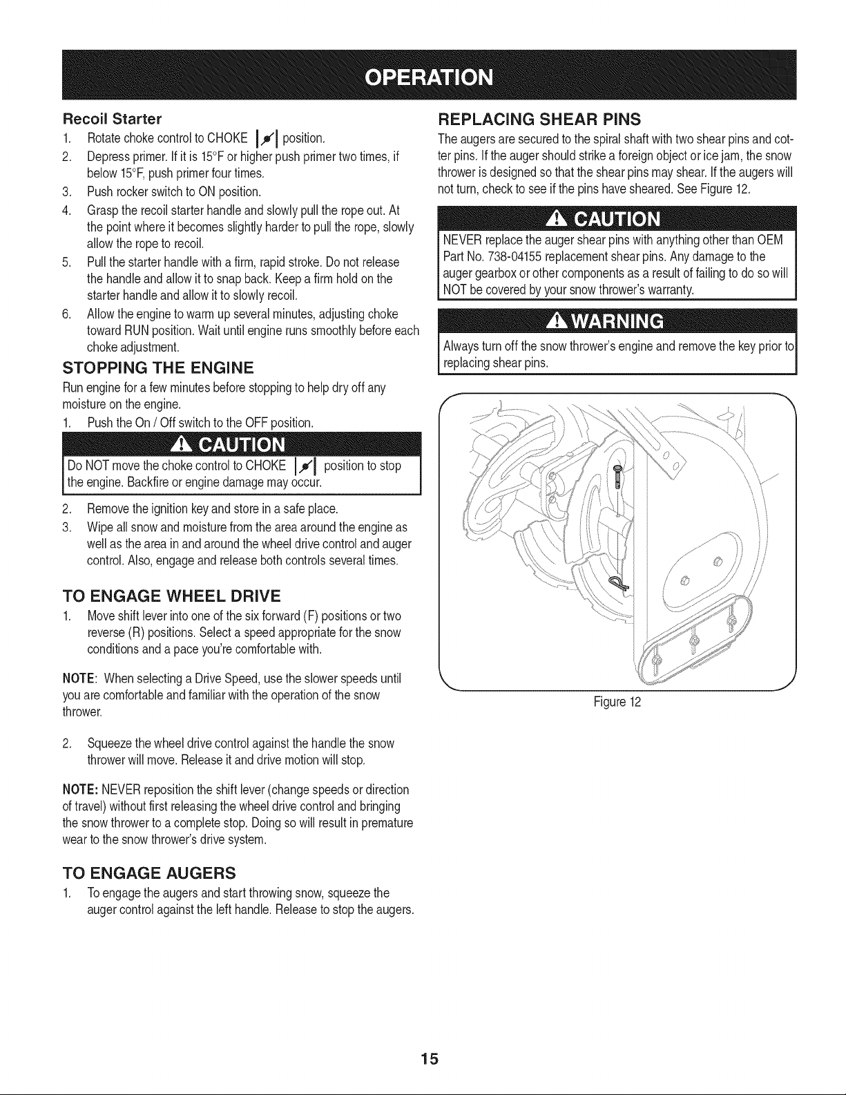
REPLACING SHEAR PINS
Theaugersaresecuredto thespiralshaftwithtwo shearpinsandcot-
terpins.Iftheaugershouldstrikea foreignobjectoricejam, thesnow
throwerisdesignedsothattheshearpinsmayshear.Iftheaugerswill
notturn,checkto seeifthepinshavesheared.SeeFigure12.
NEVERreplacetheaugershearpinswithanythingotherthanOEM
PartNo.738-04155replacementshearpins.Anydamagetothe
augergearboxorothercomponentsasaresultof failingtodosowill
NOTbecoveredbyyoursnowthrower'swarranty.
Alwaysturnoffthesnowthrower'sengineand removethekeypriorto
replacingshearpins.
f
ii
TO ENGAGE WHEEL DRIVE
1. Moveshiftleverintooneofthesixforward(F) positionsor two
reverse(R)positions.Selecta speedappropriateforthe snow
conditionsand a paceyou'recomfortablewith.
NOTE: Whenselectinga DriveSpeed,usetheslowerspeedsuntil
youarecomfortableandfamiliarwiththeoperationofthesnow
thrower.
2. Squeezethewheeldrivecontrolagainstthehandlethesnow
throwerwillmove.Releaseit anddrivemotionwillstop.
NOTE:NEVERrepositiontheshiftlever(changespeedsordirection
oftravel)withoutfirst releasingthewheeldrivecontrolandbringing
thesnowthrowertoa completestop.Doingsowillresultinpremature
wearto the snowthrower'sdrive system.
TO ENGAGE AUGERS
1. Toengagetheaugersandstartthrowingsnow,squeezethe
augercontrolagainsttheleft handle.Releasetostoptheaugers.
J
Figure12
15
ENGINE MAINTENANCE
f
Beforelubricating,repairing,or inspecting,disengageallcontrolsand
stopengine.Waituntilallmovingpartshavecometoa completestop.
Removetheignitionkeytopreventunintendedfiringoftheengine.
Checking Engine Oil
1. Besureengineisuprightand level
2. Unscrewoil fillcapfromoil fillertubeandwipedipstickclean.
3. Screwoil fillcapbackintooil fillertube.Tightensecurely.
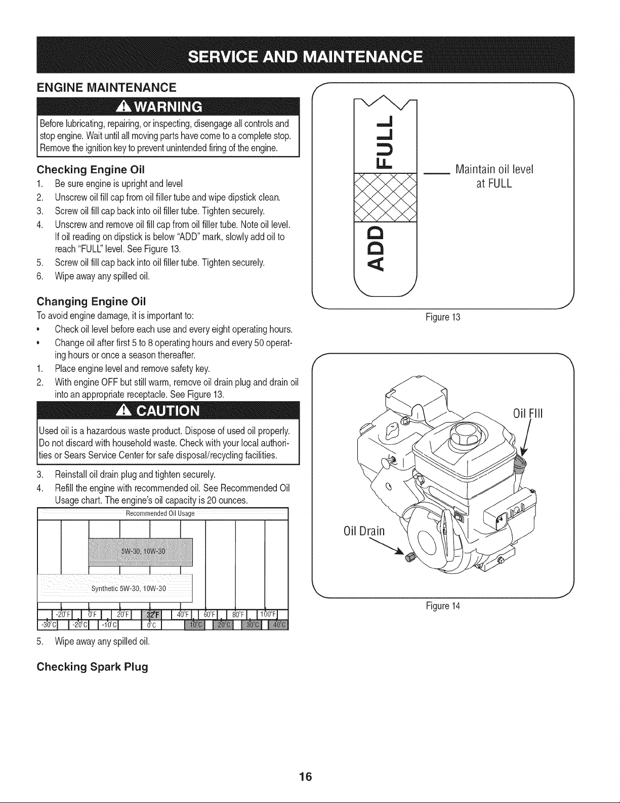
4. Unscrewand removeoilfillcapfromoilfillertube.Noteoillevel.
Ifoil readingondipstickisbelow"ADD"mark,slowlyaddoil to
reach"FULL"level.SeeFigure13.
5. Screwoil fillcapbackintooil fillertube.Tightensecurely.
6. Wipeawayany spilledoil.
Changing Engine Oil
Toavoidenginedamage,it isimportantto:
• Checkoil levelbeforeeachuseandeveryeightoperatinghours.
• Changeoil afterfirst5to 8operatinghoursandevery50operat-
inghoursor oncea seasonthereafter.
1. Placeenginelevelandremovesafetykey.
2. WithengineOFFbutstillwarm,removeoil drainpluganddrainoil
intoan appropriatereceptacle.SeeFigure13.
,.J
..J
LI..
Maintain oil level
at FULL
a
a
X._j
J
Figure13
f
Usedoilisahazardouswasteproduct.Disposeofusedoil properly.
IDonotdiscardwithhouseholdwaste.Checkwithyourlocalauthori-
_tiesor SearsServiceCenterforsafedisposal/recyclingfacilities.
3. Reinstalloildrainplugandtightensecurely.
4. Refilltheenginewith recommendedoil.SeeRecommendedOil
Usagechart.The engine'soilcapacityis20 ounces.
Recommended Oil Usage
i¸ i!i!i¸iii¸,!i!i
5. Wipeawayany spilledoil.
Checking Spark Plug
Oil Drain
Figure14
16
Checksparkplugyearlyor every100operatinghours.
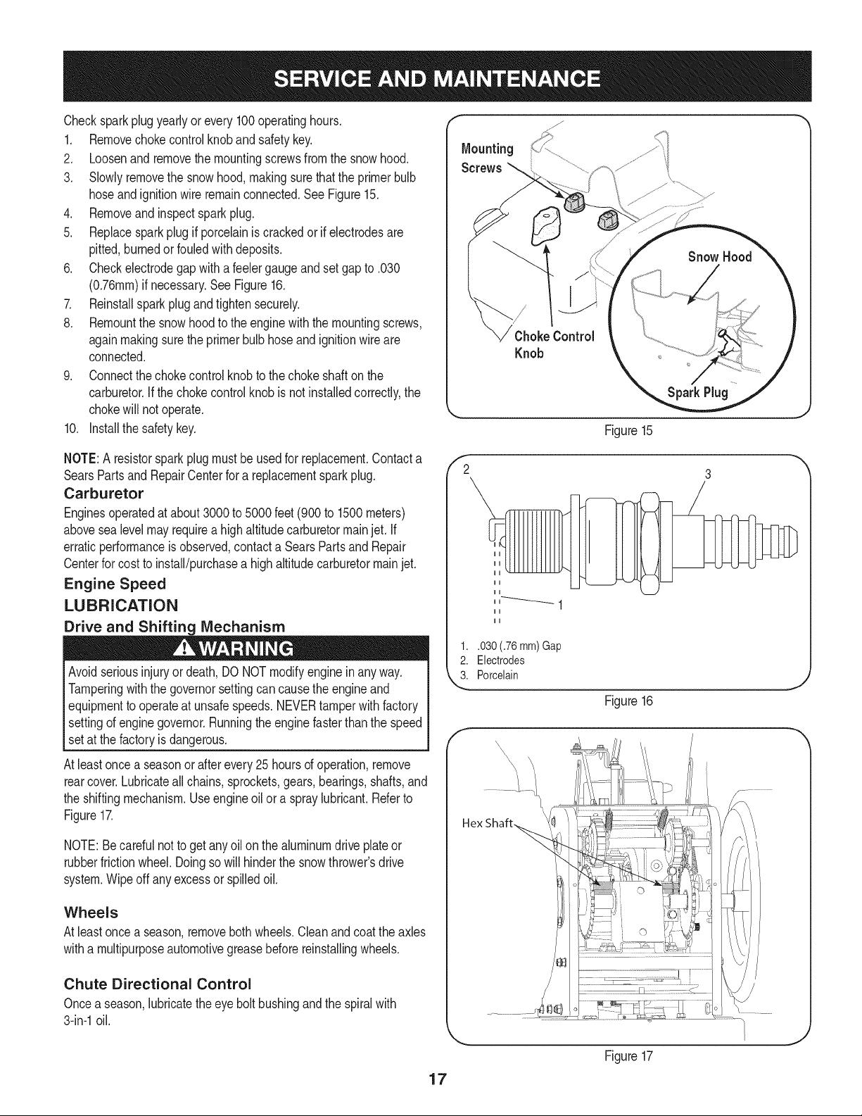
1. Removechokecontrolknobandsafetykey.
2. Loosenandremovethe mountingscrewsfromthesnowhood.
3. Slowlyremovethe snowhood,makingsurethattheprimerbulb
hoseandignitionwireremainconnected.SeeFigure15.
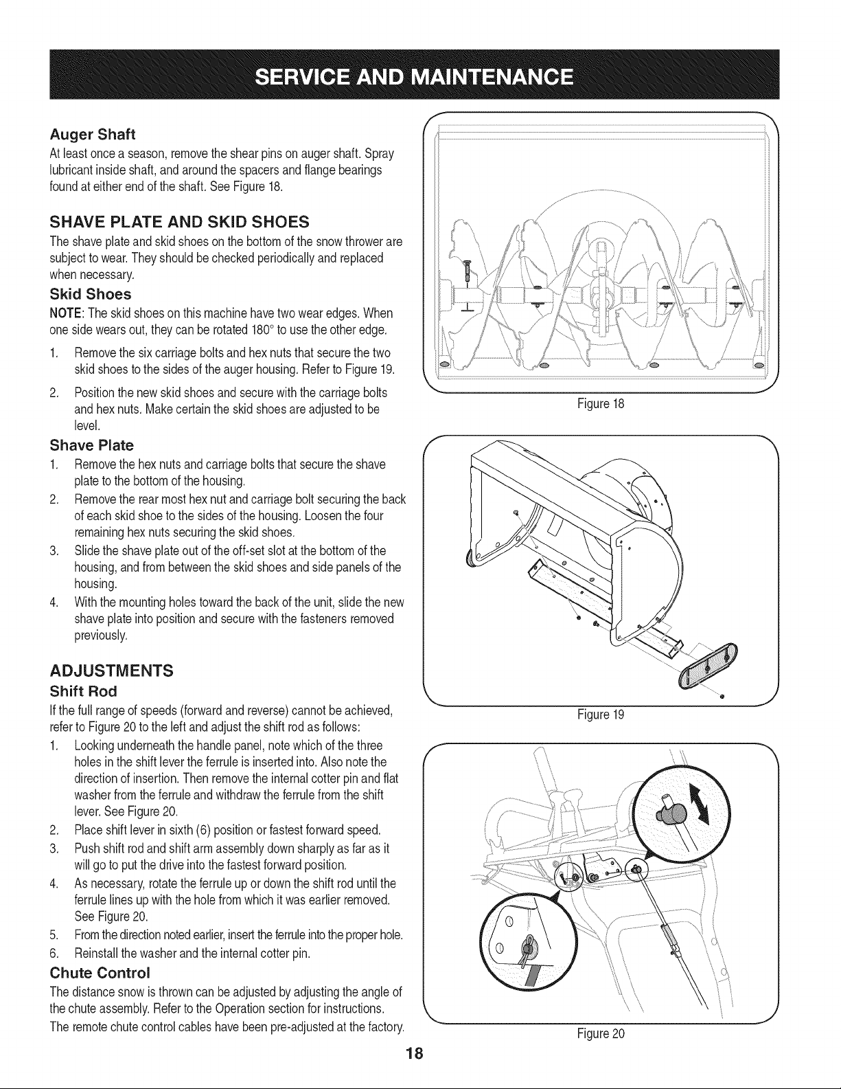
4. Removeandinspectsparkplug.
5. Replacesparkplugif porcelainis crackedorif electrodesare
pitted,burnedorfouledwithdeposits.
6. Checkelectrodegapwitha feelergaugeandsetgapto .030
(0.76ram)ifnecessary.SeeFigure16.
7. Reinstallsparkplugandtightensecurely.
8. Remountthe snowhoodtotheenginewith themountingscrews,
againmakingsurethe primerbulbhoseandignitionwireare
connected.
9. Connectthechokecontrolknobto thechokeshaftonthe
carburetor.Ifthechokecontrolknobis not installedcorrectly,the
chokewillnotoperate.
10. Installthe safetykey.
NOTE:A resistorsparkplugmustbeusedforreplacement.Contacta
SearsPartsand RepairCenterforareplacementsparkplug.
Carburetor
Enginesoperatedatabout3000to 5000feet(900to 1500meters)
abovesealevelmayrequireahighaltitudecarburetormainjet. If
erraticperformanceis observed,contacta SearsPartsand Repair
Centerforcostto install/purchasea highaltitudecarburetormainjet.
Engine Speed
LUBRICATION
Drive and Shifting Mechanism
Mounting
Screws
Knob
Figure15
Avoidseriousinjuryordeath,DONOTmodifyengineinanyway.
Tamperingwiththegovernorsettingcancausetheengineand
equipmenttooperateat unsafespeeds.NEVERtamperwithfactory
settingof enginegovernor.Runningtheenginefasterthanthespeed
setat thefactoryisdangerous.
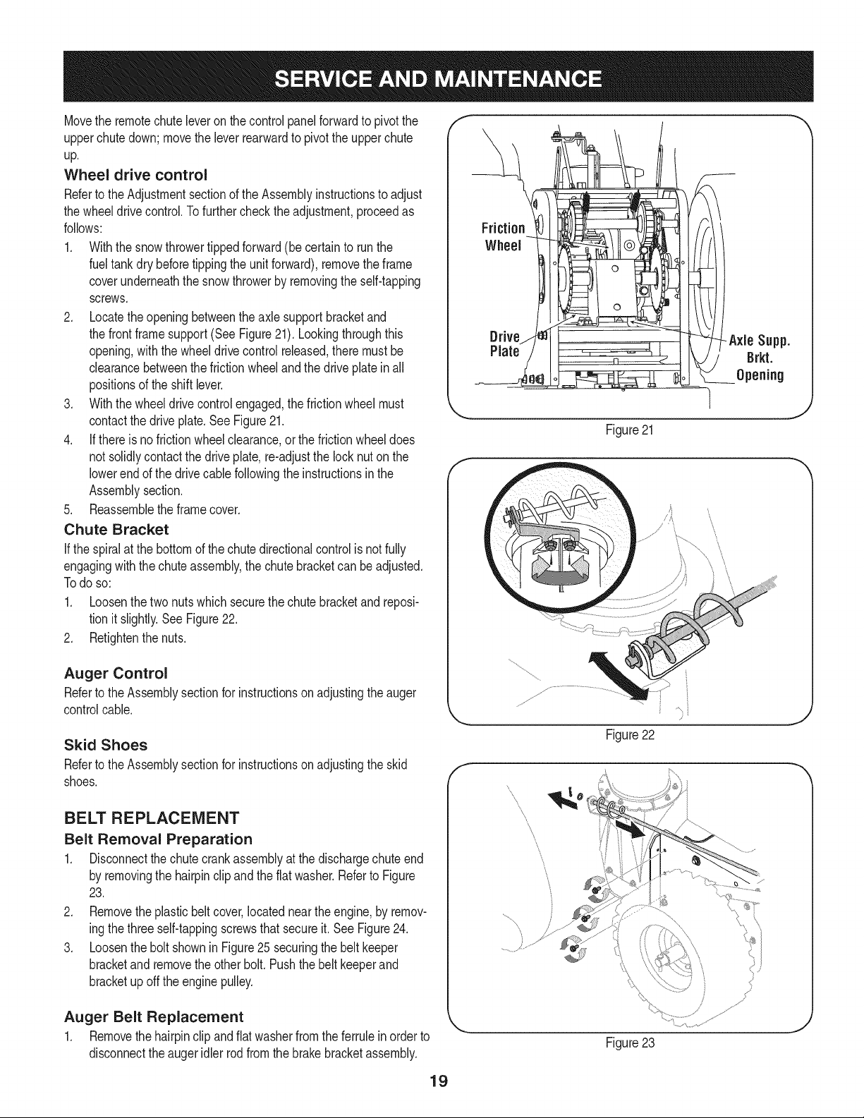
Atleastoncea seasonorafterevery25 hoursofoperation,remove
rearcover.Lubricateallchains,sprockets,gears,bearings,shafts,and
theshiftingmechanism.Useengineoil oraspraylubricant.Referto
Figure17.
NOTE:Becarefulnotto getanyoil on thealuminumdrive plateor
rubberfrictionwheel.Doingsowillhinderthesnowthrower'sdrive
system.Wipeoffanyexcessor spilledoil.
Wheels
Atleastoncea season,removeboth wheels.Cleanandcoattheaxles
withamultipurposeautomotivegreasebeforereinstallingwheels.
Chute Directional Control
Oncea season,lubricatethe eyeboltbushingandthe spiralwith
3-in-1oil.
Figure16
f
Figure17
17
Auger Shaft
Atleastonceaseason,removetheshearpinsonaugershaft.Spray
lubricantinsideshaft,andaroundthespacersandflangebearings
foundateitherendoftheshaft.SeeFigure18.
SHAVE PLATE AND SKID SHOES
Theshaveplateandskidshoesonthebottomofthesnowthrowerare
subjecttowear.Theyshouldbecheckedperiodicallyandreplaced
whennecessary.
Skid Shoes
NOTE:Theskidshoeson thismachinehavetwowearedges.When
onesidewearsout,theycanberotated1800to usetheotheredge.
1. Removethe sixcarriageboltsandhexnutsthatsecurethetwo
skidshoestothesidesoftheaugerhousing.RefertoFigure19.
2. Positionthe new skidshoesandsecurewiththecarriagebolts
andhexnuts.Makecertaintheskidshoesareadjustedtobe
level.
Shave Plate
1. Removethe hexnutsandcarriageboltsthatsecuretheshave
plateto the bottomof thehousing.
2. Removethe rearmosthexnutandcarriageboltsecuringthe back
ofeachskidshoetothe sidesofthehousing.Loosenthefour
remaininghexnutssecuringthe skidshoes.
3. Slidethe shaveplateoutoftheoff-setslotatthe bottomofthe
housing,andfrombetweentheskidshoesandsidepanelsofthe
housing.
4. Withthe mountingholestowardthebackoftheunit,slidethenew
shaveplateinto positionandsecurewiththefastenersremoved
previously.
/ /7 "'! ......_, .....
.............. _':'f!'t, .......... }_\_. _,
i _ \ .....77',!.1< ' L _k;,..... +El'\t;......
k, -Jr 7 r'W'i / '
, , _ ' ...... 7
....................,'r......................................\ i ........ +>, F .............................
J
Figure18
f
ADJUSTMENTS
Shift Rod
Ifthefull rangeofspeeds(forwardandreverse)cannotbe achieved,
referto Figure20totheleftandadjusttheshiftrodas follows:
1. Lookingunderneaththehandlepanel,notewhichof thethree
holesinthe shiftlevertheferruleis insertedinto.Alsonotethe
directionof insertion.Thenremovetheinternalcotterpinandflat
washerfromtheferruleandwithdrawtheferrulefromthe shift
lever.SeeFigure20.
2. Placeshift leverin sixth(6) positionor fastestforwardspeed.
3. Pushshift rodandshiftarmassemblydownsharplyas farasit
willgo toputthe driveintothefastestforwardposition.
4. Asnecessary,rotatetheferruleupor downthe shiftroduntilthe
ferrulelinesupwiththeholefromwhichit wasearlierremoved.
SeeFigure20.
5. Fromthedirectionnotedearlier,inserttheferruleintotheproperhole.
6. Reinstallthewasherandtheinternalcotterpin.
Chute Control
Thedistancesnowisthrowncanbeadjustedbyadjustingtheangleof
thechuteassembly.Referto theOperationsectionforinstructions.
Theremotechutecontrolcableshavebeenpreladjustedat the factory.
18
Figure19
f
t,
'ii /
Figure20
Movetheremotechuteleveronthecontrolpanelforwardtopivotthe
upperchutedown;movetheleverrearwardtopivottheupperchute
up,
Wheeldrive control
RefertotheAdjustmentsectionoftheAssemblyinstructionstoadjust
thewheeldrivecontrol,Tofurtherchecktheadjustment,proceedas
follows:
1. Withthesnowthrowertippedforward(becertaintorunthe
fueltankdrybeforetippingtheunitforward),removetheframe
coverunderneaththesnowthrowerbyremovingtheself-tapping
screws.
2. Locatetheopeningbetweentheaxlesupportbracketand
thefrontframesupport(SeeFigure21).Lookingthroughthis
opening,withthewheeldrivecontrolreleased,theremustbe
clearancebetweenthefrictionwheelandthedriveplateinall
positionsoftheshiftlever.
3. Withthewheeldrivecontrolengaged,thefrictionwheelmust
contactthedriveplate.SeeFigure21.
4. Ifthereisnofrictionwheelclearance,orthefrictionwheeldoes
notsolidlycontactthedriveplate,re-adjustthelocknutonthe
lowerendofthedrivecablefollowingtheinstructionsinthe
Assemblysection.
5. Reassembletheframecover.
Chute Bracket
Ifthespiralatthebottomofthechutedirectionalcontrolisnotfully
engagingwiththechuteassembly,the chutebracketcanbeadjusted.
Todo so:
1. Loosenthetwonutswhichsecurethechutebracketandreposi-
tionitslightly.See Figure22.
2. Retightenthenuts.
Drive Axle Supp.
Plate Brkt.
Opening
Figure21
l
Auger Control
RefertotheAssemblysectionforinstructionsonadjustingtheauger
controlcable.
Skid Shoes
RefertotheAssemblysectionforinstructionsonadjustingtheskid
shoes.
BELT REPLACEMENT
Belt Removal Preparation
1. Disconnectthechutecrankassemblyatthedischargechuteend
byremovingthe hairpinclipandtheflatwasher.Referto Figure
23.
2. Removetheplasticbelt cover,locatednearthe engine,byremov-
ingthethreeself-tappingscrewsthatsecureit.SeeFigure24.
3. Loosentheboltshownin Figure25 securingthebeltkeeper
bracketandremovetheotherbolt.Pushthebeltkeeperand
bracketupoff theenginepulley.
Auger Belt Replacement
1. Removethehairpinclipandflatwasherfromtheferrulein orderto
disconnecttheaugeridlerrodfromthebrakebracketassembly.
j_
Figure22
f
Figure23
19

Figure24
SeeFigure26.
NOTE:Makesurethatthe locationoftheferruleontheauger
idlerrodis maintained.
2. Sliptheaugercontrolbelt(thefrontbelt)offtheenginepulley.
3. Pullthebrakebracketassemblytowardsthecableguideroller
andunhooktheaugercable"Z"fitting.See Figure27.
4. Frombothsidesofthe the frameassembly,usea 1/2"wrenchto
removethethreehextapscrewssecuringtheframetothe auger
housingassembly.Referto Figure23on previouspage.
NOTE:Do not removethelowerhexflangelocknuton eachside.
5. Placeablockofwoodunderneaththe augerhousingasshownin
Figure28andseparateaugerhousingfromtheframebytiltingthe
housingforwardandpullingupthe handles.
6. Blocktheimpellerwithapieceofwoodto preventit fromspinning
andusea 1/2"wrenchto removethe hexscrewandflatwasher
fromthecenterofthe pulleyontheaugerhousing.See Figure29.
7. Liftthebrakebracketassemblyoutofthe pulleygrooveandslide
thepulleyassemblyoffthe postsofthe augerpulleyadapterto
removetheoldbelt.RefertoFigure29.
NOTE:Thepulleyadaptermayslideoffthe augerinputshaftwhen
removingthepulley.Useextracautiontoensuretheadapterdoesfall
and/orget damagedwhenremovingthepulley.
8. Placethe newaugerbeltin theV-grooveoftheaugerpulleyand
placethe pulleyw/beltinsidethebeltkeepers.
9. Turnthepulleyasnecessarytoalignitsthreeslotsapproximately
withthepostsofthepulleyadapter,thenmovethebrakebracket
assemblyawayfromtheinputshaft. Whilealigningthe pulley
slotsandadapterposts,pushtheaugerpulleyfullyontothe
adapter.Referto Figure29.
NOTE: If thepulleyadapterwas removedwiththepulley,alignthe
splinesofthepulleyadapterandaugerinputshaft,andpushthepulley
andadapterontotheinputshaft.Referto Figure29.
10. Slidethewasherontothe hex screwremovedearlierandapply
Loctite262to the threadsofthehexscrew.
11. Insertthe hexscrewthroughthepulleyassemblyandintothe
Loosen
Figure25
//
Figure26
f
/
//
/
/
Figure27
20
threadsoftheinputshaft.Torquethehexscrewto250-325in.
/Ibs.tosecuretheaugerpulleyassemblyonthe input shaft.
12. If alsoreplacingthe drivebelt,proceedtothe"DriveBelt"
instruction.If not,repositionthetransmissionframebackonto
theaugerhousing.Installthe drivebeltontheenginepulley,
re-connectthe augercable"Z" fittingandaugeridlerrodferrule
tothebrakebracket.Repositionandsecuretheenginepulley
beltguard,andre-installthebeltcover.
NOTE:Makesureto removethepieceofwoodblockingtheimpeller.
Checktheaugerdrivebeltadjustment.Withtheaugerclutch lever
in thedisengagedposition,thetop surfaceofthenewbelt shouldbe
evenwiththeoutsidediameterof thepulley.
Toadjust,disconnectferrulefrombrakebracketassembly.Thread
ferrulein(towardsidler)to increasetensionon belt,oroutto decrease
belttension.
NOTE:Thebrakepuckmustalwaysbefirmlyseatedinthe pulley
groovewhenaugercontrolisdisengaged.
IMPORTANT:Repeatthe "AugerDriveControlTest"fromtheAs-
semblysectionbeforeoperatingsnowthrower.
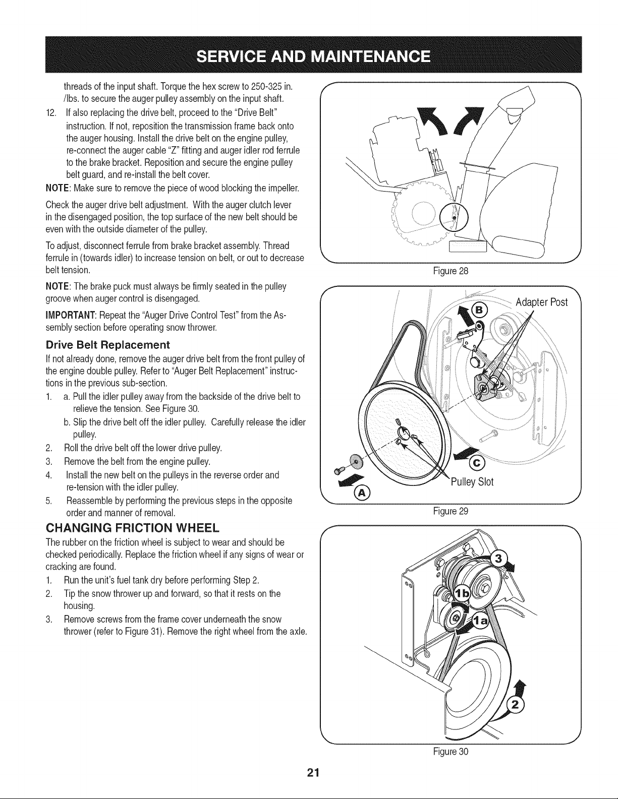
Drive Belt Replacement
If notalreadydone,removethe augerdrivebeltfromthefrontpulleyof
theenginedoublepulley.Referto"AugerBeltReplacement"instruc-
tionsintheprevioussub-section.
1. a.Pulltheidlerpulleyawayfromthebacksideof thedrivebeltto
relievethetension.SeeFigure30.
b.Slipthedrivebelt offtheidlerpulley.Carefullyreleasetheidler
pulley.
2. Rollthedrivebeltoff thelowerdrivepulley.
3. Removethebeltfromtheenginepulley.
4. Installthenewbeltonthepulleysinthereverseorderand
re-tensionwiththeidlerpulley.
5. Reassemblebyperformingthepreviousstepsintheopposite
orderandmannerof removal.
CHANGING FRICTION WHEEL
Therubberonthefrictionwheelissubjectto wearand shouldbe
checkedperiodically.Replacethefrictionwheelifany signsofwearor
crackingarefound.
1. Runtheunit'sfueltankdrybeforeperformingStep2.
2. Tipthesnowthrowerupandforward,so thatitrestsonthe
housing.
3. Removescrewsfromtheframecoverunderneaththesnow
thrower(referto Figure31).Removetherightwheelfromtheaxle.
Figure28
Adapter Post
Slot
Figure29
f
21
Figure30
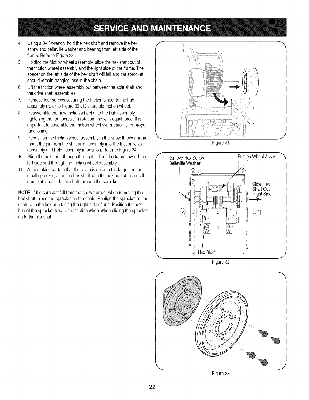
4. Usinga 3/4"wrench,holdthehexshaftandremovethehex
screwandbellevillewasherandbearingfromleft sideofthe
frame.Referto Figure32.
5. Holdingthefrictionwheelassembly,slidethe hex shaftoutof
thefrictionwheelassemblyandtherightsideoftheframe.The
spacerontheleftsideofthehexshaftwill fallandthesprocket
shouldremainhanginglosein thechain.
6. Liftthefrictionwheelassemblyout betweentheaxleshaftand
thedrive shaftassemblies.
7. Removefourscrewssecuringthefrictionwheeltothehub
assembly(refertoFigure33).Discardoldfrictionwheel.
8. Reassemblethenewfrictionwheelontothehubassembly,
tighteningthefourscrewsinrotationandwith equalforce.It is
importanttoassemblethefrictionwheelsymmetricallyfor proper
functioning.
9. Repositionthefrictionwheelassemblyin the snowthrowerframe.
Insertthe pinfromtheshiftarm assemblyintothe frictionwheel
assemblyandholdassemblyin position.Referto Figure34.
10. Slidethe hexshaftthroughthe rightsideoftheframetowardthe
leftsideandthroughthefrictionwheelassembly.
11. Aftermakingcertainthatthechainison boththe largeandthe
smallsprocket,alignthehexshaftwiththehexhubof thesmall
sprocket,andslidetheshaftthroughthe sprocket.
NOTE:If thesprocketfellfromthesnowthrowerwhileremovingthe
hexshaft,placethe sprocketon thechain.Realignthesprocketon the
chainwiththehexhubfacingthe rightsideof unit.Positionthehex
hubofthesprockettowardthefrictionwheelwhenslidingthesprocket
ontothehexshaft.
RemoveHexScrew
BellevilleWasher
l°
Figure31
FrictionWheelAss'y.
/
SlideHex
ShaftOut
RightSide
22
HexShaft
J
Figure32
f
Figure33
 Loading...