

Craftsman 247888300 Owner’s Manual
Operator's Manual
P R 0 F E S S I 0 N A
30" SNOW THROWER
Model No. 247.88830
o SAFETY
ASSEMBLY
OPERATION
MAINTENANCE
CAUTION: Before using
this product, read this
PARTS LIST
o ESPANOL
manual and follow all
safety rules and operating
instructions.
Sears Brands Management Corporation, Hoffman Estates, IL 60179, U.S.A.
Visit our website: www.craftsman.com FORM1/0.769-05137C
8/06/2010
WarrantyStatement.................... Page2
SafeOperationPractices.............. Pages3-6
SafetyLabels......................... Page7
Assembly......................... Pages8-13
Operation........................ Pages14-17
Service&Maintenance.............. Pages18-23
Off-SeasonStorage................... Page24
Troubleshooting...................... Page25
PartsList......................... Pages26-36
RepairProtectionAgreement............ Page41
Espa_ol............................. Page42
ServiceNumbers................... BackPage
CRAFTSMANPROFESSIONAL TWO YEAR FULL WARRANTY
FORTWOYEARSfromthedateofpurchase,this productis warrantedagainstanydefectsin materialorworkmanship.Defectiveproductwill
receivefreerepairor freereplacementif repairis unavailable.
Thiswarrantyappliesforonlyone yearfromthe dateof purchaseifthisproductiseverusedwhileprovidingcommercialservicesorif rentedto
anotherperson.
Forwarranty coverage details to obtain repairor replacement,visit the web site: www.craftsman.com
This warranty covers ONLYdefects in materialandworkmanship. Warrantycoverage does not include:
• Expendableitemsthatcanwearoutfromnormalusewithinthewarrantyperiod,includingbutnotlimitedtoaugers,augerpaddies,drift
cutters,skidshoes,shaveplate,shearpins,sparkplug,aircleaner,belts,andoil filter.
• Standardmaintenanceservicing,oilchanges,ortune-ups.
Tirereplacementor repaircausedbypuncturesfromoutsideobjects,suchasnails,thorns,stumps,orglass.
Tireor wheelreplacementor repairresultingfromnormalwear,accident,orimproperoperationor maintenance.
Repairsnecessarybecauseof operatorabuse,includingbutnotlimitedtodamagecausedbyover-speedingthe engine,or fromimpacting
objectsthatbendthe frame,augershaft,etc.
• Repairsnecessarybecauseof operatornegligence,includingbutnot limitedto,electricalandmechanicaldamagecausedbyimproper
storage,failureto usethepropergradeandamountofengineoil,or failureto maintaintheequipmentaccordingtotheinstructionscontained
intheoperator'smanual.
• Engine(fuelsystem)cleaningor repairscausedbyfueldeterminedto becontaminatedoroxidized(stale).in general,fuelshouldbeused
within30 daysof itspurchasedate.
Normaldeteriorationandwearof the exteriorfinishes,orproductlabelreplacement.
Thiswarrantygivesyouspecificlegalrights,andyoumayalsohaveotherrightswhichvaryfromstateto state.
Sears BrandsManagementCorporation, Hoffman Estates, IL 60179
EngineOilType: SAE5W-30
EngineOilCapacity: 37ounces
FuelCapacity: Approx.5Quarts
SparkPlug: TorchF6RTC
SparkPlugGap: .020"to .030"
©SearsBrands,LLC
ModelNumber.................................................................
Serial Number.................................................................
Dateof Purchase .............................................................
Recordthemodelnumber,serialnumber
anddateof purchaseabove
2
Thissymbolpointsoutimportantsafetyinstructionswhich,if not
followed,couldendangerthepersonalsafetyand/orpropertyof
yourselfandothers. Readandfollowall instructionsin thismanual
beforeattemptingto operatethismachine.Failuretocomplywith
theseinstructionsmayresultin personalinjury.Whenyou seethis
symbol,HEEDITSWARNING!
Thismachinewasbuilttobeoperatedaccordingtothesafeopera-
tionpracticesinthis manual.Aswithanytypeof powerequipment,
carelessnessorerroron thepartoftheoperatorcanresultin serious
injury.Thismachineiscapableofamputatingfingers,hands,toes
andfeetandthrowingdebris.Failuretoobservethe followingsafety
instructionscouldresultin seriousinjuryor death.
CALIFORNIA PROPOSITION 65
EngineExhaust,someof itsconstituents,andcertainvehicle
componentscontainoremitchemicalsknownto Stateof California
tocausecancerandbirthdefectsorotherreproductiveharm,
TRAiNiNG
• Read,understand,andfollowall instructionsonthe machineand
in themanual(s)beforeattemptingto assembleandoperate.
Failuretodo socan resultinseriousinjurytothe operatorand/
orbystanders.Keepthismanualin a safeplaceforfutureand
regularreferenceandfor orderingreplacementparts.Forques-
tionscall,1-800-4MY-HOME.
• Befamiliarwithall controlsandtheir properoperation.Knowhow
tostopthemachineanddisengagethemquickly.
Neverallowchildrenunder14yearsofageto operatethis
machine.Children14andover shouldreadandunderstandthe
instructionsandsafeoperationpracticesin thismanualandon
themachineandbe trainedandsupervisedbyanadult.
Neverallowadultsto operatethis machinewithoutproper
instruction.
• Thrownobjectscancauseseriouspersonalinjury.Planyour
snow-throwingpatterntoavoiddischargeof materialtoward
roads,bystandersandthe like.
Keepbystanders,petsandchildrenat least75feetfromthe
machinewhileitisinoperation.Stopmachineifanyoneenters
thearea.
Exercisecautiontoavoidslippingor falling,especiallywhen
operatinginreverse.
Your Responsibility--Restrict theuseof this powermachineto
personswhoread,understandandfollowthewarningsand instruc-
tionsin thismanualandon themachine,
SAVE THESE INSTRUCTIONS!
PREPARATION
Thoroughlyinspecttheareawheretheequipmentis to beused.
Removeall doormats,newspapers,sleds,boards,wiresandother
foreignobjects,whichcouldbe trippedoverorthrownbytheauger/
impeller.
Alwayswearsafetyglassesoreyeshieldsduringoperationand
whileperformingan adjustmentor repairto protectyoureyes.
Thrownobjectswhichricochetcancauseseriousinjuryto the
eyes.
Donot operatewithoutwearingadequatewinteroutergarments.
Donot wearjewelry,longscarvesorotherlooseclothing,which
couldbecomeentangledinmovingparts.Wearfootwearwhich
willimprovefootingonslipperysurfaces.
Usea groundedthree-wireextensioncordand receptacleforall
machineswithelectricstartengines.
Disengageall controlleversbeforestartingtheengine.
Adjustcollectorhousingheighttocleargravelorcrushedrock
surfaces.
Neverattempttomakeanyadjustmentswhileengineis running,
exceptwherespecificallyrecommendedinthe operator'smanual.
Letengineandmachineadjustto outdoortemperaturebefore
startingtoclearsnow.
3
SafeHandling of Gasoline
Toavoidpersonalinjuryor propertydamageuseextremecarein
handlinggasoline.Gasolineisextremelyflammableandthevaporsare
explosive.Seriouspersonalinjurycanoccurwhengasolineisspilled
onyourselforyourclotheswhichcanignite.Washyourskinand
changeclothesimmediately.
• Useonlyanapprovedgasolinecontainer.
• Extinguishall cigarettes,cigars,pipesandothersources
ofignition.
• Neverfuelmachineindoors.
• Neverremovegascapor addfuel whiletheengineishot
or running.
• Allowengineto coolat leasttwo minutesbeforerefueling.
• Neveroverfill fueltank.Filltanktono morethan1/2inch
belowbottomoffiller neckto providespacefor fuel
expansion.
• Replacegasolinecapandtightensecurely.
• Ifgasolineis spilled,wipeit offtheengineandequipment.
Movemachinetoanotherarea.Wait5 minutesbefore
startingtheengine.
• Neverstorethemachineorfuelcontainerinsidewhere
thereis anopenflame,sparkor pilotlight(e.g.furnace,
waterheater,spaceheater,clothesdryeretc.).
• Allowmachinetocoolatleast5 minutesbeforestoring.
• Neverfillcontainersinsidea vehicleorona truckor trailer
bedwitha plasticliner.Alwaysplacecontainersonthe
groundawayfromyourvehiclebeforefilling.
• If possible,removegas-poweredequipmentfromthetruck
ortrailerandrefueliton theground.Ifthisisnotpossible,
thenrefuelsuchequipmentona trailerwitha portable
container,ratherthanfromagasolinedispensernozzle.
• Keepthenozzleincontactwiththe rimofthefueltankor
containeropeningatalltimesuntilfuelingis complete.Do
notuse a nozzlelock-opendevice.
OPERATION
• Do not puthandsorfeetnear rotatingparts,intheauger/impeller
housingorchuteassembly.Contactwiththe rotatingpartscan
amputatehandsandfeet.
• Theauger/impellercontrolleverisa safetydevice.Neverbypass
itsoperation.Doingsomakesthemachineunsafeandmaycause
personalinjury.
• Thecontrolleversmustoperateeasilyinbothdirectionsand
automaticallyreturntothedisengagedpositionwhenreleased.
• Neveroperatewitha missingordamagedchuteassembly.Keep
all safetydevicesin placeandworking.
• Neverrunanengineindoorsorina poorlyventilatedarea.Engine
exhaustcontainscarbonmonoxide,anodorlessanddeadlygas.
• Do notoperatemachinewhileundertheinfluenceofalcoholor
drugs.
• Mufflerandenginebecomehotandcancausea burn.Do not
touch.Keepchildrenaway.
• Exerciseextremecautionwhenoperatingon orcrossinggravel
surfaces.Stayalertforhiddenhazardsor traffic.
• Exercisecautionwhenchangingdirectionandwhileoperatingon
slopes.
• Planyoursnow-throwingpatternto avoiddischargetowards
windows,walls,carsetc.Thus,avoidingpossibleproperty
damageorpersonalinjurycausedby a ricochet.
• Neverdirectdischargeatchildren,bystandersand petsor allow
anyoneinfrontofthemachine.
• Donot overloadmachinecapacitybyattemptingto clearsnowat
toofastof arate.
• Neveroperatethismachinewithoutgoodvisibilityorlight.Always
be sureofyourfootingandkeepafirmholdon the handles.Walk,
neverrun.
• Disengagepowerto theauger/impellerwhentransportingor not
in use.
• Neveroperatemachineathightransportspeedsonslippery
surfaces.Lookdownand behindand usecare whenbackingup.
• Ifthemachineshouldstarttovibrateabnormally,stoptheengine,
disconnectthesparkplugwire andgroundit againstthe engine.
Inspectthoroughlyfor damage.Repairanydamagebefore
startingandoperating.
• Disengageall controlleversandstopenginebeforeyouleave
theoperatingposition(behindthehandles).Waituntiltheauger/
impellercomestoa completestopbeforeuncloggingthechute
assembly,makingany adjustments,or inspections.
• Neverputyourhandinthedischargeor collectoropenings.Do
notunclogchuteassemblywhileengineisrunning.Shutoff
engineand remainbehindhandlesuntilall movingpartshave
stoppedbeforeunclogging.
• Useonlyattachmentsandaccessoriesapprovedbythemanufac-
turer(e.g.wheelweights,tirechains,cabsetc.).
• Whenstartingengine,pullcordslowlyuntilresistanceisfelt,then
pull rapidly.Rapidretractionofstartercord(kickback)willpull
handandarmtowardenginefasterthan youcanletgo.Broken
bones,fractures,bruisesorsprainscouldresult.
• Ifsituationsoccurwhichare notcoveredinthis manual,usecare
andgoodjudgment.ContactCustomerSupportforassistance
andthenameof your nearestservicingdealer.
CLEARING A CLOGGED DISCHARGE CHUTE
Handcontactwiththe rotatingimpellerinsidethe dischargechute
is themostcommoncauseofinjuryassociatedwithsnowthrowers.
Neveruseyourhandtocleanout thedischargechute.
Toclear thechute:
1. SHUTTHEENGINEOFF!
2. Wait 10secondstobe suretheimpellerbladeshavestopped
rotating.
3. Alwaysusea clean-outtool,not yourhands.
4
MAINTENANCE & STORAGE
• Nevertamperwithsafetydevices.Checktheirproperoperation
regularly.Refertothemaintenanceandadjustmentsectionsof
thismanual.
• Beforecleaning,repairing,or inspectingmachinedisengageall
controlleversandstoptheengine.Waituntilthe auger/impeller
cometoa completestop.Disconnectthe sparkplugwireand
groundagainsttheengineto preventunintendedstarting.
Checkboltsand screwsfor propertightnessat frequentintervals
tokeepthe machineinsafeworkingcondition.Also,visually
inspectmachineforanydamage.
Donotchangetheenginegovernorsettingor over-speedthe
engine.Thegovernorcontrolsthe maximumsafeoperatingspeed
oftheengine.
Snowthrowershaveplatesandskidshoesaresubjecttowear
anddamage.Foryoursafetyprotection,frequentlycheckall
componentsand replacewithoriginalequipmentmanufacturer's
(OEM)partsonly."Useofpartswhichdo not meetthe original
equipmentspecificationsmayleadto improperperformanceand
compromisesafety!"
Checkcontrolleversperiodicallytoverifytheyengageanddisen-
gageproperlyandadjust,ifnecessary.Refertotheadjustment
sectioninthisoperator'smanualforinstructions.
Maintainor replacesafetyandinstructionlabels,asnecessary.
• Observeproperdisposallawsand regulationsforgas,oil,etc.to
protecttheenvironment.
Priorto storing,runmachinea few minutestoclearsnowfrom
machineand preventfreezeupof auger/impeller.
Neverstorethemachineorfuelcontainerinsidewherethereisan
openflame,sparkorpilotlightsuchasa waterheater,furnace,
clothesdryeretc.
Alwaysrefertothe operator'smanualforproperinstructionson
off-seasonstorage.
Checkfuelline,tank, cap,andfittingsfrequentlyforcracksor
leaks.Replaceif necessary.
Donotcrankenginewithsparkplugremoved.
AccordingtotheConsumerProductsSafetyCommission(CPSC)
andtheU.S.EnvironmentalProtectionAgency(EPA),thisproduct
hasan AverageUsefulLifeof seven(7)years,or 60 hoursof
operation.Attheendof theAverageUsefulLifehavethemachine
inspectedannuallybyan authorizedservicedealertoensurethat
allmechanicalandsafetysystemsareworkingproperlyand not
wornexcessively.Failuretodo so can resultinaccidents,injuries
ordeath.
DO NOT MODIFY ENGINE
Toavoidseriousinjuryor death,do notmodifyengineinanyway.
Tamperingwiththegovernorsettingcanleadtoa runawayengineand
causeittooperateat unsafespeeds.Nevertamperwithfactorysetting
ofenginegovernor.
NOTICE REGARDING EMiSSiONS
EngineswhicharecertifiedtocomplywithCaliforniaandfederal
EPAemissionregulationsforSORE(SmallOffRoadEquipment)are
certifiedto operateon regularunleadedgasoline,and mayinclude
thefollowingemissioncontrolsystems:EngineModification(EM),
OxidizingCatalyst(OC),SecondaryAirInjection(SAI)and ThreeWay
Catalyst(TWO)if soequipped.
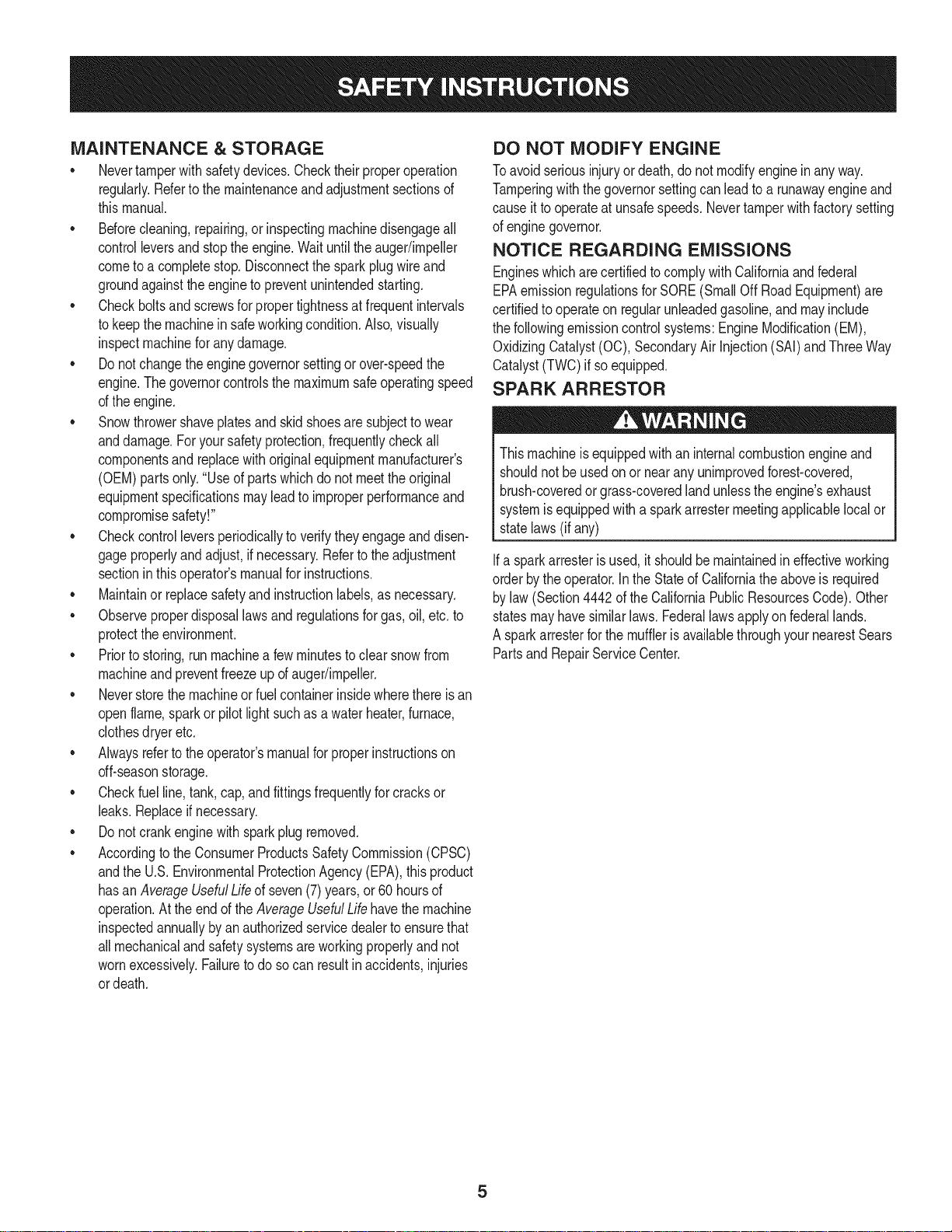
SPARK ARRESTOR
Thismachineisequippedwithaninternalcombustionengineand
shouldnotbe usedonor nearanyunimprovedforest-covered,
brush-coveredorgrass-coveredlandunlesstheengine'sexhaust
systemisequippedwitha sparkarrestermeetingapplicablelocalor
statelaws(if any)
Ifa sparkattesterisused,itshouldbemaintainedin effectiveworking
orderbytheoperator.IntheStateof Californiatheaboveis required
bylaw (Section4442of the CaliforniaPublicResourcesCode).Other
statesmayhavesimilarlaws. Federallawsapplyonfederallands.
A sparkarresterforthemufflerisavailablethroughyournearestSears
PartsandRepairServiceCenter.

SAFETY SYMBOLS
Thispagedepictsanddescribessafetysymbolsthatmayappearonthisproduct. Read,understand,andfollowall instructionson the machine
beforeattemptingto assembleandoperate.
READ THE OPERATOR'S MANUAL(S)
i
. +
i
Read, understand, and follow all instructions in the manual(s) before attempting to assemble and
operate
WARNING-- ROTATING BLADES
Keep hands out of inlet and discharge openings while machine is running. There are rotating blades
inside
WARNING-- ROTATING BLADES
Keep hands out of inlet and discharge openings while machine is running. There are rotating blades
inside
WARNING-- ROTATING AUGER
Do not put hands or feet near rotating parts, in the auger/impeller housing or chute assembly.
Contact with the rotating parts can amputate hands and feet.
'JIp
WARNING--THROWN OBJECTS
This machine may pick up and throw objects which can cause serious personal injury.
WARNING--GASOLINE IS FLAMMABLE
Allow the engine to cool at least two minutes before refueling.
WARNING-- CARBON MONOXIDE
Never run an engine indoors or in a poorly ventilated area. Engine exhaust contains carbon
monoxide, an odorless and deadly gas+
WARNING-- ELECTRICAL SHOCK
Do not use the engine's electric starter in the rain
6

lOOJ.,J.IlO=NV]10
"lVflNV_ S,UOJLVU3dOQV3H"_
N3HMNOIJ,RVOVtdJ,X33Sll"SU3QNVIS18IV30UVH3SBQ
13:lUiOH:IA:IN'S3iURrNIS13]F80NMOUHIQIOAV01 "t_
:IUO:J3gQ3dd01S3MH S.LUVd9HJAOI_1WlJlHn S31QNVH
QNIH38NiV_:t_lQNV'::lNiON::ldOlS'SH3A:rlH31R133OVON:lSl(]"_
":11AH33OSVHOSiQ90"13NI301 1001 lflO=NV:rl3:lSfl"_
"1:13dQNV8QHVH:11vlrld_VHVOU39flV}JO_13l13dL_lHJ,IM
IOVlN03"U3911VQNV1:131"13dlAIJ9NllVlOldINO_J:J)_VMVd:13)t"L
"S33VdUnS13AVU9NOgNilVU:ldO
"_]NiHOV_9Ni31Atd_SUO9NI99013NI'I
7
NOTE:Referencesto rightorleft sideof the snowthrowerare
determinedfrombehindtheunitintheoperatingposition(standing
directlybehindthesnowthrower,facingthe handlepanel).
REMOVING FROM CARTON
1. Cutthecornersofthecartonandlaythesidesflaton theground.
Removeanddiscardallpackinginserts.
2. Movethesnowthroweroutofthecarton.
3. Makecertainthecartonhasbeencompletelyemptiedbefore
discardingit.
ASSEMBLY
1. Observethe lowerrearareaof the snowthrowerto besure both
cablesarealignedwith rollerguidesbeforepivotingthehandle
upward.
a. Placethe shiftleverin the F6position.
b. Pullupandbackon upperhandleasshownin Figure1.As
youare raisingthehandleupward,makesurethatbothends
ofthecentercablearepositionedproperlyinthebrackets.
Alignupperhandlewiththelowerhandle.
c. Tightenhandknobssecuringupperhandleto lowerhandle.
Removeanddiscardanyrubberbands,ifpresent.Theyare
forpackagingpurposesonly.
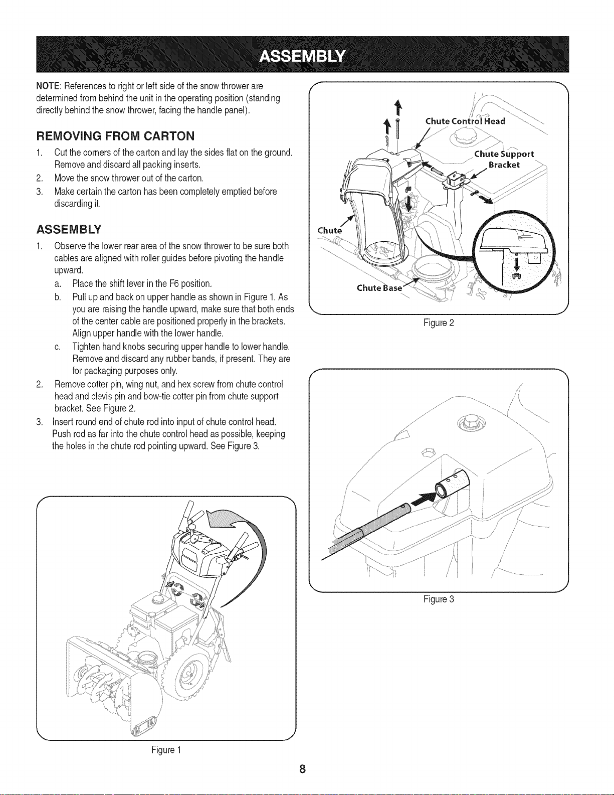
2. Removecotterpin,wing nut,andhexscrewfromchutecontrol
headandclevispinandbow-tiecotterpinfromchutesupport
bracket.SeeFigure2.
3. Insertroundendofchuterodinto inputofchutecontrolhead.
Pushrodas far intothechutecontrolheadas possible,keeping
theholesinthe chuterodpointingupward.SeeFigure3.
t
Chute Control Head
Chute
Figure2
f
// .....
%
Figure1
Figure3
8
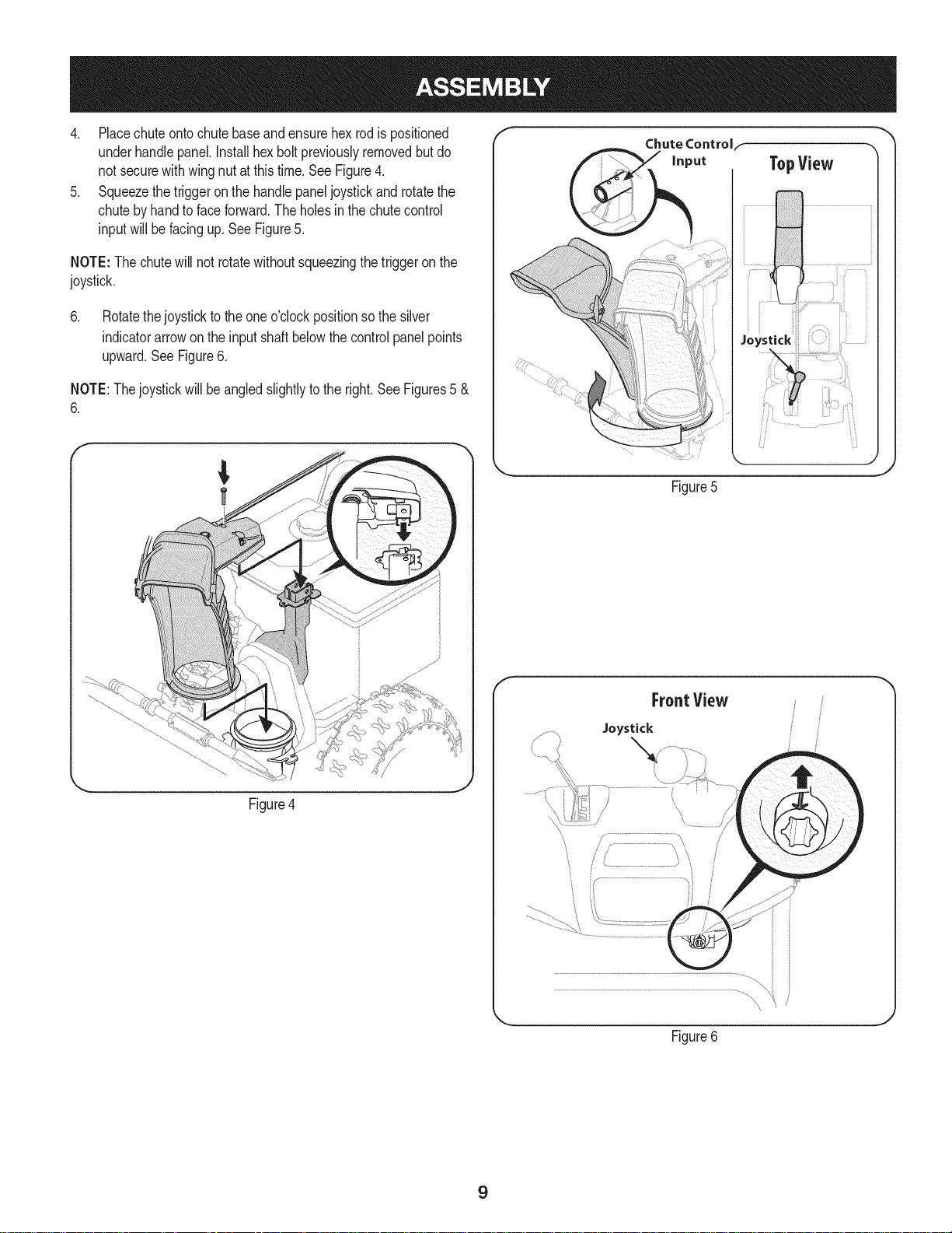
4. Placechuteontochutebaseandensurehexrodis positioned
underhandlepanel.Installhexboltpreviouslyremovedbutdo
notsecurewithwingnut at thistime.See Figure4.
5. Squeezethetriggeron thehandlepaneljoystickandrotatethe
chutebyhandtofaceforward.Theholesinthechutecontrol
inputwill befacingup.SeeFigure5.
NOTE:The chutewill not rotatewithoutsqueezingthetriggeronthe
joystick.
6. Rotatethejoystickto the oneo'clockpositionsothesilver
indicatorarrowontheinputshaft belowthecontrolpanelpoints
upward.SeeFigure6.
NOTE:Thejoystickwillbe angledslightlyto the right.SeeFigures5 &
6.
f
Chute Controlf
TopView
_i¸ ............... t_i
Figure5
Figure4
f
FrontView
Joystick
J
Figure6
9
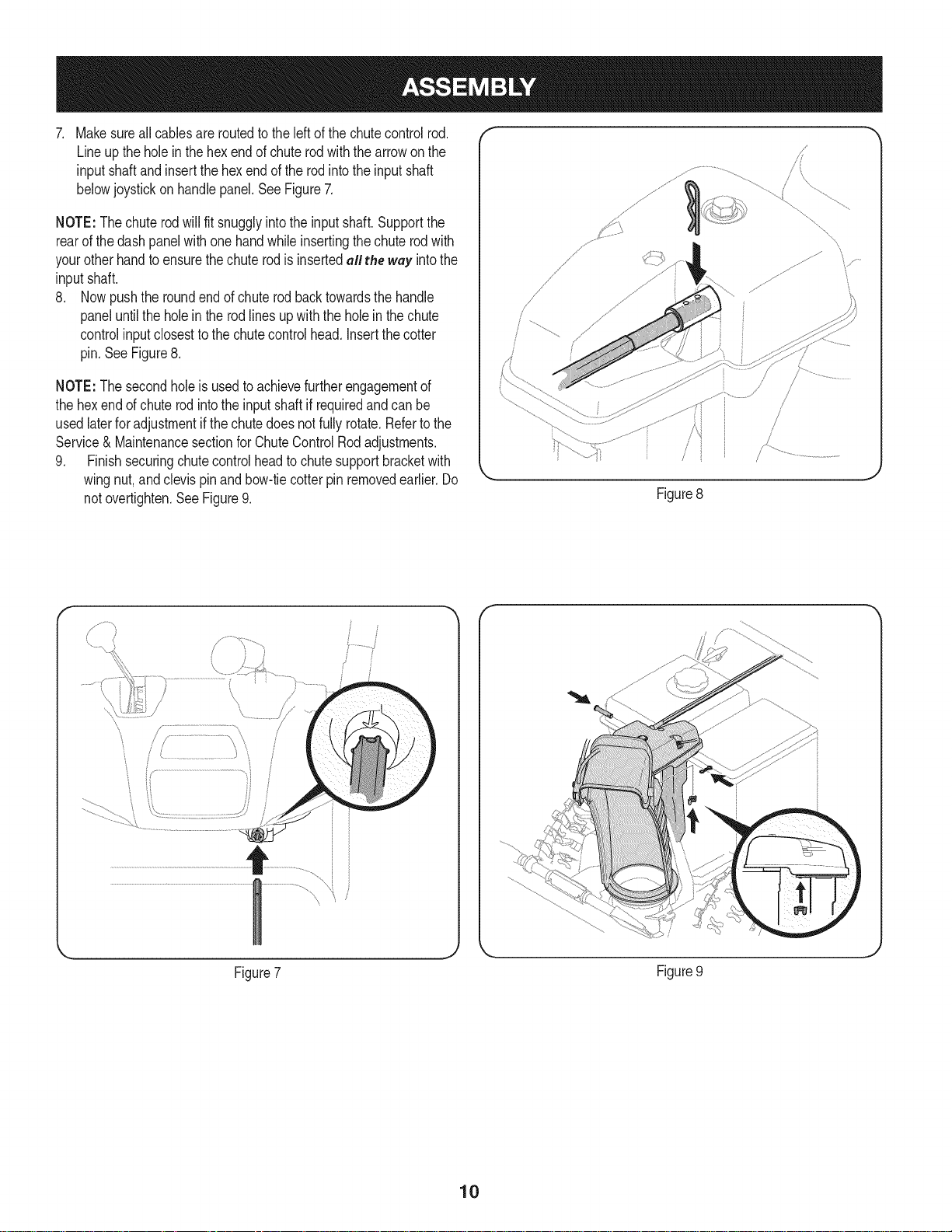
. Makesureallcablesareroutedtotheleft ofthe chutecontrolrod.
Lineuptheholein thehexendofchuterodwiththe arrowonthe
inputshaftandinsertthe hex endof the rodintothe input shaft
belowjoystickon handlepanel.SeeFigure7.
NOTE:Thechuterodwill fit snugglyintotheinputshaft.Supportthe
rearofthedashpanelwithonehandwhileinsertingthechuterodwith
yourotherhandto ensurethechuterodis insertedall the way intothe
inputshaft.
8. Nowpushthe roundend ofchuterod backtowardsthehandle
paneluntilthe holein therodlinesupwiththe holeinthechute
controlinputclosestto the chutecontrolhead. Insertthecotter
pin.SeeFigure8.
NOTE:The secondholeis usedtoachievefurtherengagementof
thehexendofchuterodintotheinputshaft if requiredandcan be
usedlaterforadjustmentif thechutedoesnotfullyrotate.Refertothe
Service& Maintenancesectionfor ChuteControlRodadjustments.
9. Finishsecuringchutecontrolheadtochutesupportbracketwith
wingnut,andclevispinandbow-tiecotterpinremovedearlier.Do
notovertighten.SeeFigure9.
/i _
.J
Figure8
y..................
\,
\
Figure7
Figure9
10
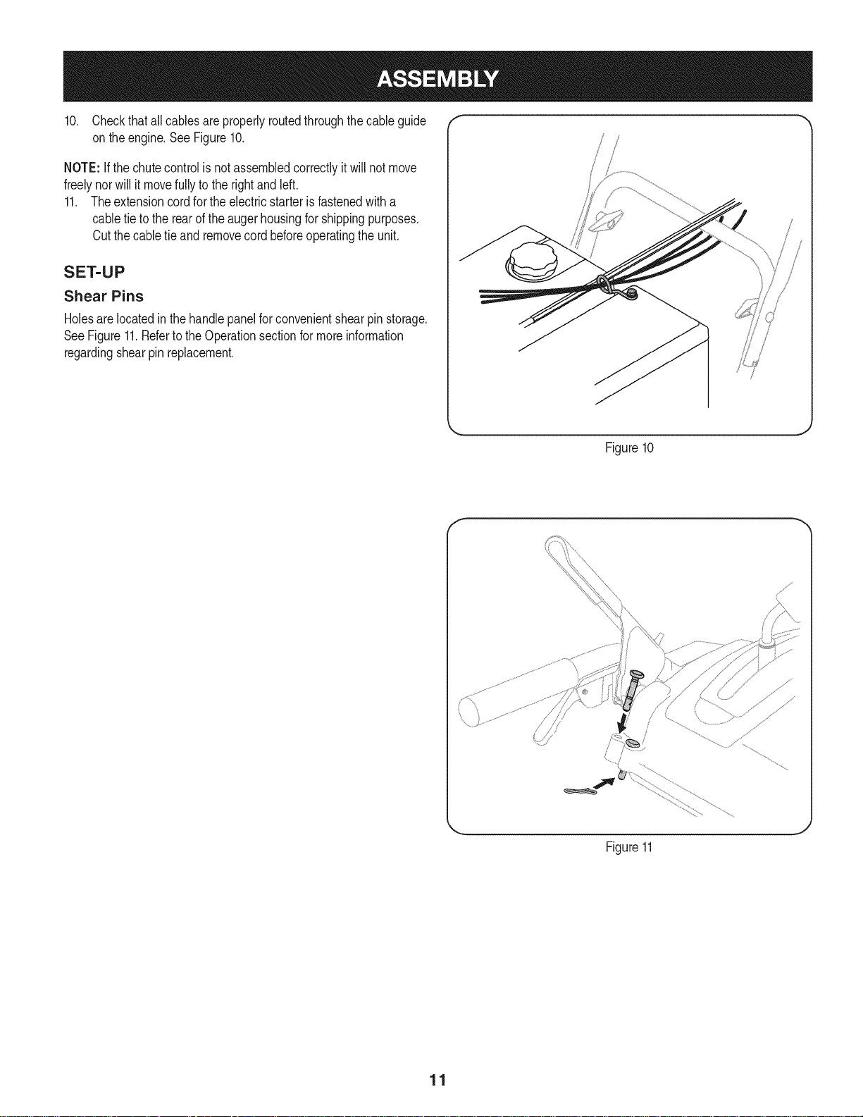
10. Checkthatallcablesareproperlyroutedthroughthecableguide "_
on theengine.SeeFigure10.
NOTE:ifthechutecontrolisnotassembledcorrectlyitwillnotmove
freelynorwillit movefullyto the rightandleft.
11. Theextensioncordforthe electricstarterisfastenedwitha
cabletie to therearoftheaugerhousingforshippingpurposes.
Cutthecabletieand removecordbeforeoperatingthe unit.
SET-UP
Shear Pins
Holesare locatedinthe handlepanelfor convenientshearpin storage.
SeeFigure11.RefertotheOperationsectionformoreinformation
regardingshearpin replacement.
f
Figure10
11
J
Figure11
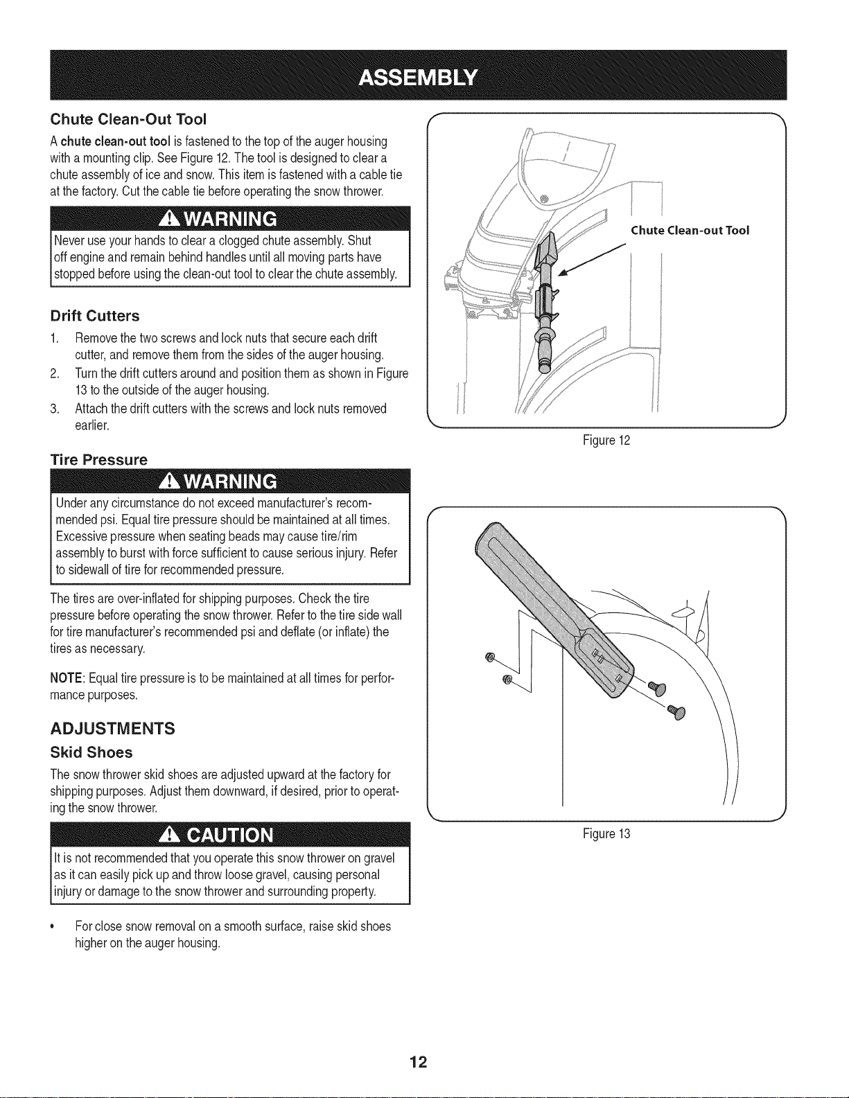
Chute Clean-Out Tool
Achute clean-out tool isfastenedtothe top of the augerhousing
witha mountingclip.SeeFigure12.Thetoolisdesignedtocleara
chuteassemblyofice andsnow.Thisitemisfastenedwitha cabletie
atthefactory.Cutthecabletiebeforeoperatingthesnowthrower.
loft _1 .allmovingpartshave
stoppedbeforeusingtheclean-outtooltoclearthechuteassembly.
Drift Cutters
1. Removethetwo screwsandlocknutsthatsecureeachdrift
cutter,andremovethemfromthesidesoftheaugerhousing.
2. Turnthedriftcuttersaroundandpositionthemas showninFigure
13totheoutsideoftheaugerhousing.
3. Attachthedrift cutterswiththescrewsandlocknutsremoved
earlier.
Tire Pressure
Underanycircumstancedo notexceedmanufacturer'srecom-
mendedpsi.Equaltirepressureshouldbemaintainedatall times.
Excessivepressurewhenseatingbeadsmaycausetire/rim
assemblytoburstwithforcesufficienttocauseseriousinjury.Refer
tosidewallof tirefor recommendedpressure.
Chutedean-out Tool
Figure12
Thetiresareover-inflatedforshippingpurposes.Checkthetire
pressurebeforeoperatingthe snowthrower.Refertothetiresidewall
fortiremanufacturer'srecommendedpsianddeflate(or inflate)the
tiresasnecessary.
NOTE:Equaltire pressureistobe maintainedat alltimesfor perfor-
mancepurposes.
ADJUSTMENTS
Skid Shoes
Thesnowthrowerskidshoesareadjustedupwardatthefactoryfor
shippingpurposes.Adjustthemdownward,ifdesired,priortooperat-
ingthesnowthrower.
It isnotrecommendedthatyouoperatethissnowthrowerongravel
asitcan easilypickup andthrowloosegravel,causingpersonal
njuryordamageto the snowthrowerandsurroundng property.
• Forclosesnowremovalona smoothsurface,raiseskidshoes
higherontheaugerhousing.
Figure13
12
Usea middleorlowerpositionwhentheareato be clearedis
uneven,suchas a graveldriveway.
NOTE:Ifyouchoosetooperatethesnowthroweron agravelsurface,
keepthe skidshoesin positionformaximumclearancebetweenthe
groundandtheshaveplate.
Operatinga snowthrowerequippedwith steelskidshoesmayresult
indamageto naturalstonepaversurfaces(e.g.sandstone,blue-
stone,limestone).Forinformationonavailablepolymerskidshoes,
call1-800-4MY-HOME.
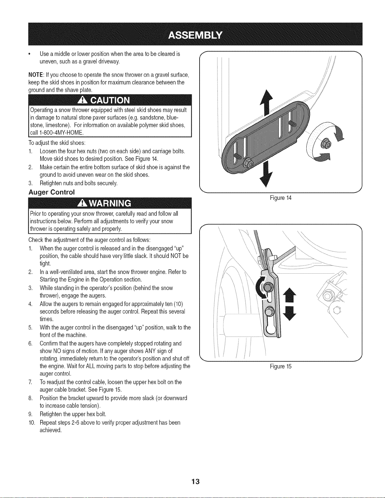
Toadjustthe skidshoes:
1. Loosenthefourhexnuts(twooneach side)andcarriagebolts.
Moveskidshoestodesiredposition.See Figure14.
2. Makecertaintheentirebottomsurfaceof skidshoeis againstthe
groundtoavoidunevenwearonthe skidshoes.
3. Retightennutsandboltssecurely.
Auger Control
Priortooperatingyoursnowthrower,carefullyreadand followall
instructionsbelow.Performalladjustmentstoverifyyoursnow
throwerisoperatingsafelyand properly.
J
Figure14
f
Checktheadjustmentof the augercontrolasfollows:
1. Whentheaugercontrolis releasedandin thedisengaged"up"
position,thecableshouldhaveverylittleslack.ItshouldNOTbe
tight.
2. Ina well-ventilatedarea,startthesnowthrowerengine.Referto
StartingtheEngineintheOperationsection.
3. Whilestandingintheoperator'sposition(behindthe snow
thrower),engagethe augers.
4. Allowtheaugersto remainengagedforapproximatelyten (10)
secondsbeforereleasingthe augercontrol.Repeatthisseveral
times.
5. Withtheaugercontrolin thedisengaged"up"position,walktothe
frontofthemachine.
6. Confirmthatthe augershavecompletelystoppedrotatingand
showNOsignsof motion.IfanyaugershowsANYsignof
rotating,immediatelyreturntothe operator'spositionandshutoff
theengine.WaitforALLmovingpartsto stopbeforeadjustingthe
augercontrol.
7. Toreadjustthecontrolcable,loosentheupperhexbolt onthe
augercablebracket.SeeFigure15.
8. Positionthe bracketupwardtoprovidemoreslack(or downward
toincreasecabletension).
9. Retightentheupperhex bolt.
10. Repeatsteps2-6aboveto verifyproperadjustmenthasbeen
achieved.
f
/
J
Figure15
13
f
Drive Control
Headlight
GasCap
Shift Lever
F Four-Way Chute ControP (Joystick)
F
F
Auger Control
Heated Grip
Chute Assembly
Drift Cutter
Augers
\
\
\
Skid Shoe
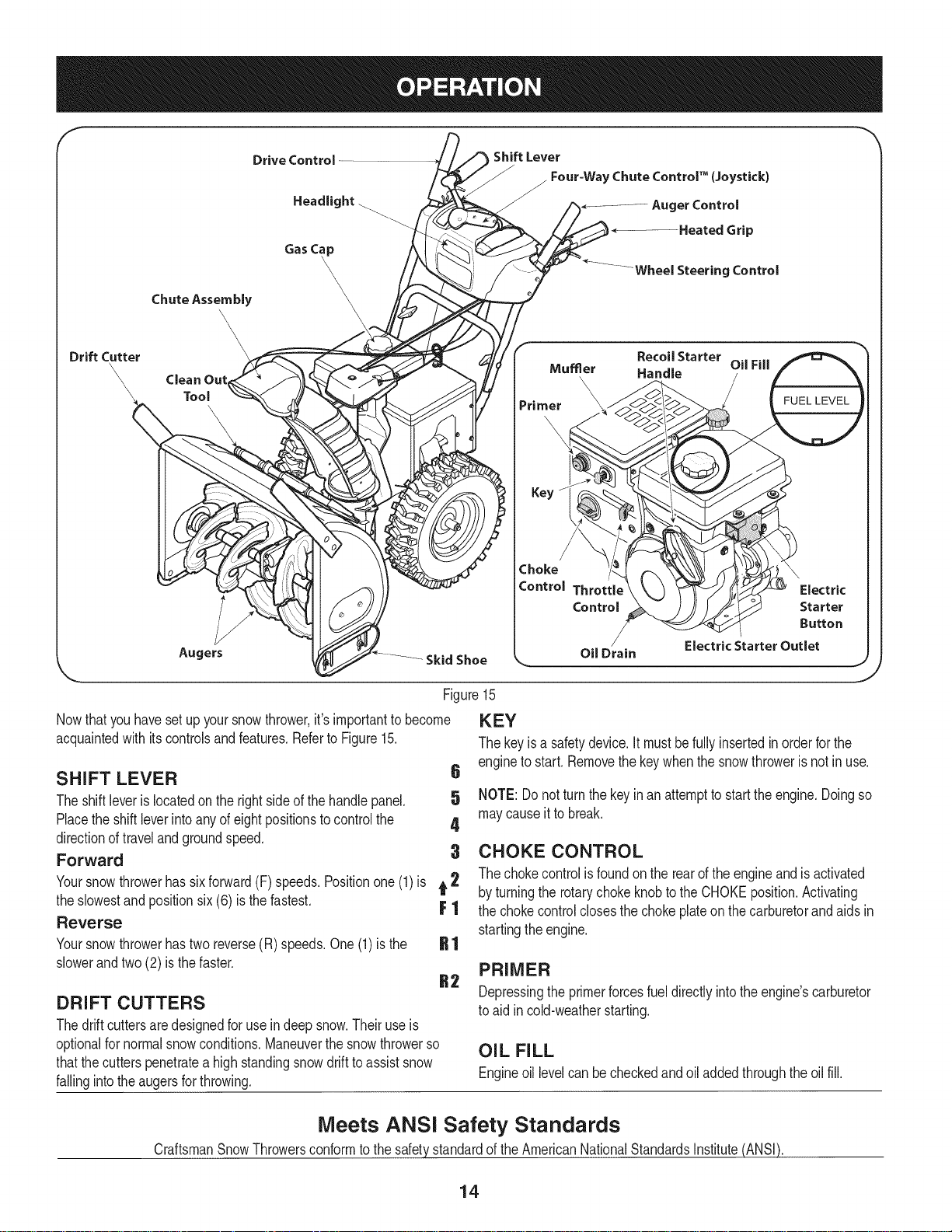
Figure15
Nowthat youhavesetup yoursnowthrower,it'simportanttobecome
acquaintedwith itscontrolsandfeatures.Referto Figure15.
SHIFT LEVER 6
Theshiftleverislocatedonthe rightsideofthe handlepanel. 5
Placethe shiftleverinto anyofeightpositionstocontrolthe 4
directionoftravelandgroundspeed.
Forward 3
Yoursnowthrowerhassixforward(F)speeds.Positionone(1)is t 2
theslowestand positionsix (6) is the fastest. F 1
Reverse
Yoursnowthrowerhastwo reverse(R) speeds.One(1)is the
slowerandtwo(2) isthefaster.
DRIFT CUTTERS
Thedrift cuttersaredesignedforuse indeepsnow.Theiruseis
optionalfornormalsnowconditions.Maneuverthe snowthrowerso
thatthecutterspenetratea highstandingsnowdrifttoassistsnow
fallingintotheaugersforthrowing.
Mumer
Primer
Recoil Starter
\
\
Handle
Oil Fill
FUEL LEVEL
\
Key
Choke
Control Throttle
Control
/
OilDrain
Electric StarterOutlet
KEY
Thekeyisa safetydevice.It mustbefullyinsertedinorderfor the
engineto start.Removethekeywhenthesnowthroweris not inuse.
NOTE:Donot turnthekeyinan attempttostarttheengine.Doingso
maycauseit tobreak.
CHOKE CONTROL
Thechokecontrolisfoundon therearoftheengineand is activated
byturningthe rotarychokeknobtotheCHOKEposition.Activating
thechokecontrolclosesthe chokeplateon thecarburetorandaidsin
startingthe engine.
PRIMER
Depressingthe primerforcesfueldirectlyintotheengine'scarburetor
toaid incold-weatherstarting.
OIL FILL
Engineoil levelcan becheckedandoiladdedthroughtheoil fill.
\
Electric
Starter
Button
Meets ANSI Safety Standards
CraftsmanSnowThrowersconformto the safetystandardoftheAmericanNationalStandardsInstitute(ANSI).
14

THROTTLE CONTROL
Thethrottlecontrolis locatedonthe rearof the engine.It regulatesthe
speedof theengineandwill shutoff theenginewhenmovedintothe
STOPposition.
ELECTRIC STARTER BUTTON
Pressingtheelectricstarterbuttonengagestheengine'selectric
starterwhenpluggedintoa 120Vpowersource.
ELECTRIC STARTER OUTLET
Requirestheuseof athree-prongoutdoorextensioncord(included)
anda 120Vpowersource/walloutlet.
AUGERS
Whenengaged,theaugerbladesrotateand drawsnowintotheauger
housing.
SKID SHOES
Positiontheskid shoesbasedonsurfaceconditions.Adjustupward
forhard-packedsnow.Adjustdownwardwhenoperatingongravelor
crushedrocksurfaces.
HEADLIGHT
Theheadlightison whenevertheengineisrunning.
HEATED GRIPS
Toactivatethe heatedgrips,movetheswitchfoundon therearof the
dashpanelintotheONposition.
WHEEL STEERING CONTROLS
Theleft andrightwheelsteeringcontrolsarelocatedon theunderside
ofthehandles.Squeezethe rightcontroltoturnright;squeezethe left
controltoturn left.
NOTE:Operatethesnowthrowerinopenareasuntilyou arefamiliar
withthesecontrols.
Theaugercontrolislocatedon thelefthandle.Squeezethe control
gripagainstthehandletoengagetheaugerand startsnowthrowing
action.Releaseto stop.
DRIVE CONTROL/AUGER CONTROL LOCK
DRIVE
CONTROL
Thedrivecontrolis locatedon the righthandle.Squeezethecontrol
gripagainstthehandletoengagethewheeldrive.Releasetostop.
Thedrivecontrolalso lockstheaugercontrolsoyoucan operate
thechutedirectionalcontrolwithoutinterruptingthesnowthrowing
process.If theaugercontrolis engagedsimultaneouslywiththedrive
control,the operatorcanreleasetheaugercontrol(onthelefthandle)
andtheaugerswill remainengaged.Releasebothcontrolstostopthe
augersandwheeldrive.
NOTE:Alwaysreleasethedrivecontrolbeforechangingspeeds.
Failureto dosowill resultinincreasedwearon yourmachine'sdrive
system.
FOUR=WAY CHUTE CONTROL TM
CHUTE DiRECTiONAL CONTROL
CHUTETiLTDOWN
t
CHUTEROTATE CHUTEROTATE
LEFT RIGHT
AUGER CONTROL
CHUTETiLTUP
Thefour-waychutecontrolTM (Joystick)islocatedon theleft sideof the
handlepanel.
* Tochangethedirectioninwhichsnowisthrown,squeezethe
buttononthechutecontrolleverandpivotthechutecontrollever
tothe rightortotheleft.
* Tochangetheangle/distancewhichsnowisthrown,pivotthe
chutecontrolleverforwardto tiltthechutedownandbackwardto
tilt the chuteup.
15
j,
CLEAN-OUT TOOL
Neveruseyourhandsto cleara cloggedchuteassembly.Shut
loft engineandremainbehindhandlesuntilallmovingpartshave
lstoppedbeforeusingtheclean-outtoolto clearthechuteassembly.
Thechuteclean-outtoolisconvenientlyfastenedtothe rearof the
augerhousingwitha mountingclip. Shouldsnowandicebecome
lodgedin thechuteassemblyduringoperation,proceedasfollowsto
safelycleanthechuteassemblyandchuteopening:
1. Releaseboththe AugerControlandtheDriveControl.
2. Stopthe engineby removingtheignitionkey.
3. Removetheclean-outtoolfromthe clip whichsecuresittothe
rearoftheaugerhousing.
4. Usetheshovel-shapedendof theclean-outtoolto dislodgeand
scoopanysnowand icewhichhasformedinandnearthechute
assembly.
5. Refastenthe clean-outtooltothemountingcliponthe rearof
theaugerhousing,reinserttheignitionkeyandstartthesnow
thrower'sengine.
6. Whilestandingintheoperator'sposition(behindthesnow
thrower),engagethe augercontrolfora fewsecondstoclearany
remainingsnowandice fromthechuteassembly.
BEFORE STARTING ENGINE
Read,understand,andfollowall instructionsandwarningson the
machineand inthismanualbeforeoperating.
Oil
Theunit wasshippedwith oil inthe engine.Checkoillevelbefore
eachoperationtoensureadequateoilintheengine.Forfurther
instructions,refertothe stepson page18.
NOTE:Besureto checktheengineon a levelsurfacewiththeengine
stopped.
1. Removetheoil fillercap/dipstickandwipethedipstickclean.
2. insertthecap/dipstickintotheoilfiller neck,andtightenthecap
untilseated.
3. Removetheoil fillercap/dipstick,ifthelevelislow,slowlyadd
oil (5%30, witha minimumclassificationof SF/SG)untiloil level
registersbetweenhigh(H) andlow(L).
NOTE:Do notoverfill.Overfillingwithoil mayresultinenginesmoking,
hardstartingorsparkplugfouling.
4. Replaceandtightencap/dipstickfirmlybeforestartingengine.
Gasoline
Useautomotivegasoline(unleadedor lowleadedtominimizecombus-
tionchamberdeposits)witha minimumof87octane.Gasolinewith
upto 10%ethanolor 15%MTBE(MethylTertiaryButylEther)canbe
used.Neveruseanoil/gasolinemixtureordirtygasoline.Avoidgetting
dirt,dust,or waterinthefueltank.DONOTuseE85gasoline.
• Refuelina well-ventilatedareawiththeenginestopped.Donot
smokeorallowflamesor sparksinthe areawheretheengineis
refueledor wheregasolineisstored.
• Donot overfillthe fueltank.After refueling,makesurethetank
capisclosedproperlyandsecurely.
• Becarefulnotto spillfuelwhenrefueling.Spilledfuelorfuel vapor
mayignite,ifany fuelisspilled,makesurethe areaisdry before
startingthe engine.
• Avoidrepeatedorprolongedcontactwithskinor breathingof
)or.
Useextremecarewhenhandlinggasoline.Gasolineisextremely
flammableandthevaporsare explosive.Neverfuelthemachine
indoorsorwhiletheengineis hotor running.Extinguishcigarettes,
cigars,pipesandothersourcesof ignition.
1. Cleanaroundfuelfill beforeremovingcaptofuel.
2. A fuellevelindicatorislocatedin thefueltank.SeeFigure15
inset.Becarefulnotto overfill.Filltank untilfuelreachesthe fuel
levelindicatortoallowspaceforfuel expansion.
STARTING THE ENGINE
Alwayskeephandsandfeetclearof movingparts.Donot usea
pressurizedstartingfluid.Vaporsareflammable.
NOTE:Allowtheenginetowarmupfor a fewminutesafter starting.
Theenginewillnotdevelopfullpoweruntilit reachesoperating
temperatures.
1. Makecertainboththe augercontrolanddrivecontrolarein the
disengaged(released)position.
2. insertkeyintoslot.Makesureit snapsintoplace.Donotattempt
toturnthekey.
NOTE:Theenginecannotstartwithoutthekeyfullyinsertedintothe
ignitionswitch.
Electric Starter
Theoptionalelectricstarteris equippedwitha groundedthree-wire
powercordandplug,and is designedto operateon 120voltAC
householdcurrent.It mustbeusedwitha properlygroundedthree-
prongreceptacleatall timestoavoidthe possibilityofelectricshock.
Followall instructionscarefullypriortooperatingtheelectricstarter.
DONOTuse electricstarterintherain.
Determinethatyourhome'swiringisa three-wiregroundedsystem.
Aska licensedelectricianifyouarenotcertain.
Ifyouhaveagroundedthree-prongreceptacle,proceedasfollows.
Ifyoudonothavetheproperhousewiring,DONOTusetheelectric
starterunderanyconditions.
1. Plugtheextensioncord intotheoutletlocatedonthe engine's
surface.Plugtheotherendof extensioncordintoa three-prong
120-volt,grounded,ACoutletina well-ventilatedarea.
16

2. Movethrottlecontrolto FAST(rabbit)'_ position.
3. MovechoketotheCHOKEIJl position(coldenginestart).If
engineiswarm,placechokein RUNposition.
4. Pushprimerthree(3)times,makingsuretocoverventholein
primerbulbwhen pushing.Ifengineis warm,pushprimeronly
once.Alwayscoverventholewhenpushing.Coolweathermay
requireprimingtobe repeated.
5. Pushstarterbuttontostartengine.Oncetheenginestarts,im-
mediatelyreleasestarterbutton.Electricstarteris equippedwith
thermaloverloadprotection;systemwilltemporarilyshut-downto
allowstartertocoolifelectricstarterbecomesoverloaded.
6. Astheenginewarms,slowlyrotatethechokecontrolto RUN
position.Ifthe enginefalters,restartengineandrunwithchoke
athalf-chokepositionfor a shortperiodoftime,andthenslowly
rotatethechokeinto RUNposition.
7. Afterengineisrunning,disconnectpowercordfromelectric
starter.Whendisconnecting,alwaysunplugtheendatthewall
outletbeforeunpluggingtheoppositeendfromtheengine.
Recoil Starter
Donotpullthestarterhandlewhiletheenginerunning.
1. Movethrottlecontrolto FAST(rabbit)'_ position.
2. MovechoketotheCHOKEI,'_1 position(coldenginestart).If
engineiswarm,placechokein RUNposition.
3. Pushprimerthree(3)times,makingsuretocoverventholewhen
pushing.Ifengineiswarm,push primeronlyonce.Alwayscover
ventholewhenpushing.Coolweathermayrequireprimingtobe
repeated.
4. Pullgentlyonthe starterhandleuntil it beginstoresist,then
pullquicklyandforcefullytoovercomethecompression.Engine
shouldstart.Donotreleasethehandleandallow it to snapback.
ReturnropeSLOWLYtooriginalposition.If required,repeatthis
step.
5. Astheenginewarms,slowlyrotatethechokecontrolto RUN
position.Ifthe enginefalters,restartengineandrunwithchoke
athalf-chokepositionfor a shortperiodoftime,andthenslowly
rotatethechokeinto RUNposition.
TO ENGAGE DRIVE
1. Withthe throttlecontrolinthe Fast(rabbit)position,moveshift
leverintooneofthesixforward(F) positionsor tworeverse(R)
positions.Selecta speedappropriateforthesnowconditionsand
a paceyou'recomfortablewith.
NOTE:Whenselectinga DriveSpeed,usetheslowerspeedsuntil
youarecomfortableandfamiliarwiththe operationofthesnow
thrower.
2. Squeezethedrivecontrolagainstthehandleandthesnow
throwerwillmove.Releaseitanddrive motionwillstop.
NOTE:NEVERrepositionthe shiftlever(changespeedsordirection
oftravel)withoutfirst releasingthedrivecontrolandbringingthe snow
throwertoa completestop.Doingsowill resultinprematurewearto
thesnowthrower'sdrivesystem.
TO ENGAGE AUGER
1. Toengagetheaugerand startthrowingsnow,squeezethe auger
controlagainsttheleft handle.Releasetostopthe auger.
REPLACING SHEAR PiNS
Theaugersaresecuredtothespiralshaftwith shearpinsandcotter
pins.If the augersshouldstrikeaforeignobjectoricejam,the snow
throwerisdesignedsothatthepinsmayshear.If theaugerswillnot
turn,checkto see if thepins havesheared.SeeFigure16.
NEVERreplacetheaugershearpinswithanythingotherthan Sears
SKU#88389/0EM PartNo.738-04124Areplacementshearpins.
Anydamagetotheaugergearboxorother componentsas a resultof
failingto do sowill NOTbecoveredbyyoursnowthrower'swarranty.
Alwaysturnoff thesnowthrower'sengineand removethe keypriorto
replacingshearpins.
if -,
Toavoidunsupervisedengineoperation,neverleavethemachine
unattendedwiththeenginerunning.Turnthe engineoffafter useand
removekey.
STOPPING THE ENGINE
Afteryouhavefinishedsnow-throwing,runenginefora few minutes
beforestoppingtohelpdryoffany moistureontheengine.
1. MovethrottlecontroltoOFFposition.
2. Removethekey.Removingthe keywill reducethepossibilityof
unauthorizedstartingoftheenginewhileequipmentis notin use.
Keepthekeyina safeplace.Theenginecannotstartwithoutthe
key.
3. Wipeanymoistureawayfromthe controlson theengine.
Figure16
17
MAINTENANCE SCHEDULE
Beforeperforminganytypeofmaintenance/service,disengageall
controlsandstoptheengine.Waituntilallmovingpartshavecometo
acompletestop.Disconnectsparkplugwireandgrounditagainstthe
enginetopreventunintendedstarting.Alwayswearsafetyglassesduring
operationorwhileperforminganyadjustmentsorrepairs.
EachUseandevery5
hours
1st5 hours
Annuallyor25 hours
Annuallyor50 hours
Annuallyor100hours
BeforeStorage
1. Engineoil level
2. Looseormissinghardware
3. Unitandengine.
1. Engineoil
1. Sparkplug
2. Controllinkagesandpivots
3. Wheels
4. GearshaftandAugershaft
1. Engineoil
1. Sparkplug
1. Fuelsystem
1. Check
2. Tightenor replace
3. Clean
1. Change
1. Check
2. Lubewithlightoil
3. Lubewithmultipurposeautogrease
4. Lubewithlightoil
1. Change
1. Change
1. Runengineuntilit stopsfromlack
ENGINE MAINTENANCE
Checking Engine Oil
Followthemaintenanceschedulegivenbelow.Thischartdescribes
serviceguidelinesonly.Usethe ServiceLogcolumnto keeptrackof
completedmaintenancetasks.Tolocate the nearest SearsService
Centeror to scheduleservice,simplycontactSearsat
1-800-4-MY-HOME®.
d fuel
Beforelubricating,repairing,or inspecting,disengageall controls
Iandstopengine.Waituntilall movingpartshavecometo acomplete
_stop.
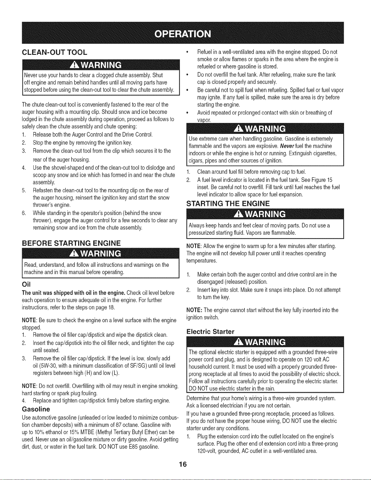
NOTE: Checktheoil levelbeforeeachuseto besurecorrectoil level
ismaintained.
Whenaddingoilto the engine,referto viscositychart below.Engine
oilcapacityis 1100ml(approx.37oz.).Donotover-fill.Usea 4-stroke,
oran equivalenthighdetergent,premiumqualitymotoroilcertified
tomeetorexceedU.S.automobilemanufacturer'srequirementsfor
serviceclassificationSG, SR MotoroilsclassifiedSG,SFwillshow
thisdesignationonthe container.
1. Removetheoil fillercap/dipstickandwipethedipstickclean.
2. Insertthe cap/dipstickintothe oilfiller neck,andtightenthe cap
untilseated.
3. Removetheoil fillercap/dipstick.Iflevelislow,slowlyaddoiluntil
oil levelregistersbetweenhigh(H)andlow(L).SeeFigure17.
4. Replaceandtightencap/dipstickfirmlybeforestartingengine.
Changing Engine Oil
NOTE:Changetheengineoilafterthefirst5 hoursof operationand
oncea seasonorevery50 hoursthereafter.
1. Drainfuelfromtankbyrunningengineuntilthe fuel tankisempty.
Besurefuel fill capis secure.
J
Figure17
2. Placesuitableoil collectioncontainerunderoil drainplug.
3. Removeoil drainplug.SeeFigure18on nextpage.
4. Tipenginetodrainoil intothe container.Usedoil mustbe
disposedofat a propercollectioncenter.
Usedoil isa hazardouswasteproduct.Disposeofusedoil properly.
IDo notdiscardwithhouseholdwaste.Checkwithyourlocalauthori-
lties or SearsServiceCenterforsafedisposal/recyclingfacilities.
18

.
Reinstallthedrainplugandtightenit securely.
6.
Refillwiththerecommendedoilandchecktheoil level.See
RecommendedOil Usagechart.Theengine'soil capacityis37
ounces.
, ,
[
(%-40 °-20 o 0o 200 400
("c) -300 -200 -10° 0°
DONOTusenondetergentoilor 2-strokeengineoil.Itcouldshorten
theengine'sservicelife.
Oil Drain
Plug
7. Reinstalltheoilfillercap/dipsticksecurely.
Thoroughlywashyourhandswithsoapandwaterassoonas
possibleafterhandling usedoil.
Checking Spark Plug
DONOTcheckfor sparkwithsparkplugremoved.DONOTcrank
enginewithsparkplug removed.
Iftheenginehasbeenrunning,themufflerwillbevery hot.Becareful
notto touchthe muffler.
NOTE: Checkthesparkplugoncea seasonorevery25hoursof
operation.Changethesparkplugoncea seasonor every100hours.
Toensureproperengineoperation,thesparkplugmustbe properly
gappedandfreeof deposits.
1. Removethesparkplugbootanduse a sparkplugwrenchto
removetheplug.See Figure19.
2. Visuallyinspectthesparkplug.Discardthesparkplugifthereis
apparentwear,orif the insulatoris crackedor chipped.Cleanthe
sparkplugwitha wirebrush if it is to bereused.
3. Measurethe pluggapwitha feelergauge.Correctas necessary
bybendingsideelectrode.SeeFigure20.Thegap shouldbe set
to.02-.03inches(0.60-0.80ram).
4. Checkthatthe sparkplugwasherisingoodconditionandthread
thesparkplugin byhandto preventcross-threading.
5. Afterthesparkplugisseated,tightenwitha sparkplugwrenchto
compressthewasher.
NOTE:Wheninstallinga newsparkplug,tighten1/2-turnafterthe
sparkplugseatsto compressthewasher.Whenreinstallinga used
sparkplug,tighten1/8-to 1/4-turnafterthesparkplugseatsto
compressthewasher.
19
J
Electrode
Figure18
Spark Plug
O
SparkPlug Boot
Figure19
.02=.03 in.
(0.60-0.80 ram)
Figure20
hotandcan ine.
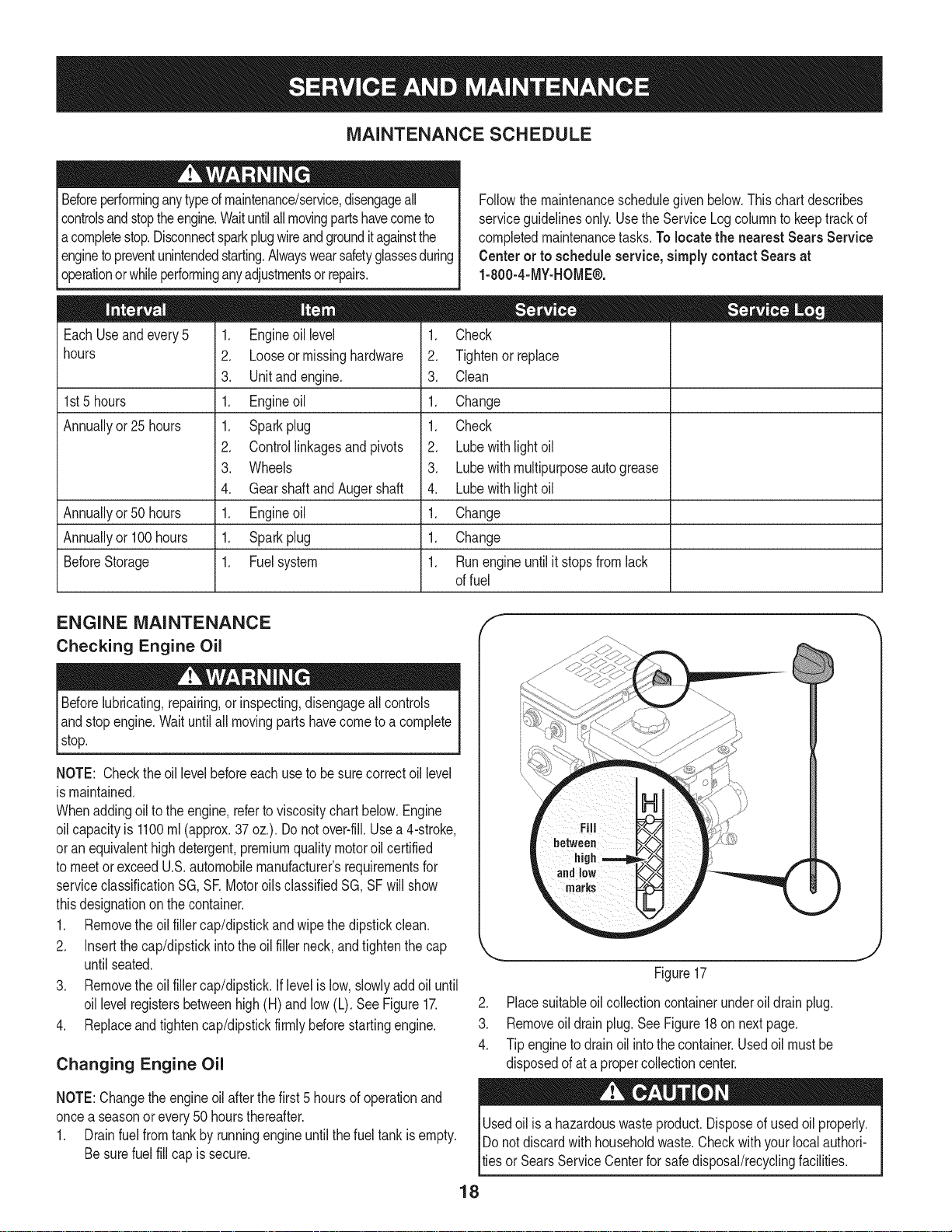
LUBRICATION
Gear Shaft
Thegear(hex)shaftshouldbelubricatedat leastoncea seasonor
afterevery25 hoursofoperation.
1. Topreventspillage,removeall fuelfromtank by runningengine
untilitstops.
2. Carefullypivotthesnowthrowerupandforwardso that itrestson
theaugerhousing.
3. Removethe lowerframecoverfromthe undersideofthesnow
throwerbyremovingtheself-tappingscrewswhichsecureit.
4. Applya lightcoatingofengineoil (or3-in-1oil) to the hexshaft.
SeeFigure21.
/ .... )
{;:7/
7/' ................
)
// "?X
NOTE:Whenlubricatingthehexshaft,be carefulnottogetanyoilon
thealuminumdriveplateor rubberfrictionwheel.Doingsowillhinder
thesnowthrower'sdrivesystem.Wipeoff anyexcessor spilledoil.
Wheels
Atleastoncea season,removebothwheels.Cleanandcoattheaxles
witha multipurposeautomotivegreasebeforereinstallingwheels.
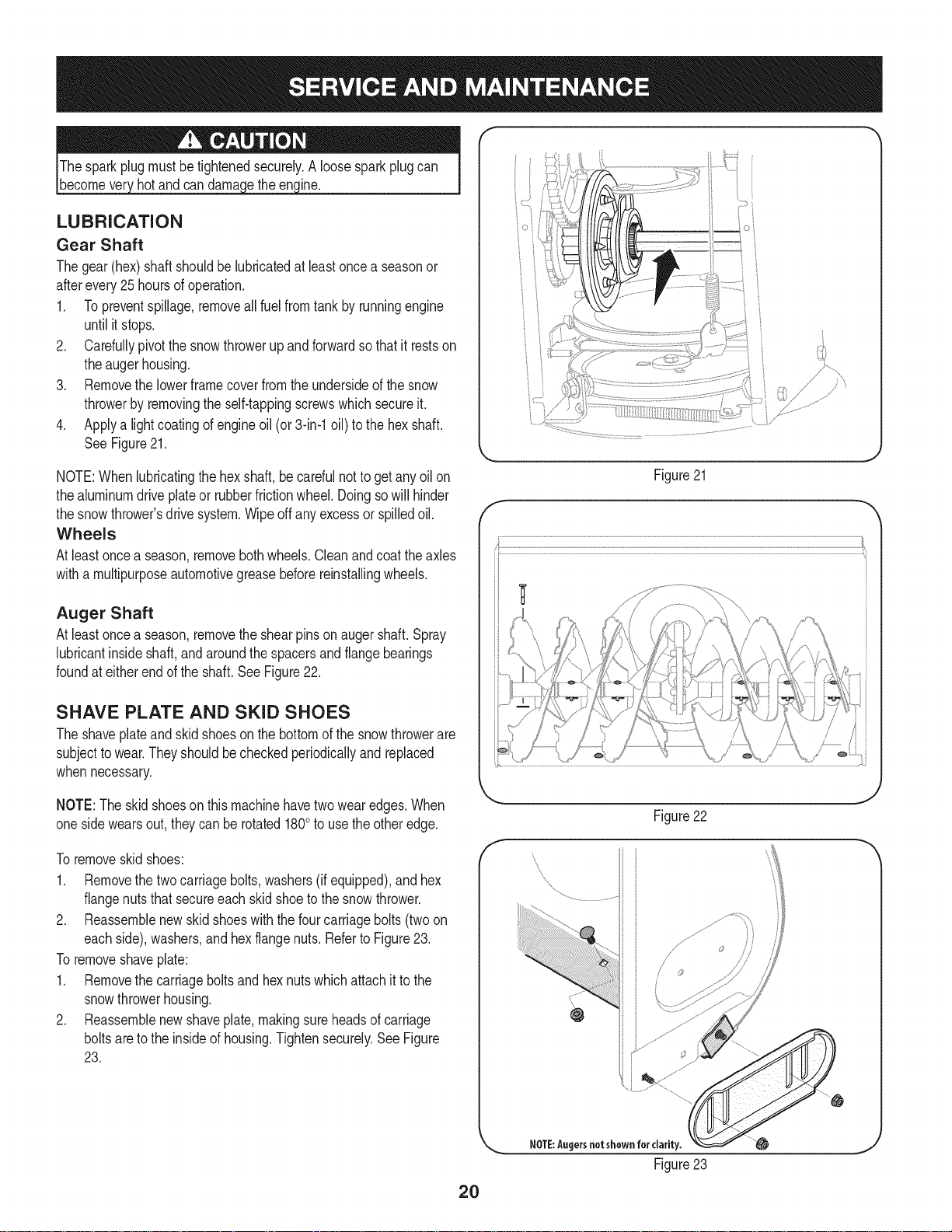
Auger Shaft
Atleastoncea season,removetheshearpinson augershaft.Spray
lubricantinsideshaft,andaroundthe spacersandflangebearings
foundat eitherendoftheshaft.SeeFigure22.
SHAVE PLATE AND SKID SHOES
Theshaveplateandskidshoesonthebottomofthe snowthrowerare
subjecttowear.Theyshouldbecheckedperiodicallyandreplaced
whennecessary.
NOTE:Theskidshoeson thismachinehavetwowearedges.When
onesidewearsout,theycanbe rotated1800to usetheotheredge.
Toremoveskidshoes:
1. Removethetwocarriagebolts,washers(ifequipped),andhex
flangenutsthat secureeach skidshoetothesnowthrower.
2. Reassemblenewskidshoeswiththe fourcarriagebolts(twoon
eachside),washers,andhex flangenuts.RefertoFigure23.
Toremoveshaveplate:
1. Removethecarriageboltsand hexnutswhichattachit to the
snowthrowerhousing.
2. Reassemblenewshaveplate,makingsureheadsofcarriage
boltsaretotheinsideofhousing.Tightensecurely.SeeFigure
23.
Figure21
f
J
Figure22
f
\
\
\
2O
NOTE:Augersnotshown for clarity.
Figure23
ADJUSTMENTS
Shift Cable
If thefull rangeofspeeds(forwardandreverse)cannotbeachieved,
referto the figuretotherightandadjusttheshiftcableas follows:
1. Placetheshiftleverin thefastest forwardspeedposition(F6).
2. Loosenthehex nuton the shiftcableindexbracket.SeeFigure
24.
3. Pivotthebracketdownwardto takeupslackinthe cable.
4. Retightenthehexnut.
Drive Control
Whenthedrivecontrolisreleasedandin thedisengaged"up"position,
thecableshouldhaveverylittle slack.It shouldNOTbetight.Also,
ifthereis excessiveslackin thedrivecableor ifthe unitexperiences
intermittentdrivewhileusing,thecable mayneedtobeadjusted.
Checktheadjustmentof the drivecontrolasfollows:
1. Withthedrivecontrolreleased,pushthesnowthrowergently
forward.Theunitshouldrollfreely.
2. Engagethe drivecontrolandgentlyattemptto pushthesnow
throwerforward.Thewheelsshouldnotturn.Theunitshouldnot
rollfreely.
3. Withthedrivecontrolreleased,movetheshiftleverbackand
forthbetweenthe R2positionandthe F6 positionseveraltimes.
Thereshouldbeno resistancein the shiftlever.
4. If anyoftheabovetestsfailed,thedrivecable is in needofadjust-
ment.Proceedasfollows:
5. Loosenthelowerhexbolt onthe drivecablebracket.SeeFigure
25.
6. Positionthe bracketupwardtoprovidemoreslack(or downward
toincreasecabletension).
7. Retightenthelowerhexboltand repeatsteps1 through4.
J
f
.........
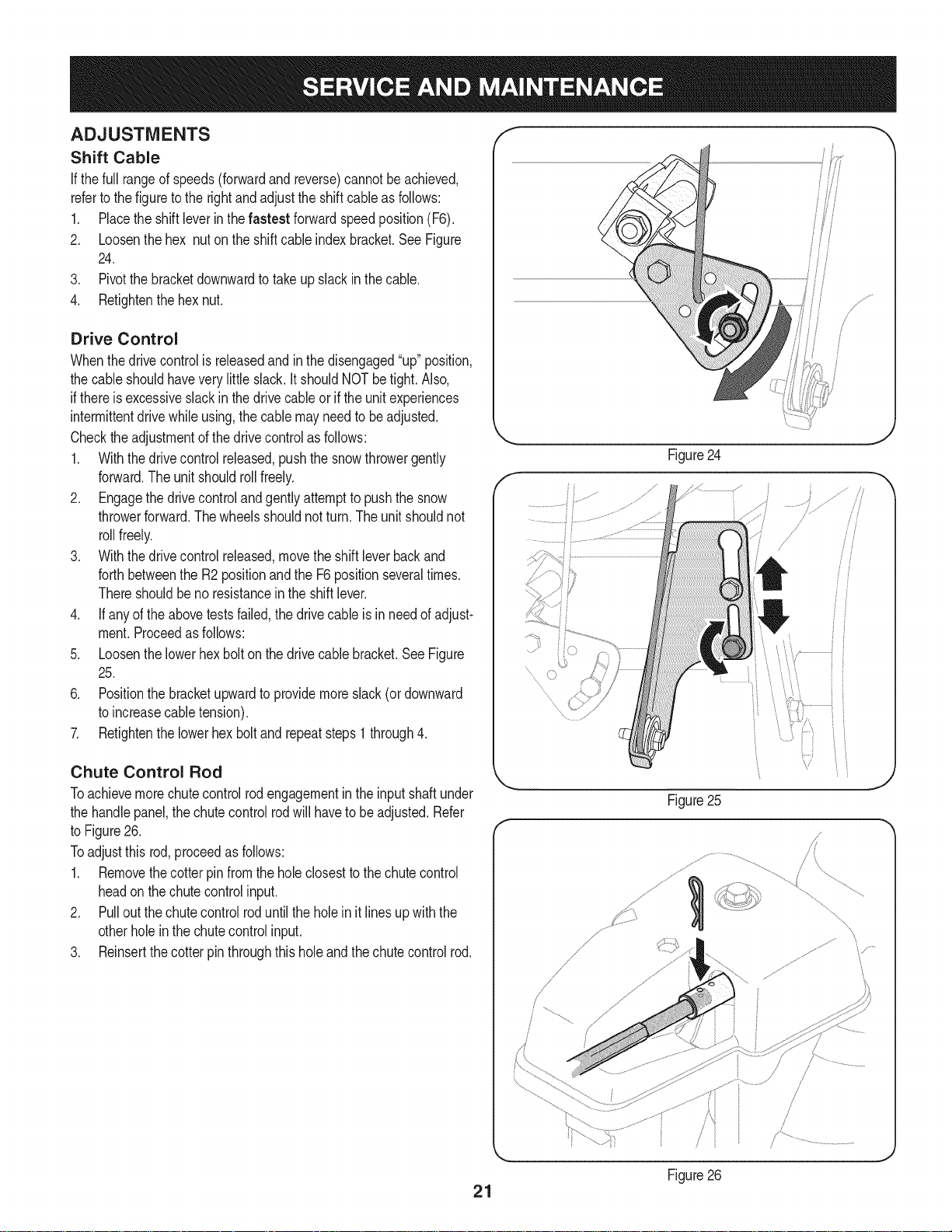
Chute Control Rod
Toachievemorechutecontrolrodengagementintheinputshaftunder
thehandlepanel,thechutecontrolrodwill havetobeadjusted.Refer
toFigure26.
Toadjustthis rod,proceedasfollows:
1. Removethecotterpin fromthe holeclosestto the chutecontrol
headon thechutecontrolinput.
2. Pulloutthechutecontrolroduntilthe holein itlines upwiththe
otherholeinthechutecontrolinput.
3. Reinsertthecotterpinthroughthisholeandthechutecontrolrod.
21
Figure25
/
/ ,
Figure26
J
J
\
\
Auger Control f "_
RefertotheAssemblysectionforinstructionsonadjustingtheauger
controlcable. _'
Skid Shoes
RefertotheAssemblysectionforinstructionsonadjustingtheskid
shoes.
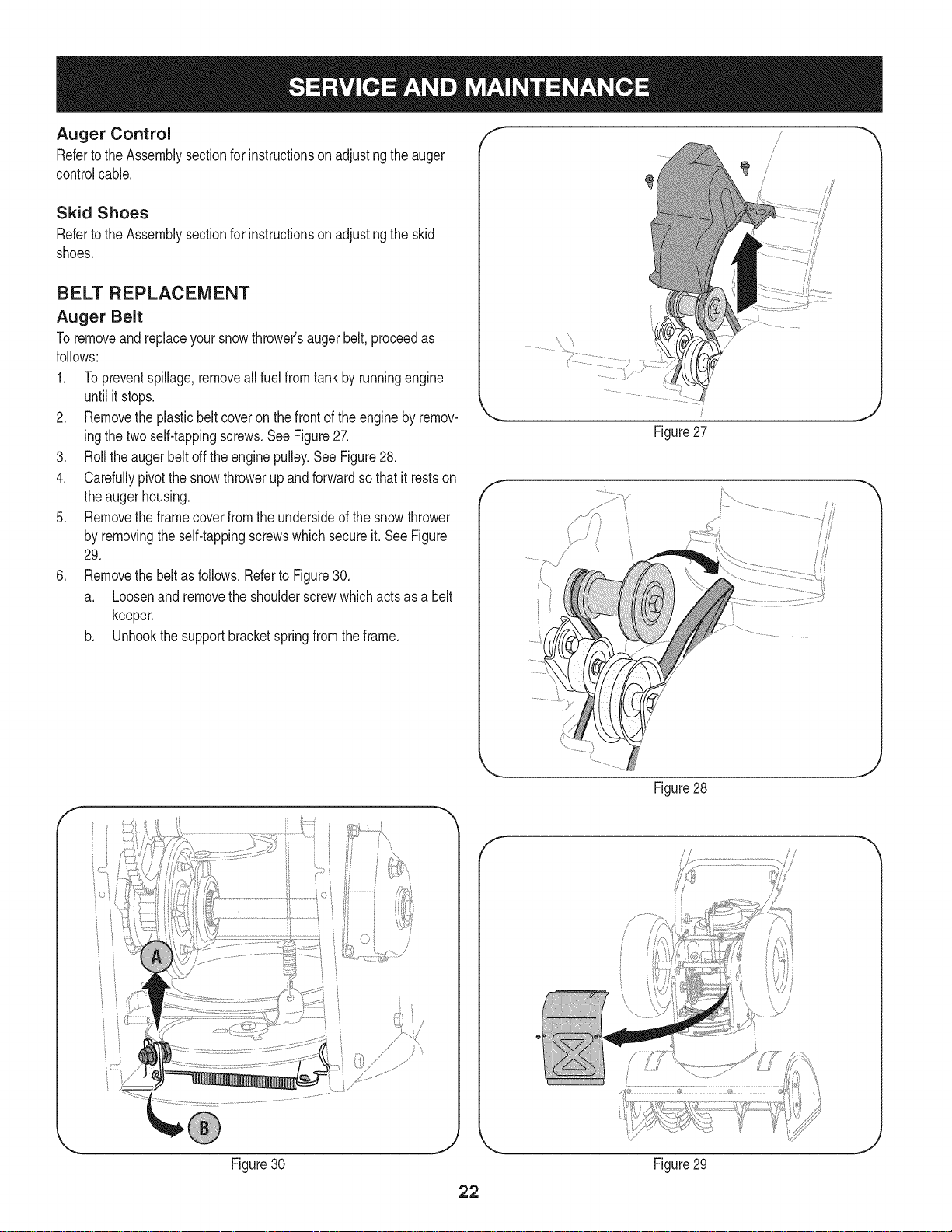
BELT REPLACEMENT
Auger Belt
Toremoveandreplaceyoursnowthrower'saugerbelt,proceedas
follows:
1. Topreventspillage,removeall fuelfromtank by runningengine
untilitstops.
2. Removethe plasticbeltcoveronthe frontof the engineby remov-
ingthetwoself-tappingscrews.SeeFigure27.
3. Rolltheaugerbeltoff theenginepulley.See Figure28.
4. Carefullypivotthesnowthrowerupandforwardso that itrestson
theaugerhousing.
5. Removetheframecoverfromtheundersideofthesnowthrower
byremovingtheself-tappingscrewswhichsecureit.SeeFigure
29.
6. Removethe beltas follows.Referto Figure30.
a. Loosenandremovethe shoulderscrewwhichactsasa belt
keeper.
b. Unhookthe supportbracketspringfromthe frame.
Figure27
f
J
Figure28
f
Figure30 Figure29
J
J
 Loading...