


Craftsman 247887822 Owner’s Manual
Sears Brands Management Corporation, Hoffman Estates, IL 60179, U.S.A.
Visit our website: www.craftsman.com
CAUTION: Before using this product,
read this manual and follow all safety
rules and operating instructions.
Operator’s Manual
21” SNOW THROWER
Model No. 247.887822
• SAFETY
• UNPACKING
• ASSEMBLY
• OPERATION
• MAI
NTENANCE
• ESPAÑOL
®
Form No. 769-11710
(June 9, 2016)

TABLE OF CONTENTS
© Sears Brands, LLC
Warranty Statement ...................................2
Safety Instructions
Unpacking & Assembly
Operation
Service and Maintenance
...........................................11
....................................3
................................7
............................14
Off-Season Storage
Troubleshooting
Repair Protection Agreement
Español
Service Numbers
...................................18
.....................................19
.........................20
..............................................24
............................ Back Cover
WARRANTY STATEMENT
CRAFTSMAN LIMITED WARRANTY
FOR TWO YEARS from the date of sale, this product is warranted against defects in material or workmanship.
WITH PROOF OF SALE, a defective product will receive free repair or replacement at option of seller.
For warranty coverage details to obtain free repair or replacement, visit the web page: www.craftsman.com/warranty
This warranty covers ONLY defects in material and workmanship. Warranty coverage does NOT include:
• Expendable items that can wear out from normal use within the warranty period, including but not limited to augers, auger paddles, drift cutters, skid
shoes, shave plate, shear pins, spark plug, air cleaner, belts, and oil filter.
• Standard maintenance servicing, oil changes, or tune-ups.
• Tire replacement or repair caused by punctures from outside objects, such as nails, thorns, stumps, or glass.
• Tire or wheel replacement or repair resulting from normal wear, accident, or improper operation or maintenance.
• Repairs necessary because of operator abuse, including but not limited to damage caused by over-speeding the engine, or from impacting objects that
bend the frame, auger shaft, etc.
• Repairs necessary because of operator negligence, including but not limited to, electrical and mechanical damage caused by improper storage, failure to
use the proper grade and amount of engine oil, or failure to maintain the equipment according to the instructions contained in the operator’s manual.
• Engine (fuel system) cleaning or repairs caused by fuel determined to be contaminated or oxidized (stale). In general, fuel should be used within 30 days
of its purchase date.
• Normal deterioration and wear of the exterior finishes, or product label replacement.
This warranty is void if this product is ever used while providing commercial services or if rented to another person.
This warranty gives you specific legal rights, and you may also have other rights which vary from state to state.
Sears Brands Management Corporation, Hoffman Estates, IL 60179
MODEL NUMBERPRODUCT SPECIFICATIONS
Engine Oil: SAE 5W-30
Model Number ________________________________
Engine Oil Capacity: 20 ounces
Fuel: Unleaded Gasoline
Fuel Capacity: 2 quarts
Spark Plug: F6RTC
Spark Plug Gap: .020-.030”
Serial Number _________________________________
Date of Purchase _______________________________
Record the model number, serial number,
and date of purchase above.
2

SAFETY INSTRUCTIONS
WARNING
This symbol points out important safety instructions which, if not
followed, could endanger the personal safety and/or property of
yourself and others. Read and follow all instructions in this manual
before attempting to operate this machine. Failure to comply with these
instructions may result in personal injury. When you see this symbol, HEED
ITS WARNING!
DANGER
This machine was built to be operated according to the safe operation
practices in this manual. As with any type of power equipment,
carelessness or error on the part of the operator can result in serious injury.
This machine is capable of amputating fingers, hands, toes and feet and
throwing debris. Failure to observe the following safety instructions could
result in serious injury or death.
WARNING
CALIFORNIA PROPOSITION 65
Engine Exhaust, some of its constituents, and certain vehicle components
contain or emit chemicals known to State of California to cause cancer and
birth defects or other reproductive harm.
TRAINING
• Read, understand, and follow all instructions on the machine and in the
manual(s) before attempting to assemble and operate. Failure to do so can
result in serious injur y to the operator and/or bystanders. Keep this manual in a
safe place for future and regular reference and for ordering replacement parts.
• Be familiar with all controls and their proper operation. Know how to stop
the machine and disengage them quickly.
• Never allow children under 14 years of age to operate this machine. Children
14 and over should read and understand the instructions and safe operation
practices in this manual and on the machine and be trained and supervised
by an adult.
• Never allow adults to operate this machine without proper instruction.
• Thrown objects can cause serious personal injury. Plan your snow-throwing
pattern to avoid discharge of material toward roads, bystanders and the like.
• Keep bystanders, pets and children at least 75 feet from the machine while it
is in operation. Stop machine if anyone enters the area.
• Exercise c aution to avoid slipping or falling, especially when operating in reverse.
PREPAR ATION
• Thoroughly inspect the area where the equipment is to be used. Remove all
doormats, newspapers, sleds, boards, wires and other foreign objects, which
could be tripped over or thrown by the auger/impeller.
• Always wear safety glasses or eye shields during operation and while
performing an adjustment or repair to protect your eyes. Thrown objects
which ricochet can cause serious injury to the eyes.
• Do not operate without wearing adequate winter outer garments. Do not wear
jewelry, long scarves or other loose clothing, which could become entangled in
moving parts. Wear footwear which will improve footing on slippery surfaces.
• Use a grounded three-wire extension cord and receptacle for all machines
with electric start engines.
• Disengage all control levers before starting the engine.
• Never attempt to make any adjustments while engine is running, except
where specifically recommended in the operator’s manual.
• Let engine and machine adjust to outdoor temperature before starting to
clear snow.
WARNING
Your Responsibility—Restrict the use of this power machine to
persons who read, understand and follow the warnings and instructions in
this manual and on the machine.
SAVE THESE INSTRUCTIONS!
Safe Handling of Gasoline:
To avoid personal injury or property damage use extreme care in handling
gasoline. Gasoline is extremely flammable and the vapors are explosive.
Serious personal injury can occur when gasoline is spilled on yourself or your
clothes which can ignite. Wash your skin and change clothes immediately.
• Use only an approved gasoline container.
• Extinguish all cigarettes, cigars, pipes and other sources of ignition.
• Never fuel machine indoors.
• Never remove gas cap or add fuel while the engine is hot or running.
• Allow engine to cool at least two minutes before refueling.
• Never overfill fuel tank. Fill tank to no more than ½ inch below bottom of
filler neck to provide space for fuel expansion.
• Replace gasoline cap and tighten securely.
• If gasoline is spilled, wipe it off the engine and equipment. Move machine to
another area. Wait 5 minutes before starting the engine.
• Never store the machine or fuel container inside where there is an open
flame, spark or pilot light (e.g. furnace, water heater, space heater, clothes
dryer etc.).
• Allow machine to cool at least 5 minutes before storing.
• Never fill containers inside a vehicle or on a truck or trailer bed with a plastic
liner. Always place containers on the ground away from your vehicle before
filling.
• If possible, remove gas-powered equipment from the truck or trailer and
refuel it on the ground. If this is not possible, then refuel such equipment
on a trailer with a portable container, rather than from a gasoline dispenser
nozzle.
• Keep the nozzle in contact with the rim of the fuel tank or container opening
at all times until fueling is complete. Do not use a nozzle lock-open device.
3

SAFETY INSTRUCTIONS
OPERATION
• Do not put hands or feet near rotating parts, in the auger/impeller housing
or chute assembly. Contact with the rotating parts can amputate hands and
feet.
• The auger/impeller control lever is a safety device. Never bypass its operation.
Doing so makes the machine unsafe and may cause personal injur y.
• The control levers must operate easily in both directions and automatically
return to the disengaged position when released.
• Never operate with a missing or damaged chute assembly. Keep all safety
devices in place and working.
• Never run an engine indoors or in a poorly ventilated area. Engine exhaust
contains carbon monoxide, an odorless and deadly gas.
• Do not operate machine while under the influence of alcohol or drugs.
• Muffler and engine become hot and can cause a burn. Do not touch. Keep
children away.
• Exercise extreme caution when operating on or crossing gravel surfaces. Stay
alert for hidden hazards or traffic.
• Exercise caution when changing direction and while operating on slopes.
• Plan your snow-throwing pattern to avoid discharge towards windows,
walls, cars etc. Thus, avoiding possible property damage or personal injury
caused by a ricochet.
• Prevent possible property damage or personal injury from object ricochet by
planning your snow throwing pattern to avoid discharge towards windows,
walls, cars, etc.
• Do not overload machine capacity by attempting to clear snow at too fast of
a rate.
• Never operate this machine without good visibility or light. Always be sure of
your footing and keep a firm hold on the handles. Walk, never run.
• Disengage power to the auger/impeller when transporting or not in use.
• Never operate machine at high transport speeds on slippery surfaces. Look
down and behind and use care when backing up.
• If the machine should start to vibrate abnormally, stop the engine,
disconnect the spark plug wire and ground it against the engine. Inspect
thoroughly for damage. Repair any damage before starting and operating.
• Disengage all control levers and stop engine before you leave the operating
position (behind the handles). Wait until the auger/impeller comes to
a complete stop before unclogging the chute assembly, making any
adjustments, or inspections.
• Never put your hand in the discharge or collector openings. Do not unclog
chute assembly while engine is running. Shut off engine and remain behind
handles until all moving parts have stopped before unclogging.
• Use only attachments and accessories approved by the manufacturer (e.g.
wheel weights, tire chains, cabs etc.).
• When starting engine, pull cord slowly until resistance is felt, then pull
rapidly. Rapid retraction of starter cord (kickback) will pull hand and arm
toward engine faster than you can let go. Broken bones, fractures, bruises or
sprains could result.
CLEARING A CLOGGED DISCHARGE CHUTE
Hand contact with the rotating impeller inside the discharge chute is the most
common cause of injury associated with snow throwers. Never use your hand to
clean out the discharge chute.
To clear the chute:
a. SHUT THE ENGINE OFF!
b. Wait 10 seconds to be sure the impeller blades have stopped
rotating.
c. Always use a clean-out tool, not your hands.
MAINTENANCE & STORAGE
• Never tamper with safety devices. Check their proper operation regularly.
Refer to the maintenance and adjustment sections of this manual.
• Before cleaning, repairing, or inspecting machine disengage all control
levers and stop the engine. Wait until the auger/impeller come to a complete
stop. Disconnect the spark plug wire and ground against the engine to
prevent unintended starting.
• Check bolt s and screws for proper tightness at f requent intervals to keep the
machine in safe working condition. Also, visually inspect machine for any damage.
• Do not change the engine governor setting or over-speed the engine. The
governor controls the maximum safe operating speed of the engine.
• Snow thrower shave plates and skid shoes are subject to wear and damage.
For your safety protection, frequently check all components and replace
with original equipment manufacturer’s (OEM) parts only as listed in the
Parts pages of this Operator’s Manual. Use of parts which do not meet the
original equipment specifications may lead to improper performance and
compromise safety!
• Check control levers periodically to verify they engage and disengage
properly and adjust, if necessary. Refer to the adjustment section in this
operator’s manual for instructions.
• Maintain or replace safety and instruction labels, as necessary.
• Observe proper disposal laws and regulations for gas, oil, etc. to protect the
environment.
• Prior to storing, run machine a few minutes to clear snow from machine and
prevent freeze up of auger/impeller.
• Never store the machine or fuel container inside where there is an open
flame, spark or pilot light such as a water heater, furnace, clothes dryer etc.
• Always refer to the operator’s manual for proper instructions on off-season
storage.
• Check fuel line, tank, cap, and fittings frequently for cracks or leaks. Replace
if necessary.
• Do not crank engine with spark plug removed.
• According to the Consumer Products Safety Commission (CPSC) and the U.S.
Environmental Protection Agency (EPA), this product has an Average Useful Life
of seven (7) years, or 60 hours of operation. At the end of the Average Useful
Life have the machine inspec ted annually by an authorized service dealer to
ensure that all mechanical and safety systems are working properly and not
worn excessively. Failure to do so can result in accidents, injuries or death.
4

SAFETY INSTRUCTIONS
DO NOT MODIFY ENGINE
To avoid serious injury or death, do not modify engine in any way. Tampering
with the governor setting can lead to a runaway engine and cause it to operate
at unsafe speeds. Never tamper with factory setting of engine governor.
NOTICE REGARDING EMISSIONS
Engines which are certified to comply with California and federal EPA
emission regulations for SORE (Small Off Road Equipment) are certified
to operate on regular unleaded gasoline, and may include the following
emission control systems: Engine Modification (EM), Oxidizing Catalyst (OC),
Secondary Air Injection (SAI) and Three Way Catalyst (TWC) if so equipped.
SPARK ARRESTOR
WARNING
This machine is equipped with an internal combustion engine and should
not be used on or near any unimproved forest-covered, brushcovered or
grass-covered land unless the engine’s exhaust system is equipped with a
spark arrestor meeting applicable local or state laws (if any).
If a spark arrestor is used, it should be maintained in effective working order
by the operator. In the State of California the above is required by law (Section
4442 of the California Public Resources Code). Other states may have similar
laws. Federal laws apply on federal lands.
A spark arrestor for the muffler is available through your nearest Sears Parts
and Repair Service Center.
5
SAFETY INSTRUCTIONS
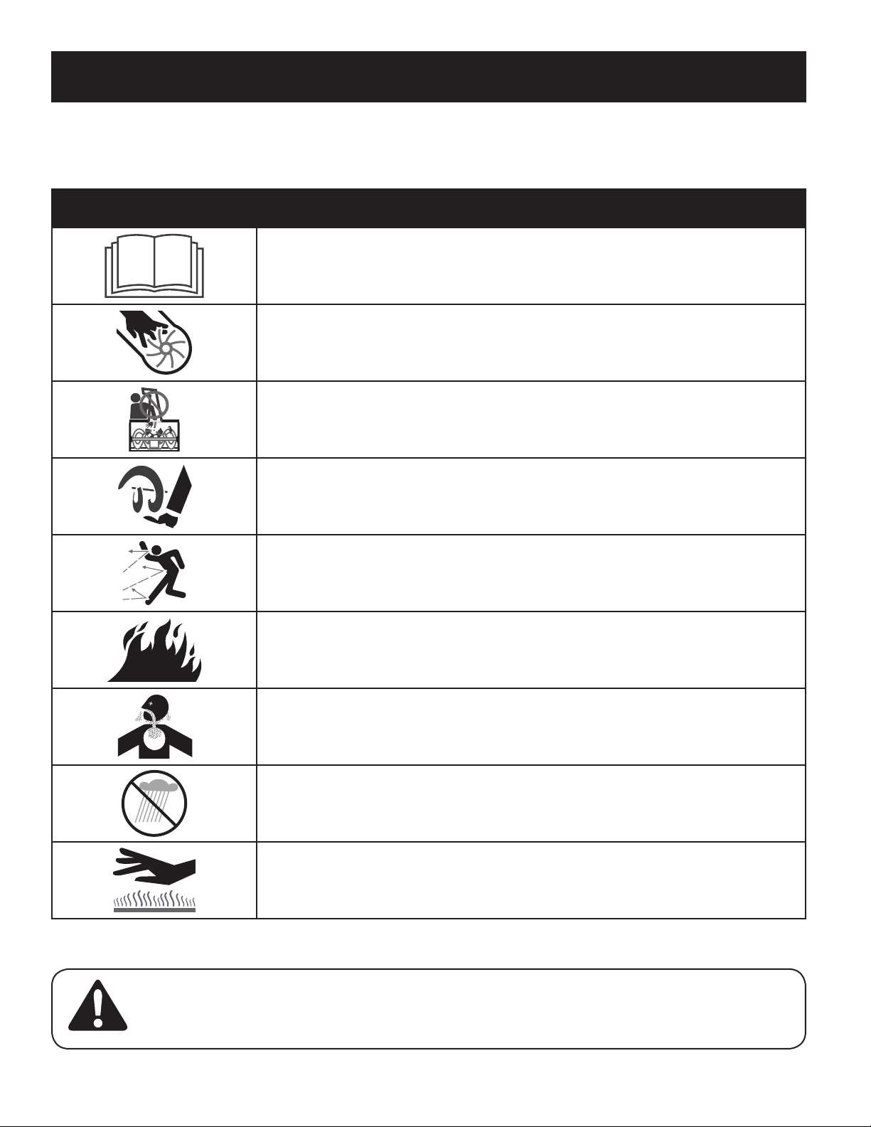
SAFETY SYMBOLS
This page depic ts and describes safety symbols that may appear on this product. Read, understand, and follow all instructions on the machine before
attempting to assemble and operate.
Symbol Description
READ THE OPERATOR’S MANUAL(S)
Read, understand, and follow all instructions in the manual(s) before attempting to assemble and
operate
WARNING— ROTATING BLADES
Keep hands out of inlet and discharge openings while machine is running. There are rotating blades
inside
WARNING— ROTATING BLADES
Keep hands out of inlet and discharge openings while machine is running. There are rotating blades
inside
WARNING— ROTATING AUGER
Do not put hands or feet near rotating parts, in the auger/impeller housing or chute assembly.
Contact with the rotating parts can amputate hands and feet.
WARNING—THROWN OBJECTS
This machine may pick up and throw and objects which can cause serious personal injury.
WARNING—GASOLINE IS FLAMMABLE
Allow the engine to cool at least two minutes before refueling.
WARNING— CARBON MONOXIDE
Never run an engine indoors or in a poorly ventilated area. Engine exhaust contains carbon
monoxide, an odorless and deadly gas.
WARNING— ELECTRICAL SHOCK
Do not use the engine’s electric starter in the rain
WARNING— HOT SURFACE
Engine parts, especially the muffler, become extremely hot during operation. Allow engine and
muffler to cool before touching.
WARNING: Your Responsibility—Restrict the use of this power machine to persons who read, understand and follow
the warnings and instructions in this manual and on the machine.
SAVE THESE INSTRUCTIONS!
6
ASSEMBLY
Wing
Knob
Carriage Bolts
Wing
Knob
Carriage Bolt
Wing
Knob
NOTE: All references to the left or right side of the snow thrower are from the
Wing Knob
Wing Knob
Carriage Bolts
operator’s position. Any exceptions will be noted.
Unpacking the Snow Thrower
1. Open the top of the carton.
2. Cut down the corners on the front of the carton and fold down the front side.
3. Pull the snow thrower out of the carton. Be sure not to damage the chute,
chute rotation control assembly or any cables attached to the chute. Some
of these parts are shipped under the shroud on the backside of the carton.
Check for any cable ties securing the chute and remove if necessary.
Assembly
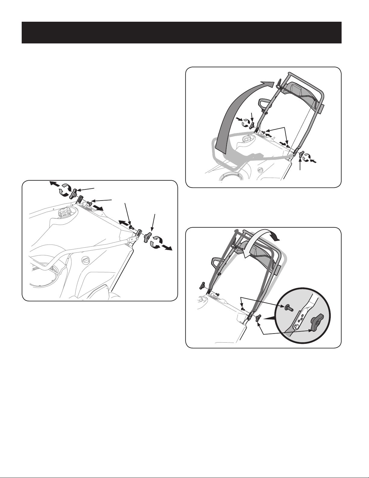
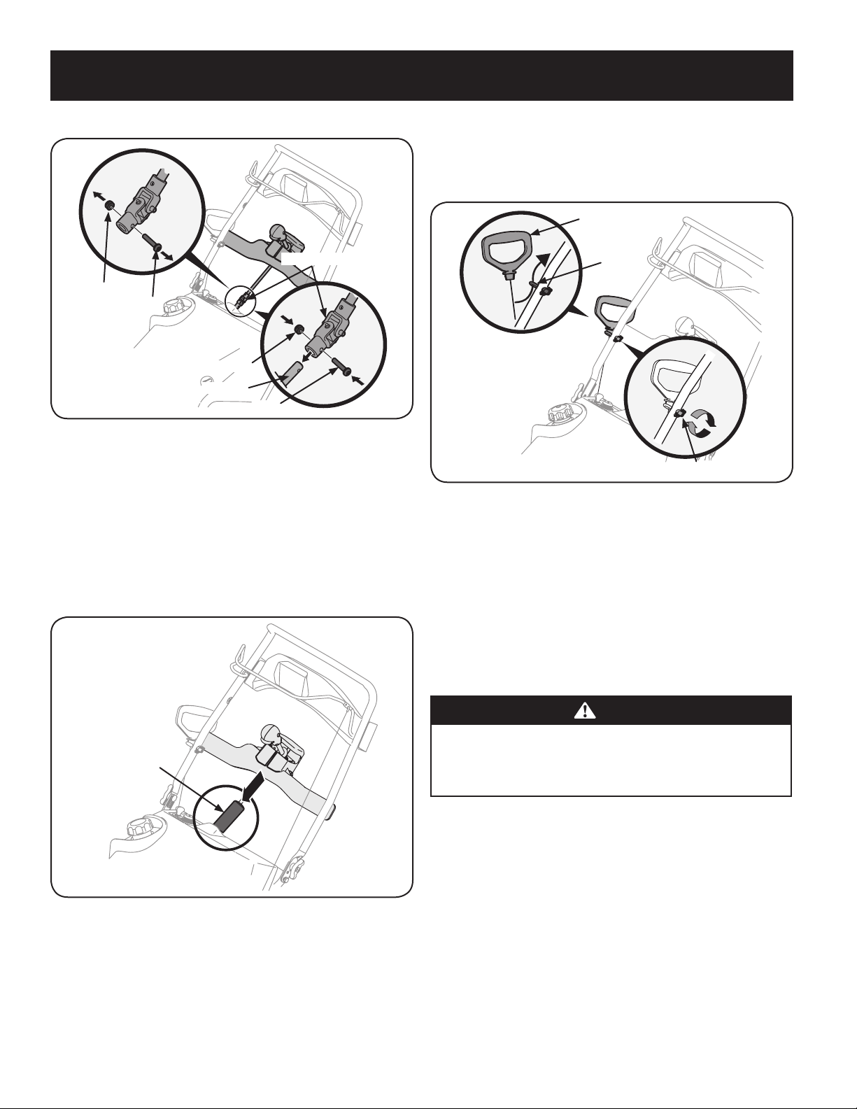
Positioning the Upper Handle
1. Remove the wing knob and carriage bolt from the top of the lower handle.
See Figure 1. It is not necessary to remove the shoulder screw and flange lock
nut below the wing knob and carriage bolt.
2. Pivot the upper handle into the operating position. Be sure not to pinch any
of the cables in the process. See Figure 2.
Figure 2
3. The handle can be set in three different positions. Place the handle in the
desired position and then install wing knobs and carriage bolts in the
appropriate hole and secure the handle. See Figure 3.
Figure 1
Figure 3
7
ASSEMBLY
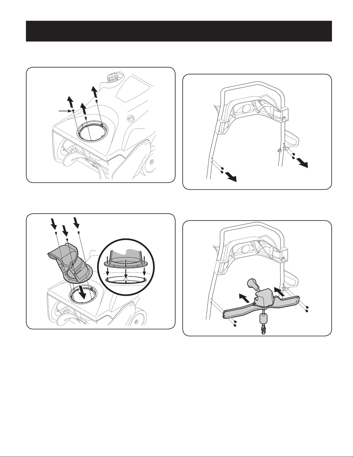
Installing the Chute
Hex
Washer
Screw
1. Remove the hex washer screws in the chute base. See Figure 4.
Figure 4
2. Align the holes in the chute base with the holes in the lower chute and
secure with the previously removed hex washer screws. See Figure 5.
Installing the Chute Rotation Control Assembly
1. Remove the four hex washer screws from the back of the handle (two on
each side). See Figure 6.
Figure 6
2. Using the four hex washer screws, install the chute rotation control
assembly. See Figure 7.
Figure 5
Figure 7
8
ASSEMBLY
3. Remove the screw and hex lock nut from the universal joint. See Figure 8.
Hex Lock Nut
Screw
Universal Joint
Hex Lock Nut
Chute Rod
Screw
Protective Sleeve
Recoil Starter Handle
Eye Bolt
Handle Knob
Figure 8
NOTE: Make sure the chute is facing f orward when installing the univers al joint.
4. Install the universal joint on the end of the chute rod as shown in Figure 8.
NOTE: Be sure the holes in the universal joint line up with the holes in the
chute rod. You may have to activate the chute rotation control trigger to
allow you to line up the holes.
5. Secure the universal joint with the hex nut and screw previously removed.
See Figure 8.
6. Slide the protective sleeve over the universal joint. See Figure 9.
Installing the Recoil Starter Handle
1. Remove the eye bolt and handle knob from the manual bag.
2. Place the eye bolt and handle knob on the upper handle as shown in Figure
10. Do not fully tighten the hardware until instructed to do so.
Figure 10
NOTE: The opening of the eye bolt should face toward the back of the snow
thrower.
3. Slowly pull the recoil starter handle up towards the eye bolt.
4. Slip the recoil starter rope into the eye bolt from the back of the snow thrower.
See Figure 10.
5. Securely tighten the eye bolt and handle knob.
Figure 9
Set-Up
Fuel Recommendations
CAUTION
Operating the engine with E15 or E85 fuel, an oil/gasoline mixture, dirty
gasoline, or gasoline over 30 days old without fuel stabilizing additive
may result in damage to your engine’s carburetor. Subsequent damage
would not be covered under the manufacturer’s warranty.
Use automotive gasoline (unleaded or low leaded to minimize combustion chamber
deposits) with a minimum of 87 octane. Gasoline with up to 10% ethanol (E10)
or 15% MTBE (Methyl Tertiary Butyl Ether) can be used. Never use an oil/gasoline
mixture or dir ty gasoline. Avoid getting dirt, dust, or water in the fuel tank. DO
NOT use E15 or E85 gasoline.
• Refuel in a well-ventilated area with the engine stopped. Do not smoke or
allow flames or sparks in the area where the engine is refueled or where
gasoline is stored.
• Do not overfill the fuel tank. After refueling, make sure the tank cap is closed
properly and securely.
• Be careful not to spill fuel when refueling. Spilled fuel or fuel vapor may
ignite. If any fuel is spilled, make sure the area is dr y before starting the
engine.
• Avoid repeated or prolonged contact with skin or breathing of vapor.
9
ASSEMBLY
Adding Fuel
WARNING
Use extreme care when handling gasoline. Gasoline is extremely
flammable and the vapors are explosive. Never fuel the machine indoors or
while the engine is hot or running. Extinguish cigarettes, cigars, pipes and
other sources of ignition.
WARNING
Always keep hands and feet clear of equipment moving parts. Do not use a
pressurized starting fluid. Vapors are flammable.
1. Remove the gas cap, check the fuel level and add fuel if necessary. Fill the
tank until the fuel reaches 1/2” below the bottom of the filler neck to allow
for fuel expansion. Be careful not to overfill.
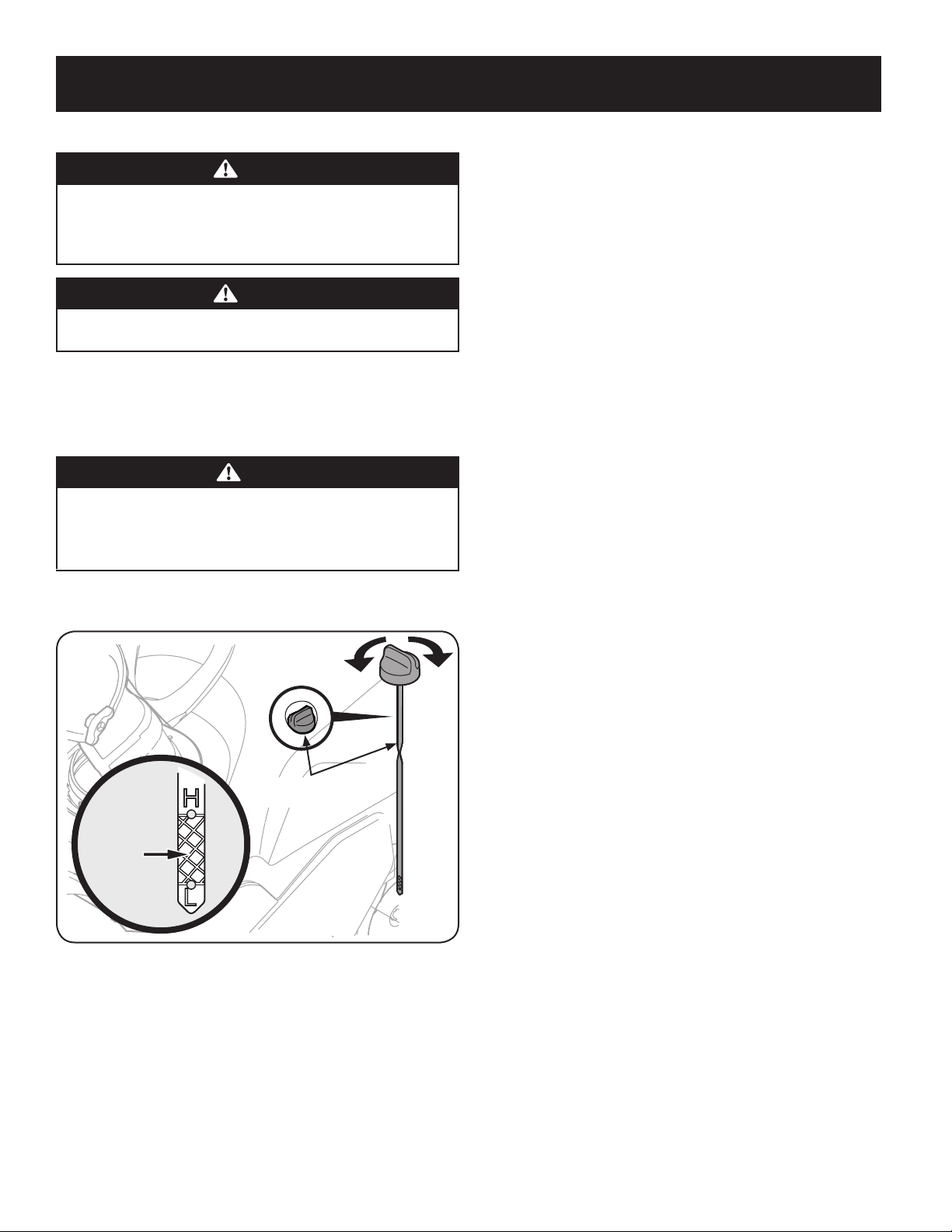
Checking & Adding Oil
CAUTION
The engine is shipped without oil in the engine. You must fill the engine
with SAE 5W-30 oil, shipped with your unit, before operating. Running
the engine with insufficient oil can cause serious engine damage and void
the product warranty.
5. Replace and tighten oil filler cap/dipstick firmly before starting engine.
NOTE: DO NOT allow oil level to fall below the "L" mark on the dipstick.
Doing so may result in equipment malfunctions or damage.
NOTE:
To change the oil on your engine, see the Service and Maintenance
section of this manual.
1. Place the snow thrower on a flat, level surface.
2. Remove the oil filler cap/dipstick and wipe the dipstick clean. See Figure 11.
Oil Filler Cap/
Dipstick
Fill
between
the high
and low
marks
Figure 11
3. Insert the oil filler cap/dipstick into the oil filler neck, but do not screw it in.
4. Remove the oil filler cap/dipstick. Slowly add oil into the reservoir until oil
level registers between high (H) and low (L), Figure 11.
NOTE: Do not overfill. Overfilling with oil may cause smoking, hard starting,
or spark plug fouling.
10
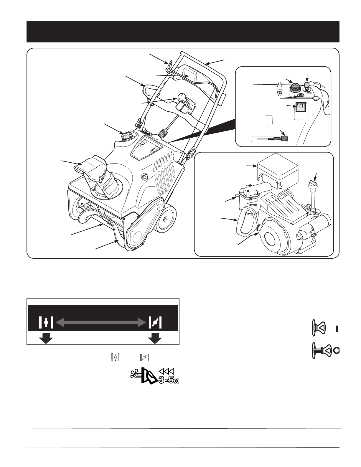
OPERATION
Chute Assembly
Shave Plate
Auger
Recoil Starter Handle
Gas Cap
Auger Control
Choke Lever
Primer
Key
Electric Starter Outlet
Electric Starter Button
Oil Fill/Dipstick
Muffler
Recoil Starter
Handle
Choke Lever
Oil Drain
Headlight
Chute Rotation Control
Upper Handle
Now that you have set up your snow thrower, it’s important to become acquainted
with its controls and features. Refer to Figure 1.
Choke Control
Figure 1
Recoil Starter Handle
The recoil starter handle is used to start the engine.
Gas Cap
RUN
RUN
Activating the choke control closes the choke plate on carburetor and aids in star ting
engine. The choke lever slides bet ween the RUN
Primer
Pressing the primer, making sure to cover the vent hole
when pushing, forces fuel directly into the engine’s
carburetor to aid in cold-weather starting.
CHOKE BELOW
Craftsman Snow Throwers conform to the safety standard of the American National Standards Institute (ANSI).
CHOKE
CHOKE
and CHOKE positions.
Meets ANSI Safety Standards
Remove the gas cap to add fuel.
Key
The key is a safety device. It must be fully inserted in order for the
engine to start. Remove the key when the snow thrower is not in use.
NOTE: Do not turn the key in an attempt to start the engine.
Doing so may cause it to break.
Auger
When engaged, the auger rotation draws snow into the auger housing and throws
it out the discharge chute. Rubber paddles on the auger also aid in propelling the
snow thrower as they come in contact with the pavement.
11
OPERATION
Auger Control
Located on the upper handle, the auger control handle is used to engage and disengage
drive to the auger. Squeeze the control handle against the upper handle to engage the
auger; release it to disengag e.
Muffler
Engine exhaust exits the engine via the muf fler.
Chute Rotation Control
The chute rotate control is located in the center of the control panel and controls the
direction snow is thrown. Depress the but ton and rotate the chute rotation control to the
right to turn the chute to the right and rotate to the lef t to turn the chute to the left.
Chute Assembly
The pitch of the discharge chute controls the angle at which the snow is thrown. Loosen
the wing knob on the side of t he discharge chute before pivoting the discharge chute
upward or downward. Retighten the knob once the desired position has been achieved.
Shave Plate
The shave plate maintains contact with the pavement as the snow thrower is
propelled, allowing snow close to the pavement’s surface to be discharged.
Oil Fill/Dipstick
Engine oil level can be checked and oil added through the oil fill.
Oil Drain
Engine oil can be drained through the oil drain.
Headlight
The headlight is located on the upper center of the control panel and is on when the
snow thrower is running.
Electric Starter Outlet
Requires the use of a three-prong outdoor extension cord and a 120V power source/
wall outlet.
Electric Starter Button
Pressing the electric starter button engages the engine’s electric starter when plugged
into a 120V power source.
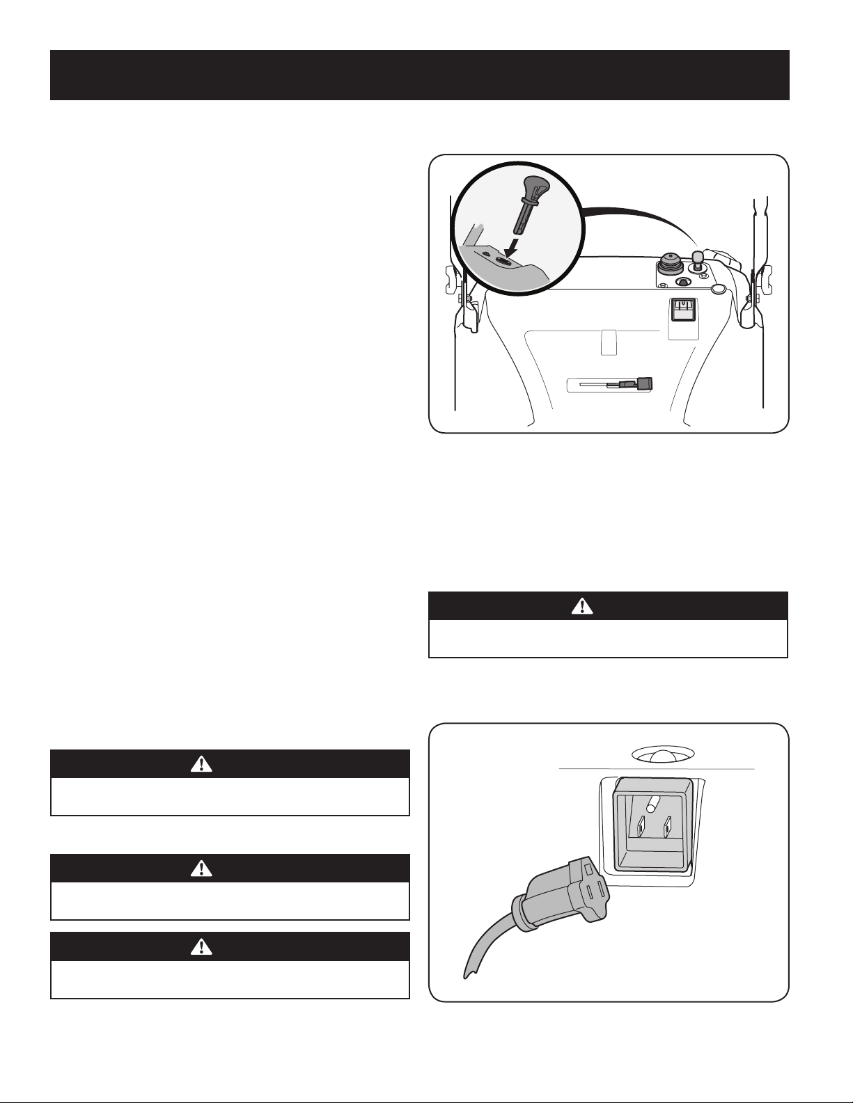
2. Insert ignition key into slot. Make sure it snaps into place. Do not attempt to
turn the key. See Figure 2.
Figure 2
NOTE: The engine cannot start unless the key is fully inserted into the
ignition switch.
Electric Starter
Determine that your home’s wiring is a three-wire grounded system. Ask a licensed
electrician if you are not certain.
If you have a grounded three-prong receptacle, proceed as follows:
CAUTION
The extension cord can be any length, but must be rated for 15 amps at
125 volts, grounded and rated for outdoor use.
1. Plug the ex tension cord into the outlet located on the engine’s surface. Plug the
other end of extension cord into a three-prong 120-volt, grounded, AC outlet in a
w
ell-ventilated area See Figure 3.
Before Starting the Engine
WARNING
Read, understand and follow all the instructions and warnings on the
machine and in this manual before operating.
Starting The Engine
WARNING
Always keep hands and feet clear of moving parts. Do not use a pressurized
starting fluid. Vapors are flammable.
WARNING
To avoid carbon monoxide poisoning, make sure the engine is outdoors in a
well-ventilated area.
1. Make certain the auger control is in the disengaged (released) position.
Figure 3
12

OPERATION
2. Push the choke lever to the CHOKE position.
3. If the engine is warm, place the choke in the RUN position instead of
CHOKE .
4. Push the primer three (3) to five (5) times, making sure to cover the vent hole
when pushing.
5. If the engine is warm, push the primer button only once.
6. Push starter button to start engine.
7. Once the engine starts, release starter button.
8. Allow the engine to warm up several minutes, adjusting choke toward RUN
position. Wait until engine runs smoothly before each choke adjustment.
9. When disconnecting the extension cord, always unplug the end
at the three-prong wall outlet before unplugging the opposite end
from the snow thrower.
Recoil Starter
1. Push the choke lever to the CHOKE position.
2. If the engine is warm, place the choke in the RUN position instead of
CHOKE .
3. Push the primer three (3) to five (5) times, making sure to cover the vent
hole when pushing.
4. If the engine is warm, push the primer button only once.
Stopping the Engine
1. Run the engine for a few minutes without load before stopping to help dry
off any moisture on the engine.
. To stop the engine remove the key and store it in a safe place.
2
NOTE: Remove the key to quickly stop the engine in the event of an
emergency.
. Wipe all the snow and moisture away from the engine controls area.
3
WARNING
Muffler, engine and surrounding areas become hot and can cause a burn.
Be careful and do not touch when they are hot.
Engaging the Auger
Engage the auger by squeezing the auger control against the upper handle. Release
the control to stop the auger.
Engaging the Drive
Lift up slightly on the upper handle to allow the rubber paddles on the auger to
contact the pavement and propel the snow thrower forward. Pushing downward on
the handle will raise the auger of f the ground and stop the forward motion.
NOTE: Excessive upward pressure on the handle will result in premature
wear to the rubber auger paddles, which will not be covered by the warrant y.
WARNING
When pulling the starter rope, the rope can unexpectedly jerk back toward
the engine causing serious injury. To avoid this risk, carefully follow the
instructions below.
5
. Grasp the recoil starter handle and slowly pull the rope out. At the point
where it becomes slightly harder to pull the rope, slowly allow the rope to
recoil.
6. Pull the starter handle with a firm, rapid stroke. Do not release the handle
and allow it to snap back. Keep a firm hold on the starter handle and allow
it to slowly recoil.
7. Allow the engine to warm up several minutes, adjusting choke toward
RUN position. Wait until engine runs smoothly before each choke
adjustment.
Clearing a Clogged Discharge Chute
Hand contact with the rotating impeller inside the discharge chute is the most common
cause of injury associated with snow throwers. Never use your hand to clean out the
discharge chute.
To clear the chute:
1. Stop the engine. See instructions above for how to stop the engine.
2. Wait 10 seconds to be sure the impeller blades have stopped rotating.
3. Always use a clean-out tool or stick, not your hands.
Operating the Snow Thrower
• Once the auger drive is engaged, roll the snow thrower into the layer of snow
to be removed.
• Adjust the chute so that the snow is not thrown over other snow that is to be
removed.
• Prevent possible property d
planning your snow throwing pattern to avoid discharge towards windows,
walls, cars, etc.
• Do not overload machine capacity by attempting to clear snow at too fast of a
rate.
• Never operate this machine without good visibility or light.
• Always be sure of your footing and keep a firm hold on the handles.
• Walk, never run when operating snow thrower.
• Look down and behind and use care when backing up.
amage or personal injury from object ricochet by
13
SERVICE AND MAINTENANCE
MAINTENANCE SCHEDULE
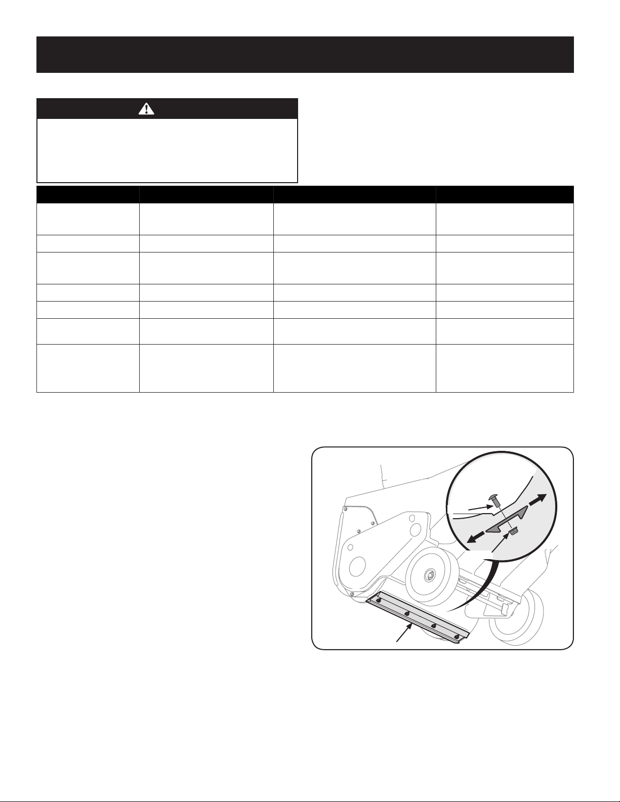
Side View
Lock Nut
Screw
Reversible Shave Plate
WARNING
Before performing any type of maintenance/service, disengage all controls
and stop the engine. Wait until all moving parts have come to a complete
stop. Disconnec t spark plug wire and ground it against the engine to
prevent unintended starting. Always wear safety glasses during operation
or while performing any adjustments or repairs.
Interval Item Service Service Log
Each use 1. Engine oil level.
2. Snow thrower and exhaust area.
1st 5 hours 1. Engine oil. 1. Change.
Every 5 hours 1. Engine oil.
2. Exhaust area.
25 hours 1. Spark plug. 1. Check. (See engine manual)
Every season/50 hours 1. Engine oil. 1. Change.
Every season/100 hours 1. Spark plug. 1. Clean, replace, re-gap. (See engine
Every season/Before storage 1. Pivot points.
2. Control handle.
3. Extension spring.
1. Check.
2. Clean.
1. Check.
2. Clean.
1. Lubricate.
2. Lubricate.
3. Lubricate.
Follow the maintenance schedule given below. This chart describes service guidelines
only. Use the Service Log column to keep track of completed maintenance tasks. To
schedule service from Sear s Parts & Repair, call 1-888-331-4569.
manual)
Maintenance
Engine
Refer to the Engine Operator’s Manual for all engine maintenance procedures.
Checking, adding and changing oil are also found in this manual.
Lubrication
Lubricate the pivot points on the control handle and the extension spring at the end
of the control cable with a light oil once every season and before the snow thrower
is put into storage at the end of the season.
Adjustments
Shave Plate
To check the adjustment of the shave plate, place the machine on a level surface.
The wheels, shave plate and auger paddles should all contact the level surface.
Note that if the shave plate is adjusted too high, snow may blow under the auger
housing. If the shave plate wears out excessively, or the snow thrower does not
self-propel, the shave plate may be too low to the ground and needs to be adjusted.
NOTE: On new snow throwers or machines with a new shave plate installed, the
auger paddles may be slightly of f the ground.
To adjust the shave plate proceed as follows:
1. Run the snow thrower until the fuel tank is empty.
2. Pull the starter cord until resistance is felt. Then tip the snow thrower back
until it rests on the handles. To ensure that the snow thrower does not tip
forward, it may be necessary to secure the handle to the ground with a block
or other object.
3. Loosen the four flange lock nuts and carriage screws which secure the shave
plate to the housing. See Figure 1. Move the shave plate to the appropriate
position and retighten the nuts and screws securely.
Figure 1
4. Tip the snow thrower back to the operating position and pull the recoil
starter handle a few times to see if it is dif ficult to pull.
14
SERVICE AND MAINTENANCE
5. If the starter is diff icult to pull, remove the spark plug and pull the handle
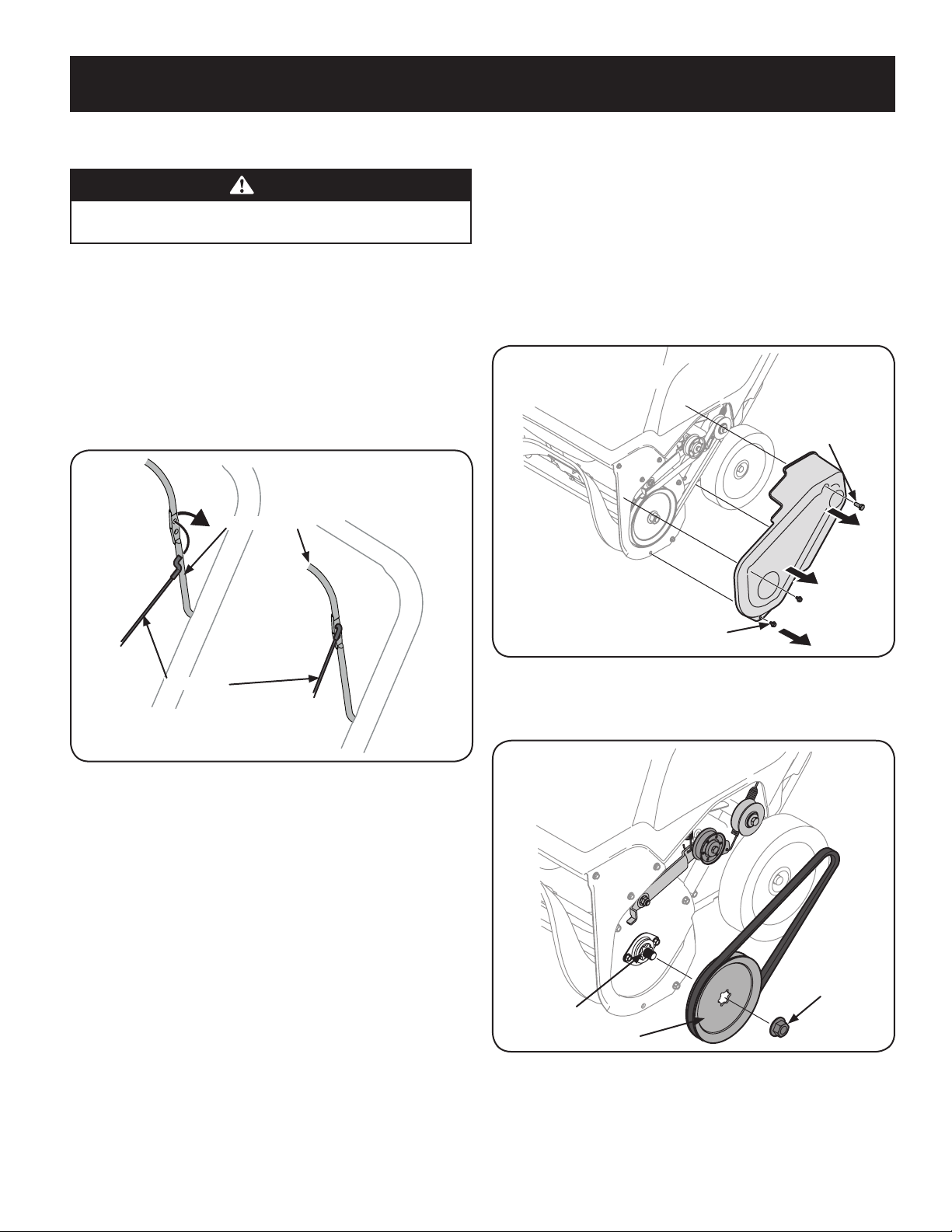
Control Cable
Control Handle
Hex Washer Screw
Hex Lock Scr ew
Flange Nut
Auger Pulley
Auger Shaft
several times to ensure that any oil trapped in the engine head is removed.
CAUTION
Oil may come out of the spark plug hole when it is removed and the starter
handle is pulled.
6. Inspect the spark plug. If it is wet, clean off any oil before re-installing.
Control Cable
As a result of both the control cable and the auger drive belt stretching due to
wear, periodic adjustments may be necessary. If the auger seems to hesitate when
rotating, proceed as follows:
1. The upper hole in the control handle provides for an adjustment in cable
tension. To adjust, disconnect the end of control cable from the bottom hole
in the control handle and reinsert it in the upper hole. Inser t the cable from
the outside as shown in Figure 2.
Service
Auger Drive Belt Replacement
1. Run the snow thrower until the fuel tank is empty.
2. Pull the recoil starter handle until resistance is felt. Then tip the snow
thrower back until it rests on the handles.
3. Slide a board up through the auger and through the chute to secure the
auger in place.
4. Remove the belt cover by removing the two hex washer screws and one hex
lock screw that secure it to the frame. See Figure 3.
Figure 2
2. Test the snow thrower to see if there is a noticeable difference. If after the
adjustment to the control cable the auger still hesitates when rotating, see
Auger Drive Belt Replacement for instructions on replacing the belt.
Chute Assembly
Refer to the Assembly section for instructions on adjusting the chute assembly.
Figure 3
5. Remove the flange nut that secures the auger pulley to the auger shaft. See
Figure 4.
Figure 4
6. Remove the auger pulley and the belt.
5
1