

Craftsman 247887001 Owner’s Manual
Owner's Manual
5 Horse Power
22" Two-Stage
Snow Thrower
Model No.
247.887001
CAUTION: Before
using this product,
read this manual and
follow all safety rules
and operating
instructions.
Sears, Roebuck And Co., Hoffman Estates, IL 60179, U.S.A.
Visit our website: www.sears.com/craftsman FORM NO. 769-00750C
Printed in U.S.A. (7/30/2004)
Safety
Assembly
Operation
Service
Maintenance
Espa5ol, p.29
Content Page
Warranty Information .................................... 2
Safe Operation Practices .............................. 3
Assembly ...................................................... 5
Operation ...................................................... 7
Maintenance ................................................. 11
Content Page
Service & Adjustment ....................................... 13
Off-Season Storage ......................................... 15
Trouble-Shooting ............................................. 16
Parts List ......................................................... 18
Espan51 ......................................................... 29
Two -Year Warranty on Craftsman Snow Thrower
For two years from the date of purchase, when this Craftsman Snow Thrower is maintained, lubricated and tuned up according to the instruc-
tions in the owner's manual, Sears will repair, free of charge, any defect in material and workmanship.
If this Craftsman snow thrower is used for commercial or rental purposes, this warranty applies for only 30 days from the date of purchase.
This warranty does not cover:
Expendable items which become worn during normal use, such as skid shoes, shave plate and spark plugs.
Repairs necessary because of operator abuse or negligence, including bent crankshafts and the failure to maintain the equipment
according to the instructions contained in the owner's manual.
WARRANTY SERVICE IS AVAILABLE BY RETURNING THE CRAFTSMAN SNOW THROWER TO THE NEAREST SEARS PARTS & REPAIR
CENTER IN THE UNITED STATES.
This warranty applies only while this product is in use in the United States.
This warranty gives you specific legal rights and you may also have other rights which may vary from state to state.
SEARS, ROEBUCK AND CO., D/817WA, HOFFMAN ESTATES, IL 60179
Repair Protection Agreements
Congratulations on making a smart purchase.Your new Craftsman®
product is designed and manufactured for years of dependable
operation. But like all products, it may require repair from time to
time. That's when having a Repair Protection Agreement can save
you money and aggravation.
Here's what's included in the Agreement:
Expert service by our 12,000 professional repair
_t specialists
Unlimited service and no charge for parts and labor on
all covered repairs
Product replacement ifyour covered product can't be
@P fixed
Discount of 10% from regular price of service and service-
related parts not covered by the agreement; also, 10% off
regular price of preventive maintenance check
Fast help by phone - phone support from a Sears
technician on products requiring in-home repair, plus
convenient repair scheduling
Purchase a Repair Protection Agreement now and protect yourself
from unexpected hassle and expense.
Once you purchase the Agreement, a simple phone call is all that it
takes for you to schedule service. You can call anytime day or night,
or schedule a service appointment online. Sears has over 12,000
professional repair specialists, who have access to over 4.5 million
quality parts and accessories. That's the kind of professionalism you
can count on to help prolong the life of your new purchase for years
to come. Purchase your Repair Protection Agreement today!
Some limitations and exclusions apply. For prices and additional
information call 1-800-827-6655.
Sears Installation Service
For Sears professional installation of home appliances, garage door
openers, water heaters, and other major home items, inthe U.S.A.
call 1-800-4-MY-HOME®.
Horsepower: 5
Engine Oil: SAE 5W30 Capacity: 21 oz.
Fuel: Unleaded Regular Capacity:
Spark Plug: RJ19LM
Eng ne: Craftsman Eng ne Mode 143.045003
Model Number ...........................................................
Serial Number ...........................................................
Date of Purchase ......................................................
Record both serial number and date of purchase and keep in a
safe place for future reference.
_, ARNING: This symbol points out important safety instructions which, if not followed, could endangerthe personal safety and/or property of yourself and others. Read and follow all instructions in this manual
before attempting to operate this machine. Failure to comply with these instructions may result in personal
injury. When you see this symbol--heed its warning.
_L ARNING: Engine Exhaust, some of its constituents, and certain vehicle components contain or emitchemicals known to State of California to cause cancer and birth defects or other reproductive harm.
DANGER: This machine was built to be operated according to the rules for safe operation in this manual. As with
any type of power equipment, carelessness or error on the part of the operator can result in serious injury. This
machine is capable of amputating hands and feet and throwing objects. Failure to observe the following safety
instructions could result in serious injury or death.
Training
1. Read, understand, and follow ail instructions on the
machine and in the manual(s) before attempting to
assemble and operate. Keep this manual in a safe place
for future and regular reference and for ordering
replacement parts.
2. Be familiar with all controls and their proper operation.
Know how to stop the machine and disengage these
controls quickly.
3. Never allow children under 14 years old to operate this
machine. Those 14 years old and over should read and
understand the operation instructions and safety rules in
this manual and be trained and supervised by a parent in
order to operate this equipment.
4. Never allow adults to operate this machine without proper
instruction.
5. Thrown objects can cause serious personal injury. Plan
your snow throwing pattern to avoid discharge of material
toward roads, bystanders and the like.
6. Keep bystanders, helpers, pets and children at least 75
feet from the machine while it is in operation. Stop
machine if anyone enters the area.
7. Exercise caution to avoid slipping or falling, especially
when backing up.
Preparation
1. Thoroughly inspect the area where the equipment is to be
used. Remove all door mats, newspapers, sleds, boards,
wires and other foreign objects which could be tripped
over or thrown by the auger/impeller.
2. Always wear safety glasses or eye shields during
operation and while performing an adjustment or repair to
protect your eyes. Thrown objects which ricochet can
cause serious injury to the eyes.
3. Do not operate without wearing adequate winter outer
garments. Do not wear jewelry, long scarves or other
loose clothing which could become entangled in moving
parts. Wear footwear which will improve footing on
slippery surfaces.
4. Use a grounded three wire extension cord and receptacle
for all units with electric start engines.
5. Adjust collector housing height to clear gravel or crushed
rock surfaces.
6. Disengage all control levers before starting the engine.
Never attempt to make any adjustments while engine is
running, except where specifically recommended in the
operator's manual.
8.
Let engine and machine adjust to outdoor temperature
before starting to clear snow.
9.
To avoid personal injury or property damage use extreme
care in handling gasoline. Gasoline is extremely
flammable and the vapors are explosive. Serious
personal injury can occur when gasoline is spilled on
yourself or your clothes which can ignite. Wash your skin
and change clothes immediately.
a. Use only an approved gasoline container.
b. Extinguish all cigarettes, cigars, pipes and other
sources of ignition.
c. Never fuel machine indoors.
d. Never remove gas cap or add fuel while the
engine is hot or running.
e. Allow engine to cool at least two minutes before
refueling.
f. Never over-fill fuel tank. Fill tank to no more than
1/zinch below bottom of filler neck to provide space
for fuel expansion.
g. Replace gasoline cap and tighten securely.
h. If gasoline is spilled, wipe it off the engine and
equipment. Move machine to another area. Wait 5
minutes before starting the engine.
i. Never store the machine or fuel container inside
where there is an open flame, spark or pilot light
(e.g. furnace, water heater, space heater, clothes
dryer etc.).
j. Allow machine to cool at least 5 minutes before
storing.
Operation
1. Do not put hands or feet near rotating parts, in the auger/
impeller housing or chute assembly. Contact with the
rotating parts can amputate hands and feet.
2. The auger/impeller control lever is a safety device. Never
bypass its operation. Doing so makes the machine
unsafe and may cause personal injury.
3. The control levers must operate easily in both directions
and automatically return to the disengaged position when
released.
4. Never operate with a missing or damaged chute
assembly. Keep all safety devices in place and working.

5. Neverrunanengineindoorsorinapoorlyventilated
area.Engineexhaustcontainscarbonmonoxide,an
odorlessanddeadlygas.
6. Donotoperatemachinewhileundertheinfluenceof
alcoholordrugs.
7. Mufflerandenginebecomehotandcancauseaburn.Do
nottouch.
8. Exerciseextremecautionwhenoperatingonorcrossing
gravelsurfaces.Stayalertforhiddenhazardsortraffic.
9. Exercisecautionwhenchangingdirectionandwhile
operatingonslopes.
10.Planyoursnowthrowingpatterntoavoiddischarge
towardswindows,walls,carsetc.Toavoidproperty
damageorpersonalinjurycausedbyaricochet.
11.Neverdirectdischargeatchildren,bystandersandpets
orallowanyoneinfrontofthemachine.
12.Donotoverloadmachinecapacitybyattemptingtoclear
snowattoofastofarate.
13.Neveroperatethismachinewithoutgoodvisibilityor
light.Alwaysbesureofyourfootingandkeepafirmhold
onthehandles.Walk,neverrun.
14.Disengagepowertotheauger/impellerwhen
transportingornetinuse.
15.Neveroperatemachineathightransportspeedson
slipperysurfaces.Lookdownandbehindandusecareif
youarebackingup.
16.Ifthemachineshouldstarttovibrateabnormally,stopthe
engine,disconnectthesparkplugandgrounditagainst
theengine.Inspectthoroughlyfordamage.Repairany
damagebeforestartingandoperating.
17.Disengageallcontrolleversandstopenginebeforeyou
leavetheoperatingposition(behindthehandles).Wait
untiltheauger/impellercomestoacompletestopbefore
uncloggingthechuteassembly,makinganyadjustments,
orinspections.
18.Neverputyourhandinthedischargeorcollector
openings.Alwaysusetheclean-outtoolprovidedto
unclogthedischargeopening.Donotunclogchute
assemblywhiletheengineisrunning.
19.Useonlyattachmentsandaccessoriesapprovedbythe
manufacturer(e.g.wheelweights,tirechains,cabsetc.).
20.Ifsituationsoccurwhicharenotcoveredinthismanual,
usecareandgoodjudgment.ContactyournearestSears
storeforassistanceorcallCustomerService.
Maintenance & Storage
1. Never tamper with safety devices. Check their proper
operation regularly.
2. Disengage all bails and stop engine. Wait until the auger/
impeller come to a complete stop. Disconnect the spark
plug wire and ground against the engine to prevent
unintended starting before cleaning, repairing, or
inspecting.
3. Check bolts, and screws for proper tightness at frequent
intervals to keep the machine in safe working condition.
Also, visually inspect machine for any damage.
4. Do not change the engine governor setting or over-speed
the engine. The governor controls the maximum safe
operating speed of the engine.
5. Snow thrower shave plates and skid shoes are subject to
wear and damage. For your safety protection, frequently
check all components and replace with original
equipment manufacturer's (O.E.M.) parts only. "Use of
parts which do not meet the original equipment
specifications may lead to improper performance and
compromise safety!"
6. Check all controls periodically to verify they engage and
disengage properly and adjust, if necessary. Refer to the
adjustment section in this operator's manual for
instructions.
7. Maintain or replace safety and instruction labels, as
necessary.
8. Observe proper disposal laws and regulations for gas,
oil, etc. to protect the environment.
9. Prior to storing, run machine a few minutes to clear snow
from machine and prevent freeze up of auger/impeller.
10. Never store the machine or fuel container inside where
there isan open flame, spark or pilot light such as a water
heater, furnace, clothes dryer etc.
11. Always refer to the operator's manual for proper
instructions on off-season storage.
Your Responsibility
Restrict the use of this power equipment to persons who read,
understand and follow warnings and instructions in this
manual and on the machine.
Do not modify engine
To avoid serious injury or death, do not modify engine in any
way. Tampering with the governor setting can lead to a
runaway engine and cause it to operate at unsafe speeds.
Never tamper with factory setting of engine governor.
Notice regarding Emissions
Engines which are certified to comply with California and
federal EPA emission regulations for SORE (Small Off Road
Equipment) are certified to operate on regular unleaded
gasoline, and may include the following emission control
systems: Engine Modification (EM) and Three Way Catalyst
(TWC) if so equipped.
IMPORTANT: This unit is shipped with the engine full
of oil. After assembly, see page 8for fuel and oil fill-up
details.
Removing From Carton
1. Cut the corners of the carton and lay the sides flat
on the ground. Remove all packing inserts.
2. Move the snow thrower out of the carton.
3. Make certain the carton has been completely
emptied before discarding it.
Knob
Handle Tab
%_o- Hex Bolt
Before Assembly
NOTE: Reference to right, left, front or rear of the unit is
from the operating position unless otherwise stated.
• Cut and remove cable ties holding upper handle to
chute assembly.
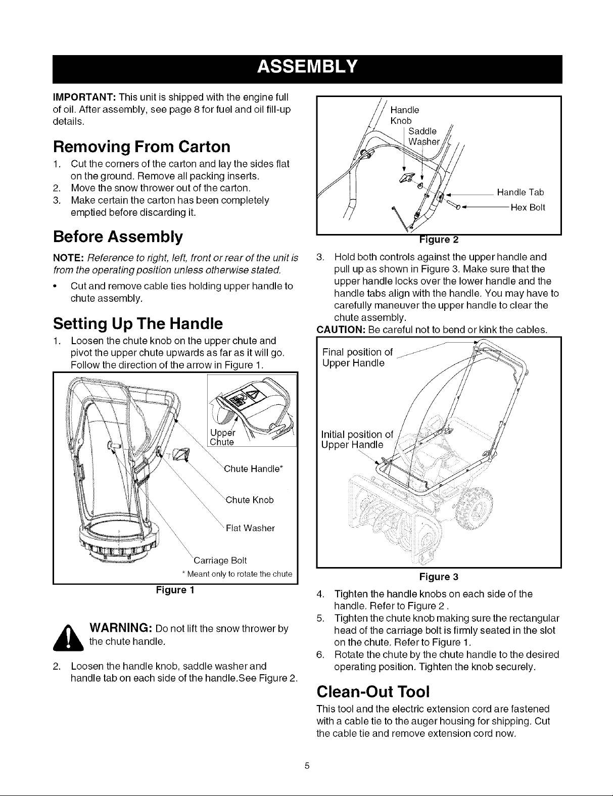
Setting Up The Handle
1. Loosen the chute knob on the upper chute and
pivot the upper chute upwards as far as it will go.
Follow the direction of the arrow in Figure 1.
Flat Washer
Figure 2
3. Hold both controls against the upper handle and
pull up as shown in Figure 3. Make sure that the
upper handle locks over the lower handle and the
handle tabs align with the handle. You may have to
carefully maneuver the upper handle to clear the
chute assembly.
CAUTION: Be careful not to bend or kink the cables.
J
Final position of/_
Upper Handle
Initial position of
Upper Handle
J
'Carriage Bolt
* Meant only to rotate the chute
Figure 1
_ ARNING: Do not lift the snow thrower by
2. Loosen the handle knob, saddle washer and
the chute handle.
handle tab on each side of the handle.See Figure 2.
Figure 3
4. Tighten the handle knobs on each side of the
handle. Refer to Figure 2.
5. Tighten the chute knob making sure the rectangular
head of the carriage bolt is firmly seated in the slot
on the chute. Refer to Figure 1.
6. Rotate the chute by the chute handle to the desired
operating position. Tighten the knob securely.
Clean-Out Tool
This tool and the electric extension cord are fastened
with a cable tie to the auger housing for shipping. Cut
the cable tie and remove extension cord now.
Final Adjustments
IMPORTANT:Check the adjustments as instructed and
make any final adjustments necessary before operating
the unit. Check all nuts and bolts for tightness.Failure to
follow these instructions may cause damage to unit.
Tire Pressure (Pneumatic Tires)
The tires are over-inflated for shipping purposes. Check
tire pressure and reduce pressure, if needed, to 10-15
psi. Maintain equal pressure on both wheels of the
snow throwe r.
_ WARNING: Maximum tire pressure underany circumstance is 15 psi. Equal tire pressure
should be maintained at all times. Excessive
pressure (over 15 psi) when seating beads
may cause tire/rim assembly to burst with force
sufficient to cause serious injury
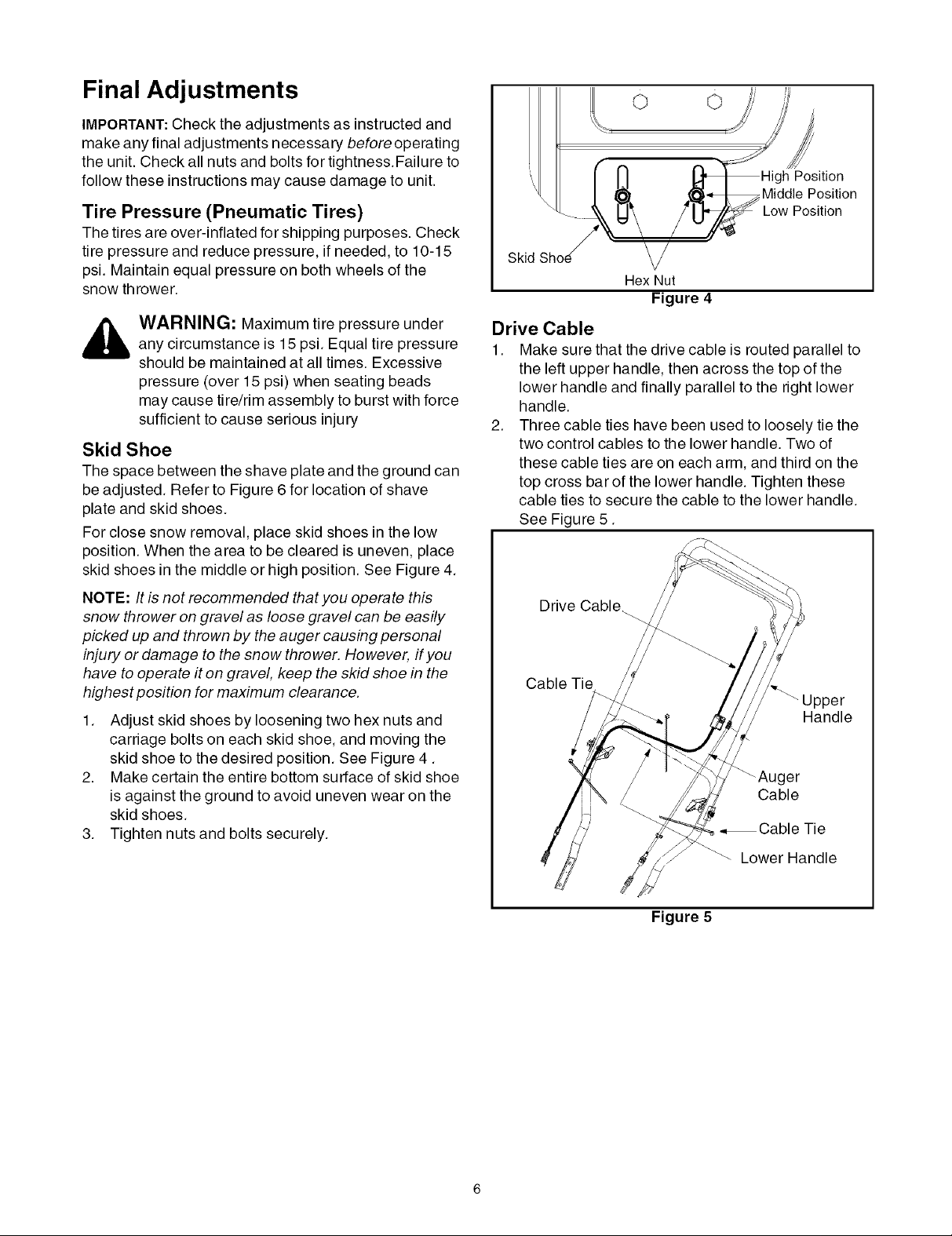
Skid Shoe
The space between the shave plate and the ground can
be adjusted. Refer to Figure 6 for location of shave
plate and skid shoes.
For close snow removal, place skid shoes in the low
position. When the area to be cleared is uneven, place
skid shoes in the middle or high position. See Figure 4.
o o
Position
Middle Position
Low Position
Skid
Hex Nut
Figure 4
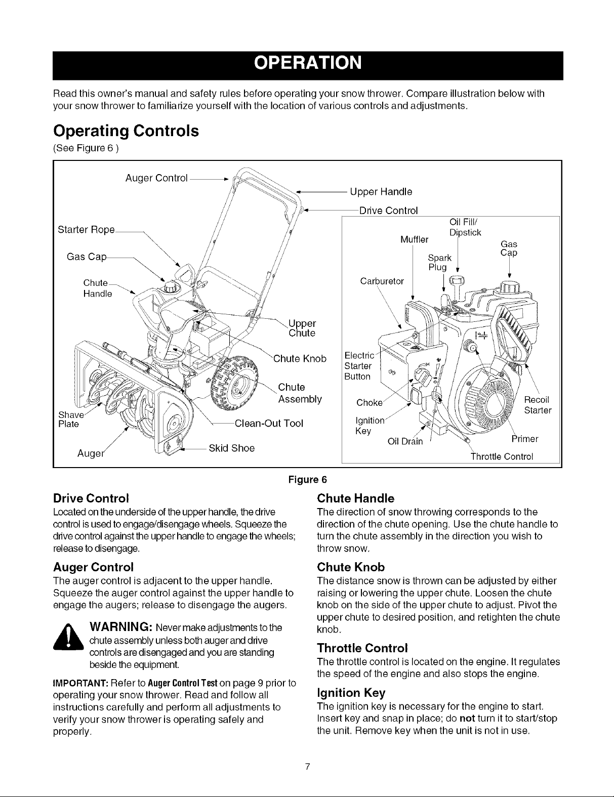
Drive Cable
1. Make sure that the drive cable is routed parallel to
the left upper handle, then across the top of the
lower handle and finally parallel to the right lower
handle.
2. Three cable ties have been used to loosely tie the
two control cables to the lower handle. Two of
these cable ties are on each arm, and third on the
top cross bar of the lower handle. Tighten these
cable ties to secure the cable to the lower handle.
See Figure 5.
NOTE: It is not recommended that you operate this
snow thrower on gravel as loose gravel can be easily
picked up and thrown by the auger causing personal
injury or damage to the snow thrower. However, if you
have to operate it on gravel, keep the skid shoe in the
highest position for maximum clearance.
1. Adjust skid shoes by loosening two hex nuts and
carriage bolts on each skid shoe, and moving the
skid shoe to the desired position. See Figure 4.
2. Make certain the entire bottom surface of skid shoe
is against the ground to avoid uneven wear on the
skid shoes.
3. Tighten nuts and bolts securely.
Drive Cable_
Cable Tie
Handle
_Auger
Cable
•,Cable Tie
Lower Handle
Figure 5
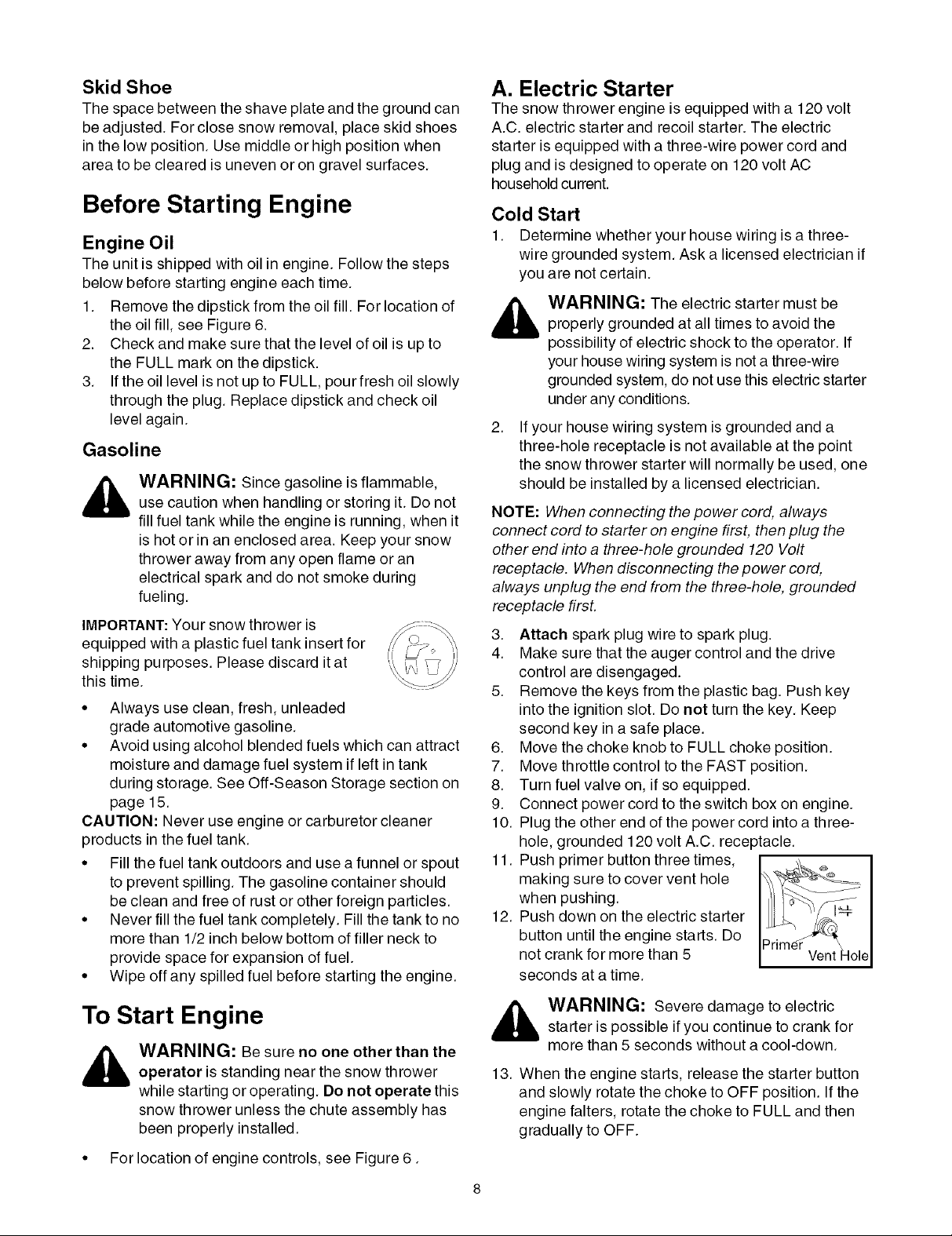
Read this owner's manual and safety rules before operating your snow thrower. Compare illustration below with
your snow thrower to familiarize yourself with the location of various controls and adjustments.
Operating Controls
(See Figure 6 )
Auger Control
Upper Handle
Drive Control
Oil Fill/
Starter Rope_
ShE
Plate
Auger _
\
Carburetor
Chute
Knob
Chute
Assembly
Clean-Out Tool
Choke /
Ignition _
Keg
Shoe
M" Dipstick
UTHer I
Spark |
Plug _.
\.
\\
\
\
\
Oil Drain
Gas
°ip
\
\
Primer
Throttle Control
Recoil
Starter
Drive Control
Located on the underside ofthe upper handle, thedrive
control is used to engage/disengage wheels. Squeeze the
drivecontrol against the upper handle to engage thewheels;
releaseto disengage.
Auger Control
The auger control is adjacent to the upper handle.
Squeeze the auger control against the upper handle to
engage the augers; release to disengage the augers.
WAR N ING: Never make adjustments tothe
chute assembly unless bothauger and drive
controls are disengaged and you are standing
beside the equipment.
IMPORTANT:Refer to AugerControlTeston page 9 prior to
operating your snow thrower. Read and follow all
instructions carefully and perform all adjustments to
verify your snow thrower is operating safely and
properly.
Figure 6
Chute Handle
The direction of snow throwing corresponds to the
direction of the chute opening. Use the chute handle to
turn the chute assembly in the direction you wish to
throw snow.
Chute Knob
The distance snow is thrown can be adjusted by either
raising or lowering the upper chute. Loosen the chute
knob on the side of the upper chute to adjust. Pivot the
upper chute to desired position, and retighten the chute
knob.
Throttle Control
The throttle control is located on the engine. Itregulates
the speed of the engine and also stops the engine.
Ignition Key
The ignition key is necessary for the engine to start.
Insert key and snap in place; do not turn it to start/stop
the unit. Remove key when the unit is not in use.
Skid Shoe
The space between the shave plate and the ground can
be adjusted. For close snow removal, place skid shoes
in the low position. Use middle or high position when
area to be cleared is uneven or on gravel surfaces.
Before Starting Engine
Engine Oil
The unit is shipped with oil in engine. Follow the steps
below before starting engine each time.
1. Remove the dipstick from the oil fill. For location of
the oil fill, see Figure 6.
2. Check and make sure that the level of oil is up to
the FULL mark on the dipstick.
3. If the oil level is not up to FULL, pour fresh oil slowly
through the plug. Replace dipstick and check oil
level again.
A. Electric Starter
The snow thrower engine is equipped with a 120 volt
A.C. electric starter and recoil starter. The electric
starter is equipped with a three-wire power cord and
plug and is designed to operate on 120 volt AC
household current.
Cold Start
1. Determine whether your house wiring is a three-
_ ARNING: The electric starter must beproperly grounded at all times to avoid the
2. If your house wiring system is grounded and a
Gasoline
_ ARNING: Since gasoline is flammable,use caution when handling or storing it. Do not
fill fuel tank while the engine is running, when it
is hot or in an enclosed area. Keep your snow
thrower away from any open flame or an
electrical spark and do not smoke during
fueling.
IMPORTANT:Your snow thrower is
equipped with a plastic fuel tank insert for
shipping purposes. Please discard it at
this time.
• Always use clean, fresh, unleaded
grade automotive gasoline.
• Avoid using alcohol blended fuels which can attract 6.
moisture and damage fuel system if left in tank 7.
during storage. See Off-Season Storage section on 8.
page 15. 9.
CAUTION: Never use engine or carburetor cleaner 10.
products in the fuel tank.
• Fill the fuel tank outdoors and use a funnel or spout 11.
to prevent spilling. The gasoline container should
be clean and free of rust or other foreign particles.
• Never fill the fuel tank completely. Fill the tank to no 12.
more than 1/2 inch below bottom of filler neck to
provide space for expansion of fuel.
• Wipe off any spilled fuel before starting the engine.
NOTE: When connecting the power cord, always
connect cord to starter on engine first, then plug the
other end into a three-hole grounded 120 Volt
receptacle. When disconnecting the power cord,
always unplug the end from the three-hole, grounded
receptacle first.
3.
4.
wire grounded system. Ask a licensed electrician if
you are not certain.
possibility of electric shock to the operator. If
your house wiring system is not a three-wire
grounded system, do not use this electric starter
under any conditions.
three-hole receptacle is not available at the point
the snow thrower starter will normally be used, one
should be installed by a licensed electrician.
Attach spark plug wire to spark plug.
Make sure that the auger control and the drive
control are disengaged.
Remove the keys from the plastic bag. Push key
into the ignition slot. Do not turn the key. Keep
second key in a safe place.
Move the choke knob to FULL choke position.
Move throttle control to the FAST position.
Turn fuel valve on, if so equipped.
Connect power cord to the switch box on engine.
Plug the other end of the power cord into a three-
hole, grounded 120 volt A.C. receptacle.
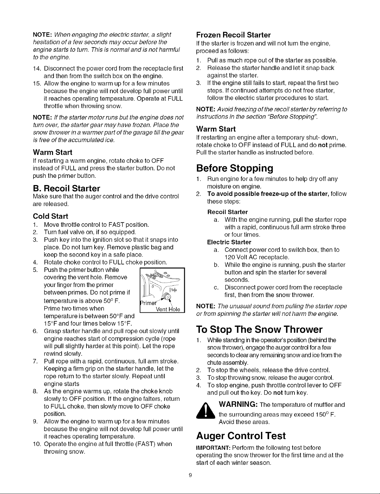
Push primer button three times,
making sure to cover vent hole
when pushing.
Push down on the electric starter
button until the engine starts. Do
not crank for more than 5
seconds at a time.
To Start Engine
_ ARNING: Be sure no one other than theoperator is standing near the snow thrower
while starting or operating. Do not operate this
snow thrower unless the chute assembly has
been properly installed.
• For location of engine controls, see Figure 6.
_ ARNING: Severe damage to electric
13. When the engine starts, release the starter button
starter is possible if you continue to crank for
more than 5 seconds without a cool-down.
and slowly rotate the choke to OFF position. If the
engine falters, rotate the choke to FULL and then
gradually to OFF.
NOTE:When engaging the electric starter, a slight
hesitation of a few seconds may occur before the
engine starts to turn. This is normal and is not harmful
to the engine.
14. Disconnect the power cord from the receptacle first
and then from the switch box on the engine.
15. Allow the engine to warm up for a few minutes
because the engine will not develop full power until
it reaches operating temperature. Operate at FULL
throttle when throwing snow.
NOTE: If the starter motor runs but the engine does not
turn over, the starter gear may have frozen. Place the
snow thrower in a warmer part of the garage till the gear
is free of the accumulated ice.
Warm Start
If restarting a warm engine, rotate choke to OFF
instead of FULL and press the starter button. Do not
push the primer button.
B. Recoil Starter
Make sure that the auger control and the drive control
are released.
Cold Start
1. Move throttle control to FAST position.
2. Turn fuel valve on, if so equipped.
3. Push key into the ignition slot so that it snaps into
place. Do not turn key. Remove plastic bag and
keep the second key in a safe place.
4. Rotate choke control to FULL choke position.
5. Push the primer button while
covering the vent hole. Remove
your finger from the primer
between primes. Do not prime if
temperature is above 50° F.
Prime two times when
temperature is between 50°F and
15°F and four times below 15°F.
6. Grasp starter handle and pull rope out slowly until
engine reaches start of compression cycle (rope
will pull slightly harder at this point). Let the rope
rewind slowly.
7. Pull rope with a rapid, continuous, full arm stroke.
Keeping a firm grip on the starter handle, let the
rope return to the starter slowly. Repeat until
engine starts
8. As the engine warms up, rotate the choke knob
slowly to OFF position. If the engine falters, return
to FULL choke, then slowly move to OFF choke
position.
9. Allow the engine to warm up for a few minutes
because the engine will not develop full power until
it reaches operating temperature.
10. Operate the engine at full throttle (FAST) when
throwing snow.
Frozen Recoil Starter
If the starter is frozen and will not turn the engine,
proceed as follows:
1. Pull as much rope out of the starter as possible.
2. Release the starter handle and let it snap back
against the starter.
3. If the engine still fails to start, repeat the first two
steps. If continued attempts do not free starter,
follow the electric starter procedures to start.
NOTE: Avoid freezing of the recoil starter by referring to
instructions in the section "Before Stopping".
Warm Start
If restarting an engine after atemporary shut- down,
rotate choke to OFF instead of FULL and do not prime.
Pull the starter handle as instructed before.
Before Stopping
1. Run engine for a few minutes to help dry off any
moisture on engine.
2. To avoid possible freeze-up of the starter, follow
these steps:
Recoil Starter
a. With the engine running, pull the starter rope
with a rapid, continuous full arm stroke three
or four times.
Electric Starter
a. Connect power cord to switch box, then to
120 Volt AC receptacle.
b. While the engine is running, push the starter
button and spin the starter for several
seconds.
c. Disconnect power cord from the receptacle
first, then from the snow thrower.
NOTE: The unusual sound from pulling the starter rope
or from spinning the starter will not harm the engine.
To Stop The Snow Thrower
1. While standing inthe operator's position (behind the
snow thrower), engage the auger control fora few
seconds to clear any remaining snow and icefrom the
chute assembly.
2. To stop the wheels, release the drive control.
3. To stop throwing snow, release the auger control.
4. To stop engine, push throttle control lever to OFF
and pull out the key. Do not turn key.
_lb ARNING: The temperature of muffler and
the surrounding areas may exceed 150 ° F.
Avoid these areas.
Auger Control Test
IMPORTANT:Perform the following test before
operating the snow thrower for the first time and at the
start of each winter season.
Checktheadjustmentoftheaugercontrolasfollows:
• Whentheaugercontrolisreleasedandinthe
disengaged"up"position,thecableshouldhave
verylittleslack,butshouldNOTbetight.
Operating Tips
NOTE: Allow the engine to warm up for a few minutes
as the engine will not develop full power until it reaches
operating temperature.
,_ WARNING: Do not over-tighten the cable.
• In a well-ventilated area, start the snow thrower
• While standing in the operator's position (behind
• Allow the auger to remain engaged for
• With the engine running inthe FAST position and
• Confirm that the auger has completely stopped
IMPORTANT: If the auger shows ANY signs of rotating,
immediately return to the operator's position and shut
off the engine. Wait for all moving parts to stop before
readjusting the auger control cable as shown in the
"Adjustments" on page 14.
Over-tightening may prevent the auger from
disengaging and compromise the safety of the
snow thrower.
engine as instructed earlier inthis section under the
heading StartingEngine.Make sure the throttle is set
in the FAST position.
the snow thrower) engage the auger.
approximately ten (10) seconds before releasing
the auger control. Repeat this several times.
the auger control in the disengaged "up" position,
walk to the front of the machine.
rotating and shows NO signs of motion.
Clearing the Snow
_ ARNING: The temperature of muffler and
• For most efficient snow removal, remove snow
• Discharge snow downwind whenever possible.
• Set the skid shoes 1/4" below the shave plate for
NOTE: It is not recommended that you operate this
snow thrower on gravel as loose gravel can be easily
picked up and thrown by the auger causing personal
injury and/or damage to the snow thrower.
• If for some reason, you have to operate the snow
• Clean the snow thrower thoroughly after each use.
surrounding areas may exceed 150° F. Avoid
these areas.
immediately after it falls.
Slightly overlap each previous swath.
normal usage. The skid shoes may be adjusted
upward for hard-packed snow.
thrower on gravel, keep the skid shoe in the highest
position for maximum clearance between the
ground and the shave plate.
Clean-Out Tool
CAUTION: Check the area to be cleared for foreign
objects. Remove, if any.
1. Start the engine following Starting instructions.
2. Rotate the chute assembly to the desired direction,
away from bystanders and/or buildings.
3. Making certain no bystanders or obstacles are in
front of the unit, squeeze the auger control
completely against the upper handle to fully engage
the augers.
4. While the auger control is engaged, squeeze the
drive control completely against the upper handle
to engage the wheels.
5. As the snow thrower starts to move, maintain a firm
hold on the handle, and guide the snow thrower
along the path to becleared.
6. Release the auger and drive controls to stop the
snow throwing action and forward motion.
NOTE: Yourunit is equipped with a clutch in the
transmission. If the wheels stop turning while trying to
discharge large volumes of snow, immediately
disengage drive control and allow rotating augers to
discharge snow from the housing. Continue operation
on a narrower stretch with less volume of snow.
_ WARNING: Stop engine by moving throttlelever to stop position and wait for ALL moving
parts to stop, before using the clean-out tool.
Theclean-out tool isconveniently fastened to the rear ofthe
auger housing with a mounting clip.
When snow and ice collect in thechute assembly during
operation, use this tool to safely clean the chute and chute
opening. Follow the steps below to operate it:
1. Release both auger and drive control.
2. Stop the engine by moving throttle lever to stop
position.
3. Remove the clean-out tool from the clip which secures
itto the rear of the auger housing.
4. Use the shovel-shaped end of the clean-out tool to
dislodge and scoop any snow and ice which has
formed in and near the chute assembly.
_ WARNING: Never use your hands to cleansnow and ice from the chute assembly or auger
housing.
5. Re-fasten the clean-out toolto the mounting clip on the
rearof theauger housing.You can now re-start the snow
thrower's engine for more snow cleaning.
7. On each succeeding pass, readjust the chute
assembly to the desired position and slightly
overlap the previously cleared path.
10
General Recommendations
• Always observe safety rules when performing any
maintenance.
• The warranty on this snow thrower does not cover
items that have been subjected to operator abuse
or negligence. To receive full value from the
warranty, operator must maintain the snow
thrower as instructed in this manual.
• Some adjustments will have to be made
periodically to maintain your unit properly.
Maintenance Schedule
Maint. Tasks
Product:
Lubricate pivot points
Check V belts
Engine:
Check engine oil
Change engine oil
Check spark plug
4
4
Every 25
hours
operation
• All adjustments in the Service and Adjustments
section of this manual should be checked at least
once each season.
• Follow maintenance schedule on this page.
• Periodically check all fasteners and make sure
these are tight.
_ ARNING: Always stop the engine anddisconnect the spark plug wire before
performing any maintenance or adjustments.
Every
100 hrs.
operation
Service Dates
4
4
4
Replace spark plug
Empty fuel system
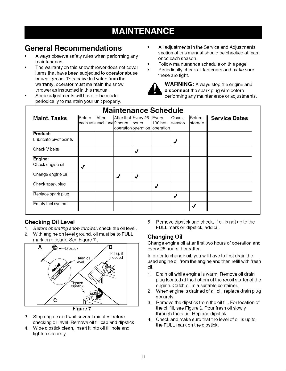
Checking Oil Level
1. Before operating snow thrower, check the oil level.
2. With engine on level ground, oil must be to FULL
mark on dipstick. See Figure 7.
A_"_ Dipstick
3. Stop engine and wait several minutes before
checking oil level. Remove oil fill cap and dipstick.
4. Wipe dipstick clean, insert itinto oil fill hole and
tighten securely.
Read oil
Figure 7
5. Remove dipstick and check. Ifoil is not up to the
FULL mark on dipstick, add oil.
Changing Oil
Change engine oil after first two hours of operation and
every 25 hours thereafter.
In order to change oil, you will have to first drain the
used engine oil from the engine and then refill with fresh
oil.
1. Drain oil while engine is warm. Remove oil drain
plug located at the bottom of the recoil starter of the
engine. Catch oil in a suitable container.
2. When engine is drained of all oil, replace drain plug
securely.
3. Remove the dipstick from the oil fill. For location of
the oil fill, see Figure 6. Pour fresh oil slowly
through the plug. Replace dipstick.
4. Check and make sure that the level of oil is up to
the FULL mark on the dipstick.
11
Spark Plug
Clean spark plug and reset the electrode gap to 0.030"
at least once a season or every 100 hours of operation;
replace every 200 hours of operation.
• Clean area around the spark plug base.
• Remove and inspect the spark plug.
• Replace the spark plug if electrodes are pitted,
burned, orthe porcelain is cracked. See Figure 8.
NOTE: Do not sandblast spark plug. Spark plug should
be cleaned by scraping or wire brushing and washing
with a commercial solvent.
Electrodes
.030" Porcelain
Gap
Figure 8
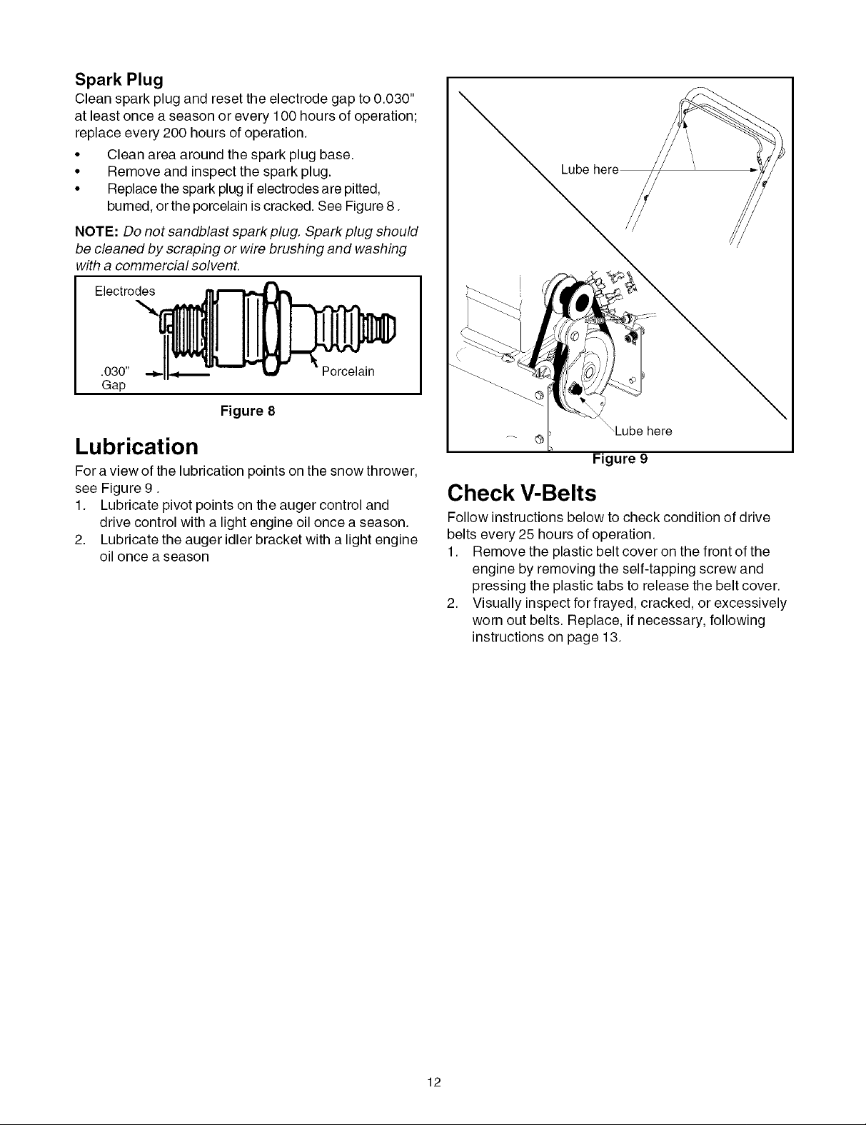
Lubrication
For a view of the lubrication points on the snow thrower,
see Figure 9.
1. Lubricate pivot points on the auger control and
drive control with a light engine oil once a season.
2. Lubricate the auger idler bracket with a light engine
oil once a season
Lube
,Lube here
Figure 9
Check V-Belts
Follow instructions below to check condition of drive
belts every 25 hours of operation.
1. Remove the plastic belt cover on the front of the
engine by removing the self-tapping screw and
pressing the plastic tabs to release the belt cover.
2. Visually inspect for frayed, cracked, or excessively
worn out belts. Replace, if necessary, following
instructions on page 13.
12
WARNING: Always stop the engine of the
snow thrower, disconnect spark plug wire and
move it away from the spark plug before
performing any adjustments or repairs.
WARNING: Never attempt to clean the
chute assembly or make any adjustments while
the engine is running. Always wear safety
glasses during operation or while performing
any adjustments or repairs.
Shave Plate & Skid Shoes
The shave plate and skid shoes on the bottom of the
snow thrower are subject to wear. They should be
checked periodically and replaced when necessary.
1. Remove the four carriage bolts, and hex nuts which
attach skid shoes to the snow thrower on two sides.
See Figure 10.
2. Reassemble new skid shoes with the four carriage
bolts, and hex nuts. Make certain the skid shoes
are adjusted to be level.
3. To remove shave plate, remove skid shoe and rest
of the hardware including carriage bolts, and hex
nuts which attach shave plate to the snow thrower
housing. For location of shave plate, see Figure 10.
4. Reassemble new shave plate, making sure heads
of the carriage bolts are to the inside of the housing.
Reinstall skid shoe. Tighten securely.
Shear Pin
Cotter Pin
If the augers do not turn, check to see if the pins have
sheared. Replace, if needed, with proper shear pins.
refer to item 22 on page 22 for part number.
IMPORTANT:NEVER replace the auger shear pins with
standard pins or fasteners. Any damage to the auger
gearbox or other components, as a result of doing so,
will NOT be covered by your snow thrower's warranty.
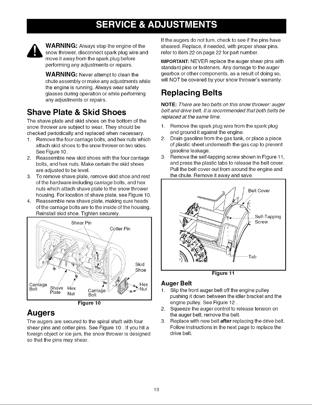
Replacing Belts
NOTE: There are two belts on this snow thrower: auger
belt and drive bell It is recommended that both belts be
replaced at the same time.
1. Remove the spark plug wire from the spark plug
and ground it against the engine.
2. Drain gasoline from the gas tank, or place a piece
of plastic sheet underneath the gas cap to prevent
gasoline leakage.
3. Remove the self-tapping screw shown in Figure 11,
and press the plastic tabs to release the belt cover.
Pull the belt cover out from around the engine and
the chute. Remove it away and save.
Belt Cover
/
Lpping
Screw
Skid
/Shoe
Carriage
Bolt
Sha/ve Hex Carria _Age
Plate Nut Bolt
Figure 10
Augers
The augers are secured to the spiral shaft with four
shear pins and cotter pins. See Figure 10. Ifyou hit a
foreign object or ice jam, the snow thrower is designed
so that the pins may shear.
Figure 11
Auger Belt
1. Slip the front auger belt off the engine pulley
pushing it down between the idler bracket and the
engine pulley. See Figure 12.
2. Squeeze the auger control to release tension on
the auger belt; remove the belt.
3. Replace with new belt after replacing the drive belt.
Follow instructions in the next page to replace the
drive belt.
13
Engine Pulley
Drive Belt
\
\
\
Auger Belt
)___Auger Pulley
_ Idler Bracket
Figure 12
Drive Belt
NOTE: Replace the drive belt before reassembling the
new auger belt.
1. Tip the snow thrower up and forward so that it rests
on the auger housing.
2. Remove the spring that connects the transmission
to a bolt on the engine frame. See Figure 13.
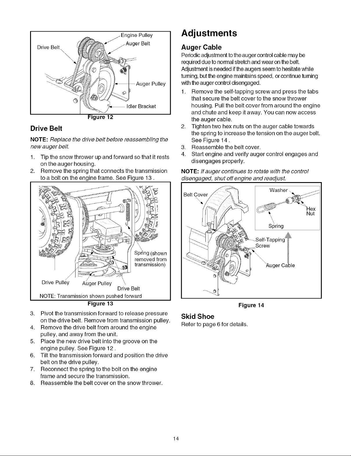
Adjustments
Auger Cable
Periodicadjustment to the auger control cable may be
required due to normal stretch and wear on thebelt.
Adjustment isneeded ifthe augers seem to hesitatewhile
turning, butthe engine maintains speed, orcontinue turning
with theauger control disengaged.
1. Remove the self-tapping screw and press the tabs
that secure the belt cover to the snow thrower
housing. Pull the belt cover from around the engine
and chute and keep it away. You can now access
the auger cable.
2. Tighten two hex nuts on the auger cable towards
the spring to increase the tension on the auger belt.
See Figure 14.
3. Reassemble the belt cover.
4. Start engine and verify auger control engages and
disengages properly.
NOTE: If auger continues to rotate with the control
disengaged, shut off engine and readjust.
\\
\
Spring (shown
removed from
transmission)
iger Pulley
Drive Belt
NOTE:Transmission shown pushed forward
Figure 13
3. Pivot the transmission forward to release pressure
on the drive belt. Remove from transmission pulley.
4. Remove the drive belt from around the engine
pulley, and away from the unit.
5. Place the new drive belt into the groove on the
engine pulley. See Figure 12.
6. Tilt the transmission forward and position the drive
belt on the drive pulley.
7. Reconnect the spring to the bolt on the engine
frame and secure the transmission.
8. Reassemble the belt cover on the snow thrower.
BeltCover _-
Washer ..
Figure 14
Skid Shoe
Refer to page 6 for details.
Nut
14
 Loading...