

Craftsman 247886510 Owner’s Manual
owner's
manual
MODEL NO.
247.886510
CAUTION:
Read
INSTRUCTIONS
carefully
Sold by Sears, Roebuck and Co., Chicago, IL 60684
Part No. 770-6870D
_/-___/_R,_/ CRRFT$MRN®
23" - 5 H.P. DUAL STAGE
SNOW THROWER
Optional Electric Starter Available
=Assembly
=Operation
=Maintenance
=Repair Parts
CRAFTSMAN WARRANTY'
LIMITED TWO YEAR WARRANTY ON CRAI_SMAN SNOW THROWER
For two years from the date of purchase, whet this Craftsman Snow Thrower is maintained, lubricated and tuned up
according to the instructions in the owner's manual, Sears will repair, free of charge, any defect in material and
workmanship.
If this Craftsman Snow Thrower is used for c<;mmercial or rental purposes, this warranty applies for only 90 days from
the date of purchase.
This warranty does not cover: Expendable terns which become worn during normal use, such as spark plugs, tire
chains and shear pins.
Repairs necessary because of operator aLuse or negligence, including bent cranksh_,ffs and the failure to maintain
the equipment according to the instructk ns contained in the owner's manual.
WARRANTY SERVICE IS AVAILABLE BY CO _ITACTING THE NEAREST SERVICE CENTER/DEPARTMENT IN THE
UNITED STATES. This warranty applies only while this product is in use in the United States.
This warranty gives you specific legal rights, and you may also have other rights which vary from state to state.
SEARS, ROEBUCK AND CO.
DEP' r. 698/731A SEARS TOWER
CHICAGO, IL 60684
OWNEF:'S INFORMATION
Record the following information about youl unit so that you will be able to provide it in case of loss or theft.
DATE PURCHASED:. MODEL NO./CODE: 247.886510L
STORE WHERE PURCHASED: ADDRES_
CITY: STATE: TELEPHONE:
MAINTENANCE AGREEMENT
A SEARS MAINTENANCE AGREEMENT IS AVAILABLE FOR THIS PRODUCT. CONTACT YOUR NEAREST
SEAR S STORE FOR DETAILS.
TABLF OF CONTENTS
Page
CRAFTSMAN WARRANTY ................. 2
OWNER'S INFORMATION .................. 2
MAINTENANCE AGREEMENT .............. 2
SAFE OPERATION PRACTICES ............. 3
ASSEMBLY INSTRUCTIONS .............. 4-9
OPERATING INSTRUCTIONS ........... 10-13
MAINTENANCE ..................... 13, 14
Page
STORAGE ........................... 14, 15
ADJUSTMENT/REPAIRS ............... 15-19
TROUBLE SHOOTING GUIDE ............. 20
SNOW THROWER REPAIR PARTS ...... 22-29
ENGINE REPAIR PARTS ............... 30-34
HOW TO ORDER REPAIR PARTS .. Back Cover
IMPOR ANT
SAFE OPERATION PRACTICES FOR WALK-BEHIND SNOW THROWERS
_lb THIS SYMBOL POINTS OUT IMPORTANT SAFETY INSTRUCTIONS WHICH, IF NOT FOLLOWED COULD
ENDANGER
FOLLOW ALL INSTRUCTIONS IN THIS MANUAL BEFORE ATTEMPTING TO OPERATE YOUR SNOW
THROWER.
To reduce the potential for any injury, comply with the following safety instructions. Failure to comp|y with
the instructions may result in personal injury.
TRAINING
1. Read this owner's guide carefully. Be thoroughly familiar with
the controls and proper use of the equipment. Know how to
stop the unit and disengage the controls quickly.
2. Never allow children to operate equipment. Never allow
adults to operate equipment without proper instructions.
3. No one should operate this unit while intoxicated or while
taking medication that impairs the senses or reactions.
4. Keep the area of operation clear of all persons, especialLy
small children and pets.
5. Exercise caution to avoid slipping or falling, especially when
operating in reverse.
PREPARATION
1. Thoroughly inspect the area where the equipment is to be
used and remove all door mats, sleds, boards, wires and
other foreign objects.
2. Disengage all clutches and shift into neutral before starting
engine.
3. Do not operate equipment without wearing adequate winter
outer garments. Wear footwear which will improve footing
on slippery surfaces.
4. Check the fuel before starting the engine. Gasoline is an ex-
tremely flammable fuel. Do not fill the gasoline tank indoors,
while the engine is running, or while the engine is still hot.
Replace gasoline cap securely and wipe off any spilled
gasoline before starting the engine as it may cause_a fire or
explosion.
5. Use a grounded three wire plug-in for all units with electric
drive motors or etectric starting motors.
6. Adjust auger housing height to clear gravel or crushed rock
surface.
7. Never attempt to make any adjustments while engine is run-
ning (except where specifically recommended by
manufacturer).
8. Let engine and machine adjust to outdoor temperature before
starting to clear snow.
9. Always wear safety glasses or eye shields during operation
or while performing an adjustment or repair, to protect eyes
from foreign objects that may be thrown from the machine
in any direction.
OPERATION
1, Do not put hands or feet near rotating parts. Keep clear of
discharge opening at all times.
2. Exercise extreme caution when operating on or crossing
gravel drives, walks, or roads. Stay alert for hidden hazards
or traffic. Do not carry passengers.
3. After striking a foreign object, stop the engine, remove wire
from spark plug, and thoroughly inspect the snow thrower
for any damage. Repair the damage before restarting and
operating the snow thrower.
4. If the snow thrower should start to vibrate abnormally, stop
the engine and check immediately for the cause. Vibration
is generally a warning of trouble.
THE PERSONAL SAFETY AND/OR PROPERTY OF YOURSELF AND OTHERS. READ AND
5_ Stop engine whenever you leave the operating position,
before unclogging the augerlimpel_,r housing or discharge
guide, and making any repairs, adjustments, or inspections.
6. Take all possible precautions when leaving the unit un-
attended. Disengage the auger/impeller, shift into neutral,
stop the engine, and remove the key.
7. When cleaning, repairing, or inspecting, make certain
auger/impeller and all moving parts have stopped. Discon-
nect spark plug wire and keep away from plag to prevent
accidental starting.
8. Do not run engine indoors, except when starting engine and
transporting snow thrower in or out of building. Open doors.
Exhaust fumes are dangerous.
9. Do not clear snow across the face of slopes. Exercise ex-
treme caution when changing direction on slopes. Do not at-
tempt to clear steep slopes.
10. Never operate snow thrower without guards, plates, or other
safety protection devices in place.
11. Never operate snow thrower near glass enclosures,
automobiles, windows wells, drop offs, etc., without proper
adjustment of snow thrower discharge angle. Keep children
and pets away.
12.
Do not overload machine capacity by attempting to clear
snow at too fast a rate.
13.
Never operate the machine at high transport speeds on slip-
pery surfaces. Look behind and use care when backing.
14.
Never direct discharge at bystanders or allow anyone in front
of unit.
15.
Disengage power to auger/impeller when transporting or not
in use.
16.
Use only attachments and accessories approved by the
manufacturer of snow thrower (such as wheel weights,
counterweights, cabs, etc.).
17.
Never operate the snow thrower without good visibility or light.
Always be sure of your footing and keep a firm hold on the
handles. Walk, never run.
MAINTENANCE AND STORAGE
1. Check shear bolts, engine mounting bolts, etc., at frequent
intervals for proper tightness to be sure equipment is in safe
working condition.
2. Never store the machine with fuel in the fuel tank inside a
building where ignition sources are present, such as hot water
and space heaters, clothes dryers, and the like. Allow engine
to cool before storing in any enclosure.
3. Always refer to owner's manual instructions for important
details if snow thrower is to be stored for an extended period.
4. Maintain or replace safety and instruction labels, as
necessary.
5. Run machine a few minutes after throwing snow to prevent
freeze up of auger/impeller.
ASSEMBLY INSTRUCTIONS
Handle
Right Panel , .
Hand P] Assembly _ _-====_==,_1_
Lower
Han_dleI1 [L_ I_ "_ _'HL PPd_r
\\t_s JJ e,,
"_.'_ ._',F Hand !;hift
Traction Driv__'_ _ h_nw_ /:iod
Cable Assembly__ _ L _=_
Augers,
Cable
I Chute Cra!k Assembly
FIGURE 1.
Hand Knobs
5/16" Cupped
Wa _ers
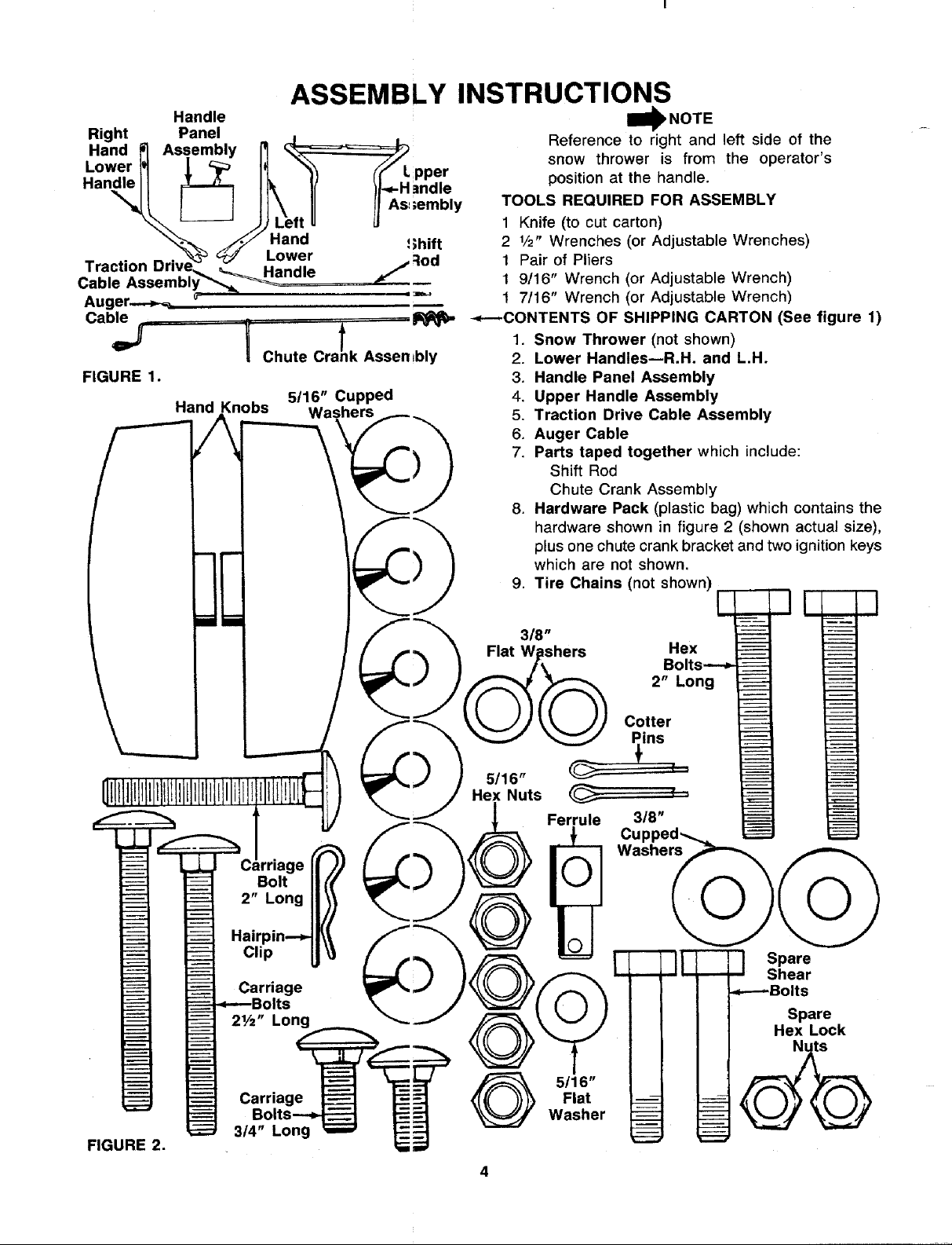
I1_ NOT E
Reference to right and left side of the
snow thrower is from the operator's
position at the handle.
TOOLS REQUIRED FOR ASSEMBLY
1 Knife (to cut carton)
2 1/2" Wrenches (or Adjustable Wrenches)
1 Pair of Pliers
1 9/16" Wrench (or Adjustable Wrench)
1 7/16" Wrench (or Adjustable Wrench)
--_---CONTENTS OF SHIPPING CARTON (See figure 1)
1. Snow Thrower (not shown)
2. Lower Handles--R.H. and L.H.
3. Handle Panel Assembly
4. Upper Handle Assembly
5. Traction Drive Cable Assembly
6. Auger Cable
7. Parts taped together which include:
Shift Rod
Chute Crank Assembly
8. Hardware Pack (plastic bag) which contains the
hardware shown in figure 2 (shown actual size),
plus one chute crank bracket and two ignition keys
which are not shown.
9. Tire Chains (not shown)
E q q
FIGURE 2.
rriage
Bolt
2" Long
Clip
Carriage
Its
21/2" Long
Carriage
3/4" Long
Flat
5/16"
Washer
2" Long
Cotter
ins
3/8"
Bolts----_
I
--LJ Spare
Shear
_---Bolts
Spare
Hex Lock
I
Upper
Chute
FIGURE 3.
Upper
Hand
Knob
5/16"
Carria
Bolt 2"
Long
FIGURE 4.
washer_ k_-..-Hand
5/16" Hex_.\ Lower
Ri
Hand
Lower
Handle
Hex Bolt 2" Long
318" d Washer
Nut _
Carriage
Bolts 21/2"
Long
Knob
5/16" Cupped
Washer
Left
Loosen
Screw
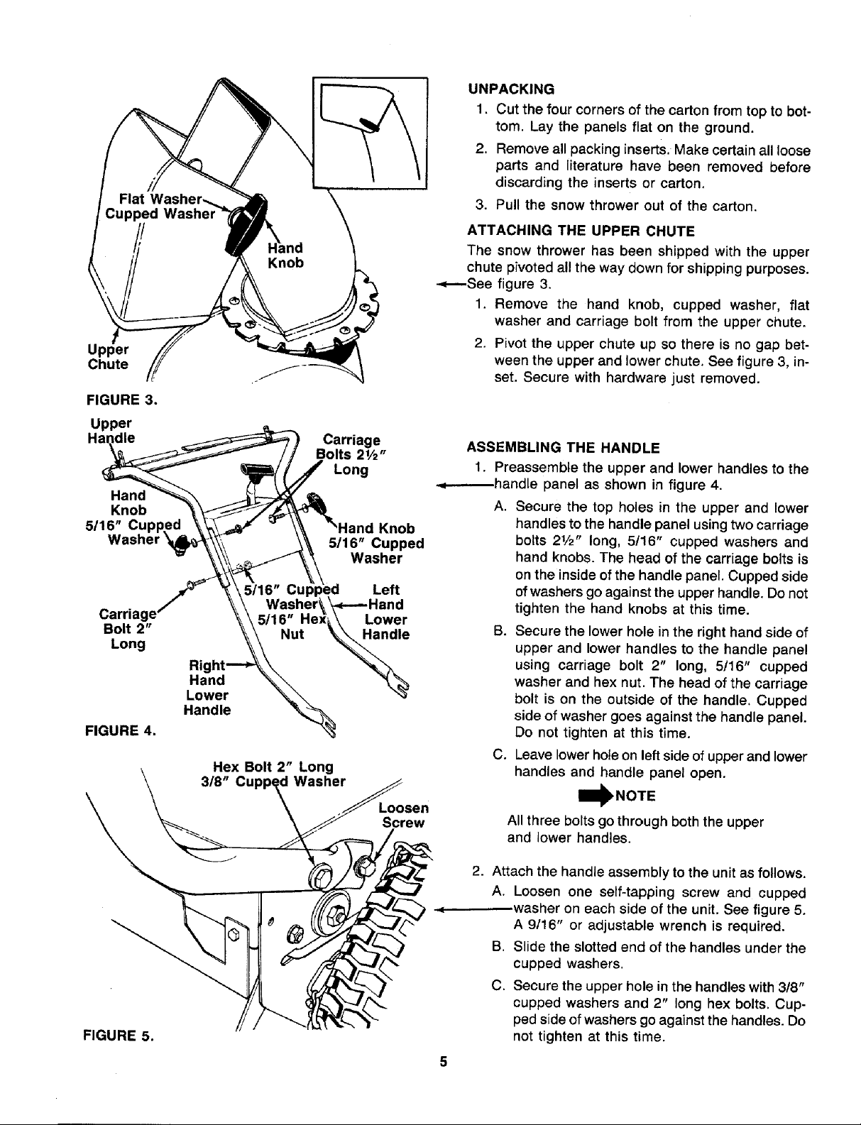
UNPACKING
1. Cut the four corners of the carton from top to bot-
tom. Lay the panels flat on the ground.
2. Remove all packing inserts. Make certain all loose
parts and literature have been removed before
discarding the inserts or carton.
3. Pull the snow thrower out of the carton.
ATTACHING THE UPPER CHUTE
The snow thrower has been shipped with the upper
chute pivoted all the way down for shipping purposes.
-.,_----See figure 3.
1, Remove the hand knob, cupped washer, fiat
washer and carriage bolt from the upper chute.
2. Pivot the upper chute up so there is no gap bet-
ween the upper and lower chute. See figure 3, in-
set. Secure with hardware just removed.
ASSEMBLING THE HANDLE
1. Preassemble the upper and lower handles to the
.d------handle panel as shown in figure 4.
A. Secure the top holes in the upper and lower
handles to the handle panel using two carriage
bolts 21/2" long, 5!16" cupped washers and
hand knobs. The head of the carriage bolts is
on the inside of the handle panel. Cupped side
of washers go against the upper handle. Do not
tighten the hand knobs at this time.
B. Secure the lower hole in the right hand side of
upper and lower handles to the handle panel
using carriage bolt 2" long, 5/16" cupped
washer and hex nut. The head of the carriage
bolt is on the outside of the handle. Cupped
side of washer goes against the handle panel.
Do not tighten at this time.
C. Leave lower hole on left side of upper and lower
handles and handle panel open.
I_NOTE
All three bolts go through both the upper
and lower handles.
FIGURE 5.
2. Attach the handle assembly to the unit as follows.
A. Loosen one self-tapping screw and cupped
.washer on each side of the unit. See figure 5.
A 9/16" or adjustable wrench is required.
B. Slide the slotted end of the handles under the
cupped washers.
C. Secure the upper hole in the handles with 318"
cupped washers and 2" long hex bolts. Cup-
ped side of washers go against the handles. Do
not tighten at this time.
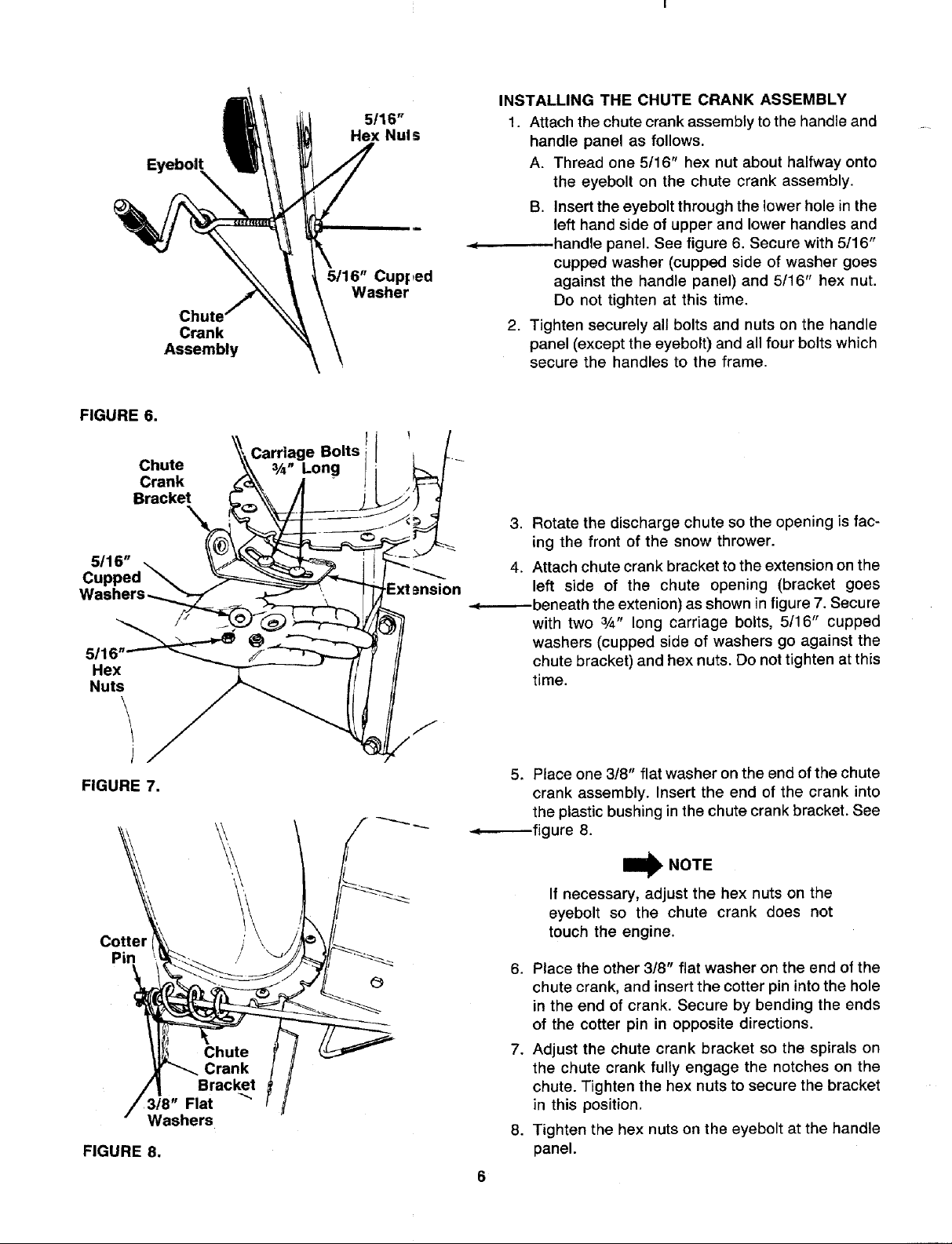
FIGURE 6.
EyeboIt
Crank
Assembly
5116"
Hex Nui s
5/16" Cupped
Washer
INSTALLING THE CHUTE CRANK ASSEMBLY
1. Attach the chute crank assembly to the handle and
handle panel as follows.
A. Thread one 5/16" hex nut about halfway onto
the eyebolt on the chute crank assembly.
B. Insert the eyebolt through the lower hole in the
left hand side of upper and lower handles and
handle panel. See figure 6. Secure with 5/16"
cupped washer (cupped side of washer goes
against the handle panel) and 5/16" hex nut.
Do not tighten at this time.
2. Tighten securely all bolts and nuts on the handle
panel (except the eyebolt) and all four bolts which
secure the handles to the frame.
Chute
Crank
Bracket
5116"
Cur
5116
Hex
Nuts
Carriage Bolts
3/_" Long
\
J
FIGURE 7.
Cotter _\ /' \ _/j_'_/_
• Washers
FIGURE 8.
3. Rotate the discharge chute so the opening is fac-
ing the front of the snow thrower.
4. Attach chute crank bracket to the extension on the
left side of the chute opening (bracket goes
-.(---_--beneath the extenion) as shown in figure 7. Secure
with two 3/4" long carriage bolts, 5116" cupped
washers (cupped side of washers go against the
chute bracket) and hex nuts. Do not tighten at this
time.
5. Place one 318" flat washer on the end of the chute
crank assembly. Insert the end of the crank into
the plastic bushing in the chute crank bracket. See
-.,_-----fig ure 8.
W NOTE
If necessary, adjust the hex nuts on the
eyebolt so the chute crank does not
touch the engine.
6. Place the other 3/8" flat washer on the end of the
chute crank, and insert the cotter pin into the hole
in the end of crank. Secure by bending the ends
of the cotter pin in opposite directions.
7. Adjust the chute crank bracket so the spirals on
the chute crank fully engage the notches on the
chute. Tighten the hex nuts to secure the bracket
in this position.
8. Tighten the hex nuts on the eyebolt at the handle
panel.
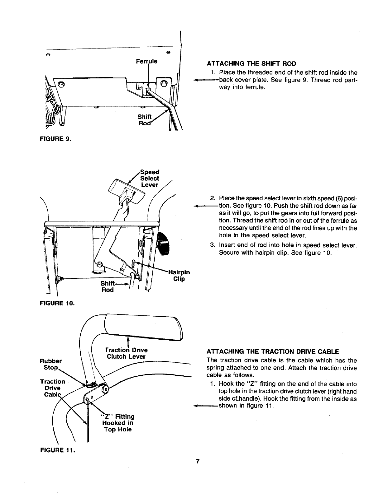
FIGURE 9.
ATTACHING THE SHIFT ROD
1. Place the threaded end of the shift rod inside the
-.q-------.-back cover plate. See figure 9. Thread rod part-
way into ferrule.
Shift
2. Place the speed select lever Lnsixthspeed (6) posi-
_tion. See figure 10. Push the shift rod down as far
as it will go, to put the gears intofull forward posi-
tion. Thread the shift rod in or out of the ferrule as
necessary until the end ofthe rod lines up with the
hole in the speed select lever.
3. Insert end of rod into hole in speed select lever.
Secure with hairpin clip. See figure 10.
FIGURE 10.
Rubber
Stop_
Traction
Drive
Cable
FIGURE 11.
Rod
Clutch Lever
"Z" Fitting
Hooked in
Top Hole
Drive
pin
Clip
ATTACHING THE TRACTION DRIVE CABLE
The traction drive cable is the cable which has the
spring attached to one end. Attach the traction drive
cable as follows.
1. Hook the "Z" fitting on the end of the cable into
top hole inthe traction drive clutch lever (righthand
side of.handle). Hook the fitting from the inside as
•._-..-----shown in figure 11.
LineUpCenter
of HookWith
Centerof Hole
FIGURE12.
Lengthl
Drive Brack _=t
Traction
Dri_!e
Cal0te
Hooke _ in
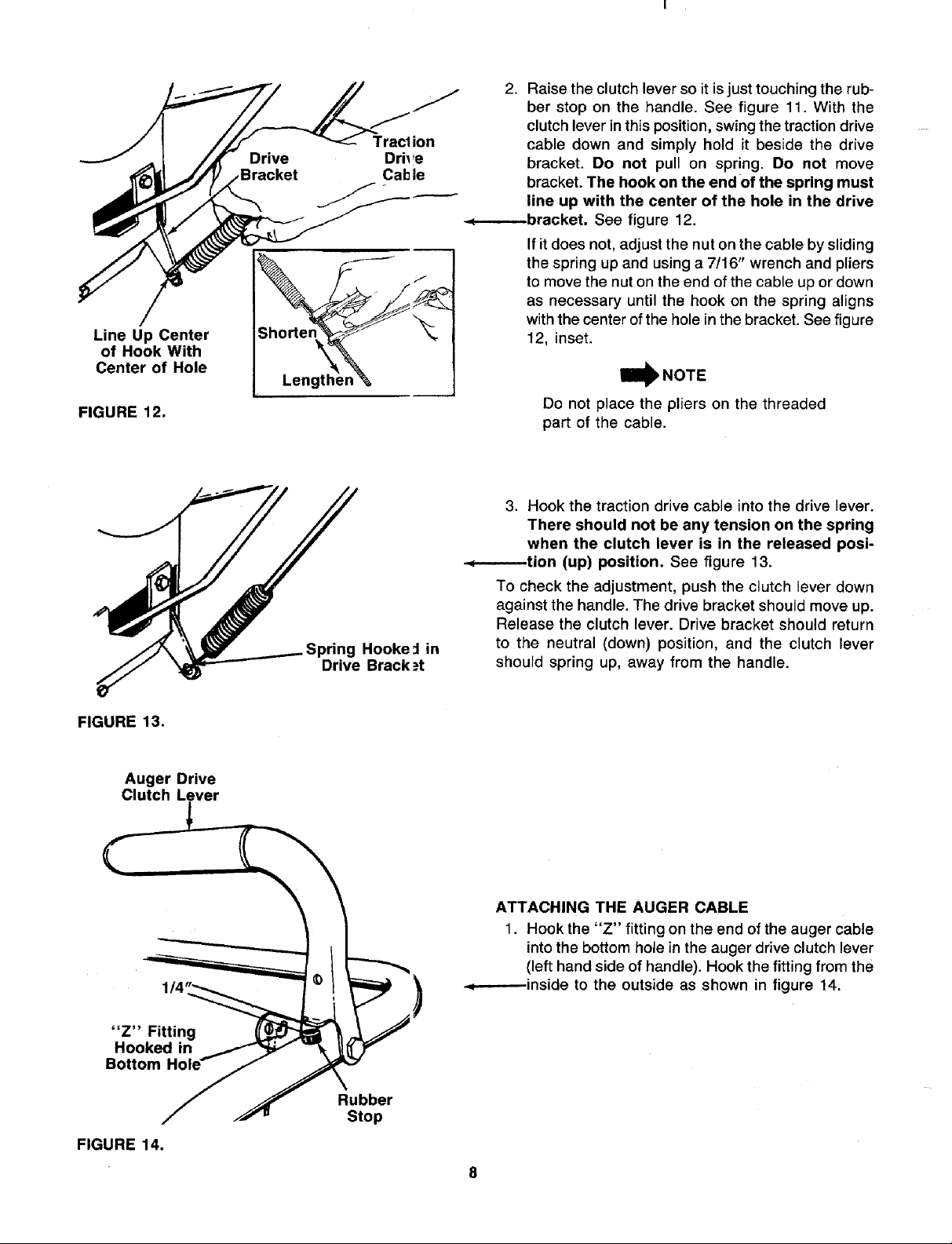
2. Raise the clutch lever so it is just touching the rub-
ber stop on the handle. See figure 11. With the
clutch lever in this position, swing the traction drive
cable down and simply hold it beside the drive
bracket. Do not pull on spring. Do not move
bracket. The hook on the end of the spring must
line up with the center of the hole in the drive
-._--.------bracket. See figure 12.
If it does not, adjust the nut on the cable by sliding
the spring up and using a 7116" wrench and pliers
to move the nut on the end of the cable up or down
as necessary until the hook on the spring aligns
with the center of the hole in the bracket. See figure
12, inset.
Do not place the pliers on the threaded
part of the cable.
3. Hook the traction drive cable into the drive lever.
There should not be any tension on the spring
when the clutch lever is in the released posi-
-.,_-_--tion (up) position. See figure 13.
To check the adjustment, push the clutch lever down
against the handle. The drive bracket should move up.
Release the clutch lever. Drive bracket should return
to the neutral (down) position, and the clutch lever
should spring up, away from the handle.
FIGURE 13.
Auger Drive
Clutch Lever
"Z" Fitting
Hooked in
Bottom
FIGURE 14.
1/4
ATTACHING THE AUGER CABLE
1. Hook the "Z" fitting on the end of the auger cable
intothe bottom hole in the auger drive clutch lever
(left hand side of handle). Hook the fitting from the
.,=----.---inside to the outside as shown in figure 14.
Rubber
Stop
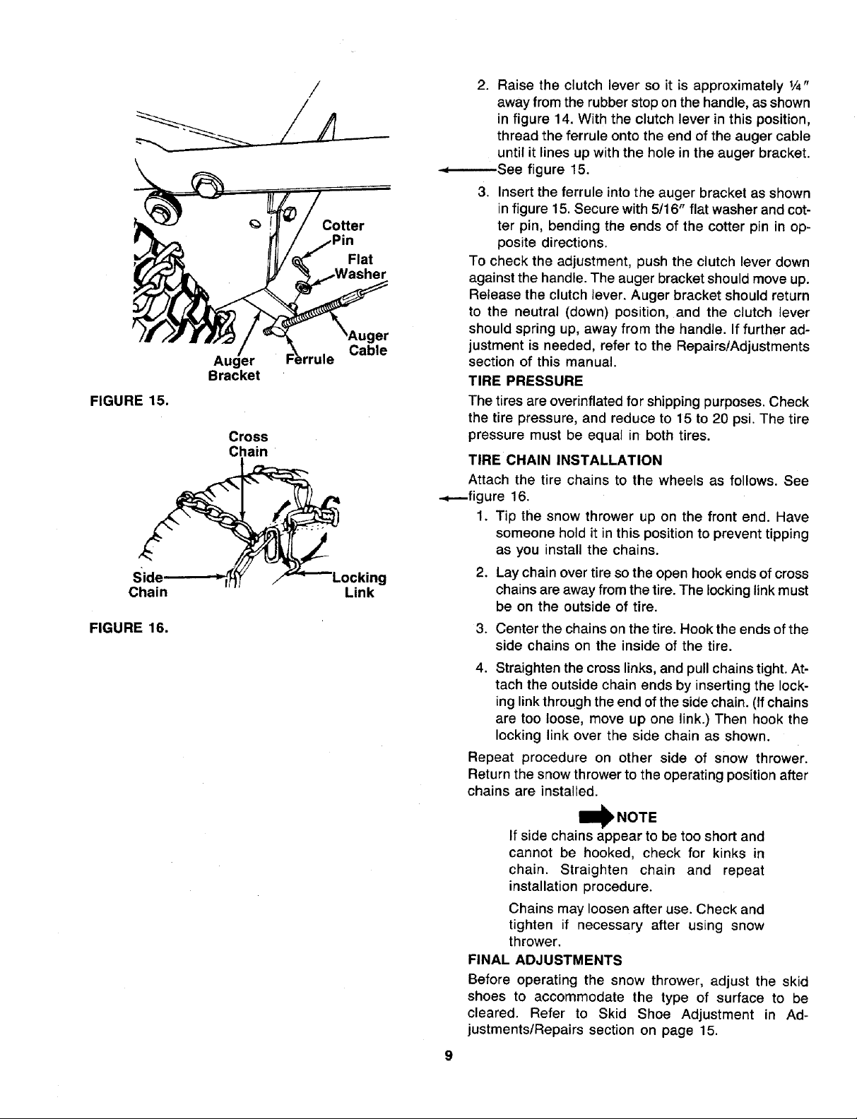
FIGURE 15.
Chain
FIGURE 16.
Auger
Bracket
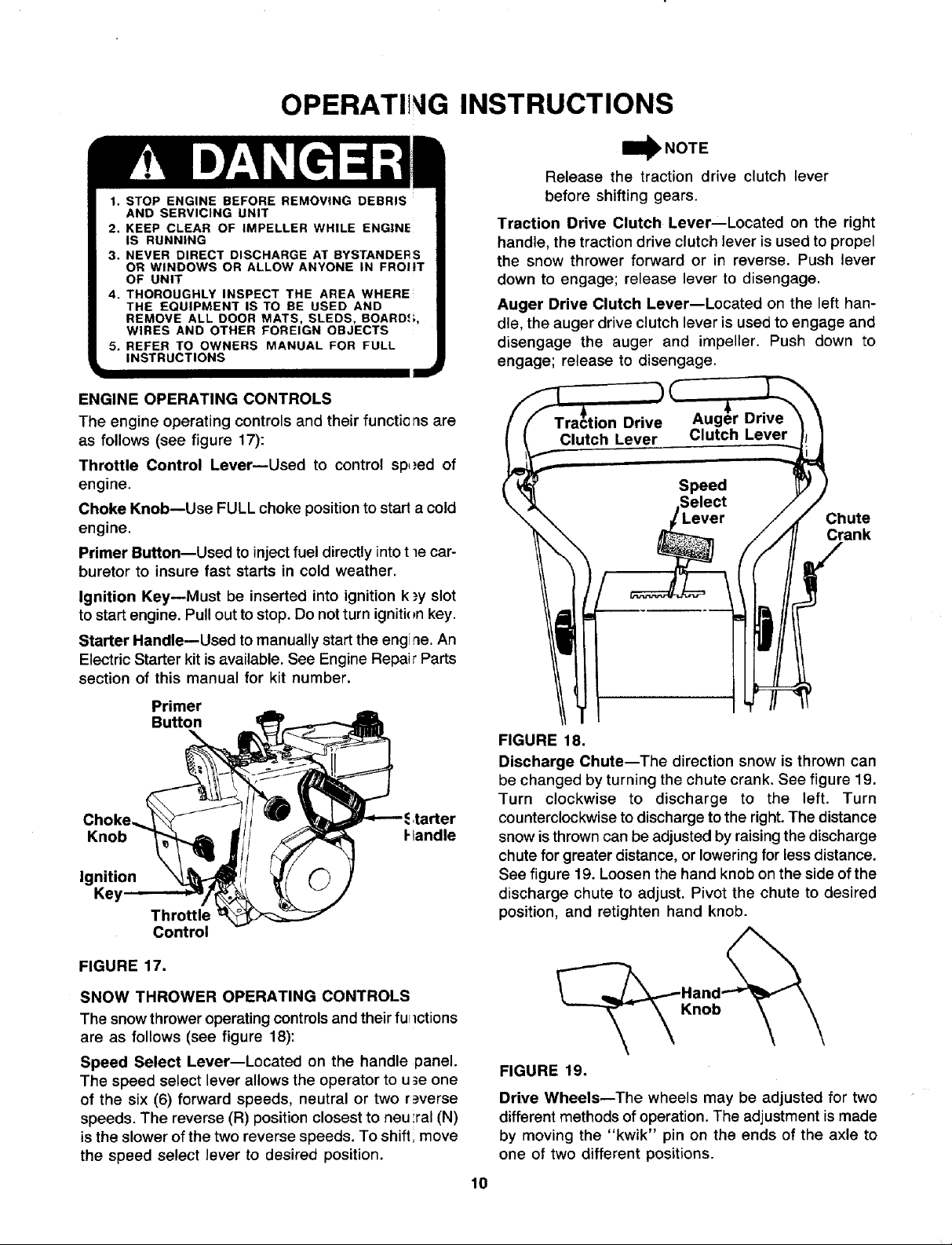
Cross
Chain
/
Cotter
Flat
Link
Cable
2. Raise the clutch lever so it is approximately 1/4"
away from the rubber stop on the handle, as shown
in figure 14. With the clutch lever in this position,
thread the ferrule onto the end of the auger cable
until it lines up with the hole in the auger bracket.
-.,--..------See figure 15.
3. Insert the ferrule into the auger bracket as shown
in figure 15. Secure with 5/16" flat washer and cot-
ter pin, bending the ends of the cotter pin in op-
posite directions.
To check the adjustment, push the clutch lever down
against the handle. The auger bracket should move up.
Release the clutch lever. Auger bracket should return
to the neutral (down) position, and the clutch lever
st
should spring up, away from the handle. If further ad-
justment is needed, refer to the Repairs/Adjustments
section of this manual.
TIRE PRESSURE
The tires are overinflated for shipping purposes. Check
the tire pressure, and reduce to 15 to 20 psi. The tire
pressure must be equal in both tires.
TIRE CHAIN INSTALLATION
Attach the tire chains to the wheels as follows. See
-+--figure 16.
1. Tip the snow thrower up on the front end. Have
someone hold it in this position to prevent tipping
as you install the chains.
2. Lay chain over tire so the open hook ends of cross
chains are away from the tire. The locking link must
be on the outside of tire.
3. Center the chains on the tire. Hook the ends of the
side chains on the inside of the tire.
4. Straighten the cross links, and pull chains tight. At-
tach the outside chain ends by inserting the lock-
ing link through the end of the side chain. (If chains
are too loose, move up one link.) Then hook the
locking link over the side chain as shown.
Repeat procedure on other side of snow thrower.
Return the snow thrower to the operating position after
chains are installed.
If side chains appear to be too short and
cannot be hooked, check for kinks in
chain. Straighten chain and repeat
installation procedure.
Chains may loosen after use. Check and
tighten if necessary after using snow
thrower.
FINAL ADJUSTMENTS
Before operating the snow thrower, adjust the skid
shoes to accommodate the type of surface to be
cleared. Refer to Skid Shoe Adjustment in Ad-
justments/Repairs section on page 15.
OPERATII G INSTRUCTIONS
1. STOP ENGINE BEFORE REMOVING DEBRIS
AND SERVICING UNIT
2. KEEP CLEAR OF IMPELLER WHILE ENGINE
IS RUNNING
3. NEVER DIRECT DISCHARGE AT BYSTANDERS
OR WINDOWS OR ALLOW ANYONE IN FROliT
OF UNIT
4. THOROUGHLY INSPECT THE AREA WHERE
THE EQUIPMENT IS TO BE USED AND
REMOVE ALL DOOR MATS, SLEDS, BOARD,*;,
WIRES AND OTHER FOREIGN OBJECTS
5. REFER TO OWNERS MANUAL FOR FULL
INSTRUCTIONS
ENGINE OPERATING CONTROLS
The engine operating controls and their functions are
as follows (see figure 17):
Throttle Control LevermUsed to control sp,_ed of
engine.
Choke Knob--Use FULL choke position to start a cold
engine.
Primer Button--Used to injectfuel directly intot le car-
buretor to insure fast starts in cold weather.
Ignition Key--Must be inserted into ignition k,_yslot
to startengine. Pullout tostop. Do notturn igniti<_nkey.
Starter Handle--Used to manually start the engine. An
Electric Starter kit is available. See Engine Repair Parts
section of this manual for kit number.
W NOTE
Release the traction drive clutch lever
before shifting gears.
Traction Drive Clutch Lever--Located on the right
handle, the traction drive clutch lever is used to propel
the snow thrower forward or in reverse. Push lever
down to engage; release lever to disengage.
Auger Drive Clutch Lever--Located on the left han-
dle, the auger drive clutch lever is used to engage and
disengage the auger and impeller. Push down to
engage; release to disengage.
Chute
Crank
Primer
Button
Knob I-tandle
Ignition
Key
Throttle
Control
FIGURE 17.
SNOW THROWER OPERATING CONTROLS
The snow thrower operating controls and their furlctions
are as follows (see figure 18):
Speed Select Lever--Located on the handle panel.
The speed select lever allows the operator to u3e one
of the six (6) forward speeds, neutral or two r_=verse
speeds. The reverse (R) position closest to neu ;ral (N)
is the slower ofthe two reverse speeds. To shift; move
the speed select lever to desired position.
FIGURE 18.
Discharge Chute--The direction snow is thrown can
be changed by turning the chute crank. See figure 19.
Turn clockwise to discharge to the left. Turn
counterclockwise to discharge to the right. The distance
snow isthrowncan be adjusted by raising the discharge
chute for greater distance, or lowering for less distance.
See figure 19. Loosen the hand knob on the side of the
discharge chute to adjust. Pivot the chute to desired
position, and retighten hand knob.
Knob
FIGURE 19.
Drive Wheels--The wheels may be adjusted for two
different methods of operation. The adjustment ismade
by moving the "kwik" pin on the ends of the axle to
one of two different positions.
10
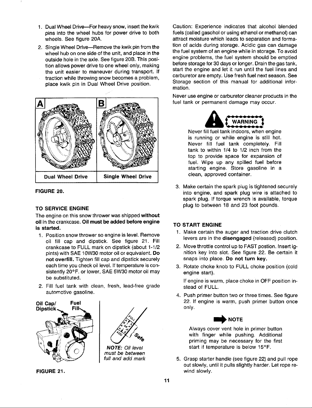
1. Dual Wheel Drive--For heavy snow, insert the kwik
pins into the wheel hubs for power drive to both
wheels. See figure 20A.
2. Single Wheel Drive--Remove the kwik pin from the
wheel hub on one side of the unit, and place in the
outside hole in the axle. See figure 20B. This posi-
tion allows power drive to one wheel only, making
the unit easier to maneuver during transport. If
traction while throwing snow becomes a problem,
place kwik pin in Dual Wheel Drive position.
Dual Wheel Drive Single Wheel Drive
Caution: Experience indicates that alcohol blended
fuels (called gasohol or using ethanol or methanol) can
attract moisture which leads to separation and forma-
tion of acids during storage. Acidic gas can damage
the fuel system of an engine while in storage. To avoid
engine problems, the fuel system should be emptied
before storage for 30 days or longer. Drain the gas tank,
start the engine and let it run until the fuel lines and
carburetor are empty. Use fresh fuel next season. See
Storage section of this manual for additional infor-
mation.
Never use engine or carburetor cleaner products in the
fuel tank or permanent damage may occur.
Never fill fuel tank indoors, when engine
is running or while engine is still hot.
Never fill fuel tank completely. Fill
tank to within 1/4 to 1/2 inch from the
top to provide space for expansion of
fuel. Wipe up any spilled fuel before
starting engine. Store gasoline in a
clean, approved container.
FIGURE 20.
TO SERVICE ENGINE
The engine on this snow thrower was shipped without
oil in the crankcase. Oil must be added before engine
is started.
1. Position snow thrower so engine is level. Remove
oil fill cap and dipstick. See figure 21. Fill
crankcase to FULL mark on dipstick (about 1-1/2
pints) with SAE 10W30 motor oil or equivalent. Do
not overfill. Tighten fill cap and dipstick securely
each time you check oil level. If temperature iscon-
sistently 20°F. or lower, SAE 5W30 motor oil may
be substituted.
2. Fill fuel tank with clean, fresh, lead-free grade
automotive gasoline.
Oil Cap/ Fuel
Dipstick._ Fill_
_rliili O (_ _
NOTE: Oil level
must be between
full and add mark
FIGURE 21.
.
Make certain the spark plug is tightened securely
into engine, and spark plug wire is attached to
spark plug. If torque wrench is available, torque
plug to between 18 and 23 foot pounds.
TO START ENGINE
1. Make certain the auger and traction drive clutch
levers are in the disengaged (released) position.
2. Move throttle control up to FAST postion. Insert ig-
nition key into slot. See figure 22. Be certain it
snaps into place. Do not turn key,
3. Rotate choke knob to FULL choke position (cold
engine start).
If engine is warm, place choke in OFF position in-
stead of FULL.
4. Push primer button two or three times. See figure
22. If engine is warm, push primer button once
only.
_)_ NOTE
Always cover vent hole in primer button
with finger while pushing. Additional
priming may be necessary for the first
start if temperature is below 15°F.
5. Grasp starter handle (see figure 22) and pull rope
out slowly, until it pulls slight!y harder. Let rope re-
wind slowly.
11
 Loading...