

Craftsman 247885570 Owner’s Manual
8_ Owner's Manual
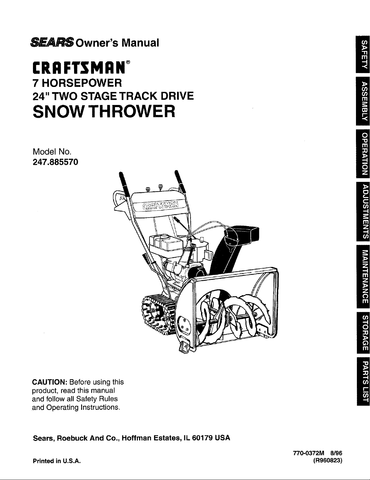
CRAFTSMAN°
7 HORSEPOWER
24" TWO STAGE TRACK DRIVE
/
SNOW THROWER
Model No.
247.885570
/
m
CAUTION: Before using this
product, read this manual
and follow all Safety Rules
and Operating Instructions.
Sears, Roebuck And Co., Hoffman Estates, IL 60179 USA
770-0372M 8/96
Printed in U.S.A. (R960823)
Warranty ..................................................................... 2
Safe Operation ........................................................... 3
Hardware Pack ........................................................... 5
Assembly .................................................................... 6
Operation .................................................................. 10
Maintenance ............................................................. 15
Service and Adjustments ......................................... 16
Off-Season Storage ................................................. 20
Trouble Shooting ...................................................... 21
Repair Parts ............................................................. 22
TWO YEAR LIMITED WARRANTY ON CRAFTSMAN SNOW THROWER
For two years from the date of purchase, when this Craftsman Snow Thrower is maintained, lubricated and tuned
up according to the instructions in the owner's manual, Sears will repair, free of charge, any defect in material and
workmanship.
If this Craftsman snow thrower is used for commercial or rental purposes, this warranty applies for only 30 days
from the date of purchase.
This warranty does not cover:
Expendable items which become worn during normal use, such as skid shoes, shave plate and spark plugs.
Repairs necessary because of operator abuse or negligence, including bent crankshafts and the failure to
maintain the equipment according to the instructions contained in the owner's manual.
WARRANTY SERVICE ISAVAILABLE BY RETURNINGTHE CRAFTSMAN SNOWTHROWER TO THE NEAREST
SEARS SERVICE CENTER/DEPARTMENT IN THE UNITED STATES.
This warranty applies only while this product is in use in the United States.
This warranty gives you specific legal rights, and you may also have other rights which may vary from state to state.
SEARS, ROEBUCK AND CO., D/817WA, HOFFMAN ESTATES, IL 60179
PRODUCT SPECIFICATIONS
Horsepower: 7 h.p.
Displacement: 15.04 cu.in.
Fuel Capacity: 4 quarts
Spark Plug J-8C or equivalent
Ignition Air Gap: .0125"
Engine MODEL 143.977001
Model Number 247.885570
Serial Number
Date of Purchase
The model and serial numbers will be found on a label
attached to the frame of the snow thrower.
You should record both serial number and date of pur-
chase and keep in a safe place for future reference.
&
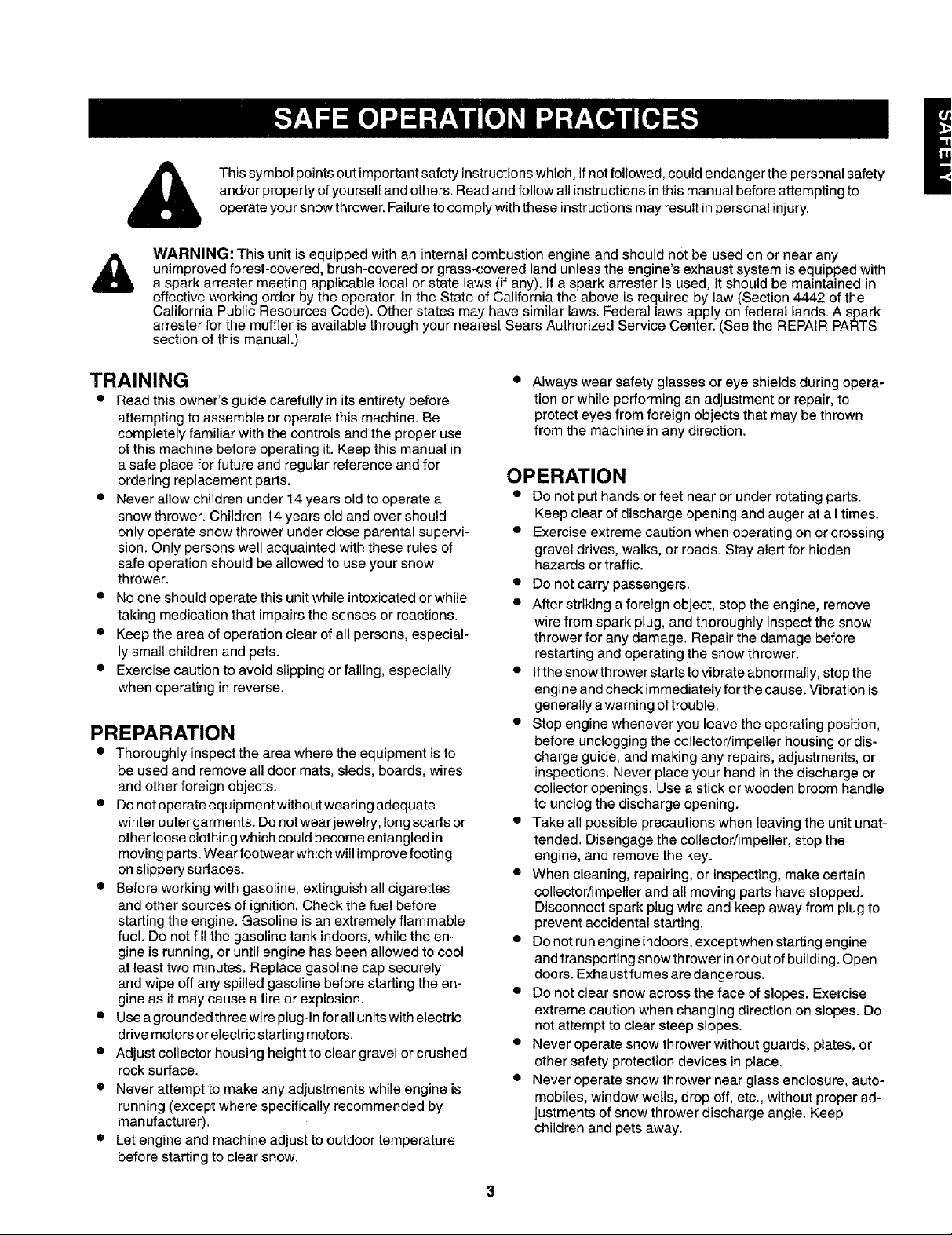
and/orpropertyofyourselfandothers.Readandfollowallinstructionsinthismanualbeforeattemptingto
Thissymbolpointsoutimportantsafetyinstructionswhich,ifnotfollowed,couldendangerthepersonalsafety
operateyoursnowthrower.Failuretocomplywiththeseinstructionsmayresultinpersonalinjury.
WARNING: This unit is equipped with an internal combustion engine and should not be used on or near any
unimproved forest-covered, brush-covered or grass-covered land unless the engine's exhaust system is equipped with
a spark arrester meeting applicable local or state laws (if any). If a spark arrester is used, it should be maintained in
effective working order by the operator. In the State of California the above is required by law (Section 4442 of the
California Public Resources Code). Other states may have similar laws. Federal laws apply on federal lands. A spark
arrester for the muffler is available through your nearest Sears Authorized Service Center. (See the REPAIR PARTS
section of this manual.)
TRAINING
• Read this owner's guide carefully in its entirety before
attempting to assemble or operate this machine. Be
completely familiar with the controls and the proper use
of this machine before operating it. Keep this manual in
a safe place for future and regular reference and for
ordering replacement parts.
• Never allow children under 14 years old to operate a
snow thrower. Children 14 years old and over should
only operate snow thrower under close parental supervi-
sion. Only persons well acquainted with these rules of
safe operation should be allowed to use your snow
thrower.
• No one should operate this unit while intoxicated or while
taking medication that impairs the senses or reactions.
• Keep the area of operation clear of all persons, especial-
ly small children and pets.
• Exercise caution to avoid slipping or falling, especially
when operating in reverse.
PREPARATION
• Thoroughly inspect the area where the equipment is to
be used and remove all door mats, sleds, boards, wires
and other foreign objects.
• Do not operate equipment without wearing adequate
winter outer garments. Do not wear jewelry, long scads or
other loose clothing which could become entangled in
moving parts. Wear footwear which will improve footing
on slippery surfaces.
• Before working with gasoline, extinguish all cigarettes
and other sources of ignition. Check the fuel before
starting the engine. Gasoline is an extremely flammable
fuel. Do not fill the gasoline tank indoors, while the en-
gine is running, or until engine has been allowed to cool
at least two minutes. Replace gasoline cap securely
and wipe off any spilled gasoline before starting the en-
gine as it may cause a fire or explosion.
• Use agroundedthree wire plug-in for all units with electric
drive motors or electric starting motors.
• Adjust collector housing height to clear gravel or crushed
rock surface.
• Never attempt to make any adjustments while engine is
running (except where specifically recommended by
manufacturer).
• Let engine and machine adjust to outdoor temperature
before starting to clear snow.
Always wear safety glasses or eye shields during opera-
tion or while performing an adjustment or repair, to
protect eyes from foreign objects that may be thrown
from the machine in any direction.
OPERATION
• Do not put hands or feet near or under rotating parts.
Keep clear of discharge opening and auger at all times.
• Exercise extreme caution when operating on or crossing
gravel drives, walks, or roads. Stay alert for hidden
hazards or traffic.
• Do not carry passengers.
• After striking aforeign object, stop the engine, remove
wire from spark plug, and thoroughly inspect the snow
thrower for any damage. Repair the damage before
restarting and operating the snow thrower.
• If the snowthrower starts to vibrate abnormally, stop the
engine and check immediately for the cause. Vibration is
generally awarning of trouble.
• Stop engine whenever you leave the operating position,
before unclogging the collector/impeller housing or dis-
charge guide, and making any repairs, adjustments, or
inspections. Never place your hand in the discharge or
collector openings. Use a stick or wooden broom handle
to unclog the discharge opening.
• Take all possible precautions when leaving the unit unat-
tended. Disengage the collector/impeller, stop the
engine, and remove the key.
• When cleaning, repairing, or inspecting, make certain
collector/impeller and all moving parts have stopped.
Disconnect spark plug wire and keep away from plug to
prevent accidental starting.
• Do not run engine indoors, except when starting engine
and transporting snow th rower in orout ofbuilding. Open
doors. Exhaust fumes are dangerous.
• Do not clear snow across the face of slopes. Exercise
extreme caution when changing direction on slopes. Do
not attempt to clear steep slopes.
• Never operate snow thrower without guards, plates, or
other safety protection devices in place.
• Never operate snow thrower near glass enclosure, auto-
mobiles, window wells, drop off, etc, without proper ad-
justments of snow thrower discharge angle. Keep
children and pets away.

NO IMAGE AVAILABLE

NO IMAGE AVAILABLE
IMPORTANT: This engine has been shipped without
gasoline or oil. After assembly, see operation section
of this manual for proper fuel and engine oil recom-
mendations.
NOTE: To determine right and left hand sides of your
snow thrower, stand behind it in the normal operating
position.
Traction Handle Panel
Handles
/!
//
// //
/ / ////
Crank
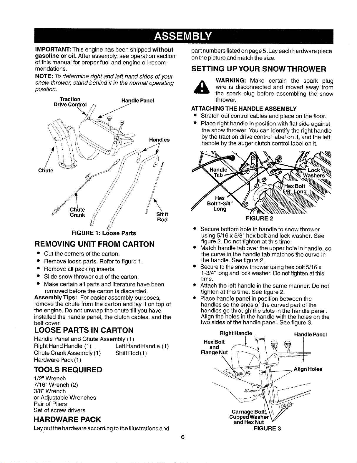
FIGURE 1: Loose Parts
Rod
REMOVING UNIT FROM CARTON
• Cut the corners of the carton.
• Remove loose parts. Refer to figure 1.
• Remove all packing inserts.
• Slide snow thrower out of the carton.
• Make certain all parts and literature have been
removed before the carton is discarded.
AssemblyTips: For easier assembly purposes,
remove the chute from the carton and lay it on top of
the engine. Do not unwrap the chute till you have
installed the handle panel, the clutch cables, and the
belt cover.
LOOSE PARTS IN CARTON
Handle Panel and Chute Assembly (1)
Right Hand Handle (1) Left Hand Handle (1)
Chute Crank Assembly (1) Shift Rod (1)
Hardware Pack (1)
TOOLS REQUIRED
1/2" Wrench
7/16" Wrench (2)
3/8" Wrench
or Adjustable Wrenches
Pair of Pliers
Set of screw drivers
HARDWARE PACK
Lay out the hardware according to the illustrationsand
part numbers listed on page 5. Lay each hardware piece
on the picture and match the size.
SETTING UPYOUR SNOWTHROWER
WARNING: Make certain the spark plug
wire is disconnected and moved away from
the spark plug before assembling the snow
thrower.
ATTACHING THE HANDLE ASSEMBLY
• Stretch out control cables and place on the floor.
• Place right handle in position with flat side against
the snow thrower. You can identify the right handle
by the traction drive control label on it, and the left
handle by the auger clutch control label on it.
Bolt 1-3/4"
Long
FIGURE 2
• Secure bottom hole in handle to snow thrower
using 5/16 x 5/8" hex bolt and lock washer. See
figure 2. Do not tighten at this time.
• Match handle tab over the upper hole in handle, so
the curve in the handle tab matches the curve in
the handle. See figure 2.
• Secure to the snow thrower using hex bolt 5/16 x
1-3/4" long and lock washer. Do not tighten at this
time.
• Attach the left handle in the same manner. Do not
tighten at this time. See figure 2.
• Place handle panel in position between the
handles so the ends of the curved part of the
handles go through the slots inthe handle panel.
Align the holes in the handle with the holes on the
two sides of the handle panel. See figure 3.
RightHandle Handle Panel
.exOo,,on°Flange I_ .....
Carriage Boltl_
Cupped Washer
and Hex Nut
FIGURE 3
• Attach handle panel to the handle with four car-
riage bolts, cupped washers (cupped side against
the handle panel) and hex nuts as shown in figure
3. Align the contour of the carriage bolt head with
the handle.
• Attach rear of handle panel with two 1/4-20 hex
bolts and flange nuts. See figure 3. Do not tighten
at this time.
• Tighten all loose hardware on the handle assembly
in the following order -- first the hex bolts at the
bottom of the handle, then the carriage bolts, and
lastly the hex bolts on the rear of the handle panel.
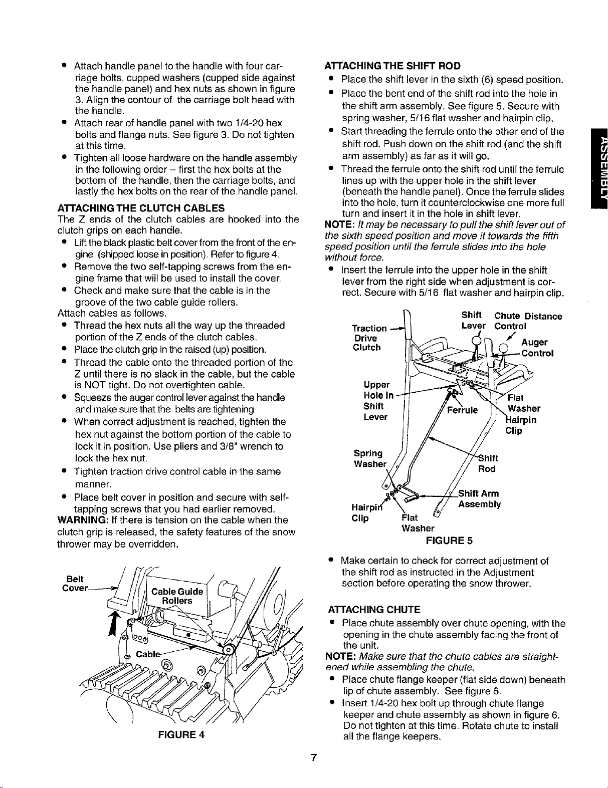
ATTACHING THE CLUTCH CABLES
The Z ends of the clutch cables are h_3okedinto the
clutch grips on each handle.
• Lift the black plastic belt cover from the front of the en-
gine (shipped loose in position). Refer to figure 4.
• Remove the two self-tapping screws from the en-
gine frame that will be used to install the cover.
• Check and make sure that the cable is in the
groove of the two cable guide rollers.
Attach cables as follows.
• Thread the hex nuts all the way up the threaded
portion of the Z ends of the clutch cables.
• Place the clutch grip in the raised (up) position.
• Thread the cable onto the threaded portion of the
Z until there is no slack in the cable, but the cable
is NOT tight. Do not overtighten cable.
• Squeeze the auger control lever against the handle
and make sure that the belts are tightening
• When correct adjustment is reached, tighten the
hex nut against the bottom portion of the cable to
lock it in position. Use pliers and 3/8" wrench to
lock the hex nut.
• Tighten traction drive control cable in the same
manner.
• Place belt cover in position and secure with self-
tapping screws that you had earlier removed.
WARNING: If there is tension on the cable when the
clutch grip is released, the safety features of the snow
thrower may be overridden.
Belt
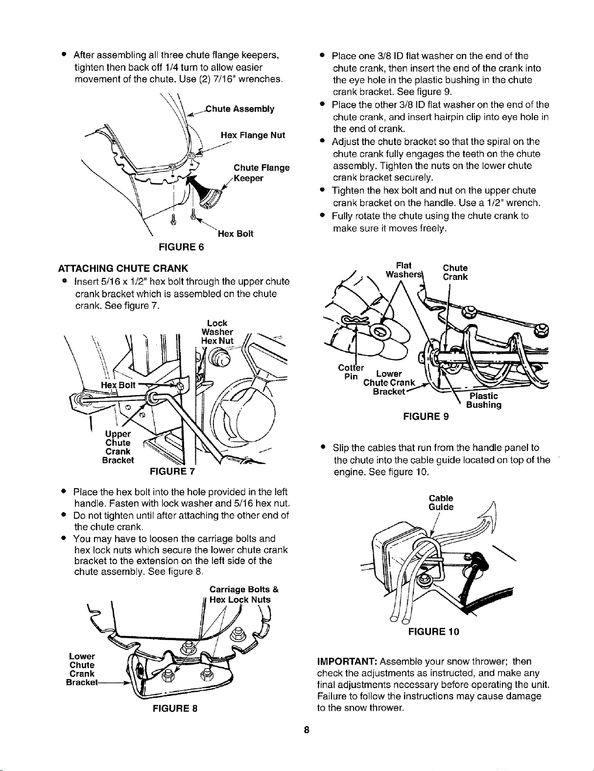
ATTACHING THE SHIFT ROD
• Place the shift lever in the sixth (6) speed position.
• Place the bent end of the shift rod into the hole in
the shift arm assembly. See figure 5. Secure with
spring washer, 5/16 flat washer and hairpin clip.
• Start threading the ferrule onto the other end of the
shift rod. Push down on the shift rod (and the shift
arm assembly) as far as it will go.
• Thread the ferrule onto the shift rod until the ferrule
lines up with the upper hole in the shift lever
(beneath the handle panel). Once the ferrule slides
into the hole, turn it counterclockwise one more full
turn and insert it in the hole in shift lever.
NOTE: It may be necessary to puff the shift lever out of
the sixth speed position and move it towards the fifth
speed position until the ferrule slides into the hole
without force.
• Insert the ferrule into the upper hole in the shift
lever from the right side when adjustment is cor-
rect. Secure with 5/16 flat washer and hairpin clip.
Shift Chute
Drive / Auger
Clutch
Traction _ Contro_
Upper
Shift I"-'F_ /!_errule_, 7Flat
Hole in ,,_Washer
Lever H _ ///_ HairpinClip
Spring / / // --i-z....
• . /! II it-'om_
Distance
ntrol
--ne j //oo0
_,_Shift Arm
Hairpir_" _" _j// Assembly
Clip Flat
• Make certain to check for correct adjustment of
the shift rod as instructed in the Adjustment
section before operating the snow thrower.
Washer
FIGURE 5
FIGURE 4
ATTACHING CHUTE
• Place chute assembly over chute opening, with the
opening in the chute assembly facing the front of
the unit.
NOTE: Make sure that the chute cables are straight-
ened while assembling the chute.
• Place chute flange keeper (flat side down) beneath
lip of chute assembly. See figure 6.
• Insert 1/4-20 hex bolt up through chute flange
keeper and chute assembly as shown in figure 6.
Do not tighten at this time. Rotate chute to install
all the flange keepers.
7
• After assembling all three chute flange keepers,
tighten then back off 1/4 turn to allow easier
movement of the chute. Use (2) 7/16" wrenches.
\ \
_Chute Assembly
Hex Flange Nut
Chute Flange
Hex Bolt
FIGURE 6
• Place one 3/8 ID flat washer on the end of the
chute crank, then insert the end of the crank into
the eye hole in the plastic bushing in the chute
crank bracket. See figure 9.
• Place the other 3/8 ID flat washer on the end of the
chute crank, and insert hairpin clip into eye hole in
the end of crank.
• Adjust the chute bracket so that the spiral on the
chute crank fully engages the teeth on the chute
assembly. Tighten the nuts on the lower chute
crank bracket securely.
• Tighten the hex bolt and nut on the upper chute
crank bracket on the handle. Use a 1/2" wrench,
• Fully rotate the chute using the chute crank to
make sure it moves freely.
ATTACHING CHUTE CRANK
• Insert 5/16 x 1/2" hex bolt through the upper chute
crank bracket which is assembled on the chute
crank. See figure 7.
Lock
Washer
Hex Nut
HexBolt
Upper
Chute
Crank
Bracket
FIGURE 7
• Place the hex bolt into the hole provided in the left
handle. Fasten with lock washer and 5/16 hex nut.
• Do not tighten until after attaching the other end of
the chute crank,
• You may have to loosen the carriage bolts and
hex lock nuts which secure the lower chute crank
bracket to the extension on the left side of the
chute assembly. See figure 8.
Flat Chute
___t__ Washers_ Crank
Pin Lower
Bracket Plastic
ChuteCra Bushing
FIGURE 9
• Slip the cables that run from the handle panel to
the chute into the cable guide located on top of the
engine. See figure 10,
Cable
Guide
Lower
Chute
Crank
FIGURE 8
Carriage Bolts &
Hex Lock Nuts
FIGURE 10
IMPORTANT: Assemble your snow thrower; then
check the adjustments as instructed, and make any
final adjustments necessary before operating the unit.
Failure to follow the instructions may cause damage
to the snow thrower.
8
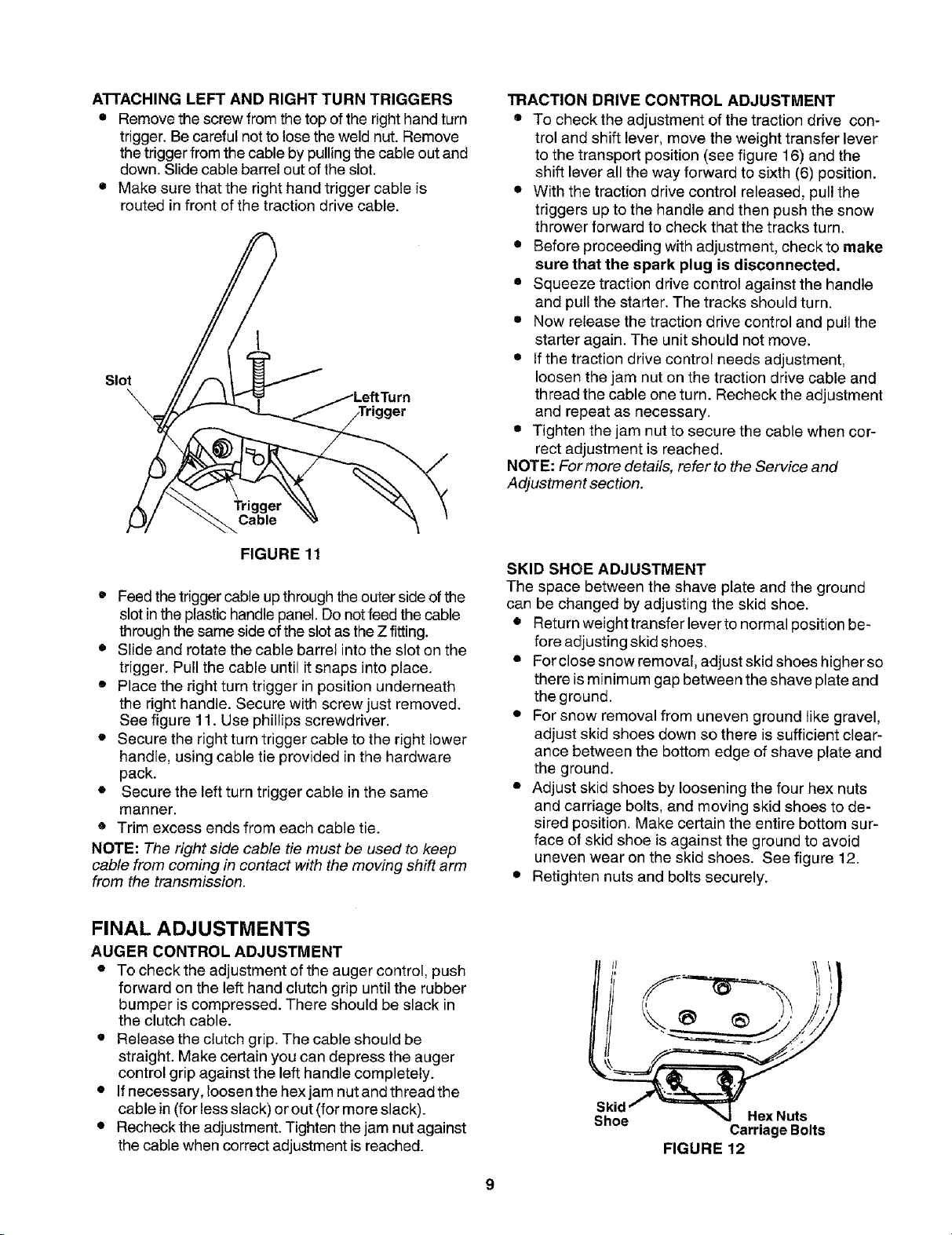
ATTACHINGLEFTANDRIGHTTURNTRIGGERS
• Remove the screw from the top of the right hand turn
trigger. Be careful not to lose the weld nut. Remove
the trigger from the cable by pulling the cable out and
down. Slide cable barrel out of the slot.
• Make sure that the right hand trigger cable is
routed in front of the traction drive cable.
I
Slot
TRACTION DRIVE CONTROL ADJUSTMENT
• To check the adjustment of the traction drive con-
trol and shift lever, move the weight transfer lever
to the transport position (see figure 16) and the
shift lever all the way forward to sixth (6) position.
• With the traction drive control released, pull the
triggers up to the handle and then push the snow
thrower forward to check that the tracks turn.
• Before proceeding with adjustment, checkto make
sure that the spark plug is disconnected.
• Squeeze traction drive control against the handle
and pull the starter. The tracks should turn.
• Now release the traction drive control and pull the
starter again. The unit should not move.
• If the traction drive control needs adjustment,
loosen the jam nut on the traction drive cable and
thread the cable one turn. Recheck the adjustment
and repeat as necessary.
• Tighten the jam nut to secure the cable when cor-
rect adjustment is reached.
NOTE: For more details, refer to the Service and
Adjustment section.
FIGURE 11
• Feed the triggercable up throughthe outer side of the
slot in the plastic handle panel. Do not feed the cable
through the same side ofthe slot as the Z fitting.
• Slide and rotate the cable barrel into the slot on the
trigger. Pull the cable until it snaps into place.
• Place the right turn trigger in position underneath
the right handle. Secure with screw just removed.
See figure 11. Use phillips screwdriver.
• Secure the right turn trigger cable to the right lower
handle, using cable tie provided in the hardware
pack.
• Secure the left turn trigger cable in the same
manner.
• Trim excess ends from each cable tie.
NOTE: The right side cable tie must be used to keep
cable from coming in contact with the moving shift arm
from the transmission.
FINAL ADJUSTMENTS
AUGER CONTROL ADJUSTMENT
• To check the adjustment of the auger control, push
forward on the left hand clutch grip until the rubber
bumper is compressed. There should be slack in
the clutch cable.
• Release the clutch grip. The cable should be
straight. Make certain you can depress the auger
control grip against the left handle completely.
• If necessary, loosen the hex jam nut and th read the
cable in (for less slack) or out (for more slack).
• Recheck the adjustment. Tighten the jam nut against
the cable when correct adjustment is reached.
SKID SHOE ADJUSTMENT
The space between the shave plate and the ground
can be changed by adjusting the skid shoe.
• Return weight transfer lever to normal position be-
fore adjusting skid shoes.
• For close snow removal, adjust skid shoes higher so
there is minimum gap between the shave plate and
the ground.
• For snow removal from uneven ground like gravel,
adjust skid shoes down so there is sufficient clear-
ance between the bottom edge of shave plate and
the ground.
• Adjust skid shoes by loosening the four hex nuts
and carriage bolts, and moving skid shoes to de-
sired position. Make certain the entire bottom sur-
face of skid shoe is against the ground to avoid
uneven wear on the skid shoes. See figure 12.
• Retighten nuts and bolts securely.
Skid
Shoe
FIGURE 12
Hex Nuts
Carriage Bolts
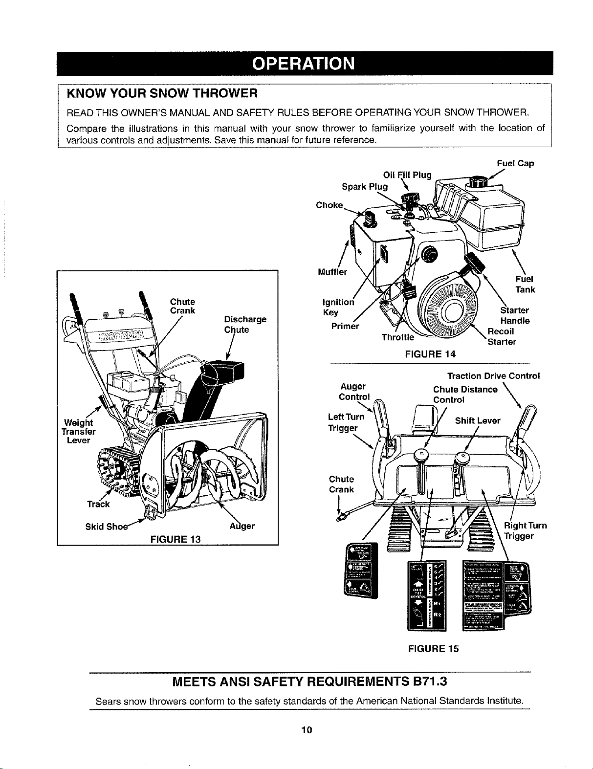
KNOW YOUR SNOW THROWER
READ THIS OWNER'S MANUAL AND SAFETY RULES BEFORE OPERATING YOUR SNOW THROWER.
Compare the illustrations in this manual with your snow thrower to familiarize yourself with the location of
various controls and adjustments. Save this manual for future reference.
Fuel Cap
Oil Fill Plug
Spark Plug
Weight
Transfer
Lever
Skid
Chute
Crank
FIGURE 13
Discharge
Chute
/
A_ger
Muffler
Ig
Key Starter
Primer Handle
Throttle
FIGURE 14
Traction Drive Control
Auger Chute Distance \
Control Control
LeftTurn Shift Lever
Trigger
Chute
Crank
Recoil
\
Right Turn
Trigger
\
Fuel
Tank
FIGURE 15
MEETS ANSI SAFETY REQUIREMENTS B71.3
Sears snow throwers conform to the safety standards of the American National Standards Institute.
10
The operation of any snow thrower can result in foreign objects being thrown into the eyes, which
can result in severe eye damage. Always wear safety glasses or eye shields while operating the
snow thrower or performing any adjustments or repairs. We recommend standard safety glasses
or wide vision safety mask for over your glasses available at SEARS retail stores.
OPERATION CONTROLS
CHUTE CRANK
The chute crank is located on left hand side of the
snow thrower. See figure 13.To change the direction in
which snow is thrown, turn chute crank as follows: turn
clockwise to discharge to the left; turn counterclock-
wise to discharge to the right.
THROTTLE CONTROL
The throttle control is located on the engine. It
regulates the speed of the engine. See figure 14.
SAFETY IGNITION SWITCH
The ignition key must be inserted into the switch for
the unit to start. Remove the ignition key when snow
thrower is not in use. See figure 14.
LEFT AND RIGHT TURN TRIGGER
The left and right turn triggers are located on the
underside of the handles and are used to assist in
steering your snow thrower. See figure 15. Squeeze
the right turn trigger when turning right, squeeze the
left turn trigger when turning left. Operate your snow
thrower in open areas until you become familiar with
these controls.
SHIFT LEVER
The shift lever is located in the center of the handle
panel. The shift lever may be moved into one of eight
positions. Use the shift lever to determine ground
speed. Forward---one of six speeds; position one (1) is
the slowest and position six (6) isthe fastest.
Reverse--two reverse (R) speeds; R2 is faster.
engaged with the traction drive control engaged, you
can release the auger control (on the left handle) and
the augers will remain engaged. Release the traction
drive control to stop both the augers and wheel drive.
(Auger control must also be released).
CHUTE DISTANCE CONTROL
The distance snow is thrown can be adjusted by
adjusting the angle of the chute assembly. Move the
chute distance control forward to decrease the dis-
tance, toward the rear to increase the distance. See
figure 15.
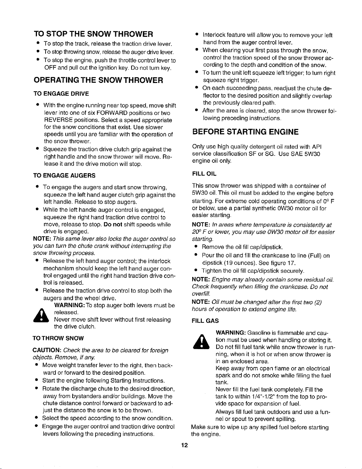
WEIGHT TRANSFER LEVER
The weight transfer lever is located on the right side of
the snow thrower and is used to select the position of
the housing and the method of track operation. Move
the lever to the right, then forward or backward to one
of the three positions. See figure 16.
Transport--Raises the front end of the snow
thrower for easy transport. Using proper caution,
this position may also be used on many gravel drive-
ways to clear snow while leaving gravel undisturbed.
Normal Snow--Allows the tracks to be suspended
independently for continuous ground contact.
Packed Snow--Locks the front end of the snow
thrower down to the ground for hard-packed or icy
snow conditions.
AUGER CONTROL
The auger control is located on the left handle. See
figure 15. Squeeze the auger control against the
handle to engage the augers; release to disengage
the augers. (Traction drive control must also be
released.)
TRACTION DRIVE CONTROL
The traction drive control is located on the right han-
dle. Squeeze the traction drive control to engage the
track drive; release to stop. See figure 15.
This same lever also locks the auger control so
you can turn the chute crank without interrupting
the snow throwing process. If the auger control is
Position
Normal
Snow
Position
FIGURE 16
11
TO STOP THE SNOW THROWER
• To stop the track, release the traction drive lever.
• To stop throwing snow, release the auger drive lever.
• To stop the engine, push the throttle control lever to
OFF and pull out the ignition key. Do not turn key.
OPERATING THE SNOW THROWER
TO ENGAGE DRIVE
• With the engine running near top speed, move shift
lever into one of six FORWARD positions or two
REVERSE positions. Select a speed appropriate
for the snow conditions that exist. Use slower
speeds until you are familiar with the operation of
the snow thrower.
• Squeeze the traction drive clutch grip against the
right handle and the snow thrower will move. Re-
lease it and the drive motion will stop.
TO ENGAGE AUGERS
• Interlock feature will allow you to remove your left
hand from the auger control lever.
• When clearing your first pass through the snow,
control the traction speed of the snow thrower ac-
cording to the depth and condition of the snow.
• To turn the unit left squeeze left trigger; to turn right
squeeze right trigger.
• On each succeeding pass, readjust the chute de-
flector to the desired position and slightly overlap
the previously cleared path.
• After the area is cleared, stop the snow thrower fol-
lowing preceding instructions.
BEFORE STARTING ENGINE
Only use high quality detergent oil rated with API
service classification SF or SG. Use SAE 5W30
engine oil only.
FILL OIL
• To engage the augers and start snow throwing,
squeeze the left hand auger clutch grip against the
left handle. Release to stop augers.
• While the left handle auger control is engaged,
squeeze the right hand traction drive control to
move, release to stop. Do not shift speeds while
drive is engaged.
NOTE: This same lever also locks the auger control so
you can turn the chute crank without interrupting the
snow throwing process.
• Release the left hand auger control; the interlock
mechanism should keep the left hand auger con-
trol engaged until the right hand traction drive con-
trol is released.
• Release the traction drive control to stop both the
augers and the wheel drive.
WARNING: To stop auger both levers must be
_ released.
TO THROW SNOW
CAUTION: Check the area to be cleared for foreign
objects. Remove, if any.
• Move weight transfer lever to the right, then back-
• Start the engine following Starting Instructions.
• Rotate the discharge chute to the desired direction,
• Select the speed according to the snow condition.
• Engage the auger control and traction drive control
Never move shift lever without first releasing
the drive clutch.
ward or forward to the desired position.
away from bystanders and/or buildings. Move the
chute distance control forward or backward to ad-
just the distance the snow is to be thrown.
levers following the preceding instructions.
This snow thrower was shipped with a container of
5W30 oil. This oil must be added to the engine before
starting. For extreme cold operating conditions of 0° F
or below, use a partial synthetic 0W30 motor oil for
easier starting.
NOTE: In areas where temperature is consistently at
20 ° F or lower, you may use OW30 motor off for easier
starting.
• Remove the oil fill cap/dipstick.
• Pour the oil and fill the crankcase to line (Full) on
dipstick (19 ounces). See figure 17.
• Tighten the oil fill cap/dipstick securely.
NOTE: Engine may already contain some residual oil.
Check frequently when filling the crankcase. Do not
overfill.
NOTE: Oil must be changed after the first two (2)
hours of operation to extend engine life.
FILL GAS
WARNING: Gasoline is flammable and cau-
tion must be used when handling or storing it.
Do not fill fuel tank while snow thrower is run-
ning, when it is hot or when snow thrower is
in an enclosed area.
Keep away from open flame or an electrical
spark and do not smoke while filling the fuel
tank.
Never fill the fuel tank completely. Fill the
tank to within 1/4"-1/2" from the top to pro-
vide space for expansion of fuel.
Always fill fuel tank outdoors and use a fun-
nel or spout to prevent spilling.
Make sure to wipe up any spilled fuel before starting
the engine.
12
Storegasolineinaclean,approvedcontainer,and
keepthecapinplaceonthecontainer.
• Make sure that the container from which you pour
the gasoline is clean and free from rust or other
foreign particles.
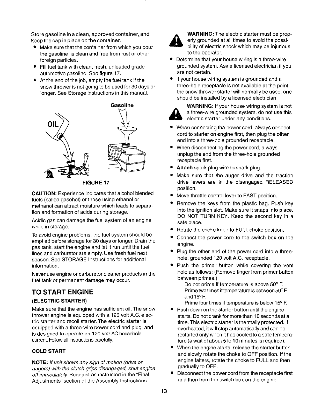
• Fill fuel tank with clean, fresh, unleaded grade
automotive gasoline. See figure 17.
• At the end of the job, empty the fuel tank if the
snow thrower is not going to be used for 30 days or
longer. See Storage instructions in this manual.
Gasoline
OIL
FIGURE 17
CAUTION: Experience indicates that alcohol blended
fuels (called gasohol) or those using ethanol or
methanol can attract moisture which leads to separa-
tion and formation of acids during storage.
Acidic gas can damage the fuel system of an engine
while in storage.
To avoid engine problems, the fuel system should be
emptied before storage for 30 days or longer. Drain the
gas tank, start the engine and let it run until the fuel
lines and carburetor are empty. Use fresh fuel next
season. See STORAGE Instructions for additional
information.
Never use engine or carburetor cleaner products in the
fuel tank or permanent damage may occur.
TO START ENGINE
(ELECTRIC STARTER)
Make sure that the engine has sufficient oil. The snow
thrower engine is equipped with a 120 volt A.C. elec-
tric starter and recoil starter. The electric starter is
equipped with a three-wire power cord and plug, and
is designed to operate on 120 volt AC household
current. Follow all instructions carefully.
COLD START
NOTE: If unit shows any sign of motion (drive or
augers) with the clutch grips disengaged, shut engine
off immediately. Readjust as instructed in the "Final
Adjustments" section of the Assembly Instructions.
erly grounded at all times to avoid the possi-
WARNING: The electric starter must be prop-
bility of electric shock which may be injurious
to the operator.
• Determine that your house wiring is a three-wire
grounded system. Ask a licensed electrician if you
are not certain.
• If your house wiring system is grounded and a
three-hole receptacle is not available at the point
the snow thrower starter will normally be used, one
should be installed by a licensed electrician.
WARNING: If your house wiring system is not
a three-wire grounded system, do not use this
electric starter under any conditions.
• When connecting the power cord, always connect
cord to starter on engine first, then plug the other
end into a three-hole grounded receptacle.
• When disconnecting the power cord, always
unplug the end from the three-hole grounded
receptacle first.
• Attach spark plug wire to spark plug.
• Make sure that the auger drive and the traction
drive levers are in the disengaged RELEASED
position.
• Move throttle control lever to FAST position.
• Remove the keys from the plastic bag. Push key
into the ignition slot. Make sure it snaps into place.
DO NOT TURN KEY. Keep the second key in a
safe place.
• Rotate the choke knob to FULL choke position.
• Connect the power cord to the switch box on the
engine.
• Plug the other end of the power cord into a three-
hole, grounded 120 volt A.C. receptacle.
• Push the primer button while covering the vent
hole as follows: (Remove finger from primer button
between primes.)
Do not prime if temperature is above 50o E
Prime two times if temperature is between 50° F
and 15° E
Prime four times if temperature is below 15° E
• Push down on the starter button until the engine
starts. Do not crank for more than 10 seconds at a
time. This electric starter isthermally protected. If
overheated, it will stop automatically and can be
restarted only when it has cooled to a safe tempera-
ture (a wait of about 5 to 10 minutes is required).
• When the engine starts, release the starter button
and slowly rotate the choke to OFF position. If the
engine falters, rotate the choke to FULL and then
gradually to OFF.
• Disconnect the power cord from the receptacle first
and then from the switch box on the engine.
13
• Allow the engine to warm up for a few minutes be-
cause the engine will not develop full power until it
reaches operating temperature.
• Operate the engine at full throttle (FAST) when
throwing snow.
WARM START
• If restarting a warm engine after a shut down, ro-
tate choke to OFF instead of FULL and do not
push the primer button.
WARM START
• If restarting a warm engine after a shut down, ro-
tate choke to OFF instead of FULL and do not
push the primer button.
TO START ENGINE
(RECOIL STARTER)
Make sure that the engine has sufficient oil and the
auger drive and the traction drive levers are disen-
gaged (released).
• Move throttle control to FAST position.
• Push key into the ignition slot and make sure that it
snaps into place. Do not turn key. Remove plastic
bag and keep the second key in a safe place.
• Rotate choke control to FULL choke position.
• Push the primer button while covering the vent hole.
Remove finger from primer button between primes.
Do not prime if temperature is above 50° E
Prime two times in temperatures between 50° F
and 15° F.
Prime four times in temperatures below 15° E
• Pull the starter handle rapidly. Do not allow the
handle to snap back, but allow it to rewind slowly
while keeping a firm hold on the starter handle.
• As the engine warms up and begins to operate
evenly, rotate the choke knob slowly to OFF posi-
tion. if the engine falters, return to FULL choke,
then slowly move to OFF choke position.
• Allow the engine to warm up for a few minutes be-
cause the engine wil! not develop full power until it
reaches operating temperature.
• Operate the engine at full throttle (FAST) when
throwing snow.
FROZEN RECOIL STARTER
If the starter is frozen and will not turn the engine, pro-
ceed as follows:
• Pull as much rope out of the starter as possible.
• Release the starter handle and let it snap back
against the starter.
• If the engine still fails to start, repeat the first two
steps. If continued attempts do not free starter,
follow the electric starter procedures to start.
Avoid possible freezing of recoil starter and the engine
controls.
OPERATING TIPS
NOTE: Allow the engine to warm up for a few minutes
as the engine will not develop full power until it
reaches operating temperature.
Warning: Temperature of muffler and
surrounding areas may exceed 150° E Avoid
these areas.
• For most efficient snow removal, remove snow
immediately after it falls.
• Discharge snow downwind whenever possible.
Slightly overlap each previous swath.
• Set the skid shoes 1/4" below the scraper bar for
normal usage. The skid shoes may be adjusted
upward for hard-packed snow. Adjust downward
when using on gravel or crushed rock.
• Follow the precautions listed under "To Stop
Engine" and "Frozen Recoil Starter" to prevent
possible freeze-up.
• Clean the snow thrower thoroughly after each use.
14
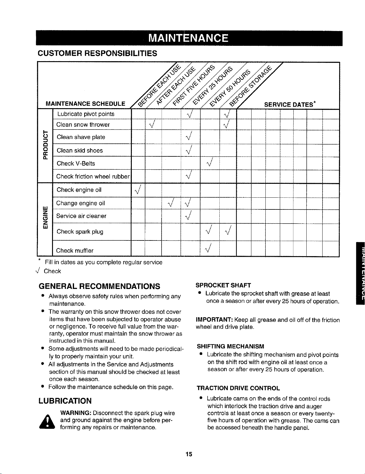
CUSTOMER RESPONSIBILITIES
MAINTENANCE SCHEDULE
Lubricate pivot points
Clean snow thrower
I,.-
O Clean shave plate
8
Clean skid shoes
n
Check V-Belts
Check friction wheel rubber
Check engine oil
Change engine oil
W
Z
Service air cleaner
z
= Check spark plug _/ %/
Check muffler _/
* Fill in dates as you complete regular service
_/ Check
I ]J J
[
i
,
J
DATES*
GENERAL RECOMMENDATIONS
• Always observe safety rules when performing any
maintenance.
• The warranty on this snow thrower does not cover
items that have been subjected to operator abuse
or negligence. To receive full value from the war-
ranty, operator must maintain the snow thrower as
instructed in this manual.
• Some adjustments will need to be made periodical-
ly to properly maintain your unit.
• All adjustments in the Service and Adjustments
section of this manual should be checked at least
once each season.
• Follow the maintenance schedule on this page.
LUBRICATION
WARNING: Disconnect the spark plug wire
and ground against the engine before per-
forming any repairs or maintenance.
SPROCKET SHAFT
• Lubricate the sprocket shaft with grease at least
once a season or after every 25 hours of operation.
IMPORTANT: Keep all grease and oil off of the friction
wheel and drive plate.
SHIFTING MECHANISM
• Lubricate the shifting mechanism and pivot points
on the shift rod with engine oil at least once a
season or after every 25 hours of operation.
TRACTION DRIVE CONTROL
Lubricate cams on the ends of the control rods
which interlock the traction drive and auger
controls at least once a season or every twenty-
five hours of operation with grease. The cams can
be accessed beneath the handle panel.
15
GEAR CASE
CHECK V-BELTS
• The gear case is lubricated with grease at the
factory and does not require checking. If
disassembled for any reason, lubricate with 2
ounces of Shell Alvania grease.
BEARINGS
• Lubricate the auger bearings, wheel bearings and
the bearings on the side of the frame once a
season with light oil.
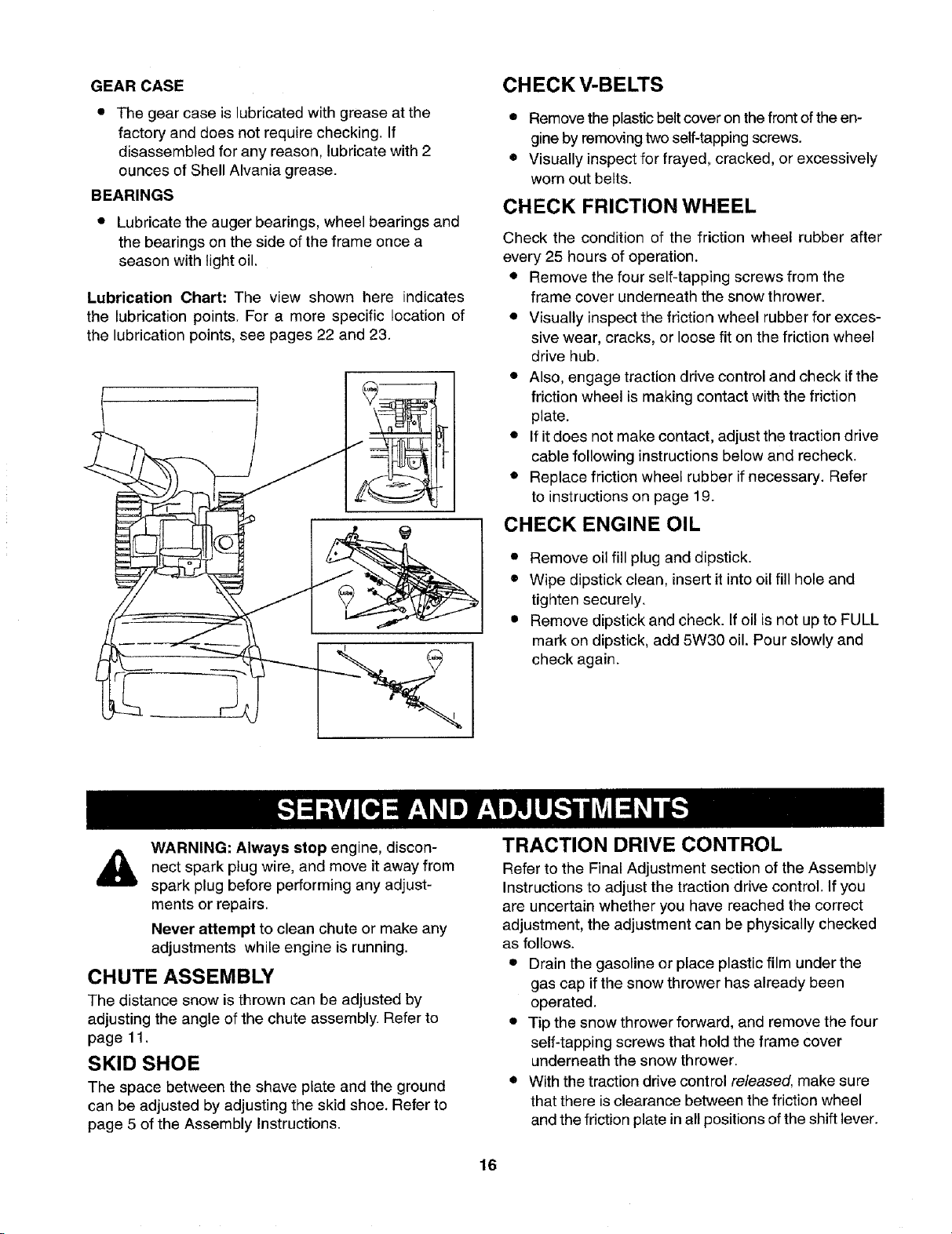
Lubrication Chart: The view shown here indicates
the lubrication points. For a more specific location of
the lubrication points, see pages 22 and 23.
• Remove the plastic belt cover on the front of the en-
gine by removing two self-tapping screws.
• Visually inspect for frayed, cracked, or excessively
worn out belts.
CHECK FRICTION WHEEL
Check the condition of the friction wheel rubber after
every 25 hours of operation.
• Remove the four self-tapping screws from the
frame cover underneath the snow thrower.
• Visually inspect the friction wheel rubber for exces-
sive wear, cracks, or loose fit on the friction wheel
drive hub.
• Also, engage traction drive control and check if the
friction wheel is making contact with the friction
plate.
• If it does not make contact, adjust the traction drive
cable following instructions below and recheck.
• Replace friction wheel rubber if necessary. Refer
to instructions on page 19.
CHECK ENGINE OIL
• Remove oil fill plug and dipstick.
• Wipe dipstick clean, insert it into oil fill hole and
tighten securely.
• Remove dipstick and check. If oil is not up to FULL
mark on dipstick, add 5W30 oil. Pour slowly and
check again.
WARNING: Always stop engine, discon-
spark plug away
nect wire, and move it from
spark plug before performing any adjust-
ments or repairs.
Never attempt to clean chute or make any
adjustments while engine is running.
CHUTE ASSEMBLY
The distance snow is thrown can be adjusted by
adjusting the angle of the chute assembly. Refer to
page 11.
SKID SHOE
The space between the shave plate and the ground
can be adjusted by adjusting the skid shoe. Refer to
page 5 of the Assembly Instructions.
TRACTION DRIVE CONTROL
Refer to the Final Adjustment section of the Assembly
Instructions to adjust the traction drive control. If you
are uncertain whether you have reached the correct
adjustment, the adjustment can be physically checked
as follows.
• Drain the gasoline or place plastic film under the
gas cap if the snow thrower has already been
operated.
• Tip the snow thrower forward, and remove the four
self-tapping screws that hold the frame cover
underneath the snow thrower.
• With the traction drive control released, make sure
that there is clearance between the friction wheel
and the friction plate in all positions of the shift lever.
16
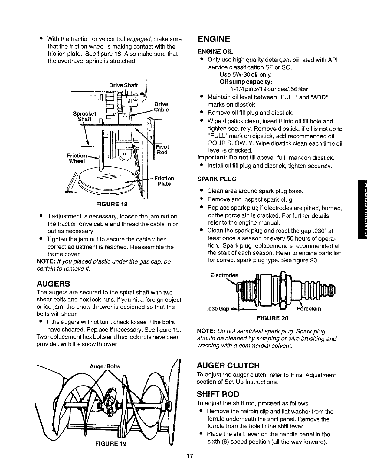
• With the traction drive control engaged, make sure
that the friction wheel is making contact with the
friction plate. See figure 18. Also make sure that
the overtravel spring is stretched.
Drive Shaft
Drive
Sprocket
Shaft
Pivot
Rod
Wheel
ENGINE
ENGINE OIL
• Only use high quality detergent oil rated with API
service classification SF or SG.
Use 5W-30 oil.only.
Oil sump capacity:
1-1/4 pints/19 ounces/.56 liter
• Maintain oil level between "FULL" and "ADD"
marks on dipstick.
• Remove oil fill plug and dipstick.
• Wipe dipstick clean, insert it into oil fill hole and
tighten securely. Remove dipstick. If oil is not up to
"FULL" mark on dipstick, add recommended oil.
POUR SLOWLY. Wipe dipstick clean each time oil
level is checked,
Important: Do not fill above "full" mark on dipstick.
• Install oil fill plug and dipstick, tighten securely.
Friction
Plate
FIGURE 18
• if adjustment is necessary, loosen the jam nut on
the traction drive cable and thread the cable in or
out as necessary.
• Tighten the jam nut to secure the cable when
correct adjustment is reached. Reassemble the
frame cover.
NOTE: If you placed plastic under the gas cap, be
certain to remove it.
AUGERS
The augers are secured to the spiral shaft with two
shear bolts and hex lock nuts. If you hit a foreign object
or ice jam, the snow thrower is designed so that the
bolts will shear.
• If the augers will not turn, check to see ifthe bolts
have sheared. Replace if necessary. See figure 19.
Two replacement hex bolts and hex lock nuts have been
provided with the snow thrower.
SPARK PLUG
• Clean area around spark plug base.
• Remove and inspect spark plug.
• Replace spark plug if electrodes are pitted, burned,
or the porcelain is cracked. For further details,
refer to the engine manual.
• Clean the spark plug and reset the gap .030" at
least once a season or every 50 hours of opera-
tion. Spark plug replacement is recommended at
the start of each season. Refer to engine parts list
for correct spark plug type. See figure 20.
Electrodes
.030 Gal
FIGURE 20
NOTE: Do not sandblast spark plug. Spark ptug
should be cleaned by scraping or wire brushing and
washing with a commercial solvent.
Auger Bolts
FIGURE 19
AUGER CLUTCH
To adjust the auger clutch, refer to Final Adjustment
section of Set-Up Instructions.
SHIFT ROD
To adjust the shift rod, proceed as follows.
• Remove the hairpin clip and flat washer from the
ferrule underneath the shift panel. Remove the
ferrule from the hole inthe shift lever.
• Place the shift lever on the handle panel in the
sixth (6) speed position (all the way forward).
17
• Push down on the shift rod (and shift arm assem-
bly) as far as it will go. Hold it in this position.
• Thread the ferrule up or down the shift rod as
necessary until the ferrule lines up with the upper
hole in the shift lever. Refer to figure 9.
• Insert ferrule into the upper hole in the shift lever
from the right side when adjustment is correct.
Secure with flat washer and hairpin clip.
• Before operating the snow thrower, check for cor-
rect adjustment of the traction drive control as in-
structed in the Final Adjustment section.
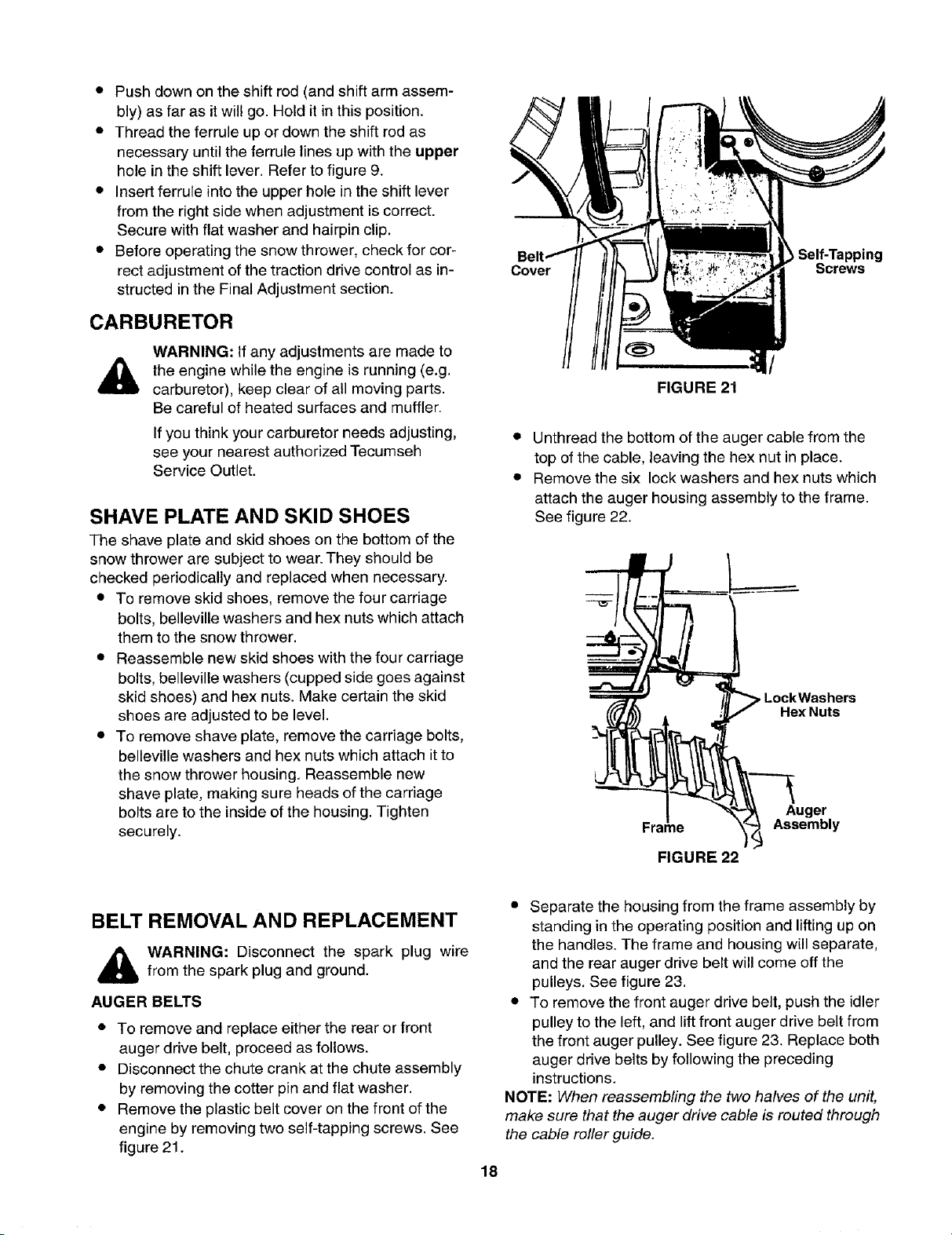
CARBURETOR
Cover Screws
Self-Tapping
WARNING: If any adjustments are made to
the engine while the engine is running (e.g.
carburetor), keep clear of all moving parts.
Be careful of heated surfaces and muffler.
If you think your carburetor needs adjusting,
see your nearest authorized Tecumseh
Service Outlet.
SHAVE PLATE AND SKID SHOES
The shave plate and skid shoes on the bottom of the
snow thrower are subject to wear. They should be
checked periodically and replaced when necessary.
• To remove skid shoes, remove the four carriage
bolts, belleville washers and hex nuts which attach
them to the snow thrower.
• Reassemble new skid shoes with the four carriage
bolts, belleville washers (cupped side goes against
skid shoes) and hex nuts. Make certain the skid
shoes are adjusted to be level.
• To remove shave plate, remove the carriage bolts,
belleville washers and hex nuts which attach it to
the snow thrower housing. Reassemble new
shave plate, making sure heads of the carriage
bolts are to the inside of the housing. Tighten
securely.
/
FIGURE 21
• Unthread the bottom of the auger cable from the
top of the cable, leaving the hex nut in place.
• Remove the six lock washers and hex nuts which
attach the auger housing assembly to the frame.
See figure 22.
pLockWashers
Hex Nuts
Auger
Frame
FIGURE 22
Assembly
BELT REMOVAL AND REPLACEMENT
,_ WARNING: Disconnect the spark plug wire
AUGER BELTS
• To remove and replace either the rear or front
• Disconnect the chute crank at the chute assembly
• Remove the plastic belt cover on the front of the
from the spark plug and ground.
auger drive belt, proceed as follows.
by removing the cotter pin and flat washer.
engine by removing two self-tapping screws. See
figure 21.
• Separate the housing from the frame assembly by
standing in the operating position and lifting up on
the handles. The frame and housing will separate,
and the rear auger drive belt will come off the
pulleys. See figure 23.
• To remove the front auger drive belt, push the idler
pulley to the left, and lift front auger drive belt from
the front auger pulley. See figure 23. Replace both
auger drive belts by following the preceding
instructions.
NOTE: When reassembling the two halves of the unit,
make sure that the auger drive cable is routed through
the cable roller guide.
18
 Loading...