

Page 1
Operator's Manual
CRRFr MRN
24" SNOW THROWER
Model No. 247.881731
,, SAFETY
o ASSEMBLY
OPERATION
MAINTENANCE
CAUTION" Before using this
product, read this manual and
follow all safety rules and operating
instructions.
Sears Brands Management Corporation, Hoffman Estates, IL 60179, U.S.A.
Visit our website: www.craftsman.com FormI/o 769-081740
PARTS LIST
o ESPANOL
(June21,2013)
Page 2
WarrantyStatement.............................. Page2
SafeOperationPractices...................... Pages3-6
Assembly.................................... Pages8-11
Operation.................................. Pages12-15
Service&Maintenance...................... Pages16-22
CRAFTSMANTWOYEARFULLWARRANTY
FORTWOYEARSfromthedateofpurchase,thisproductiswarrantedagainstanydefectsinmaterialorworkmanship.Defectiveproductwillreceivefree
repairorfreereplacementif repairisunavailable.
ADDITIONALLIFETIMELIMITEDWARRANTYon UPPERand LOWERCHUTE
FORASLONGASITISUSEDbytheoriginalownerafterthesecondyearfromthedateofpurchase,theupperandlowerchuteofthissnowthrowerare
warrantedagainstanydefectsinmaterialorworkmanshipasverifiedbyaSearsauthorizedserviceprovider.Withproofofpurchase,youwill receiveanew
chutefreeofcharge.Youareresponsibleforthelaborcostofinstallationandanycostincurredtoverifythedefect.
Forwarrantycoveragedetailstoobtainrepairorreplacement,visitthewebsite:www.craftsman.com
ThiswarrantycoversONLYdefectsinmaterialandworkmanship.WarrantycoveragedoesNOTinclude:
• Expendableitemsthatcanwearoutfromnormalusewithinthewarrantyperiod,includingbutnotlimitedto augers,augerpaddles,drift cutters,skid
shoes,shaveplate,shearpins,sparkplug,aircleaner,belts,andoilfilter.
Off-SeasonStorage............................. Page23
Troubleshooting............................... Page24
PartsList................................... Pages26-43
RepairProtectionAgreement................... Page46
Espa_ol......................................... Page47
• Standardmaintenanceservicing,oilchanges,ortune-ups.
• Tirereplacementorrepaircausedbypuncturesfromoutsideobjects,suchasnails,thorns,stumps,orglass.
• Tireorwheelreplacementorrepairresultingfromnormalwear,accident,orimproperoperationormaintenance.
• Repairsnecessarybecauseofoperatorabuse,includingbutnotlimitedtodamagecausedbyover-speedingtheengine,orfromimpactingobjectsthat
bendtheframe,augershaft,etc.
• Repairsnecessarybecauseofoperatornegligence,includingbutnotlimitedto,electricalandmechanicaldamagecausedbyimproperstorage,failureto
usethepropergradeandamountofengineoil,orfailuretomaintaintheequipmentaccordingtotheinstructionscontainedintheoperator'smanual.
• Engine(fuelsystem)cleaningorrepairscausedbyfueldeterminedtobecontaminatedoroxidized(stale).Ingeneral,fuelshouldbeusedwithin30days
ofitspurchasedate.
• Normaldeteriorationandwearoftheexteriorfinishes,orproductlabelreplacement.
Thiswarrantyisvoidifthisproductiseverusedwhileprovidingcommercialservicesorifrentedto anotherperson.
Thiswarrantygivesyouspecificlegalrights,andyoumayalsohaveotherrightswhichvaryfromstatetostate.
SearsBrandsManagementCorporation,NoffmanEstates,IL60179
Engine Oil: 5W-30
Fuel: Unleaded Gasoline
Engine: MTD
Model Number
Serial Number
Date of Purchase
Record the model number, serial number,
and date of purchase above.
© Sears Brands, LLC 2
Page 3
Thissymbolpointsout importantsafety instructionswhich,ifnot
followed,couldendangerthe personalsafetyand/orproperty of
yourselfandothers.Readandfollow all instructionsinthis manual
beforeattempting to operatethis machine.Failureto complywith these
instructionsmayresultinpersonalinjury.Whenyouseethis symbol,HEED
ITSWARNING!
Thismachinewasbuilt to beoperatedaccordingtothesafeoperation
practicesinthismanual.Aswith anytype of powerequipment,
carelessnessorerroronthe part ofthe operatorcanresultinseriousinjury.
Thismachineiscapableof amputatingfingers, hands,toesandfeet and
throwingdebris.Failuretoobservethefollowing safety instructionscould
resultinseriousinjuryor death.
CALIFORNIA PROPOSITION 65
EngineExhaust,someofits constituents,and certainvehiclecomponents
containor emit chemicalsknownto Stateof Californiatocausecancerand
birth defectsorother reproductiveharm.
TRAINING
Read,understand,andfollowall instructionsonthemachineandinthe
manual(s)beforeattemptingtoassembleandoperate.Failuretodosocan
resultinseriousinjurytotheoperatorand/orbystanders.Keepthis manual
inasafeplaceforfutureandregularreferenceandfororderingreplacement
parts.
Befamiliarwith allcontrolsandtheirproperoperation.Knowhowtostop
themachineanddisengagethemquickly.
Neverallowchildrenunder14yearsof agetooperatethismachine.Children
14andovershouldreadandunderstandtheinstructionsandsafeoperation
practicesinthismanualandonthemachineandbetrainedandsupervised
byanadult.
Neverallowadultsto operatethismachinewithout properinstruction.
Thrownobjectscancauseseriouspersonalinjury.Planyoursnow-throwing
patterntoavoiddischargeofmaterialtowardroads,bystandersandthelike.
Keepbystanders,petsandchildrenatleast75feetfromthemachinewhileit
isin operation.Stopmachineif anyoneentersthearea.
Exercisecautiontoavoidslippingorfalling,especiallywhenoperatingin
reverse.
PREPARATION
Thoroughlyinspecttheareawheretheequipmentistobeused.Removeall
doormats,newspapers,sleds,boards,wiresandotherforeignobjects,which
couldbetrippedoverorthrownbytheauger/impeller.
Alwayswearsafetyglassesoreyeshieldsduringoperationandwhile
performinganadjustmentor repairtoprotectyoureyes.Thrownobjects
whichricochetcancauseseriousinjurytotheeyes.
Donotoperatewithout wearingadequatewinteroutergarments.Donot
wearjewelry,longscarvesorotherlooseclothing,whichcouldbecome
entangledinmovingparts.Wearfootwearwhichwill improvefootingon
slipperysurfaces.
Useagroundedthree-wireextensioncordandreceptacleforallmachines
with electricstartengines.
Your Responsibility--Restrict theuseof this powermachineto
personswhoread,understandandfollow thewarningsandinstructionsin
thismanualandonthe machine.
SAVETHESEINSTRUCTIONS!
Disengageallcontrolleversbeforestartingtheengine.
Adjustcollectorhousingheighttocleargravelorcrushedrocksurfaces.
Neverattempttomakeanyadjustmentswhileengineisrunning,except
wherespecificallyrecommendedintheoperator'smanual.
Letengineandmachineadjusttooutdoortemperaturebeforestartingto
clearsnow.
Safe Handling of Gasoline:
Toavoidpersonalinjuryor propertydamageuseextremecareinhandling
gasoline.Gasolineisextremely flammableandthe vaporsareexplosive.
Seriouspersonalinjurycanoccurwhengasolineisspilledonyourselforyour
clotheswhichcanignite.Washyourskinandchangeclothesimmediately.
Useonlyanapprovedgasolinecontainer.
Neverfill containersinsidea vehicleoronatruckortrailerbedwitha plastic
liner.Alwaysplacecontainersonthegroundawayfromyourvehiclebefore
filling.
Whenpractical,removegas-poweredequipmentfromthetruckor
trailerandrefuelitontheground.Ifthisis notpossible,thenrefuelsuch
equipmentonatrailerwith aportablecontainer,ratherthanfromagasoline
dispensernozzle.
Keepthenozzleincontactwith therimofthefueltankorcontaineropening
atalltimesuntilfuelingiscomplete.Donotuseanozzlelock-opendevice.
Extinguishallcigarettes,cigars,pipesandothersourcesof ignition.
Neverfuelmachineindoors.
Neverremovegascaporaddfuelwhiletheengineishotorrunning.Allow
enginetocoolatleasttwominutesbeforerefueling.
Neveroverfill fueltank.Filltankto nomorethan1/2inchbelowbottomof
fillernecktoallowspacefor fuelexpansion.
Replacegasolinecapandtightensecurely.
Ifgasolineisspilled,wipeit offthe engineandequipment.Moveunitto
anotherarea.Wait.5minutesbeforestartingtheengine.
Page 4
Toreducefirehazards,keepmachinefreeofgrass,leaves,orotherdebris
build-up.Cleanupoilorfuelspillageandremoveanyfuelsoakeddebris.
Neverstorethemachineorfuelcontainerinsidewherethereisanopen
flame,sparkorpilotlightasonawaterheater,spaceheater,furnace,clothes
dryerorothergasappliances.
OPERATION
Donotputhandsorfeetnearrotatingparts,intheauger/impellerhousing
orchuteassembly.Contactwith therotatingpartscanamputatehandsand
feet.
Theauger/impellercontrolleverisasafetydevice.Neverbypassits
operation.Doingsomakesthemachineunsafeandmaycausepersonal
injury.
Thecontrolleversmustoperateeasilyin bothdirectionsandautomatically
returntothedisengagedpositionwhenreleased.
Neveroperatewith amissingordamagedchuteassembly.Keepallsafety
devicesinplaceandworking.
Neverrunanengineindoorsor inapoorlyventilatedarea.Engineexhaust
containscarbonmonoxide,anodorlessanddeadlygas.
Donotoperatemachinewhileundertheinfluenceofalcoholordrugs.
Mufflerandenginebecomehotandcancauseaburn.Donottouch.Keep
childrenaway.
Exerciseextremecautionwhenoperatingonorcrossinggravelsurfaces.Stay
alertforhiddenhazardsortraffic.
Exercisecautionwhenchangingdirectionandwhileoperatingonslopes.Do
notoperateonsteepslopes.
Planyoursnow-throwingpatterntoavoiddischargetowardswindows,
walls,carsetc.Thus,avoidingpossiblepropertydamageorpersonalinjury
causedbyaricochet.
Neverdirectdischargeatchildren,bystandersandpetsor allowanyonein
frontofthemachine.
Donotoverloadmachinecapacitybyattemptingtoclearsnowattoofastof
arate.
Neveroperatethismachinewithoutgoodvisibilityorlight.Alwaysbesureof
yourfootingandkeepafirmholdonthehandles.Walk,neverrun.
Disengagepowertotheauger/impellerwhentransportingornotin use.
Neveroperatemachineathightransportspeedsonslipperysurfaces.Look
downandbehindandusecarewhenbackingup.
Ifthemachineshouldstartto vibrateabnormally,stoptheengine,
disconnectthesparkplugwire andgrounditagainsttheengine.Inspect
thoroughlyfordamage.Repairanydamagebeforestartingandoperating.
Disengageallcontrolleversandstopenginebeforeyouleavetheoperating
position(behindthehandles).Waituntil theauger/impellercomesto
acompletestopbeforeuncloggingthechuteassembly,makingany
adjustments,orinspections.
Neverputyourhandin thedischargeorcollectoropenings.Donotunclog
chuteassemblywhileengineisrunning.Shutoff engineandremainbehind
handlesuntilallmovingpartshavestoppedbeforeunclogging.
Useonlyattachmentsandaccessoriesapprovedbythemanufacturer(e.g.
wheelweights,tirechains,cabsetc.).
Whenstartingengine,pull cordslowlyuntilresistanceisfelt,thenpull
rapidly.Rapidretractionofstartercord(kickback)will pullhandandarm
towardenginefasterthanyoucanletgo.Brokenbones,fractures,bruisesor
sprainscouldresult.
Ifsituationsoccurwhicharenotcoveredinthismanual,usecareandgood
judgment.
CLEARING A CLOGGED DISCHARGE CHUTE
Handcontactwith therotatingimpellerinsidethedischargechuteisthemost
commoncauseofinjuryassociatedwith snowthrowers.Neveruseyourhandto
cleanoutthedischargechute.
Toclearthechute:
a. SHUTTHEENGINEOFF!
b. Wait10secondsto besuretheimpellerbladeshavestopped
rotating.
c. Alwaysuseaclean-outtool,notyourhands.
MAINTENANCE & STORAGE
Nevertamperwith safetydevices.Checktheirproperoperationregularly.
Referto themaintenanceandadjustmentsectionsofthismanual.
Beforecleaning,repairing,orinspectingmachinedisengageallcontrol
leversandstoptheengine.Waituntiltheauger/impellercometoacomplete
stop.Disconnectthesparkplugwireandgroundagainsttheengineto
preventunintendedstarting.
Checkboltsandscrewsforpropertightnessatfrequentintervalsto keepthe
machineinsafeworkingcondition.Also,visuallyinspectmachineforany
damage.
Donotchangetheenginegovernorsettingorover-speedtheengine.The
governorcontrolsthemaximumsafeoperatingspeedof theengine.
Snowthrowershaveplatesandskidshoesaresubjecttowearanddamage.
Foryoursafetyprotection,frequentlycheckallcomponentsandreplace
with originalequipmentmanufacturer's(OEM)partsonlyaslistedinthe
Partspagesofthisoperator'smanual.Useofpartswhichdonotmeetthe
originalequipmentspecificationsmayleadtoimproperperformanceand
compromisesafety!
Checkcontrolleversperiodicallyto verifytheyengageanddisengage
properlyandadjust,if necessary.Refertotheadjustmentsectioninthis
operator'smanualforinstructions.
Maintainorreplacesafetyandinstructionlabels,asnecessary.
Observeproperdisposallawsandregulationsforgas,oil,etc.toprotectthe
environment.
Priortostoring,runmachineafewminutestoclearsnowfrommachineand
preventfreezeupof auger/impeller.
Neverstorethemachineorfuelcontainerinsidewherethereisanopen
flame,sparkorpilotlight suchasawaterheater,furnace,clothesdryeretc.
Alwaysrefertotheoperator'smanualforproperinstructionsonoff-season
storage.
4
Page 5
Checkfuelline,tank,cap,andfittingsfrequentlyfor cracksor leaks.Replace
if necessary.
Donotcrankenginewith sparkplugremoved.
AccordingtotheConsumerProductsSafetyCommission(CPSC)andthe
U.S.EnvironmentalProtectionAgency(EPA),thisproducthasanAverage
Useful Lifeof seven(7)years,or60hoursofoperation.Attheendof
theAverage Useful Lifehavethemachineinspectedannuallybyan
authorizedservicedealerto ensurethat allmechanicalandsafetysystems
areworkingproperlyandnotwornexcessively.Failuretodosocanresultin
accidents,injuriesordeath.
DO NOT MODIFY ENGINE
Toavoidseriousinjuryordeath,donotmodifyengineinanyway.Tampering
with the governorsetting canleadto arunawayengineandcauseit to
operateat unsafespeeds.Nevertamperwith factorysetting ofengine
governor.
NOTICE REGARDING EMiSSiONS
Engineswhichare certifiedto complywith Californiaandfederal EPA
emissionregulationsfor SORE(SmallOffRoadEquipment)arecertified
tooperateonregularunleadedgasoline,and mayincludethefollowing
emissioncontrolsystems:EngineModification (EM),OxidizingCatalyst(0C),
SecondaryAirinjection(SAI)andThreeWayCatalyst(TWC)ifsoequipped.
SPARK ARRESTOR
e
Thismachineisequippedwith aninternalcombustionengineandshould
not beusedonornearanyunimprovedforest-covered,brushcoveredor
grass-coveredland unlessthe engine'sexhaustsystemisequippedwith a
sparkarrestormeetingapplicablelocalorstatelaws(if any).
Ira sparkarrestorisused,it shouldbemaintainedineffective working order
bythe operator.IntheState ofCaliforniathe aboveisrequired bylaw (Section
4442ofthe CaliforniaPublicResourcesCode).Otherstates mayhavesimilar
laws.Federallawsapplyonfederal lands.
Asparkarrestorfor the muffler isavailablethroughyournearestSearsParts
andRepairServiceCenter.
Page 6
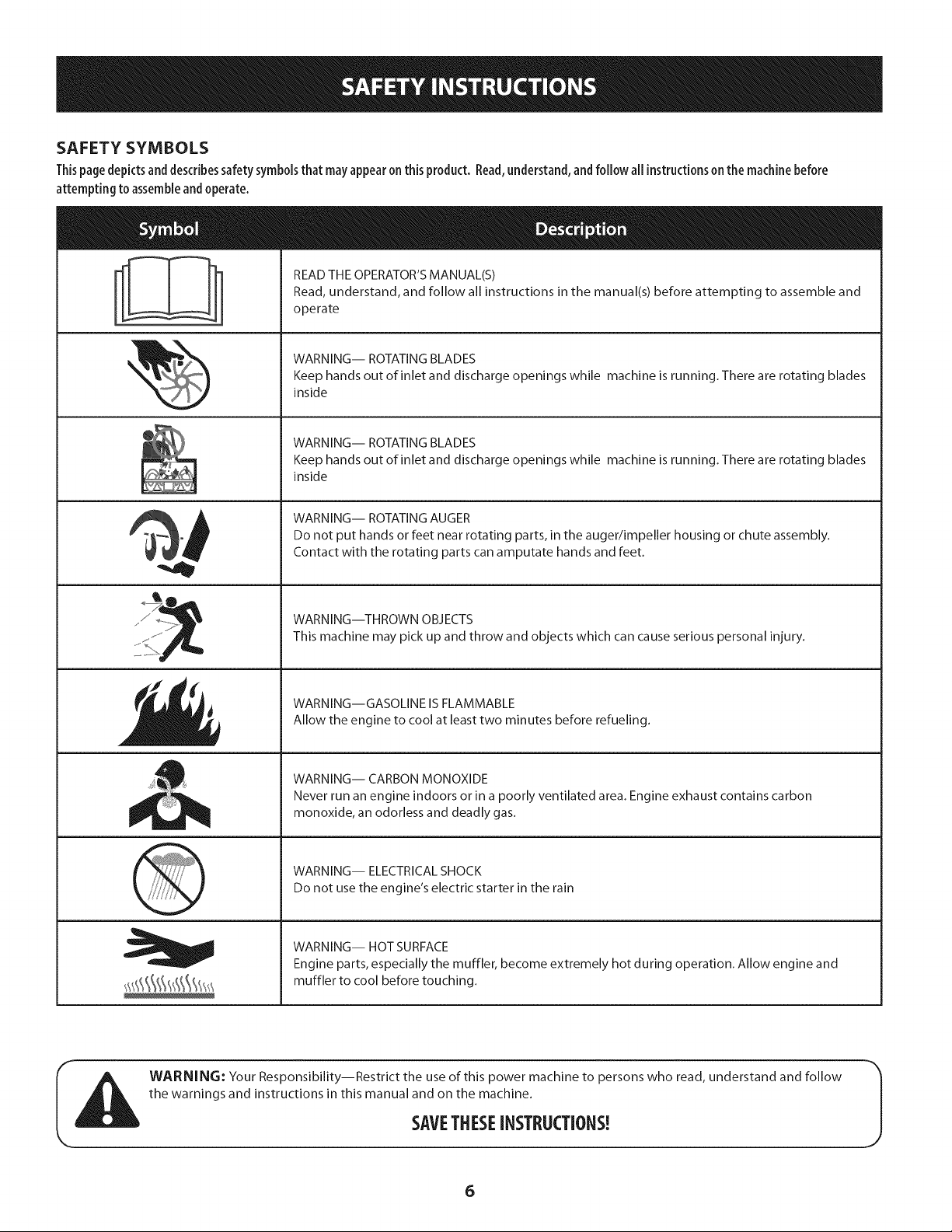
SAFETY SYMBOLS
Thispage depicts and describes safety symbols that may appear on this product. Read,understand, and follow all instructions on the machine before
attempting to assemble and operate.
READ THE OPERATOR'S MANUAL(S)
Read, understand, and follow all instructions in the manual(s) before attempting to assemble and
operate
WARNING-- ROTATING BLADES
Keep hands out of inlet and discharge openings while machine is running. There are rotating blades
inside
WARNING-- ROTATING BLADES
Keep hands out of inlet and discharge openings while machine is running. There are rotating blades
inside
WARNING-- ROTATING AUGER
Do not put hands or feet near rotating parts, in the auger/impeller housing or chute assembly.
Contact with the rotating parts can amputate hands and feet.
WARNING--THROWN OBJECTS
This machine may pick up and throw and objects which can cause serious personal injury.
WARNING--GASOLINE ISFLAMMABLE
Allow the engine to cool at least two minutes before refueling.
WARNING-- CARBON MONOXIDE
Never run an engine indoors or in a poorly ventilated area. Engine exhaust contains carbon
monoxide, an odorless and deadly gas.
WARNING-- ELECTRICAL SHOCK
Do not use the engine's electric starter in the rain
WARNING-- HOT SURFACE
Engine parts, especially the muffler, become extremely hot during operation. Allow engine and
muffler to cool before touching.
WARNING: Your Responsibility--Restrict the use of this power machine to persons who read, understand and follow
the warnings and instructions in this manual and on the machine.
SAVETHESEiNSTRUCTIONS!
6
Page 7

This pageleft intentionallyblank.
7
Page 8
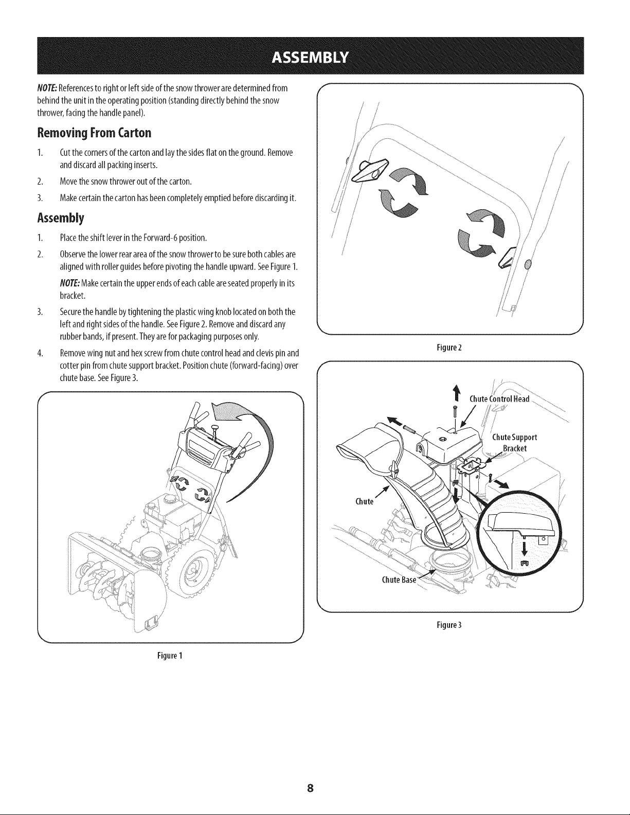
NOTE:Referencestorightor leftsideofthesnowthroweraredeterminedfrom
behindtheunitin theoperatingposition(standingdirectlybehindthesnow
thrower,facingthehandlepanel).
Removing FromCarton
1. Cutthecornersof thecartonandlaythesidesflat ontheground.Remove
anddiscardallpackinginserts.
2. Movethesnowthroweroutofthecarton.
3. Makecertainthecartonhasbeencompletelyemptiedbeforediscardingit.
Assembly
1.
PlacetheshiftleverintheForward-6position.
2.
Observethelowerrearareaofthesnowthrowerto besurebothcablesare
alignedwith rollerguidesbeforepivotingthehandleupward.SeeFigure1.
NOTE:Makecertaintheupperendsofeachcableareseatedproperlyinits
bracket.
3. Securethehandlebytighteningtheplasticwingknoblocatedonboththe
leftandrightsidesof thehandle.SeeFigure2.Removeanddiscardany
rubberbands,ifpresent.Theyareforpackagingpurposesonly.
4. Removewing nutandhexscrewfromchutecontrolheadandclevispinand
cotterpinfromchutesupportbracket.Positionchute(forward-facing)over
chutebase.SeeFigure3.
k,.
f
Figure2
/
/
/
/ /
/
/
Figure1
ChuteControlHead ................
/
ChuteSupport
Bracket
j
Figure3
J
8
Page 9
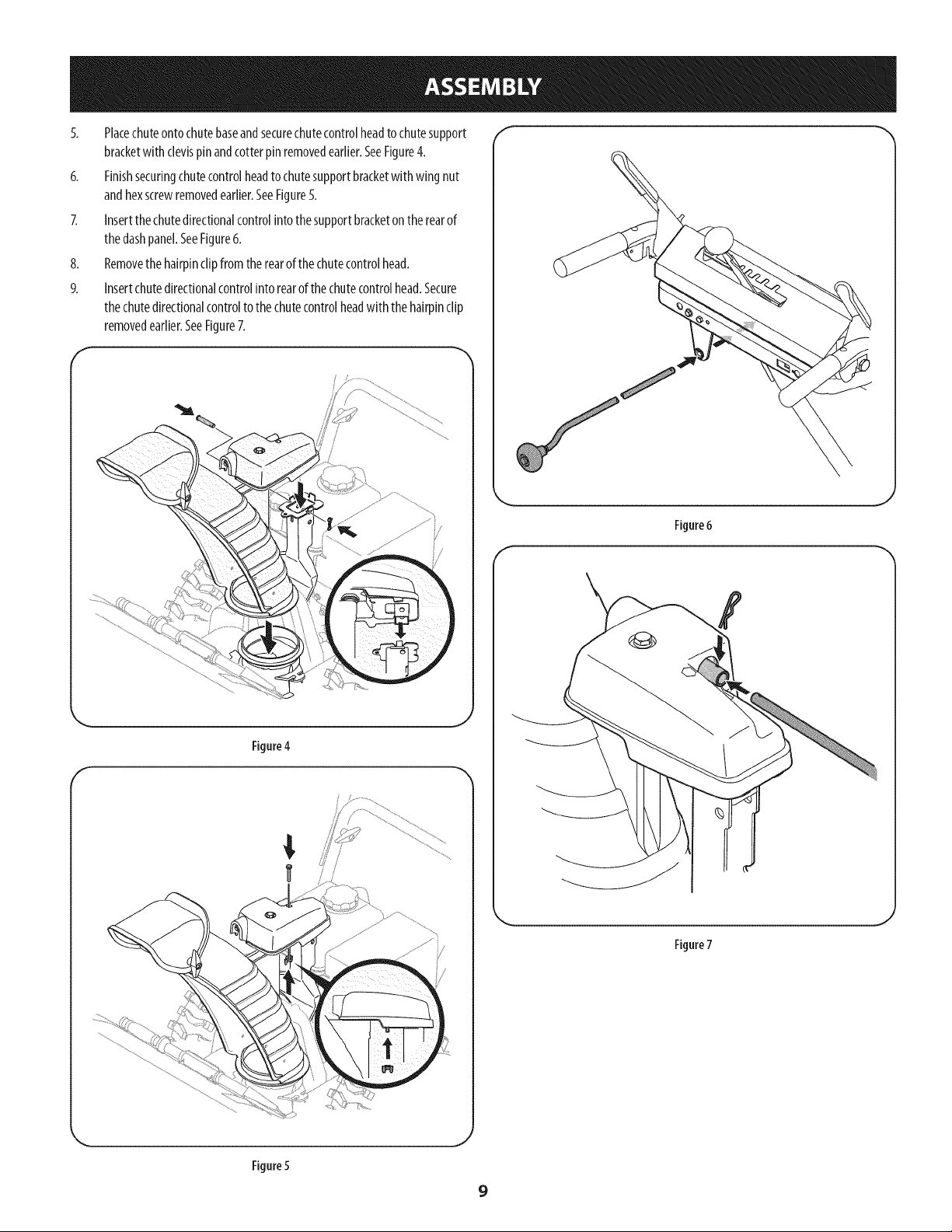
5. Placechuteontochutebaseandsecurechutecontrolheadtochutesupport
bracketwithclevispinandcotterpinremovedearlier.SeeFigure4.
6. Finishsecuringchutecontrolheadtochutesupportbracketwithwingnut
andhexscrewremovedearlier.SeeFigure5.
7. Insertthechutedirectionalcontrolintothesupportbracketontherearof
thedashpanel.SeeFigure6.
8. Removethehairpinclipfromtherearofthechutecontrolhead.
9. Insertchutedirectionalcontrolintorearofthechutecontrolhead.Secure
thechutedirectionalcontroltothechutecontrolheadwith thehairpinclip
removedearlier.SeeFigure7.
f
Figure6
f
\
Figure4
f
Figure7
Figure5
9
Page 10
Set-Up f
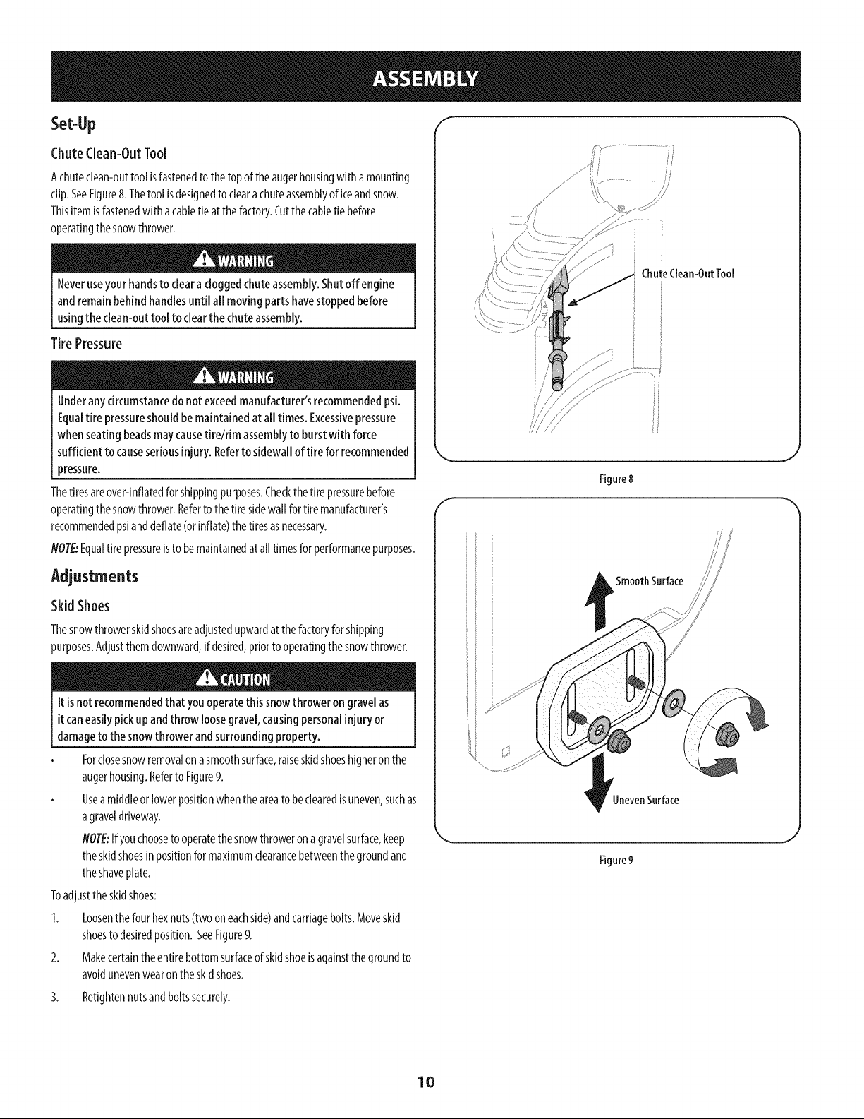
ChuteClean-OutTool
Achuteclean-outtoolisfastenedtothetopoftheaugerhousingwithamounting
clip.SeeFigure8.Thetoolisdesignedtoclearachuteassemblyoficeandsnow.
Thisitemisfastenedwitha cabletieatthefactory.Cutthecabletiebefore
operatingthesnowthrower.
Neveruseyour handstoclearacloggedchuteassembly,Shutoff engine
andremainbehindhandlesuntil all movingpartshavestoppedbefore
usingthe clean-outtool to clearthe chuteassembly.
TirePressure
Underanycircumstancedo notexceedmanufacturer'srecommendedpsi.
Equaltire pressureshouldbe maintainedat alltimes. Excessivepressure
when seatingbeadsmaycausetirelrim assemblyto burstwith force
sufficient tocauseseriousinjury. Refertosidewalloftirefor recommended
pressure.
Thetiresareover-inflatedforshippingpurposes.Checkthetire pressurebefore
operatingthesnowthrower.Refertothetiresidewallfor tiremanufacturer's
recommendedpsianddeflate(orinflate)thetiresasnecessary.
NOTE:Equaltirepressureisto bemaintainedatalltimesforperformancepurposes.
Adjustments
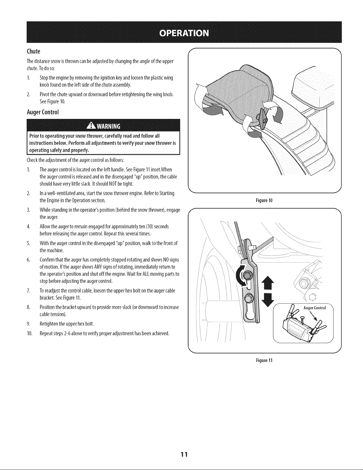
SkidShoes
Thesnowthrowerskidshoesareadjustedupwardatthefactoryforshipping
purposes.Adjustthemdownward,ifdesired,priortooperatingthesnowthrower.
ChuteClean-OutTool
/
/ ii
Figure8
f
SmoothSurface
Itis notrecommendedthat youoperatethis snowthroweron gravelas
itcaneasilypickupandthrow loosegravel,causingpersonalinjuryor
damageto thesnowthrower andsurroundingproperty.
Forclosesnowremovalonasmoothsurface,raiseskidshoeshigheronthe
augerhousing.Referto Figure9.
Useamiddleorlowerpositionwhentheareatobeclearedisuneven,suchas
agraveldriveway.
NOTE:Ifyouchoosetooperatethesnowthroweron agravelsurface,keep
theskidshoesinpositionformaximumclearancebetweenthegroundand
theshaveplate.
Toadjusttheskidshoes:
1. Loosenthefourhexnuts(twooneachside)andcarriagebolts.Moveskid
shoestodesiredposition.SeeFigure9.
2. Makecertaintheentirebottomsurfaceofskidshoeisagainstthegroundto
avoidunevenwearontheskidshoes.
3. Retightennutsandboltssecurely.
UnevenSurface
Figure9
10
Page 11
Thedistancesnowisthrowncanbeadjustedbychangingtheangleoftheupper
chute.Todoso:
Stoptheenginebyremovingtheignitionkeyandloosentheplasticwing
knobfoundontheleft sideofthechuteassembly.
2.
Pivotthechuteupwardordownwardbeforeretighteningthewingknob.
SeeFigure10.
AugerControl
Priorto operatingyoursnowthrower,carefullyreadandfollow all
instructionsbelow.Performall adjustmentsto verifyyoursnowthrower is
operatingsafelyandproperly.
Checktheadjustmentoftheaugercontrolasfollows:
1. Theaugercontrolislocatedonthelefthandle.SeeFigure11inset.When
theaugercontrolisreleasedandinthedisengaged"up"position,thecable
shouldhaveverylittle slack.ItshouldNOTbetight.
2. Inawell-ventilatedarea,startthesnowthrowerengine.Referto Starting
theEngineintheOperationsection.
3. Whilestandingintheoperator'sposition(behindthesnowthrower),engage
theauger.
4. Allowtheaugerto remainengagedfor approximatelyten(10)seconds
beforereleasingtheaugercontrol.Repeatthisseveraltimes.
5. Withtheaugercontrolin thedisengaged"up"position,walkto thefrontof
themachine.
6. ConfirmthattheaugerhascompletelystoppedrotatingandshowsNOsigns
ofmotion.IftheaugershowsANYsignsofrotating,immediatelyreturnto
theoperator'spositionandshutofftheengine.WaitforALLmovingpartsto
stopbeforeadjustingtheaugercontrol.
7. Toreadjustthecontrolcable,loosenthe upperhexbolt ontheaugercable
bracket.SeeFigure11.
8. Positionthebracketupwardtoprovidemoreslack(ordownwardtoincrease
cabletension).
9. Retightentheupperhexbolt.
10. Repeatsteps2-6aboveto verifyproperadjustmenthasbeenachieved.
.J
Figure10
f
\\
..........
J
Figure11
11
Page 12
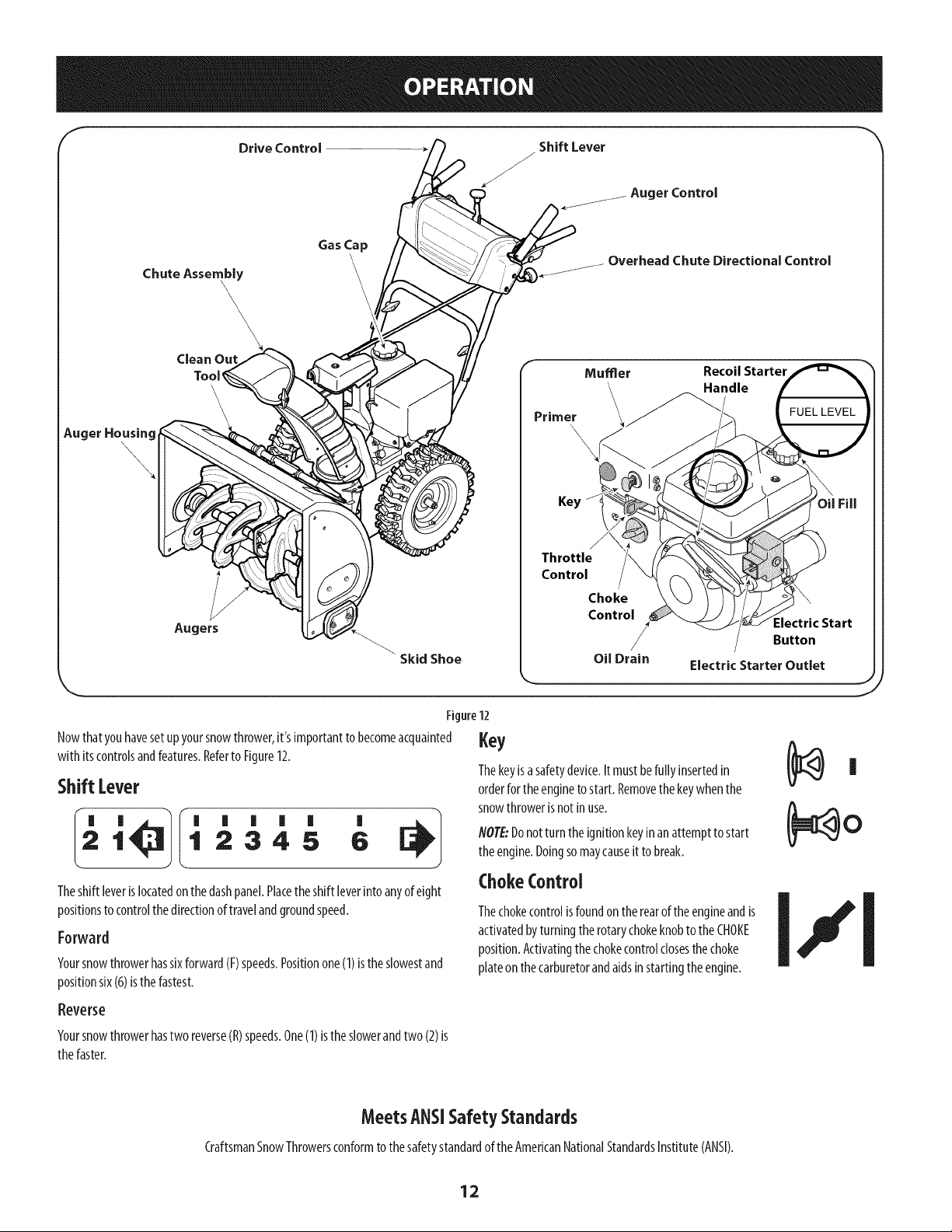
Chute Assembly
\\\
Drive Control
Gas Cap
\
Shift Lever
J
Auger Control
Chute Directional Control
cI
_ugerHousing_\\_,
,L!,
Augers
"Skid Shoe
Figure12
Nowthatyouhavesetupyoursnowthrower,it'simportanttobecomeacquainted
with itscontrolsandfeatures.Referto Figure12.
ShiftLever
Recoil Starter
Handle
Throttle
Control
Choke
Control
Oil Drain Electric Starter Outlet
Key
Thekeyisasafetydevice.It mustbefullyinsertedin
orderfor theenginetostart.Removethekeywhenthe
snowthrowerisnotinuse.
:lectric Start
Button
J
|
1 2345 6
I_ '_1 ' ' ' ' ' '
Theshiftleverislocatedonthedashpanel.Placetheshiftleverintoanyofeight
positionsto controlthedirectionoftravelandgroundspeed.
Forward
Yoursnowthrowerhassixforward(F)speeds.Positionone(1)isthe slowestand
positionsix(6)isthe fastest.
Reverse
Yoursnowthrowerhastworeverse(R)speeds.One(1)lstheslowerandtwo(2)ls
thefaster.
MeetsANSiSafetySta.dards
CraftsmanSnowThrowersconformtothesafetystandardoftheAmericanNationalStandardsInstitute(ANSI).
NOTE:Donotturn theignitionkeyinanattempttostart
theengine.Doingsomaycauseit tobreak.
ChokeControl
Thechokecontrolisfoundontherearoftheengineandis
activatedbyturningtherotarychokeknobtotheCHOKE
position.Activatingthechokecontrolclosesthechoke
plateonthecarburetorandaidsinstartingtheengine.
12
Page 13
Throttlecontrol
Thethrottlecontrolislocatedontherearoftheengine.Itregulatesthespeedofthe
engineandwillshutoffthe enginewhenmovedintotheSTOPposition.
Depressingtheprimerforcesfueldirectlyintothe _e 444
engine'scarburetortoaidincold-weatherstarting. 3X
RecoilStarter Handle
DriveControl/Auger Control Lock
f DRIVE
CONTROL
Thishandleisusedtomanuallystarttheengine.
ElectricStarter Button
Pressingtheelectricstarterbuttonengagestheengine'selectricstarterwhen
pluggedintoa 120Vpowersource.
ElectricStarter Outlet
Requirestheuseofathree-prongoutdoorextensioncordanda120Vpowersource/
walloutlet.
OUFill
Engineoillevelcanbecheckedandoiladdedthroughtheoil fill.
GasCap
Unthreadthegascaptoaddgasolinetothefueltank.
Auger
Whenengaged,theaugerbladesrotateanddrawsnowintotheaugerhousing.
ChuteAssembly
Snowdrawnintotheaugerhousingisdischargedoutthechuteassembly.
AugerControl
f
AUGER
CONTROL
Thedrivecontrolislocatedontheright handle.Squeezethecontrolgripagainstthe
handletoengagethewheeldrive.Releasetostop.
Thedrivecontrolalsolockstheaugercontrolsoyoucanoperatethechute
directionalcontrolwithoutinterruptingthesnowthrowingprocess.Iftheauger
controlisengagedsimultaneouslywiththedrivecontrol,theoperatorcanrelease
theaugercontrol(ontheleft handle)andtheaugerswill remainengaged.Release
bothcontrolstostoptheaugersandwheeldrive.
NOTE:Alwaysreleasethedrivecontrolbeforechangingspeeds.Failuretodosowill
resultinincreasedwearonyourmachine'sdrivesystem.
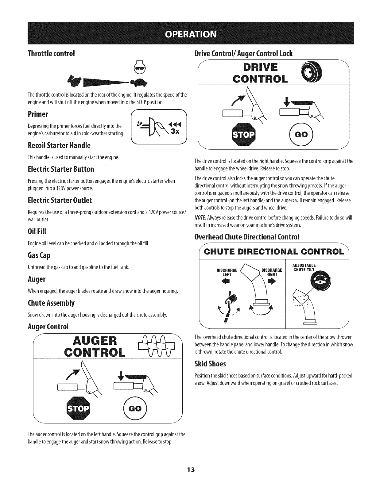
OverheadChuteDirectional Control
/CHUTE DIRECTIONAL CONTROL
ADJUSTABLE
DISCHARGE
LEFT
Theoverheadchutedirectionalcontrolislocatedin thecenterofthesnowthrower
betweenthehandlepanelandlowerhandle.Tochangethedirectioninwhichsnow
isthrown,rotatethechutedirectionalcontrol.
SkidShoes
CHUTETILT
J
Theaugercontrolislocatedonthelefthandle.Squeezethecontrolgripagainstthe
handletoengagetheaugerandstartsnowthrowingaction.Releasetostop.
Positiontheskidshoesbasedonsurfaceconditions.Adjustupwardforhard-packed
snow.Adjustdownwardwhenoperatingongravelorcrushedrocksurfaces.
13
Page 14
Clean-OutTool
Neveruseyour handstoclearacloggedchuteassembly.Shutoff engine
andremainbehindhandlesuntil all movingpartshavestoppedbefore
usingthe clean-outtool to clearthechuteassembly.
Thechutedean-outtoolisconvenientlyfastenedtotherearoftheaugerhousing
with amountingclip.Shouldsnowandicebecomelodgedinthechuteassembly
duringoperation,proceedasfollowstosafelycleanthechuteassemblyandchute
opening:
1. ReleaseboththeAugerControlandtheDriveControl.
2. Stoptheenginebyremovingthe ignitionkey.
3. Removetheclean-outtoolfromtheclipwhichsecuresit to therearofthe
augerhousing.
4. Usetheshovel-shapedendoftheclean-outtoolto dislodgeandscoopany
snowandicewhichhasformedinandnearthechuteassembly.
5. Refastentheclean-outtoolto themountingdipontherearof theauger
housing,reinserttheignitionkeyandstartthesnowthrower'sengine.
6. Whilestandingintheoperator'sposition(behindthesnowthrower),engage
theaugercontrolforafewsecondstoclearanyremainingsnowandicefrom
thechuteassembly.
BeforeStartingEngine
Read,understand,andfollow all instructionsandwarningsonthe
machineandinthis manualbeforeoperating.
Oil
Theunitwasshippedwithoilintheengine.Checkoillevelbeforeeachoperationto
ensureadequateoilintheengine.
flO?E:Besuretochecktheengineonalevelsurfacewith theenginestopped.
1. Removetheoilfiller cap/dipstickandwipethedipstickclean.
2. Insertthecap/dipstickintotheoilfiller neck,butdoNOTscrewitin.
3. Removetheoilfiller cap/dipstick.Ifthelevelislow,slowlyaddoil(5W-30,
with aminimumclassificationofSF/SG)until oillevelregistersbetweenhigh
(H)andlow(L).
flOTE:Donotoverfill.Overfillingwithoilmayresultinenginesmoking,hard
startingorsparkplugfouling.
4.
Replaceandtightencap/dipstickfirmlybeforestartingengine.
Gasoline
Useautomotivegasoline(unleadedorlowleadedto minimizecombustionchamber
deposits)witha minimumof87 octane.Gasolinewith upto10%ethanolor15%
MTBE(MethylTertiaryButylEther)canbeused.Neveruseanoil/gasolinemixture
ordirtygasoline.Avoidgettingdirt, dust,orwaterinthefueltank.DONOTuseE85
gasoline.
Refuelinawell-ventilatedareawith theenginestopped.Donotsmokeor
allowflamesorsparksin theareawheretheengineisrefueledorwhere
gasolineisstored.
Donotoverfillthefueltank.Afterrefueling,makesurethetankcapisclosed
properlyandsecurely.
Becarefulnottospillfuelwhenrefueling.Spilledfuelorfuelvapormay
ignite.Ifanyfuelisspilled,makesuretheareaisdry beforestartingthe
engine.
Avoidrepeatedorprolongedcontactwithskinorbreathingofvapor.
Useextremecarewhenhandling gasoline.Gasolineisextremely
flammableandthevaporsareexplosive.Neverfuel the machineindoorsor
while theengineishotorrunning. Extinguishcigarettes,cigars,pipesand
othersourcesof ignition.
1.
Cleanaroundfuelfill beforeremovingcapto fuel.
2.
Afuel levelindicatoris locatedinthefueltank.SeeFigure12inset.Be
carefulnottooverfill.Filltankuntil fuelreachesthefuellevelindicatorto
allowspacefor fuelexpansion.
Starting TheEngine
Alwayskeephandsandfeet clearof movingparts.Donotuseapressurized
starting fluid. Vaporsareflammable.
flOTE:Allowtheengineto warmupfor afewminutesafterstarting.Theenginewill
notdevelopfull poweruntilit reachesoperatingtemperatures.
1. Makecertainboththeaugercontrolanddrivecontrolarein thedisengaged
(released)position.
2. Insertkeyintoslot.Makesureit snapsintoplace.Donotattempttoturn the
key.
NOTE:Theenginecannotstartwithoutthekeyfullyinsertedintothe
ignitionswitch.
ElectricStarter
Theelectric starterisequippedwith a groundedplug,andisdesignedto
operateon 120voltAChouseholdcurrent.It mustbeusedwith a properly
groundedthree-prong receptacleat alltimesto avoidthe possibility
ofelectricshock.Followall instructionscarefully priorto operatingthe
electricstarter. DONOTuseelectricstarter in therain.
Determinethatyourhome'swring isathree-wiregroundedsystem.Aska licensed
electricianifyouarenotcertain.
Ifyouhavea groundedthree-prongreceptacle,proceedasfollows.If youdonot
havetheproperhousewiring,DONOTusetheelectricstarterunderanyconditions.
1. Pluganextensioncordintotheoutletlocatedontheengine'ssurface.Plug
theotherendofextensioncordintoathree-prong120-volt,grounded,AC
outletinawell-ventilatedarea.
Theextensioncordcanbeanylength, but must beratedfor 15ampsat
125volts,groundedand ratedforoutdoor use.
14
Page 15
2. Movethrottlecontrolto FAST(rabbit)_Jl__ position.
3 MovechoketotheCHOKEI,'Ipos t on co,deng nestart),fengine s
warm,placechokein RUNposition.
4. Pushprimerthree(3)times,makingsuretocoverventholeinprimerbulb
whenpushing.Ifengineiswarm,pushprimeronlyonce.Alwayscovervent
holewhenpushing.Coolweathermayrequireprimingto berepeated.
5. Pushstarterbuttonto startengine.Oncetheenginestarts,immediately
releasestarterbutton.Electricstarterisequippedwith thermaloverload
protection;systemwilltemporarilyshut-downtoallowstartertocoolif
electricstarterbecomesoverloaded.
6.
Astheenginewarms,slowlyrotatethechokecontroltoRUNposition.Ifthe
enginefalters,restartengineandrunwith chokeathalf-chokepositionfora
shortperiodoftime,andthenslowlyrotatethechokeinto RUNposition.
Afterengineisrunning,disconnectpowercordfromelectricstarter.When
disconnecting,alwaysunplugtheendatthewalloutletbeforeunplugging
theoppositeendfromtheengine.
RecoilStarter
ToEngageDrive
1. WiththethrottlecontrolintheFast(rabbit)_ _1 position,moveshiftlever
intooneofthesixforward(F)positionsortwo reverse(R)positions.Selecta
speedappropriatefor thesnowconditionsandapaceyou'recomfortable
with.
flOTE:WhenselectingaDriveSpeed,usetheslowerspeedsuntilyouare
comfortableandfamiliarwiththeoperationofthesnowthrower.
2. Squeezethedrivecontrolagainstthehandleandthesnowthrowerwill
move.Releaseit anddrivemotionwill stop.
NOTE:NEVERrepositiontheshiftlever(changespeedsordirectionoftravel)
withoutfirstreleasingthedrivecontrolandbringingthesnowthrowertoa
completestop.Doingsowillresultinprematureweartothesnowthrower'sdrive
system.
ToEngageAuger
Toengagetheaugerandstartthrowingsnow,squeezetheaugercontrol
againstthelefthandle.Releaseto stoptheauger.
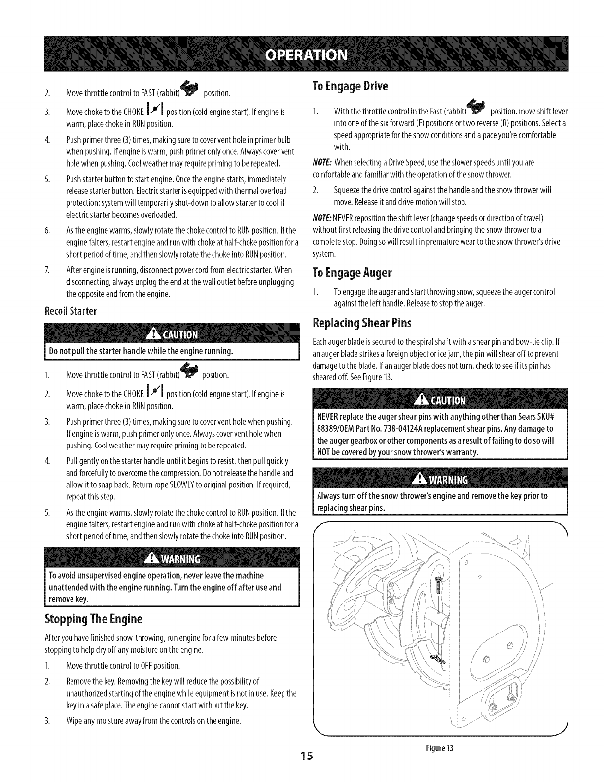
ReplacingShearPins
Eachaugerbladeissecuredtothespiralshaftwithashearpinandbow-tieclip.If
Donotpullthe starter handlewhilethe enginerunning.
1. Movethrottlecontrolto FAST(rabbit)_ _j position.
2. MovechoketotheCHOKEI,.1position(coldenginestart).Ifengineis
warm,placechokein RUNposition.
3. Pushprimerthree(3)times,makingsuretocoverventholewhenpushing.
Ifengineiswarm,pushprimeronlyonce.Alwayscoverventholewhen
pushing.Coolweathermayrequireprimingtoberepeated.
4. Pullgentlyonthestarterhandleuntilit beginsto resist,thenpullquickly
andforcefullytoovercomethecompression.Donotreleasethe handleand
allowit tosnapback.ReturnropeSLOWLYtooriginalposition.Ifrequired,
repeatthisstep.
5. Astheenginewarms,slowlyrotatethechokecontrolto RUNposition.Ifthe
enginefalters,restartengineandrunwith chokeathalf-chokepositionfora
shortperiodoftime,andthenslowlyrotatethechokeinto RUNposition.
anaugerbladestrikesaforeignobjectoricejam,thepinwill shearoff toprevent
damagetotheblade.Ifanaugerbladedoesnotturn,checktoseeif itspinhas
shearedoff. SeeFigure13.
NEVERreplacetheaugershearpinswith anything otherthan SearsSKU#
88389/0EMPartNo.738-04124Areplacementshearpins.Anydamageto
the augergearboxorother componentsasaresult offailing to dosowill
NOTbecoveredbyyoursnowthrower'swarranty.
Alwaysturn off thesnowthrower'sengineandremovethekeypriorto
replacingshearpins.
E
Toavoidunsupervisedengineoperation,neverleavethe machine
unattendedwith theenginerunning. Turntheengineoff after useand
removekey.
Stopping TheEngine
Afteryouhavefinishedsnow-throwing,runengineforafewminutesbefore
stoppingto helpdryoffanymoistureon theengine.
1. Movethrottlecontrolto OFFposition.
2. Removethekey.Removingthe keywillreducethepossibilityof
unauthorizedstartingoftheenginewhileequipmentisnotinuse.Keepthe
keyina safeplace.Theenginecannotstartwithout thekey.
3. Wipeanymoistureawayfromthecontrolsontheengine.
15
J
Figure13
Page 16

MAINTENANCESCHEDULE
Beforeperforminganytypeof maintenance/service,disengageallcontrols
andstopthe engine.Wait until allmoving partshavecometo a complete
stop.Disconnectsparkplug wireand grounditagainstthe engineto
preventunintendedstarting.
Followthemaintenanceschedulegivenbelow.Thischartdescribesservice
guidelinesonly.UsetheServiceLogcolumntokeeptrackofcompleted
maintenancetasks.TolocatethenearestSearsServiceCenterorto scheduleservice,
simplycontactSearsat1-800-4-MY-HOME®.
EachUseandevery5hours
Ist5hours
Annuallyor25hours
Annuallyor50hours
Annuallyor100hours
BeforeStorage
1. Engineoil level
2. Looseormissinghardware
3. Unitandengine.
1. Englneoil
1. Sparkplug
2. Controllinkagesandpivots
3. Wheels
4. GearshaftandAugershaft
1. Englneoil
1. Sparkplug
1. Fuelsystem
GENERALRECOMMENDATIONS
CheckingEngineOil
Beforelubricating, repairing,or inspecting,disengageall controlsandstop
engine.Waituntil all movingparts havecometo acompletestop.
NOTE:Checktheoillevelbeforeeachuseto besurecorrectoillevelismaintained.
Whenaddingoiltotheengine,refertoviscositychartbelow.Engineoilcapacity
is600ml(approx.20oz.).Donotover-fill.Usea4-stroke,oranequivalenthigh
detergent,premiumqualitymotoroilcertifiedtomeetorexceedU.S.automobile
manufacturer'srequirementsforserviceclassificationSG,SF.Motoroilsclassified
SG,SFwillshowthisdesignationonthecontainer.
1. Removetheoilfiller cap/dipstkkandwipethedipstickclean.
2. Insertthecap/dipstickintotheoilfillerneck,butdoNOTscrewitin.
3. Removetheoilfiller cap/dipstick.Iflevelislow,slowlyaddoiluntiloillevel
registersbetweenhigh(H)andlow(L).SeeFigure14.
4. Replaceandtightencap/dipstickfirmlybeforestartingengine.
ChangingEngineOil
NO/E:Changetheengineoilafterthefirst5 hoursofoperationandoncea season
orevery50hoursthereafter.
1. Drainfuelfromtankbyrunningengineuntil thefueltankisempty.Besure
fuelfill capissecure.
2. Placesuitableoilcollectioncontainerunderoil drainplug.
3. Removeoildrainplug.SeeFigure15onnextpage.
4. Tipunittodrainoil intothecontainer.Usedoilmustbedisposedofat a
propercollectioncenter.
1. Check
2. Tightenorreplace
3. Clean
1. Change
1. Check
2. Lubewithlight oil
3. Lubewithmultipurposeautogrease
4. Lubewithlight oil
1. Change
1. Change
1. Runengineuntilitstopsfromlackoffuel
J
Figure14
Usedoil isa hazardouswasteproduct.Disposeofusedoil properly.Donot
discardwith householdwaste.Checkwithyourlocalauthorities or Sears
ServiceCenterforsafedisposal/recyclingfacilities.
Reinstallthedrainplugandtightenitsecurely.
16
Page 17

Refillwith therecommendedoilandchecktheoil level.SeeRecommended
OilUsagechart.Theengine'soilcapacityis20ounces.
(%-40 °-20 o 0o 20o 40o
(oc) -30° -20° -10° 0°
DONOTusenondetergentoil or 2-strokeengineoil. it couldshortenthe
engine'sservicelife.
7. Reinstalltheoilfillercap/dipsticksecurely.
Thoroughlywashyour handswith soapandwater assoonaspossibleafter
handlingusedoil.
CheckingSparkPlug
OilDrain
Plug \
Figure15
E
SparkPlug
DONOTcheckforsparkwith sparkplug removed.DONOTcrankenginewith
sparkplug removed.
Ifthe enginehasbeenrunning,themuffler will beveryhot. Becarefulnot
to touchthe muffler.
NOTE:Checkthe sparkplugonceaseasonor every25hoursofoperation.Change
thesparkplugonceaseasonorevery100hours.Toensureproperengineoperation,
thesparkplugmustbeproperlygappedandfreeof deposits.
1. Removethesparkplugbootanduseasparkplugwrenchtoremovethe
plug.SeeFigure16.
2. Visuallyinspectthesparkplug.Discardthesparkplugifthereisapparent
wear,orif theinsulatoriscrackedorchipped.Cleanthesparkplugwitha
wirebrushifit isto bereused.
3.
Measurethepluggapwith afeelergauge.Correctasnecessarybybending
sideelectrode.SeeFigure17.Thegapshouldbesetto.02-.03inches(0.60-
0.80mm).
4. Checkthatthesparkplugwasherisin goodconditionandthreadthespark
pluginbyhandtopreventcross-threading.
5. Afterthesparkplugisseated,tightenwithasparkplugwrenchtocompress
thewasher.
NOTE:Wheninstallinganewsparkplug,tighten1/2-turnafterthesparkplug
seatstocompressthewasher.Whenreinstallingausedsparkplug,tighten1/8-to
1/4-turnafterthesparkplugseatsto compressthewasher.
SparkPlugBoot
Figure16
Electrode
Thesparkplug mustbetightened securely.Aloosesparkplugcanbecome
very hotandcandamagetheengine.
Figure17
17
Page 18

Lubrication "I
GearShaft
Thegear(hex)shaftshouldbelubricatedatleastonceaseasonorafterevery25
hoursofoperation.
I. Topreventspillage,removeallfuelfromtankbyrunningengineuntilit
stops.
2. Carefullypivotthesnowthrowerupandforwardsothatit restsontheauger
housing.
3. Removethelowerframecoverfromtheundersideof thesnowthrowerby
removingtheself-tappingscrewswhichsecureit.
4. Applya lightcoatingofengineoil(or3-in-1oil)tothehexshaft.SeeFigure
18.
NOTE:Whenlubricatingthehexshaft,becarefulnottogetanyoilonthealuminum
driveplateorrubberfrictionwheel.Doingsowill hinderthesnowthrower'sdrive
system.Wipeoffanyexcessorspilledoil.
Wheels
Atleastonceaseason,removebothwheels.Cleanandcoattheaxleswitha
multipurposeautomotivegreasebeforereinstallingwheels.
AugerShaft
Atleastonceaseason,removetheshearpinsonaugershaft.Spraylubricantinside
shaft,andaroundthespacersandflangebearingsfoundat eitherendoftheshaft.
SeeFigure19.
ShavePlateand SkidShoes
Theshaveplateandskidshoesonthebottomofthesnowthroweraresubjectto
wear.Theyshouldbecheckedperiodkallyandreplacedwhennecessary.
flOT£:Theskidshoesonthismachinehavetwowearedges.Whenonesidewears
out,theycanberotated180°tousetheotheredge.
Toremoveskidshoes:
Removethetwocarriagebolts,washers,andhexflangenutsthatsecure
eachskidshoetothesnowthrower.
2. Reassemblenewskidshoeswiththefourcarriagebolts(twooneachside),
washers,andhexflangenuts.Referto Figure20.
Toremoveshaveplate:
1. Removethecarriageboltsandhexnutswhichattachittothesnowthrower
housing.
2. Reassemblenewshaveplate,makingsureheadsof carriageboltsaretothe
insideof housing.Tightensecurely.SeeFigure20.
f
J
Figure18
f
f_S /
Figure19
NOTE:Angers not shown for clarity.
Figure20
4_
18
Page 19

Adjustments f
Shift Cable
Ifthefull rangeofspeeds(forwardandreverse)cannotbeachieved,refertothe
figuretotherightandadjusttheshiftcableasfollows:
I,
Placetheshiftleverinthefastestforwardspeedposition(F6).
2.
Loosenthehex nutontheshiftcableindexbracket.SeeFigure21.
3.
Pivotthebracketdownwardtotakeupslackinthecable.
4.
Retightenthehexnut.
Drive
Control
Whenthedrivecontrolisreleasedandinthedisengaged"up" position,thecable
shouldhaveverylittle slack.ItshouldNOTbetight. Also,ifthereisexcessiveslack
inthedrivecableor iftheunitexperiencesintermittentdrivewhileusing,thecable
mayneedtobeadjusted.Checktheadjustmentofthedrivecontrolasfollows:
1. Withthedrivecontrolreleased,pushthesnowthrowergentlyforward.The
unitshouldrollfreely.
2. Engagethedrivecontrolandgentlyattemptto pushthesnowthrower
forward.Thewheelsshouldnotturn.Theunitshouldnotrollfreely.
3. Withthedrivecontrolreleased,movetheshift leverbackandforthbetween
theR2positionandtheF6positionseveraltimes.Thereshouldbeno
resistanceintheshiftlever.
4,
Ifanyoftheabovetestsfailed,thedrivecableisinneedofadjustment.
Proceedasfollows:
a. Shutoff theengineasinstructedinthe Operationsection.
b. Loosenthelowerhexboltonthedrivecablebracket.SeeFigure22.
c. Positionthebracketupwardto providemoreslack(ordownwardto
increasecabletension).
d. RetJghtenthelowerhexbolt.
Chute
/
Figure21
E
Ifthechutefallsto remainstationaryduringoperation,thepre-loadofthechute
canbeadjustedbytighteningthehexnutfoundonthefront ofthechutecontrol
head.
Toincreasethepreload,tightenthehexnutclockwisein lgturnintervals.
SeeFigure23.
2.
Ifthechutedirectionalcontrolisdifficultto crank,decreasethepreloadby
looseningthehexnutcounterclockwisein lg turnintervals.
Figure22
//
J
Figure23
19
Page 20

AugerControl
RefertotheAssemblysectionforinstructionsonadjustingtheaugercontrolcable.
SkidShoes
RefertotheAssemblysectionforinstructionsonadjustingtheskidshoes.
8eR Replacement
Auger Belt
Toremoveandreplaceyoursnowthrower'saugerbelt,proceedasfollows:
I. Topreventspillage,removeallfuelfromtankbyrunningengineuntilit
stops.
2. Removetheplasticbeltcoveronthefrontoftheenginebyremovingthetwo
self-tappingscrews.SeeFigure24.
3. Rolltheaugerbeltoffthe enginepulley.SeeFigure25.
4. Carefullypivotthesnowthrowerupandforwardsothatit restsontheauger
housing.
5. Removetheframecoverfromtheundersideof thesnowthrowerby
removingfourself-tappingscrewswhichsecureit. SeeFigure26.
f
J
Figure24
Figure26
,J
Figure25
.J
2O
Page 21

Loosenandremovetheshoulderscrewwhichactsasabeltkeeper.Referto
Figure27.
Removethebeltfromaroundtheaugerpulley,andslipthebeltbetweenthe
supportbracketandtheaugerpulley.SeeFigure28.
NOTE:Engagingtheaugercontrolwill easeremovalandreinstallationofthe
belt.
8.
Reassembleaugerbeltbyfollowinginstructionsinreverseorder.
NOTE:DoNOTforgettoreinstalltheshoulderscrewandreconnectthespring
totheframeafterinstallingareplacementaugerbelt.
PerformtheAugerControltestoutlinedintheAssemblysectionofthis
manual.
Drive Belt
NOTE:Severalcomponentsmustberemovedandspecialtoolsarerequiredinorder
toreplacethesnowthrower'sdrivebelt.ContactthenearestSearsParts& Repair
Centerto havethedrivebeltreplaced.
FrictionWheelRemoval
Ifthesnowthrowerfailstodrivewiththedrivecontrolengaged,andperforming
thedrivecontrolcableadjustmentfailstocorrecttheproblem,thefrictionwheel
mayneedtobereplaced.Followtheinstructionsbelow.Examinethefrictionwheel
rubberfor signsofwearorcrackingandreplacewheelifnecessary.
1. Topreventspillage,removeallfuelfromtankbyrunningengineuntil it
stops.
2. Placetheshiftleverinfirst Forward(F1)position.
3. Carefullypivotthesnowthrowerupandforwardsothatitrestson theauger
housing.
4. Removetheframecoverfromtheundersideof thesnowthrowerby
removingtheself-tappingscrewswhichsecureit.
5. Removetheright-handwheelbyremovingthescrewandbellwasherwhich
secureittotheaxle.SeeFigure29.
F
Figure27
Figure28
Figure29
J
21
Page 22

6. Carefullyremovethehexnutandwasherwhichsecuresthehexshaftto
thesnowthrowerframeandtightlytaptheshaft'sendtodislodgetheban
bearingfromthe rightsideoftheframe.SeeFigure30.
NOTE:Becarefulnottodamagethethreadsontheshaft.
7. Carefullypositionthehexshaftdownwardandtothe[eft beforecarefuNy
slidingthefrictionwheelassemblyofftheshaft.SeeFigure31.
NOTE:If you'rereplacingthefrictionwheelassemblyasawhole,discardthe
wornpartandslidethenewpartontothehexshall
8. FoNowthestepsaboveinreverseordertoreassemblecomponents.
9. PerformthetestpreviouslydescribedintheDriveControlsection.
Ifyou'redisassemblingthefrictionwheelandreplacingonlytherubberring,
proceedasfollows:
NOTE:Notallfrictionwheelsareserviceable.If thisisthecase,simplyreplacethe
frictionwheelassembly.
1. Removethefourscrewswhichsecurethefrictionwheel'ssideplates
together.SeeFigure32.
2. Removetherubberringfrombetweentheplates.
3. Reassemblethesideplateswith anewrubberring.
NOTE:Whenreassemblingthefrictionwheelassembly,makesurethatthe
rubberringiscenteredandseatedpropertybetweenthesideplates.Tighten
eachscrewonlyonerotationbeforeturningthewheelclockwiseand
proceedingwith thenextscrew.Repeatthis processseveraltimesto ensure
theplatesaresecuredwith equalforce(between6ft-[bsand9ft-[bs).
4. SlidethefrictionwheelassemblybackontothehexshaftandfoNowthe
stepsaboveinreverseorderto reassemblecomponents.
5. PerformthetestpreviouslydescribedintheDriveControlsection.
f
J
Figure30
f
Figure32
J
Figure31
,J
22
Page 23

Ifthesnowthrowerwill notbeusedfor 30daysorlonger,orifit istheendof thesnowseasonwhenthelastpossibilityof snowisgone,theequipmentneedsto bestored
properly.Followstorageinstructionsbelowtoensuretopperformancefromthesnowthrowerformanymoreyears.
PreparingEngine
Enginesstoredover30daysneedtobedrainedoffueltopreventdeteriorationand
gumfromforminginfuelsystemoronessentialcarburetorparts.If thegasolinein
yourenginedeterioratesduringstorage,youmayneedtohavethecarburetor,and
otherfuelsystemcomponents,servicedorreplaced.
1. Removeallfuelfromtankbyrunningengineuntilit stops.Donotattemptto
pourfuelfromtheengine.
2. Changetheengineoil.
3. Removesparkplugandpourapproximately1oz.(30ml)ofcleanengineoil
intothecylinder.Pulltherecoilstarterseveraltimesto distributetheoil, and
reinstallthesparkplug.
4. Cleandebrisfromaroundengine,andunder,around,andbehindmuffler.
Applyalightfilm ofoilon anyareasthat aresusceptibletorust.
Storeinaclean,dryandwellventilatedareaawayfromanyappliancethat
operateswith aflameorpilotlight,suchasa furnace,waterheater,or
clothesdryer.Avoidanyareawitha sparkproducingelectricmotor,orwhere
powertoolsareoperated.
Neverstoresnowthrowerwith fuel intank indoorsor in poorlyventilated
areas,wherefuelfumesmayreachan openflame,sparkor pilotlight ason
afurnace,waterheater,clothesdryerorgasappliance.
PreparingSnowThrower
Whenstoringthe snowthrowerinanunventilatedormetalstorageshed,
careshouldbetakento rustprooftheequipment.Usingalightoil orsilicone,
coattheequipment,especiallyanychains,springs,bearingsandcables.
Removealldirt fromexteriorofengineandequipment.
Followlubricationrecommendations.
Storeequipmentinaclean,dryarea.
InflatethetirestothemaximumPSI.Refertotire sidewall.
Ifpossible,avoidstorageareaswith highhumidity.
Keeptheenginelevelinstorage.Tiltingcancausefueloroil leakage.
23
Page 24

Disconnectthe sparkplug wireandgrounditagainstthe engineto prevent
unintendedstarting. Beforeperforminganytypeof maintenance/service,
disengageallcontrolsandstoptheengine.Waituntil aHmovingparts
havecometoa completestop.Alwayswearsafetyglassesduringoperation
or whileperforminganyadjustmentsor repairs.
Thissectionaddressesminorserviceissues.Tolocatethe nearestSearsServiceCenterorto scheduleservice,simplycontactSearsat1-800-4-MY=HOMP.
Engine fails to start 1.
Engine running erratically/
inconsistent RPM (hunting
or surging)
Excessive vibration
Lossof power
Unit fails to propel itself
Choke control not in CHOKE position.
2.
Spark plug wire disconnected.
3.
Faulty spark plug.
4.
Fuel tank empty or stale fuel.
5.
Engine not primed.
6.
Key not inserted.
7.
Extension cord not connected (when
using electric start button, on models so
equipped).
1. Engine running on CHOKE.
2. Stale fuel.
3. Water or dirt in fuel system.
4. Carburetor out of adjustment.
5. Over-governed engine.
1. Loose parts or damaged auger.
1. Spark plug wire loose.
2. Gas cap vent hole plugged.
1. Drive cable in need of adjustment.
2. Drive belt loose or damaged.
3. Worn friction wheel.
1. Move choke control to CHOKE position.
2. Connectwire to spark plug.
3. Clean, adjust gap, or replace.
4. Fill tank with clean, fresh gasoline.
5. Prime engine as instructed in the Operation Section.
6. Insert key fully into the switch.
7. Connect one end of the extension cord to the
electric starter outlet and the other end to a three-
prong 120-volt, grounded, ACoutlet.
1. Move choke control to RUN position.
2. Fill tank with clean, fresh gasoline.
3. Drain fuel tank by running engine until it stops. Refill
with fresh fuel.
4.
Contact your Sears Parts & Repair Center.
5.
Contact your Sears Parts & Repair Center.
1.
Stop engine immediately and disconnect spark
plug wire. Tighten all bolts and nuts. If vibration
continues, have unit serviced by a Sears Parts &
Repair Center.
1.
Connect and tighten spark plug wire.
2.
Remove ice and snow from gas cap. Be certain vent
hole is clear.
1.
Adjust drive control cable. Refer to Service and
Maintenance section.
2.
Have drive belt replaced. Contact your Sears Parts &
Repair Center.
3.
Have friction wheel replaced at a Sears Parts &
Repair Center.
NEED MORE HELP?
Find this and a[[ your other product manuals online,
Get answers from our team of home experts.
Get a personalized maintenance plan for your home.
Find information and tools to help Mth home projects.
24
Page 25

Unit fails to discharge snow
1. Chute assembly clogged. 1. Stop engine immediately and disconnect spark
2. Foreign object lodged in auger.
3. Auger cable in need of adjustment.
4. Auger belt loose or damaged.
5. Shearpin(s) sheared.
plug wire. Clean chute assembly and inside of auger
housing with clean-out tool or a stick.
2. Stop engine immediately and disconnect spark plug
wire. Remove object from auger with clean-out tool
or a stick.
3. Adjust auger control cable. Refer to Assembly
section.
4. Replace auger belt. Refer to Service and
Maintenance section.
5. Replace with new shear pin(s).
Chute fails to easily rotate
180 degrees
1. Chuteassembled incorrectly.
1. Disassemble chute control and reassemble as
directed in the Assembly section.
NEED MORE HELP?
YotJU,fir_}the _: swe a_] :m,_"Yeo_:__._a_,a_emy[f_eo_@_,,,,,,,fo_' free!
o Find this and a[[ your other product manuals online.
Get answers from our team of home experts,
o Get a personalized maintenance plan for your home_
Find information and tools to help with home projects.
25
Page 26

CraftsmanSnowThrowerModel247.881731
/
_\\/ 1
18
8
o,/"
15
17
\\\\
514 /
31
36/
21
_"/ 29
J
33
31
I
34
i27
26
Page 27

CraftsmanSnowThrowerModel 247.881731
m
1.
2.
3.
4.
5.
6.
7.
8.
9.
10.
11.
12.
13.
14.
15.
16.
17.
18.
19.
20.
21.
22.
23.
24.
25.
26.
27.
731-2635
684-04057A-0637
710-0347
710-0451
710-04484
710-0703
712-04063
712-04064
712-04065
714-04040
936-0159
926-04012
731-07525
732-04460
736-0174
736-0242
946-04230A
931-2643
738-0143
938-0281
738-04124A
941-0245
941-0309
756-04224
790-00075
790-00080A-0637
918- 04171B
Snow Removal Tool Mount
Impeller Assembly, 12" Dia.
Hex Screw, 3/8-16, 1.75, Gr5
Bolt, Carriage, 5/16-18, .750 Grl
Screw, 5/16-18, 0.750
Screw, Carriage, 1/4-20, .750, Gr5
Nut, Flange Lock, 5/16-18, Nylon
Nut, Flange Lock, 1/4-20, Nylon
Nut, Flange Lock, 3/8-16, Nylon
Cotter Pin, Bow-tie
Washer, Flat, .349 x .879 x .063
Nut, Push-on, .25 Dia
Chute, Adapter 5" Dia
Spring, Extension, .38 OD x 4.59
Washer, Wave, .625 x .885 x .015
Washer, Bell, .340 x .872 x .060
Clutch Cable, Auger, 47.23"
Snow Removal Tool
Screw, Shoulder, .498 x .34, 3/8-16
Screw, Shoulder, .625 x .17,3/8-16
Shear Pin, .25 x 1.50
Bearing, Hex Flange x .75 ID
Bearing, Ball, .75 ID x 1.85 OD
Flat Pulley, Idler, 2.75 OD
Housing, Bearing, 1.85 ID
Bracket, Auger Idler w/Brake
Gearbox Assembly, Auger, 24"
M
28.
29.
30.
31.
32.
33.
34.
35.
36.
37.
38.
39.
40.
41.
42.
43.
44.
45.
46.
47.
48.
49.
50.
51.
52.
53.
54.
684-04265-4044
684-04107-0637
684-04108-0637
731-04870
736-0188
741-0493A
790-00087A-0637
790-00120-4044
731-06439
918-0123A
918-0124A
921-0338
741-0662
710-0642
711-04285
914-0161
715-04021
917-04126
917-04861
718-04071
721-0325
721-0327
936-0351
736-3084
741-0663
741-0661 B
710-0276
Housing Assembly, Auger 24"
Spiral Assembly, LH
Spiral Assembly, RH
Spacer, 1.25 OD x .75 ID x 1.00
Washer, Flat, .76 x 1.49 x .06
Bushing, Flange, .80 ID x .91 OD
Housing, I" Hex Bearing
Shave Plate, 2.25 x 23.66
Slide Shoe
Housing, Auger, RH Reduced
Housing, Auger, LH Reduced
Seal, Oil, .750 x 1.00 x .125
Bearing, Flange, .75 x 1.0 x .59
Screw, Self-tapping, I/4-20, 0.750
Axle, Auger, 24"
Key, Hi-pro 3/16 x 5/8
Pin, Dowel, .25 OD x 1.2
Shaft, Worm .75 OD
Gear, Worm 20T
Collar, Thrust
Plug, I/4 x .437
Seal, Oil, .75 x I x .131
Washer, Flat, .760 ID x 1.50D
Washer, Flat, .51 x 1.12
Bearing, Flange, .75 x 1.0 x .925
Bearing, Flange, .75 x 1.00 x .975
Screw, Carriage, 5/16-18 x 1.00
27
Page 28

CraftsmanSnowThrowerModel247.881731
A 6
I 48
2 A 16 44
49
/
/
,/
/
24
28
28
Page 29

CraftsmanSnowThrowerModel247.881731
m
1.
10.
11.
12.
13.
14.
15.
16.
17.
18.
19.
20.
21.
22.
23.
24.
25.
26.
27.
28.
29.
2.
3.
4.
5.
6.
7.
8.
9.
631 -04133A
631-04134B
684- 04111 B
684-04112C
731-06440A
732-04238
914-0145
710-04586
790-00219-4044
710-1233
731-06471
712-04063
749-04190A-0637
936-0185
720-0274
720-04039
918-04933
926-0100
732-0193
920-0284
720-04102
749-04138B-0637
935-0199A
736-0262
738-04118
738-04348
684-04311A-0637
946-04397A
749-04191A-0637
Handle Assembly, Clutch Lock, LH
Handle Assembly, Clutch Lock, RH
Handle Ass'y, Engage, LH
Handle Ass'y, Engage, RH
Chute, Lower
Spring, Torsion, .8156 ID x .3038
Click Pin
Screw, 1/4-20 x 1.625
Panel, Handle, (no cutout)
Screw, Machine, #10-24, 1.375
Handle Panel Cover
Nut, Flange Lock, 5/16-18, Nylon
Handle, Upper, RH
Washer, Flat, .375 x .738 x .063
Grip, 1.0 ID x 5.0
Knob, Shift, Black
Gearbox Assembly
Cap, Push, 3/8 Rod
Spring, .39 x .60 x .88
Knob, 5/16-18, Black
Crank Knob
Handle, Lower
Bumper, Rubber, .62 OD x .22
Washer, Flat, .385 x .870 x .092
Bolt, Shoulder, 5/16-18 x 0.905
Screw, Shoulder, .43 x 1.3, 1/4-20
Bracket, Chute Support
Cable, Speed Selector
Handle, Upper, LH
m
m
30.
790-00341-0637
31.
790-00313-0637
32.
710-04370
33.
710-0627
34.
710-04071
35.
710-0451
36.
731-04426A
37.
710-1652
38.
941-0475
39.
711-04469A
40.
42.
43.
44.
45.
46.
48.
± Available for warranty coverage only. Contact a Sears authorized
service provider for details.
41.
47.
49.
50.
51.
52.
53.
54.
55.
56.
712-04064
710-0572
710-04484
914-0101
790-00248C-0637
684-04250
710-04326
710-3069
712-04081A
731-04894D
731-04896B
732-04219C
712-3087
714-04040
736-04446
738-04367
747-05386-0637
753-08018±
Bracket, Rod
Shift Lever
Screw, 1/4-20 x 3.00
Screw, 5/16-24 x .750
Bolt, Carriage, 5/16-18, 1.0
Bolt, Carriage, 5/16-18, .750
Chute, Upper, w/Label
Screw, 1/4-20 x .625
Bushing, Plastic, .380
Pin, Clevis
Nut, Flange Lock, 1/4-20
Screw, Carriage, 5/16-18, 2.25
Screw, 5/16-18, 2.25, Gr5
Pin, Cotter
Bracket, Panel
Rod, Pivot
Screw, #8-16 x .50
Screw, 1/4-20 x .50
Nut, Hex, 1/4-20
Plate, Lock
Cam, Clutch Lock
Spring, Clutch Lock
Nut, Wing
Bow-Tie Cotter Pin
Washer, Flat, .25 x .630 x .0515
Scr. Shldr. Fig., .312 x 3.5 x 1/4-20
Crank, Chute
Chute Kit (Incl. Ref.# 5 & 36)
29
Page 30

CraftsmanSnowThrowerModel247.881731
41,
46
/23
7
34
17
I
30 10
15
73
38
3O
Page 31

CraftsmanSnowThrowerModel 247.881731
I.
10.
11.
12.
13.
14.
15.
16.
17.
18.
19.
20.
21.
22.
23.
24.
25.
26.
27.
28.
29.
30.
31.
32.
33.
34.
35.
36.
37.
2.
3.
4.
5.
6.
7.
8.
9.
656-04055
684-04153C
684-04154B-0637
684- 04156A
710-05339
710-0788
710-1652
712-04065
712-0417A
914-0126
916-0104
716-0136
916-0231
917-04209A
917-04230
726-0221
932-0264
736-0188
936-0287
736-04161
790-00289A-0637
738-04439
738-04184A
738-0924A
941-0245
941-0563
946-05067
935-04054
748-0190
756-0625
790-00096A-0637
790-00180C-4044
790-00206A-0637
790-00207C
790-00316-4044
634-04167A-0911
634-04168A-0911
731-04873
Disc Assembly, Friction Wheel
Friction Wheel Assembly, 5.50D
Support Bracket, Friction Wheel
Shift Assembly, Rod
Screw, 5/16-24, .750, Gr5
Screw, 1/4-20, 1.000
Screw, 1/4-20 x .625
Nut, Flange Lock, 3/8-16, Nylon
Nut, Flange, 5/8-18
Key, Hi Pro, 3/16 x 3/4 Dia.
E-ring, .500 Dia.
E-ring, Retaining, .875 Dia.
E-ring, .750 Dia.
Hex Shaft, .8125, 7-Tooth
Gear, 80-Tooth
Speed Nut, .500
Extension Spring
Washer, Flat, .760 x 1.490 x .060
Washer, Flat, .793 x 1.24 x .060
Washer, Flat, .75 x 1.00 x .060
Plate, Cover
Shoulder Screw
Screw, Shoulder, .37 x .105, 1/4-20
Screw, 1/4-28, .375
Bearing, Hex Flange x .75 ID
Bearing, Ball, 17 x 40 x 12
Clutch Cable, Wheel, 44.95"
Rubber, Friction Wheel, 5.50D
Spacer, .508 ID x .75 OD x .68
Roller, Cable
Front Guide Bracket, Auger Cable
Frame
Guide Bracket, Auger Cable
Guide Bracket, Drive Cable
Cover, Frame
LH Wheel Assembly
RH Wheel Assembly
Spacer, 1.25 x .75 x 3.0
m
m
38.
39.
40.
41.
42.
43.
44.
45.
46.
47.
48.
49.
50.
51.
52.
53.
54.
55.
56.
57.
58.
59.
60.
61.
62.
63.
64.
65.
66.
67.
68.
69.
70.
71.
72.
73.
N/A
738-04493
936-0329
710-0809
710-0191
710-0672
710-0654A
710-1245B
710-04484
926-04012
731-05353
732-04308A
736-3082A
936-0119
736-0505
748-04053A
748-04112B
750-04303
750-04477A
954-04050
954-04260
756-04109
756-04113
756-04252
790-00208D
684-04169
750-04571
735-04099
735-04100
712-04064
710-0751
732-04311A
712-04063
936-3015
790-00217A-0637
790-00218A-0637
731-08181
Axle, .75 x 22"
Washer, Lock, 1/4
Hex Screw, 1/4-20, 1.25, Gr5
Hex Screw, 3/8-24, 1.25, Gr8
Hex Screw, 5/16-24, 1.25, Gr5
Screw, Seres, 3/8-16, 1.00
Hex Screw, 5/16-24, .875, Gr8
Screw, 5/16-18 x .750
Nut, Push-on, .25 Dia.
Cover, Belt
Spring, Torsion, .850 ID x .354
Washer, Flat, .45 x 1.5 x .172
Washer, Lock .3125
Washer, Flat, .34 x 1.50 x .150
Pulley, Adapter, .75 Dia.
Spacer, Shoulder, .317 x .50 x .102
Spacer, .875 ID x 1.185 OD
Spacer, .340 x .750 x .360
Belt, Auger Drive
Belt, Wheel Drive
Pulley, Auger Drive, 8.1 x .5
Pulley, Half, V x 2.600 OD
Pulley, Half, 3/8-V x 1.7160 OD
Idler Bracket, Wheel Drive
Idler Pulley Assembly
Spacer, Shoulder, .26 x .79 x .538
Plug, 3/8 ID
Plug, 1/2 ID
Nut, Flange Lock, 1/4-20, Nylon
Hex Screw, 1/4-20, .620, Gr5
Spring, Torsion, .750 ID x .968
Nut, Flange Lock, 5/16-18, Nylon
Wash., Flat, .469 x .875 x .105
Pivot Bracket, Speed Selector
Shift Bracket, Speed Selector
Spacer, Axle
Engine (see breakdown)
MTD Model No. 952Z270-SUA
31
Page 32

CraftsmanEngineModel270-SUAForSnowModel247.881731
23
24
23
19
20
20
21
22
23
24
951-11282
710-05001
951-14190
951-11289
712-04214
710-04915
951-10642B
2
21
D _ o ii
Muffler Assembly
Muffler Stud
Muffler Stud Kit
Muffler Gasket
Nut- M8
Bolt - M6 X 12 Zin
Muffler Shroud
32
Page 33

CraftsmanEngineModel270-SUAForSnowModel247.881731
41 _42
34
35
36
37
39
4O
41
42
43
951-10634
712-04213
951-11284
951-10757
951-10637
731-05632
951-10640
951-10635
710-04943
°0
Shroud-Engine
Nut
Choke Knob
Throttle Knob
Switch-Ignition
Ignition Key Switch
Push Rod-Choke
Air Filter Heating
Bolt-M6 1X28M Spec
37
35
D _ o o
33
Page 34

CraftsmanEngineModel270-SUAForSnowModel247.881731
131-GasketKit-Complete
132-GasketKit-External
133- CompleteEngine
34
Page 35

CraftsmanEngineModel270-SUAForSnowModel247.881731
50
51
52
53
54
55
56
57
58
59
60
61
62
63
64
65
66
67
68
69
70
71
73
74
75
76
77
78
79
130
131
132
133
951-12111
951-11632
951-12007
951-11633
710-04915
951-11113
951-11573
951-14053
736-04461
951-11902
714-04078
951-11575
951-11369
951-10307
951-11247A
951-11576
715-04092
715-04096
951-11371
951-12125
951-11246
710-04932
951-11283
951-11577
951-11368
951-11249
951-11060B
951-11350
736-04440
710-04906
951-11370
951-10641
951-11059A
951-10661B
952Z270-SUA
Piston Ring Set
Piston Pin Snap Ring
Piston
Piston Pin
Bolt- M6 X 12Zin
Shield - Air
Connecting Rod Assembly
Governor Shaft
Washer
Governor Seal
Cotter Pin
Camshaft Assembly
Bearing
Key:Flywheel
Crankshaft Kit (Incl. 62,63,64,74,79)
Governor Gear/Shaft
Pin-Dowel
Dowl Pin 9X14
Crankcase Cover Gasket
Crankcase Cover
Crankcase Cover Kit (Incl. 62,68-74)
Bolt
Oil Fill Plug Assembly
O-Ring 15.8 X2.5
Oil Seal
Crankcase Kit (Incl. 59,62,74,75,79)
Shortblock Assembly
(Incl. 4,21,27-29,44,46, 47, 50-53,56-79)
Oil Drain Pipe
Washer
Bolt- Drain Plug
Oil Seal
Oil Drain Assembly
Gasket Kit-Complete
(Incl. 4,21,27-29,32,44,58,59,68,74,77,79)
Gasket Kit-External (Incl. 4,21,27 29,32,77)
Complete Engine
D _ o 0
35
Page 36

CraftsmanEngineModel270-SUAForSnowModel247.881731
13
18
15
44 _p 49 46 _46
129
_ U" -"45
17
131- GasketKit-Complete
132-GasketKit-External
133- CompleteEngine
36
Page 37

CraftsmanEngineModel270-SUAForSnowModel247.881731
1
710-04968
2
951-11054A
3a
731-07059
3b
726-04101
4
951-11565
5
951-12000
6
951-11892
7
751-11124
8
751-11123
9
951-11893
10
710-04902
11
951-12002
12
951-12003
13
951-12004
14
951-11894
15
710-04933
16
951-11895
17
951-10722B
18
951-10292
44
951-11572
45
951-10648
46
951-11899
47
715-04108
48
951-10647A
49
951-10647A
129
951-12626
131
951-11059A
132
951-10661B
133
952Z270-SUA
ID - o 0
Flange Bolt M6
Valve Cover
Hose-Breather
Clamp-Breather Hose
Valve Cover Gasket
Intake Valve Spring Retainer
Rocker Arm Assembly
Nut - Pivot Lockin
Nut - Valve Adjust
Rocker Arm
Bolt - Pivot
Exhaust Valve Adjuster
Exhaust Valve Spring Retainer
Valve Spring
Intake Valve Seal
Bolt - M8 X 55 Zin
Push Rod Guide
Cylinder Head Assembly
(Incl. 4-14,16,17,21,27-29, 44,48,49)
Plug:Spark
Gasket-Cylinder Head
Kit-Push Rod
Tappet
Pin-Dow110 X 16
Valve Kit
Valve Kit
Valve Cover Kit
Gasket Kit-Complete
(Incl. 4,21,27-29,32,44,58,59,68,74,77,79)
Gasket Kit-External (Incl. 4,21,27 29,32,77)
Complete Engine
37
Page 38

CraftsmanEngineModel270-SUAForSnowModel247.881731
27
28
134- CarburetorKit- Deni
135- CarburetorKit- Huayi
3O
w
31_
38
Page 39

CraftsmanEngineModel270-SUAForSnowModel247.881731
25
710-04939
26
710-04910
27
951-11567
28
951-11896
29
951-11569A
30
951-10639A
30
951-11824
31
951-14026A
31
951-14027A
32
951-11897
33
951-11112
134
951-14154
135
951-12788A
a
n/a
b
n/a
C
n/a
d
n/a
e
710-05469
f
736-04638
n/a
g
h
n/a
I
n/a
n/a
J
k
951-11699
I
951-11906
m
n/a
n
n/a
o
n/a
951-12875
P
n/a
q
r
n/a
s
n/a
t
951-11589
U
n/a
V
951-11348
710-04945
W
951-11349
X
710-04938
Y
II _ o w
Stud-Carb
Stud- M6X 105
Gasket-Carb Insulator
Carburetor Insulat
Carburetor Gasket
Primer
Primer Bulb
Carburetor Assembly - Huayi
Carburetor Assembly - Deni
Carburetor Gasket
Bracket- Choke Control
Carburetor Kit- Deni
(Incl. h,n,o,p,q,r,s,t,u,x)
Carburetor Kit- Huayi
(Incl. h,n,o,p,q,r,s,t,u,x)
Choke Shaft
Choke Plate
Throttle Shaft
Throttle Plate
Screw M3x5
LockWasher
Gasket, Throttle Plate
Idle Jet Assembly
Idle Speed Adjusting Screw
Mixture Screw
Primer Hose
Hose Clamp
Carburetor Body
Float Pin
Emulsion Tube
Float Needle Valve
Main Jet
Needle Valve Spring
Float
Fuel Bowl Gasket
Fuel Bowl
Fuel Bowl Gasket
Fuel Bowl Mounting Bolt
Fuel Drain Plug Gasket
Fuel Drain Plug
39
Page 40

CraftsmanEngineModel270-SUAForSnowModel247.881731
82
84
85
92
8O
81
82
83
84
85
86
87
88
9O
91
92
93
951-10646
951-11110
710-04940
710-04919
951-12416
951-10934
951-10911
712-04209
710-04915
951-10663A
736-04455
710-04974
951-14151
Ignition Coil
Shield - Air Flow
Bolt
Bolt - Flange M6
Flywheel
Cooling Fan
Starter Cup
Nut- M14
Bolt- M6X 12 Zin
Fan Cover Complete
Flat Washer-Recoil
Flange Bolt M6
Recoil Start Assembly
4O
Page 41

CraftsmanEngineModel270-SUAForSnowModel247.881731
,114
115
94
95
96
97
98
99
101
102
103
104
105
106
951-10758
710-05103
951-I 1108
951-I 1935
951-10664
951-I0665
951-l I 106
712-04212
710-04908
951-I1700
951-I0650
710-04915
94
D - o o
Throttle Control Assembly
Bolt-M6 X 12
Shield - Governor
Governor Spring
Spring-Throttle Return
Rod-Governor
Bracket- Governor
Nut- M6
Bolt - M6 X 21 Gov
Hose Clamp-Carb
Kit-Fuel Line
Bolt - M6 X 12 Zin
105
104
107
108
109
110
111
112
113
114
115
116
117
951-11914
710-04905
710-04915
951-11913
951-11381
951-10656
951-11904
951-12482
951-12533
951-11933
951-10653B
D - o
Engine/Dipstick Cover
Bolt
Bolt- M6 X 12 Zin
Oil Fill Tube Assembly
O-Ring
Dipstick Tube
O-Ring Dipstick
Dipstick Assy
Fuel Cap
Fuel Level Indicator
Fuel Tank
41
Page 42

CraftsmanEngineModel270-SUAForSnowModel247.881731
118
119
120
121
m
118
119
120
121
122
123
124
125
126
127
128
121
710-04914
951-11680
951-11114
712-05015
710-04965
710-04935
710-05182
715-04088
951-I0645A
710-04915
951-11109
123
1_127
124
28
D - o e
Bolt- Flange M6
Flexible Clamp
Bracket- Switch Housing Mount
Nut
Screw M4 X 55
Screw - M4 X 60
Bolt-M6 X 32
Pin - Dowel
Electric Starter
Bolt- M6X 12 Zin
Shield - Blower Housing
42
Page 43

CraftsmanSnowThrowerModel247.881731
"lVflNVlAIS,EIOIVEI3dOQV:IEI"g
"S:IOV:IEII1S"13MEI9NO9NIIVEI3dO
N3HMNOIlflVOVUIX3]Sfl"SU3QN¥1S_8IV39UVHO$10
IO]UIOH]A3N'S]IUflFNI$133r80 NMOHHIOlOAV01 "_
"3NIHOV_9NIOIAU3SUO9NIOOO13Nfl
3UO_3BO3ddOIS3MHSIUVd9NIAOW11VlllNfl S]IONVH
ONIH38NIV_3UONV'3NIgN3dOIS'$83A31HOLfllO39VgN3SIO"_
"31flHO399VHOSIO901ONflO11001lflO'NV3103sn "_
•133:10NVSONVH31VlfldWVNV3U39flVUOU3113dWIHIlM
IOVINO3"EI:IOflVONVU:rl"lqd_l ONIIVIOEII_OEI-IIVMVd:l:l)l"L
777S32236
777S32636
100/.I, IIO-NV=IIO
777X43688
J
777D18152
777D16340
777123031
777123030
777122363
777D16355
777D18044
43
Page 44

FEDERALand/or CALIFORNIAEMISSIONCONTROLWARRANTYSTATEMENT
YOURWARRANTYRIGHTSANDOBLIGATIONS
MTD Consumer Group Inc, the United States Environmental Protection Agency (EPA), and for those products certified for sale in the state of
California, the California Air Resources Board (CARB) are pleased to explain the emission (evaporative and/or exhaust) control system (ECS)
warranty on your 2013 and later small off-road spark-ignited engine and equipment (outdoor equipment engine). In California, new outdoor
equipment engines must be designed, built and equipped to meet the State's stringent anti-smog standards (in other states, outdoor
equipment engines must be designed, built, and equipped to meet the U.S. EPA small off-road spark ignition engine regulations). MTD
Consumer Group Inc must warrant the ECSon your outdoor equipment engine for the period of time listed below, provided there has been no
abuse, neglect, or improper maintenance of the outdoor equipment engine.
Your ECS may include parts such asthe carburetor, fuel-injection system, ignition system, catalytic converter, fuel tanks, fuel lines, fuel caps,
valves, canisters, filters, vapor hoses, clamps, connectors, and other associated emission-related components.
Where a warrantable condition exists, MTD Consumer Group Inc will repair your outdoor equipment engine at no cost to you including
diagnosis, parts, and labor.
MANUFACTURER'SWARRANTYCOVERAGE:
This emission control system is warranted for two years. If any emission-related part on your outdoor equipment engine is defective, the
part will be repaired or replaced by MTD Consumer Group Inc. In the event that a component is covered for longer than two years by the
Manufacturer's equipment warranty, the longer coverage period will apply.
/
OWNERSWARRANTYRESPONSIBILITIES:
As the outdoor equipment engine owner, you are responsible for performance of the required maintenance listed in your owner's manual. MTD
Consumer Group Inc recommends that you retain all receipts covering maintenance on your outdoor equipment engine, but MTD Consumer
Group Inc cannot deny warranty solely for the lack of receipts.
As the outdoor equipment engine owner, you should however be aware that MTD Consumer Group Inc may deny you warranty coverage if
your outdoor equipment engine or a part has failed due to abuse, neglect, improper maintenance, or unapproved modifications.
You are responsible for presenting your outdoor equipment engine to MTD Consumer Group Inc's distribution center or service center as soon
as the problem exists. The warranty repairs should be completed in a reasonable amount of time, not to exceed 30 days. If you have a question
regarding your warranty coverage, you should contact the MTD Consumer Group Inc Service Department at 1-800-800-7310 or at
http://su pport.mtd prod ucts.com.
GENERALEMISSIONSWARRANTYCOVERAGE:
MTD Consumer Group Inc warrants to the ultimate purchaser and each subsequent purchaser that the outdoor equipment engine is: (1)
designed, built, and equipped so as to conform with all applicable regulations; and (2) free from defects in materials and workmanship that
cause the failure of a warranted part for a period of two years.
The warranty period begins on the date the outdoor equipment engine is delivered to an ultimate purchaser or first placed into service.
Subject to certain conditions and exclusions as stated below, the warranty on emission-related parts is as follows:
1. Any warranted part that is not scheduled for replacement as required maintenance in the written instructions supplied is warranted for
the warranty period stated above. If the part fails during the period of warranty coverage, the part will be repaired or replaced by MTD
Consumer Group Inc according to subsection (4) below. Any such part repaired or replaced under warranty will be warranted for the
remainder of the period.
2. Any warranted part that is scheduled only for regular inspection in the written instructions supplied is warranted for the warranty period
stated above. Any such part repaired or replaced under warranty will be warranted for the remaining warranty period.
3. Any warranted part that is scheduled for replacement as required maintenance in the written instructions supplied is warranted for the
period of time before the first scheduled replacement date for that part. If the part fails before the first scheduled replacement, the part
will be repaired or replaced by MTD Consumer Group Inc according to subsection (4) below. Any such part repaired or replaced under
warranty will be warranted for the remainder of the period prior to the first scheduled replacement point for the part.
4.
Repair or replacement of any warranted part under the warranty provisions herein must be performed at a warranty station at no charge
to the owner.
5. Notwithstanding the provisions herein, warranty services or repairs will be provided at all of our distribution centers that are franchised to
service the subject engines or equipment.
6. The outdoor equipment engine owner will not be charged for diagnostic labor that is directly associated with diagnosis of a defective,
emission-related warranted part, provided that such diagnostic work is performed at a warranty station.
7. MTD Consumer Group Inc is liable for damages to other engine or equipment components proximately caused by a failure under
warranty of any warranted part.
8. Throughout the off-road engine and equipment warranty period stated above, MTD Consumer Group Inc will maintain a supply of
warranted parts sufficient to meet the expected demand for such parts.
9. Any replacement part may be used in the performance of any warranty maintenance or repairs and must be provided without charge to
the owner. Such use will not reduce the warranty obligations of MTD Consumer Group Inc.
Page 45

10. Add-onormodifiedpartsthatarenotexemptedbytheAirResourcesBoardmaynotbeused.Theuseofanynon-exemptedadd-onor
modifiedpartsbytheultimatepurchaserwillbegroundsfordisallowingawarrantyclaims.MTDConsumerGroupIncwillnotbeliableto
warrantfailuresofwarrantedpartscausedbytheuseofanon-exemptedadd-onormodifiedpart.
WARRANTEDPARTS:
The repair or replacement of any warranted part otherwise eligible for warranty coverage may be excluded from such warranty coverage if
MTD Consumer Group Inc demonstrates that the outdoor equipment engine has been abused, neglected, or improperly maintained, and that
such abuse, neglect, or improper maintenance was the direct cause of the need for repair or replacement of the part. That notwithstanding,
any adjustment of a component that has a factory installed, and properly operating, adjustment limiting device is still eligible for warranty
coverage. Further, the coverage under this warranty extends only to parts that were present on the off-road engine and equipment purchased.
The following emission warranty parts are covered (if applicable):
1. Fuel Metering System
Cold start enrichment system (soft choke)
Carburetor and internal parts (or fuel injection system)
Fuel pump
Fuel tank
2. Air Induction System
Air cleaner
Intake manifold
3. Ignition System
Spark plug(s)
Magneto ignition system
4. Exhaust System
Catalytic converter
SAI (Reed valve)
5. Miscellaneous Items Used in Above System
Vacuum, temperature, position, time sensitive valves and switches
Connectors and assemblies
6. Evaporative Control
Fuel hose
Fuel hose clamps
Tethered fuel cap
Carbon canister
Vapor lines
050790 Rev.A
Page 46

Congratulationsonmakingasmartpurchase.YournewCraftsman®productisdesignedandmanufacturedforyearsof
dependableoperation.Butlikeallproducts,it mayrequirerepairfromtimetotime.That'swhenhavingaRepairProtection
Agreementcansaveyoumoneyandaggravation.
Here'swhat the RepairProtectionAgreement_includes:
[] Expertservice byour10,000professionalrepairspecialists
[] Unlimitedserviceand nocharge forpartsandlaboronallcoveredrepairs
[] Productreplacementupto $1500ifyourcoveredproductcan'tbefixed
[] Discountof 25%fromregularpriceofserviceandrelatedinstalledpartsnotcoveredbytheagreement;also,25%off
regularpriceofpreventivemaintenancecheck
[] Fasthelpby phone- wecallitRapidResolution- phonesupportfromaSearsrepresentative.Thinkofusasa"talking
owner'smanual."
OnceyoupurchasetheRepairProtectionAgreement,asimplephonecallisallthatit takesforyouto scheduleservice.You
cancallanytimedayornight,orscheduleaserviceappointmentonline.
TheRepairProtectionAgreementisarisk-freepurchase.Ifyoucancelforanyreasonduringtheproductwarrantyperiod,
wewill provideafull refund.Or,aproratedrefundanytimeaftertheproductwarrantyperiodexpires.PurchaseyourRepair
ProtectionAgreementtoday!
Somelimitations and exclusionsapply. Forpricesand additional informationinthe U.S.A.call 1-800-827-6655.
_CoverageinCanadavariesonsomeitems.Forfull detailscall SearsCanadaat 1-800-361-6665.
SearsInstallationService
ForSearsprofessionalinstallationof homeappliances,garagedooropeners,waterheaters,andothermajorhomeitems,in
theU.S.A.orCanadacall1-800-4-MY-HOME®.
46
Page 47

Your Home
For troubleshooting, product manuals and expert advice:
managernylife
www.managemylife.com
For repair - in your home - of all major brand appliances,
lawn and garden equipment, or heating and cooling systems,
no matter who made it, no matter who sold it!
For the replacement parts, accessories and
owner's manuals that you need to do-it-yourself.
For Sears professional installation of home appliances
and items like garage door openers and water heaters.
1-800-4-MY-HOME ® (1-800-469-4663)
Call anytime, day or night (U.S.A. and Canada)
www.sears.com www.sears.ca
Our Home
For repair of carry-in items like vacuums, lawn equipment,
and electronics, call anytime for the location of your nearest
Sears Parts & Repair Service Center
1-800-488-1222 (U.S.A.) 1-800-469-4663 (Canada)
www.sears.com www.sears.ca
To purchase a protection agreement on a product serviced by Sears:
1-800-827-6655 (U.S.A.) 1-800-361-6665 (Canada)
Para pedir servicio de reparaci6n
a domicilio, y para ordenar piezas:
1-888-SU-HOGAR ®
(1-888-784-6427)
www.sears.com
® Registered Trademark / TMTrademark of KCD IP, LLC in the United States, or Sears Brands, LLC in other countries
® Marca Registrada ! TMMarca de Fabrica de KCD IP, LLC en Estados Unidos, o Sears Brands, LLC in otros paises
MCMarque de commerce ! MDMarque deposee de Sears Brands, LLC
Au Canada pour service en frangais:
1-800-LE-FOYER Mc
(1-800-533-6937)
www.sears.ca
 Loading...