

Page 1
OWNER’S
MANUAL
MODEL NO.
247.795940
CRAFTSMAN
5 HORSEPOWER
3 CUTTING STAGE
Caution:
Read and Follow
All Safety Rules
and Instructions
Before Operating
This Equipment
SEARS, ROEBUCK AND CO., Hoffman Estates, IL 60179 U.S.A.
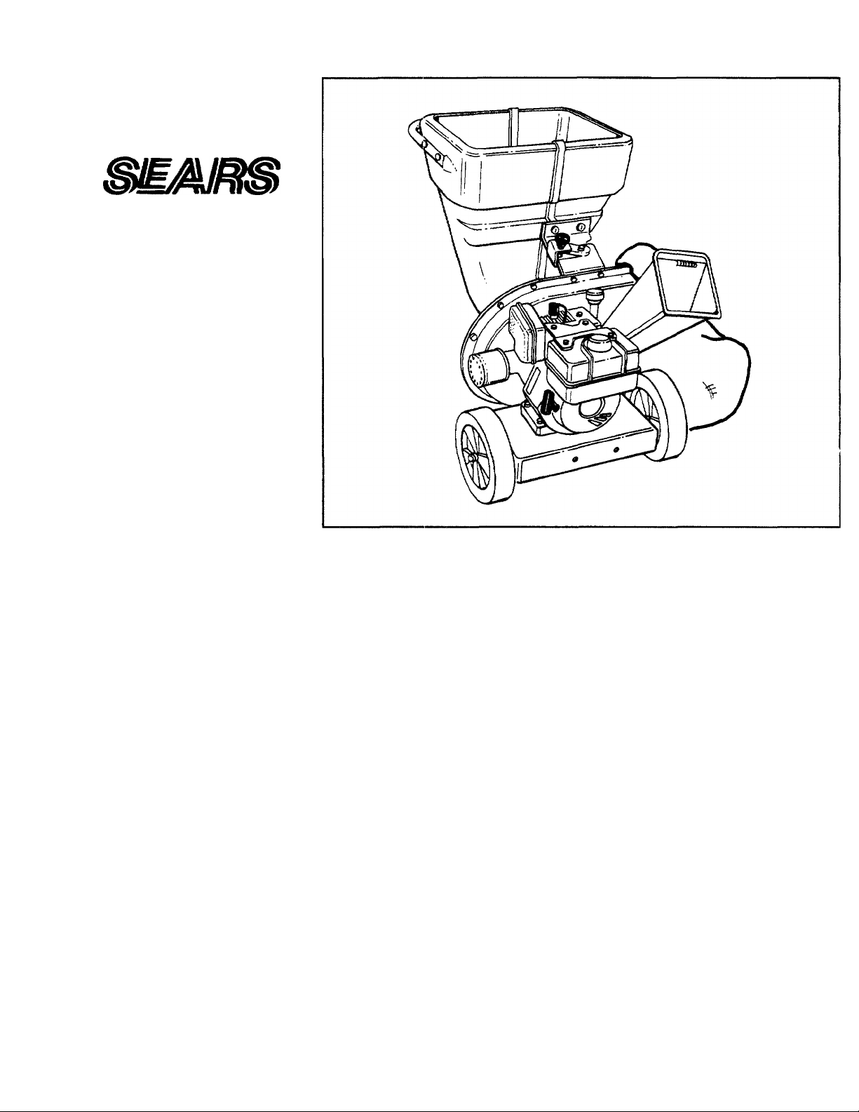
MULCHING AND BAGGING
CHIPPER-SHREDDER
Assembly
Oper atio n
Customer Responsibilities
Service and Adjustment
Repair Parts
Printed in U.S.A.
77O-0474H 3/93
Page 2

A
SAFETY RULES
WARNING: TO REDUCE THE POTENTIAL FOR ANY INJURY, COMPLY WITH THE FOLLOWING
SAFETY INSTRUCTIONS. FAILURE TO COMPLY WITH THE INSTRUCTIONS MAY RESULT IN
PERSONAL INJURY.
TRAINING
• Read this owner’s manual carefully in its entirety before
attempting to assemble or operate this machine. Be com
pletely familiar with the controls and the proper use of this
machine before operating it. Keep this manual in a safe
place for future and regular reference and for ordering
replacement parts.
• Children must never be allowed to operate this equipment.
• No one should operate this unit while intoxicated or while
taking medication that impairs the senses or reactions.
• This equipment should never be operated in the vicinity
of children, pets or other persons.
• Never run your machine in an enclosed area as the
exhaust from the engine contains carbon monoxide, which
is an odorless, tasteless and deadly poisonous gas.
• Never place your hands or any part of your body or cloth
ing inside the feeding chamber, discharge chute, or near
any moving part while the machine or engine is running.
• If it is necessary for any reason to Inspect or repair the
feeding chamber or any part of the machine where a mov
ing part can come in contact with your body or clothing,
stop the machine, allow it to cool, disconnect the spark
plug wire from the spark plug and move it away from the
spark plug before attempting such inspection or repair.
PREPARATION
• Wear safety glasses provided with your unit while operat
ing the chipper-shredder to prevent injury from any mate
rial which may be ejected out of the openings.
• Wear proper apparel. Avoid wearing loose fitting clothing.
Wear gloves when handling material.
• HANDLE GASOLINE WITH CARE as it is an extremely
flammable fuel.
• Check the fuel before starting the engine. Do not fill the
fuel tank indoors, while the engine is running, or while the
engine is still hot. Turn the unit off and let the engine cool
before refueling.
• Fuel your chipper-shredder in a clean area. Do not
smoke while refueling.
• Fuel tank cap must be secure at all times except during
refueling.
• Avoid spilling gasoline or oil. Wipe the unit clean of any
spilled fuel or oil.
• Store fuel and oil in approved containers, away from heat
or open flame, and out of reach of children.
• This machine should be operated only upon a level surface.
• Assure that all screws, nuts and bolts and other fasteners
are properly secured.
OPERATION
• When feeding shreddable material into this equipment,
be extremely careful that pieces of metal, rocks, bottles,
cans or other foreign objects are not included. Personal
injury or damage to the machine could result.
• If the cutting mechanism strikes any foreign object or if
your machine should start making an unusual noise or
vibration, immediately stop the engine, disconnect the
spark plug wire from the spark plug and move it away
from the spark plug. Allow the machine to stop and take
the following steps:
Inspect for damage.
Replace or repair any damaged parts.
Check for any loose parts and tighten to assure contin
ued safe operation.
• The engine must be kept clean of debris and other accu
mulations.
• Do not allow an accumulation of processed material to
build up in the discharge area as this will prevent proper
discharge and can result in kick-back from feed opening.
• Never place your hands or any other part of your body or
clothing inside the feeding chamber, discharge chute or
near any moving part while the engine is running.
• Keep all guards and deflectors in place and in good work
ing condition to assure continued safe operation.
• Always stand clear of the discharge area when operating
this machine.
• Keep your face and body back from the feed opening to
avoid accidental bounce back of any material.
• Do not over-reach. Keep proper balance and footing at all
times.
• The engine governor settings on your machine must not
be altered, changed, or tampered with. The governor
controls the maximum safe operating speeds and pro
tects the engine and all moving parts from damage
caused by overspeed.
• Do not transport machine while engine is running.
• Do not operate engine if air cleaner or cover directly over
carburetor air intake is removed, except for adjustment.
Removal of such parts could create a fire hazard.
MAINTENANCE AND STORAGE
• When this equipment is stopped for servicing, inspection,
storage or to change an accessory, make sure the spark
plug wire is disconnected from the spark plug and moved
away from the spark plug. The machine should be
allowed to cool down before making such inspection,
adjustments, service, etc. Maintain your machine with
care and keep it clean for the best and continued safe
operation.
• Do not use flammable solutions to clean the air filter.
• When not in use, your machine should be stored out of
the reach of children. Keep where gasoline fumes will not
reach an open flame or spark. For long periods of stor
age, refer to the “Storage" section of this manual.
A
LOOK FOR THIS SYMBOL TO POINT OUT
IMPORTANT SAFETY PRECAUTIONS. IT
MEANS—AHENTION!!! BECOME ALERT!!!
YOUR SAFETY IS INVOLVED.
Page 3

CONGRATULATIONS on your purchase of a Sears
Craftsman Chipper-Shredder. It has been designed, engi
neered and manufactured to give you the best possible
dependability and performance.
Should you experience any problem you cannot easily rem
edy, please contact your nearest Sears Service Center/
Department in the United States. We have competent, welltrained technicians and the proper tools to service or repair
this unit.
Please read and retain this manual. The instructions will
enable you to assemble and maintain your chipper-shredder
properly. Always observe the “SAFETY RULES.”
MODEL
NUMBER 247.795940
SERIAL
NUMBER_
PRODUCT SPECIFICATIONS
Horsepower: 5.0
Displacement:
Fuel Capacity:
Spark Plug (Gap .030 in.):
Ignition Air Gap: .0125 in.
12.00 cu. in.
1-7/8 Quarts
(Unleaded)
Champion
J-8C (or
Equivalent)
DATE OF
PURCHASE.
THE MODEL AND SERIAL NUMBERS WILL BE FOUND
ON A LABEL ATTACHED TO THE FRAME OF THE
CHIPPER-SHREDDER.
YOU SHOULD RECORD BOTH SERIAL NUMBER AND
DATE OF PURCHASE AND KEEP IN A SAFE PLACE
FOR FUTURE REFERENCE.
CUSTOMER RESPONSIBILITIES
Read and observe the safety rules.
Follow a regular schedule in maintaining, caring for
and using your chipper-shredder.
Follow the instructions under “Customer Respon
sibilities” and “Storage” sections of this Owner’s
Manual.
A Sears Maintenance Agreement is available on this
product. Contact your nearest Sears store for details.
WARNING: This unit is equipped with an internal combus
tion engine and should not be used on or near any unim
proved forest-covered, brush-covered or grass-covered land
unless the engine’s exhaust system is equipped with a
spark arrester meeting applicable local or state laws (if any).
If a spark arrester is used, it should be maintained in effec
tive working order by the operator.
In the State of California the above is required by law
(Section 4442 of the California Public Resources Code).
Other states may have similar laws. Federal laws apply on
federal lands. A spark arrester for the muffler is available
through your nearest Sears Authorized Service Center (See
the REPAIR PARTS section of this manual.)
MAINTENANCE AGREEMENT
WARRANTY
ONE YEAR LIMITED WARRANTY ON CRAFTSMAN GAS CHIPPER-SHREDDER
For one year from the date of purchase, when this Craftsman Chipper-Shredder is maintained, lubricated and
tuned up according to the instructions in the owner’s manual. Sears will repair, free of charge, any defect in
material and workmanship.
If this Craftsman Chipper-Shredder is used for commercial or rental purposes, this warranty applies for only 30
days from the date of purchase.
This warranty does not cover;
• Expendable items which become worn during normal use, such as blades, chipper blades, flails, air cleaners,
spark plugs and catcher bags.
• Repairs necessary because of operator abuse or negligence, including bent crankshafts and the failure to
maintain the equipment according to the instructions contained in the owner's manual.
WARRANTY SERVICE IS AVAILABLE BY RETURNING THE CRAFTSMAN CHIPPER-SHREDDER TO THE
NEAREST SEARS SERVICE CENTER/DEPARTMENT IN THE UNITED STATES. THIS WARRANTY
APPLIES ONLY WHILE THIS PRODUCT IS IN USE IN THE UNITED STATES.
This warranty gives you specific legal rights, and you may also have other rights which may vary from state to
state.
SEARS, ROEBUCK AND CO., D/817WA, Hoffman Estates, IL 60179
Page 4

TABLE OF CONTENTS
SAFETY RULES
PRODUCT SPECIFICATIONS.............
MAINTENANCE AGREEMENT
CUSTOMER RESPONSIBILITIES.
WARRANTY
INDEX...................................................
ASSEMBLY
OPERATION
Accessories
Adjustments:
Carburetor
Engine Speed
Assembly Instructions:
Catcher Bag....................
Chute Deflector
Catcher Bag
Controls...............................
Customer Responsibilities
Engine:
Lubrication
Maintenance
Starting
Stopping
Storage
Fuel......................................
Lubrication..........................
Maintenance:
Agreement
Schedule
Engine.............................
Chipper-Shredder
..................................
...........
.........................................
..........................................
........................................
A
........................
......................
.................
..............
C
........................
...................
E
.....................
...................
...........................
.........................
...........................
F
1
L
M
......................
.........................
.........
...2 CUSTOMER RESPONSIBILITIES
...3 STORAGE..........................................................................12
...3 SERVICE AND ADJUSTMENT
...3 TROUBLESHOOTING.......................................................15
...3 PARTS ORDERING/SERVICE
...4 REPAIR PARTS—CHIPPER-SHREDDER
...5 REPAIR PARTS—ENGINE
-10
INDEX
............................4
..........................
..........................14
............................
............................
............................
............................
..............
..........................10
...................
............................
............................
..........................
............................
..........................10
............................
..........................10
...................
..........................10
14
3, 10, 11
10, 11
12
10, 11
......................................
....................................
..........................................
..................
..........................................
0
Oil
.................................
Operating Tips
Repair/Replacement Parts
Responsibilities, Customer
5
5
5
6
9
7
8
3
Safety Rules
Sharpening...................
Spark Plug
Specifications
Storage
Table of Contents
Trouble Shooting
Unclogging...................
Unpacking
Warranty
.........................
.............
R
....................
..................
S
.................
...................
..............
T
........
.........
u
....................
w
......................
............................
.......................
....................
...............3, 10, 11
............................
...................
..........................11
............................
..........................12
............................
..........................15
..........................
............................
............................
10, 11
12-14
15
16, 17
17-20
8
7, 8
16-20
2
13, 14
3
4
12
5
3
CHIPPER-SHREDDER ACCESSORIES
These accessories were available when the chipper-shredder was purchased. They are also available at most
Sears retail outlets, catalog and service centers. Most Sears stores can order repair parts for you, when you pro
vide the model number of your chipper-shredder.
ENGINE CHIPPER-SHREDDER
Spark
Plug
Muffler
Engine
Oil
Gas Can Stabilizer
Page 5
ASSEMBLY INSTRUCTIONS
IMPORTANT: This unit is shipped WITHOUT GASO
LINE or OIL. After assembly, see operation section of
this manual for proper fuel and engine oil recommen
dations.
NOTE: To determine right and left hand sides of your
chipper-shredder, stand behind and face the hopper
(engine is at the front of the unit).
Your chipper-shredder has been completely assem
bled at the factory, except for the chute deflector and
the catcher bag. A pair of safety glasses are also
included in the carton.
Spacers
(Inside
Hinge)
FIGURE 1.
Hex Bolt
Chute
Deflector
TO REMOVE CHIPPER-SHREDDER FROM CARTON
Cut the corners of the carton. Remove all packing
inserts. Roll chipper-shredder out of the carton. Make
certain all parts, literature and the safety glasses have
been removed before the carton is discarded.
TOOLS REQUIRED FOR ASSEMBLY
(2) 7/16" or Adjustable Wrenches
HOW TO SET-UP YOUR CHIPPER-SHREDDER
MAKE CERTAIN THE SPARK PLUG
WIRE IS DISCONNECTED AND MOVED
AWAY FROM THE SPARK PLUG
A
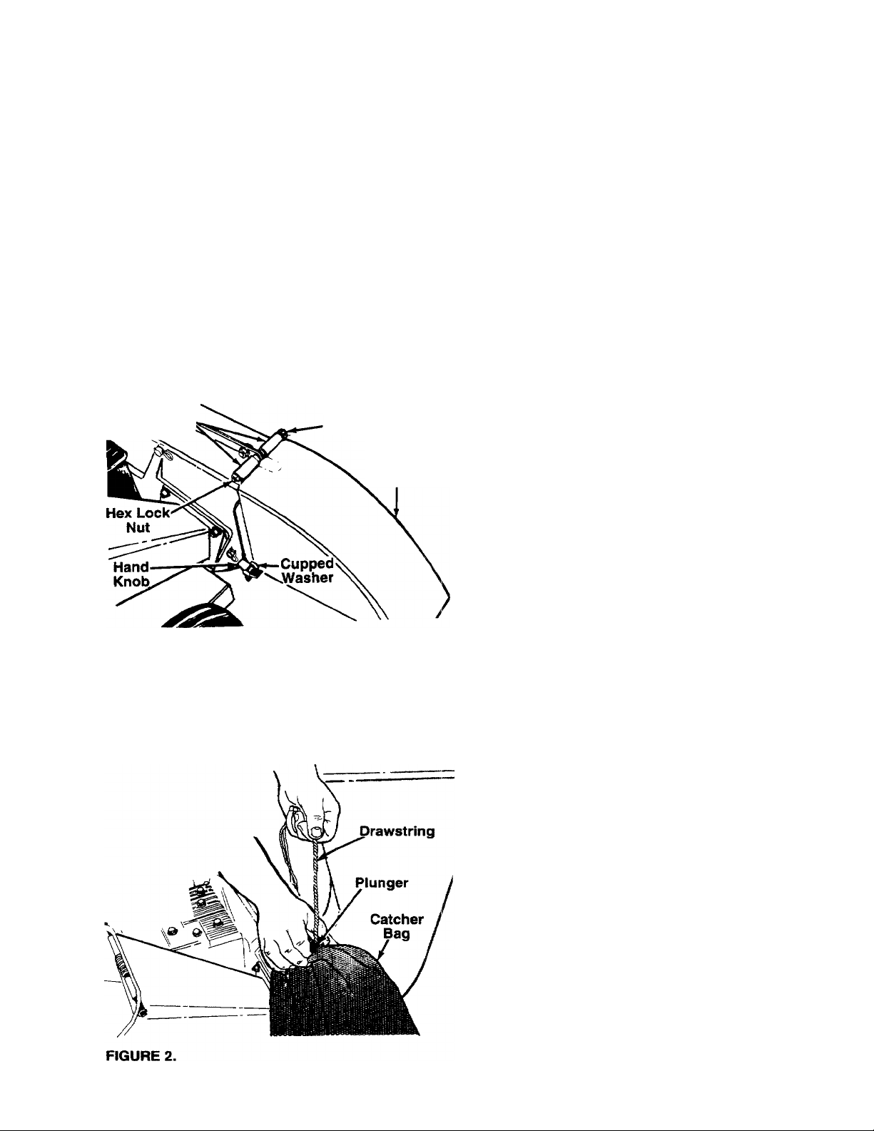
ATTACHING THE CHUTE DEFLECTOR
• Remove the hand knobs and cupped washers from
each side of the discharge opening on the left side
of the shredder.
• Remove the hex lock nut, two spacers and hex bolt
from inside the hinge on top of the discharge open
ing. Do not remove one spacer from the hex bolt.
• Place the chute deflector in position on the dis
charge opening. Insert bolt through hinge on chute
deflector and housing (spacer fits inside hinge).
• Place second spacer over the hex bolt, inside the
other part of hinge. Secure with hex lock nut.
Tighten securely.
• Secure both sides of the chute deflector to the
housing using hand knobs and cupped washers
(cupped side of washers go against chute deflec
tor).
BEFORE ASSEMBLING THE CHIPPERSHREDDER.
ATTACHING THE CATCHER BAG
Your chipper-shredder is equipped with a catcher bag
to catch the shredded material.
• To attach bag, place bag opening over the chute
deflector so it completely covers chute opening.
Depress plunger on drawstring, pull on drawstring
until bag is tight around chute opening. Release
plunger to lock it into position. See figure 2.
Page 6
OPERATION
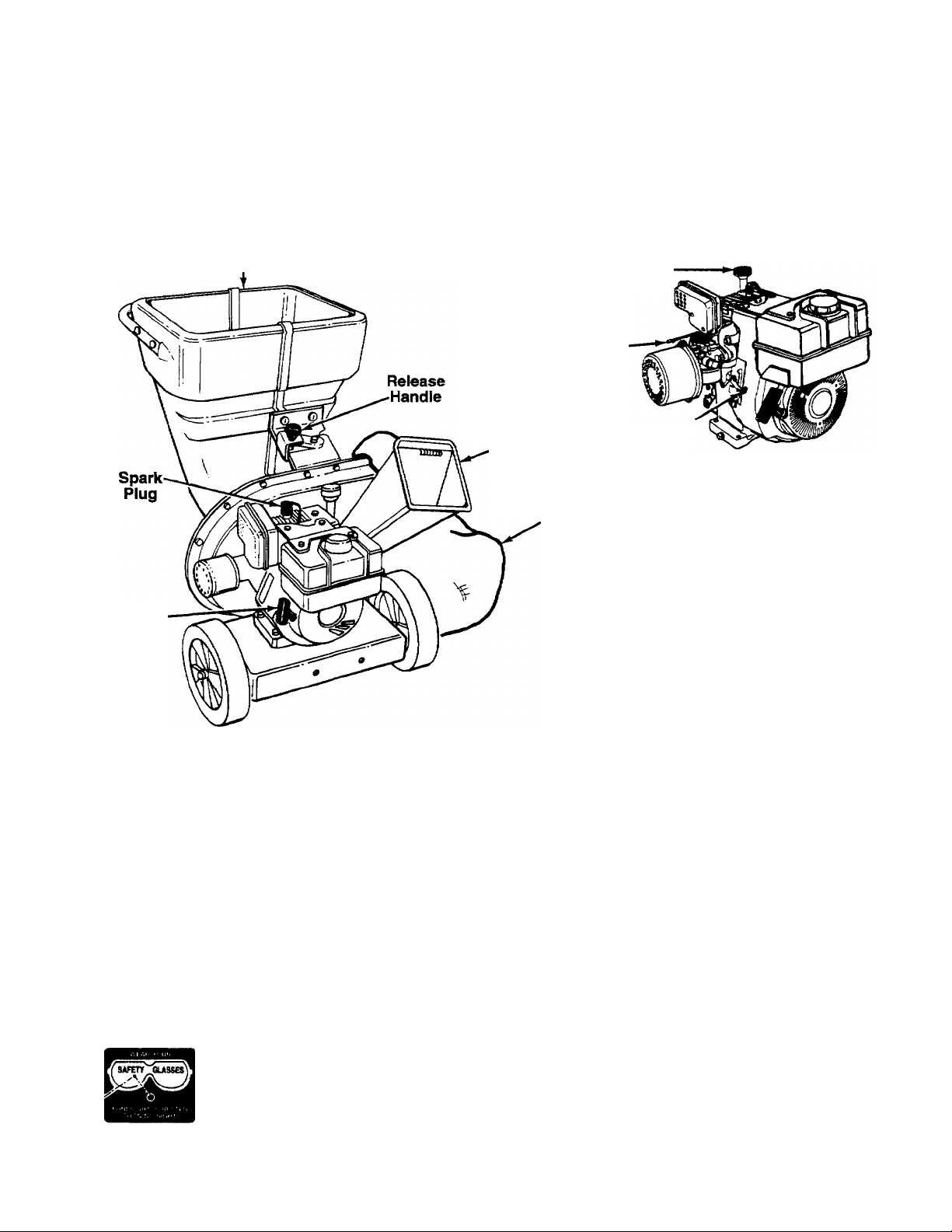
KNOW YOUR CHIPPER-SHREDDER
READ THIS OWNER’S MANUAL AND SAFETY RULES BEFORE OPERATING YOUR CHIPPER-SHREDDER.
Compare the illustrations with your chipper-shredder to famiiiarize yourself with the location of various controls
and adjustments. Save this manual for future reference.
Hopper
Assembly
Oil Fill-
Dipstick
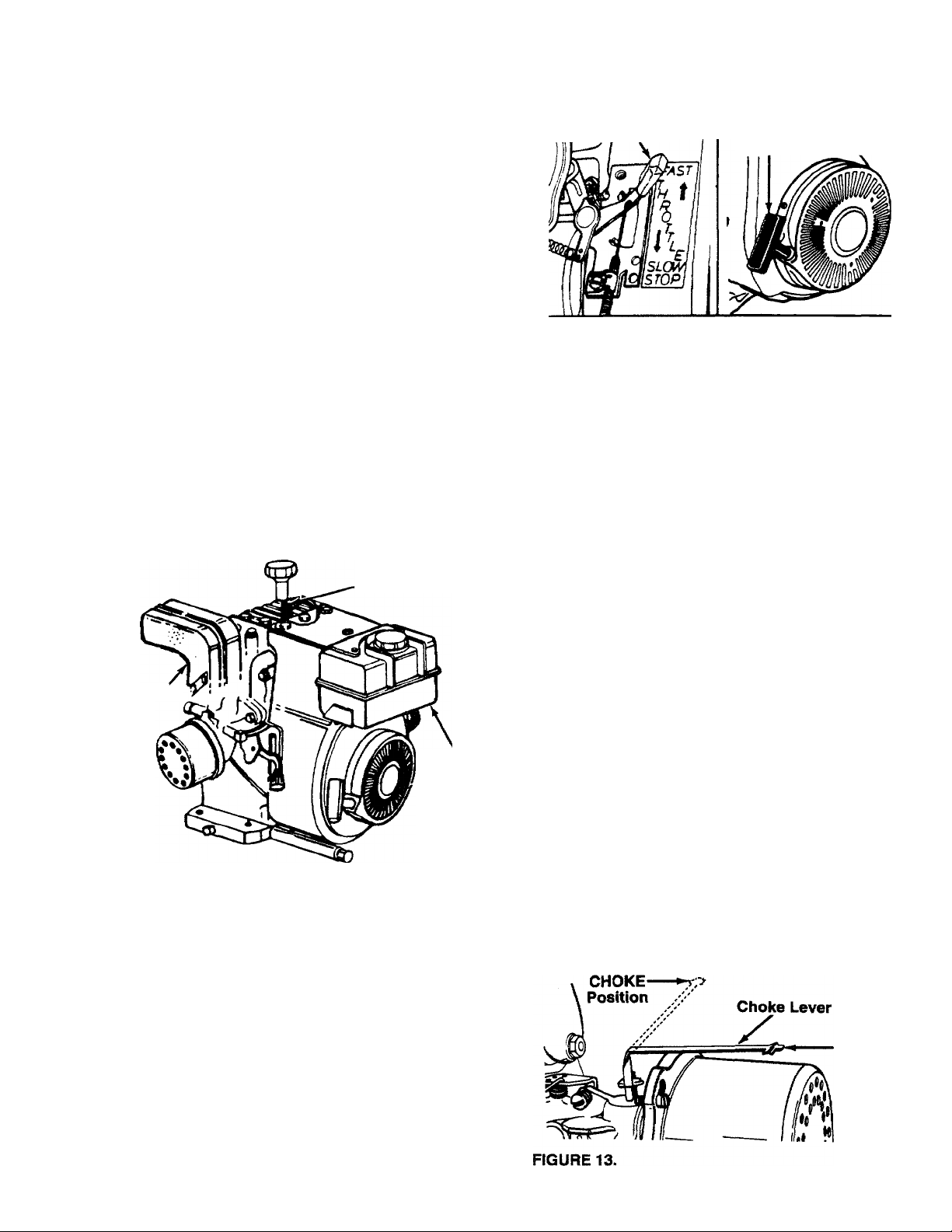
Choke
Lever
Chipper
Chute
Catcher
Bag
Starter
Handle
FIGURE 3.
Throttle
Control
MEETS ANSI SAFETY STANDARDS
Sears chipper-shredders conform to the safety standards of the American National Standards Institute.
OPERATING CONTROLS (See figures 3 and 4)
CHOKE LEVER—Used to enrich the fuel mixture in
the carburetor when starting a cold engine.
STARTER HANDLE—Used to manually start the
engine.
THROTTLE CONTROL—Controls engine speed and
stops the engine.
RELEASE HANDLE—Used to release the hopper
when lowering to the ground.
FIGURE 4.
BEFORE USING YOUR CHIPPER-SHREDDER, AGAIN REFER TO THE “SAFETY RULES”
PAGE 2 OF THIS MANUAL. ALWAYS BE CAREFUL.
The operation of any chipper-shredder can result in foreign objects being thrown into
the eyes, which can result in severe eye damage. Always wear the safety glasses pro
vided with the chipper-shredder or eye shields before chipping or shredding, or while
performing any adjustments or repairs. We recommend Wide Vision Safety Mask for
over spectacles or standard glasses available at Sears Retail or Catalog Stores.
AS SHOWN ON
Page 7
TO STOP ENGINE
• Move throttle control lever to OFF position. See fig
ure 4.
• Disconnect spark plug wire and move away from
spark plug to prevent accidental starting while
equipment is unattended.
HOW TO USE YOUR CHIPPER-SHREDDER
Do not attempt to shred or chip any material other
than vegetation found in a normal yard (i.e., branches,
leaves, twigs, etc,).
FIGURE 5.
WARNING: THE CHIPPER-SHREDDER
DISCHARGES MATERIALS WITH CON
A
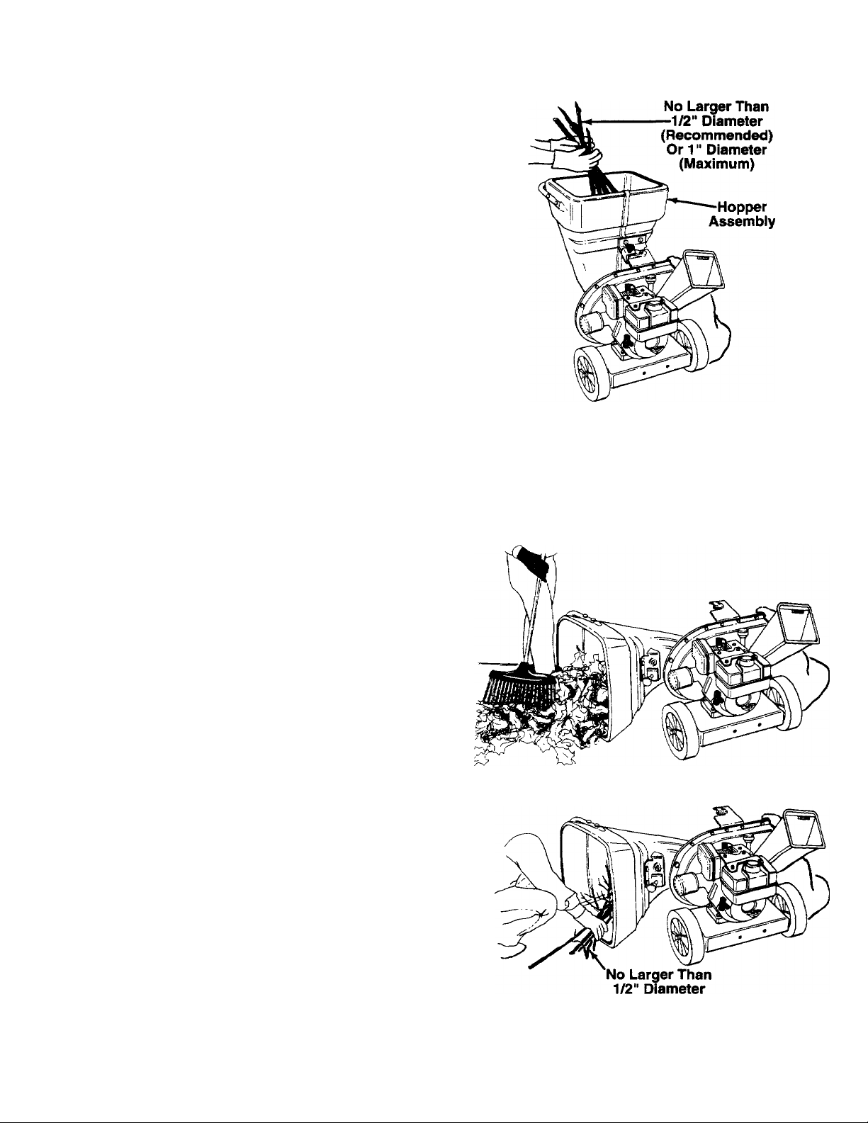
The chipper-shredder is designed for three different
methods of operation.
• Leaves and small branches up to 1/2" diameter
(recommended) or 1“ diameter (maximum) can be
fed into the hopper assembly when it is in the
raised position. See figure 5. If it becomes neces
sary to push material into the chipper-shredder,
use a small diameter stick—NOT YOUR HANDS.
The stick should be small enough that it will be
ground up if gets into the impeller assembly.
SIDERABLE VELOCITY. KEEP AWAY
FROM THE AREA AROUND THE CHUTE
DEFLECTOR. ALWAYS STOP THE
ENGINE AND DISCONNECT THE SPARK
PLUG WIRE WHEN REMOVING OR
ATTACHING THE BAG WHEN CHANGING
CONTAINERS OR WHEN REMOVING THE
SHREDDED MATERIAL. WEAR SAFETY
GLASSES AND GLOVES WHENEVER
USING YOUR CHIPPER-SHREDDER.
• Leaves and small twigs can be raked into the hop
per assembly when the hopper assembly is low
ered to the ground. See figure 6. Small branches
up to 1/2" diameter (recommended) or 1" diam
eter (maximum) can also be fed into the hopper
assembly in this position. See figure 7.
FIGURE 6.
A
WARNING: DO NOT PUT MATERIAL
LARGER THAN 1/2" IN DIAMETER (REC
OMMENDED) or 1" DIAMETER (MAXI
MUM) INTO THE HOPPER ASSEMBLY.
MATERIAL UP TO A MAXIMUM OF 3" IN
DIAMETER MATERIAL MAY BE FED
INTO THE CHIPPER CHUTE. DO NOT
ATTEMPT TO SHRED OR CHIP ANY
MATERIAL LARGER THAN 3" IN DIAME
TER. PERSONAL INJURY OR DAMAGE
TO THE MACHINE COULD RESULT.
(Recommended)
Or 1" Diameter
(Maximum)
FIGURE 7.
Page 8
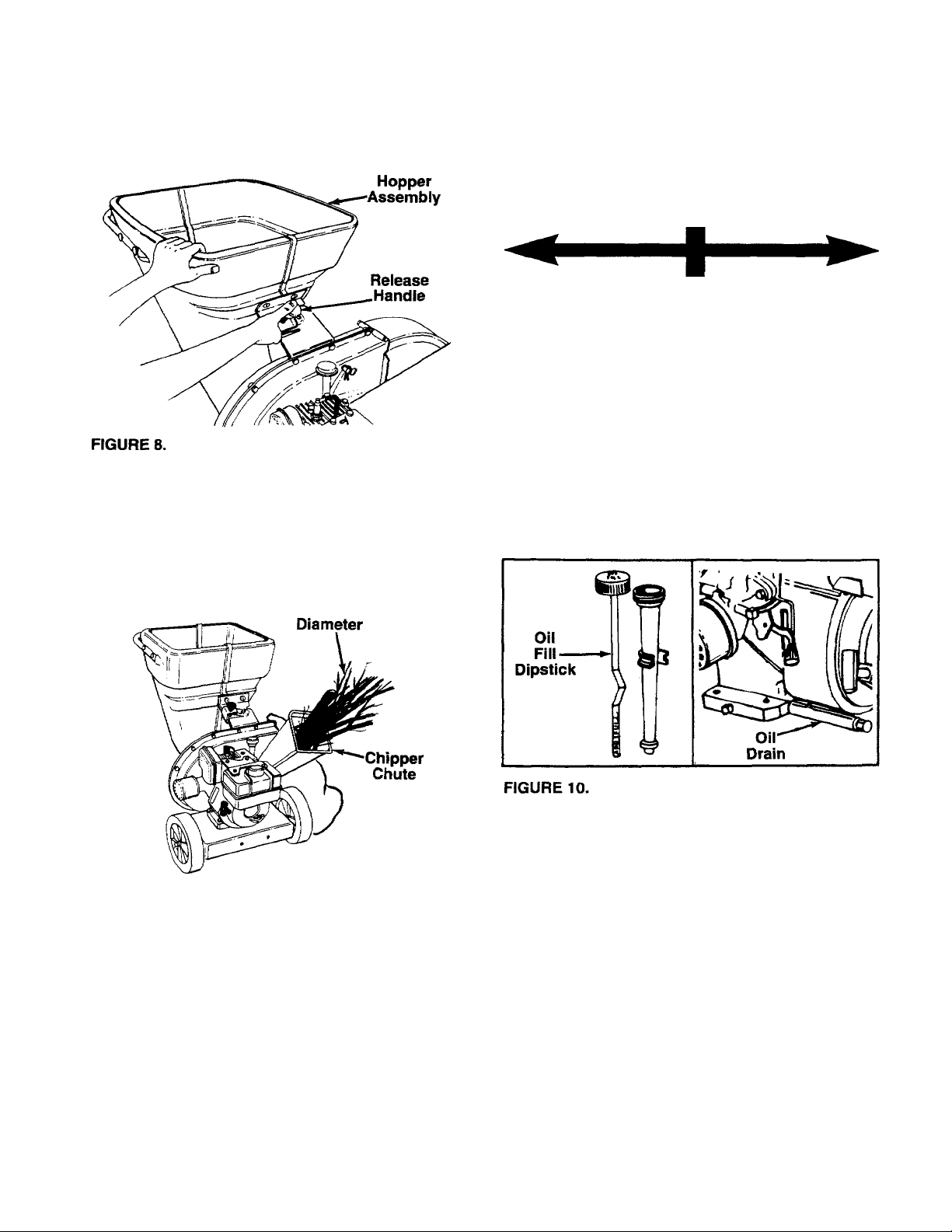
To lower the hopper assembly to the ground, use
one hand to grasp the top of the hopper assembly.
Push down on the release handle, and pivot the
hopper assembly to the right. See figure 8.
GAS AND OIL FILL-UP
OIL
Only use high quality detergent oil rated with API ser
vice classification SG. Select the oil’s viscosity grade
according to your expected operating temperature.
Colder
------------------------
32°F
-----------------
► Warmer
• Bulky material, such as stalks or heavy branches,
up to 3" in diameter, should be fed into the chipper
chute. See figure 9.
WARNING: MAKE CERTAIN THE CHIP
PER CHUTE DOOR IS CLOSED WHEN
A
NOT IN USE.
3" Maximum
5W30
NOTE: Although multi-viscosity oils (5W30, 10W30,
etc.) improve starting in cold weather, these multi
viscosity oils will result in increased oil consumption
when used above 32°F. Check your oil level more fre
quently to avoid possible engine damage from run
ning low on oil.
• Fill engine with oil as follows. Remove oil fill dip
stick. See figure 10. With chipper-shredder level,
use a funnel to fill engine with oil to FULL mark on
dipstick. Capacity is approximately 1-1/4 pints. Be
careful not to overfill. Tilt chipper-shredder toward
the left (from behind the hopper), then re-level.
Check oil level. Refill to FULL mark on dipstick if
necessary. Replace dipstick and tighten.
SAE30
FIGURE 9.
IMPORTANT: There is a flail screen located inside
the housing in the discharge area. If the flail screen
becomes clogged, remove and clean as instructed in
the Service and Adjustments section. For best per
formance, it is important to keep the shredding blade
and the chipper blades sharp. If the composition of
the material being discharged changes (becomes
stringy, etc.) or if the rate at which the material is dis
charged slows down considerably, it is likely that the
shredding blade and/or chipper blades are dull and
need to be sharpened or replaced. Refer to Service
and Adjustments section.
GAS
• Remove fuel cap and fill fuel tank with about 1-7/8
quarts of clean, fresh, lead-free grade automotive
gasoline. DO NOT use Ethyl or high octane gaso
line. Be certain container is clean and free from
rust or foreign particles. Never use gasoline that
may be stale from long periods of storage in the
container. Replace fuel cap.
WARNING: DO NOT FILL CLOSER THAN
1/2 INCH OF TOP OF FUEL TANK TO
A
PREVENT SPILLS AND TO ALLOW FOR
FUEL EXPANSION. IF GASOLINE IS
ACCIDENTLY SPILLED, MOVE CHIPPERSHREDDER AWAY FROM AREA OF
SPILL. AVOID CREATING ANY SOURCE
OF IGNITION UNTIL GASOLINE VAPORS
HAVE DISAPPEARED.
Page 9
Check the fuel level periodically to avoid running out
of gasoline while operating the chipper-shredder. If
the unit runs out of gas as it is shredding or chipping,
it may be necessary to unclog the unit before it can be
restarted. Refer to “Removing the Flail Screen" in
SERVICE AND ADJUSTMENT section.
WARNING: EXPERIENCE INDICATES THAT ALCO
HOL BLENDED FUELS (CALLED GASOHOL OR
USING ETHANOL OR METHANOL) CAN ATTRACT
MOISTURE WHICH LEADS TO SEPARATION AND
FORMATION OF ACIDS DURING STORAGE.
ACIDIC GAS CAN DAMAGE THE FUEL SYSTEM
OF AN ENGINE WHILE IN STORAGE. TO AVOID
ENGINE PROBLEMS, THE FUEL SYSTEM
SHOULD BE EMPTIED OR TREATED WITH FUEL
STABILIZER BEFORE STORAGE FOR 30 DAYS
OR LONGER. USE FRESH FUEL NEXT SEASON.
SEE “STORAGE” SECTION FOR ADDITIONAL
INFORMATION.
NEVER USE ENGINE OR CARBURETOR CLEAN
ER PRODUCTS IN THE FUEL TANK OR PERMA
NENT DAMAGE MAY OCCUR.
Spark Plug,
Wire and
Rubber Boot
Throttle Control
FIGURE 12.
• Move choke lever to CHOKE position (See figure
13.).
• Grasp starter handle (see figure 12) and pull rope
out slowly until engine reaches start of compres
sion cycle (rope will pull slightly harder at this
point). Let the rope rewind slowly.
NOTE: A noise will be heard when finding the start of
the compression cycle. This noise is caused by the
flails and fingers which are part of the shredding mech
anism falling into place, and should be expected. In
addition, the flails and fingers will be noisy after the
engine is started, until the impeller reaches full speed.
Starter
Handle
Muffler
FIGURE 11.
TO START ENGINE
WARNING: BE SURE NO ONE OTHER
THAN THE OPERATOR IS STANDING
A
NEAR THE CHIPPER-SHREDDER WHILE
STARTING OR OPERATING. DO NOT
OPERATE THIS CHIPPER-SHREDDER
UNLESS THE CHUTE DEFLECTOR HAS
BEEN PROPERLY INSTALLED AND IS
SECURED WITH THE HAND KNOBS.
Fuel
Tank
• Pull rope with a rapid, continuous, full arm stroke.
Keep a firm grip on start handle. Let rope rewind
slowly. Do not let starter handle snap back against
starter.
• Repeat preceding two instructions until engine
fires. When engine starts, move choke lever on
engine halfway between CHOKE and RUN.
NOTE: If engine does not fire after three attempts,
move choke lever halfway between CHOKE and RUN
position and try again. See figure 13.
• Move throttle control to IDLE position for a few min
utes warm-up. Move choke lever to RUN position
as engine warms up.
NOTE: In order to idle smoothly, a new engine may
require 3 to 5 minutes running above slow idle speed.
Idle speed has been adjusted to be correct after this
break-in period.
OFF
Position
• Attach spark plug wire and rubber boot to spark
plug if necessary. See figure 11.
• Place the throttle control lever in FAST position.
See figure 12.
Page 10
TO STOP ENGINE
• Move throttle control lever to OFF position. See fig
ure 13.
CUSTOMER RESPONSIBILITIES
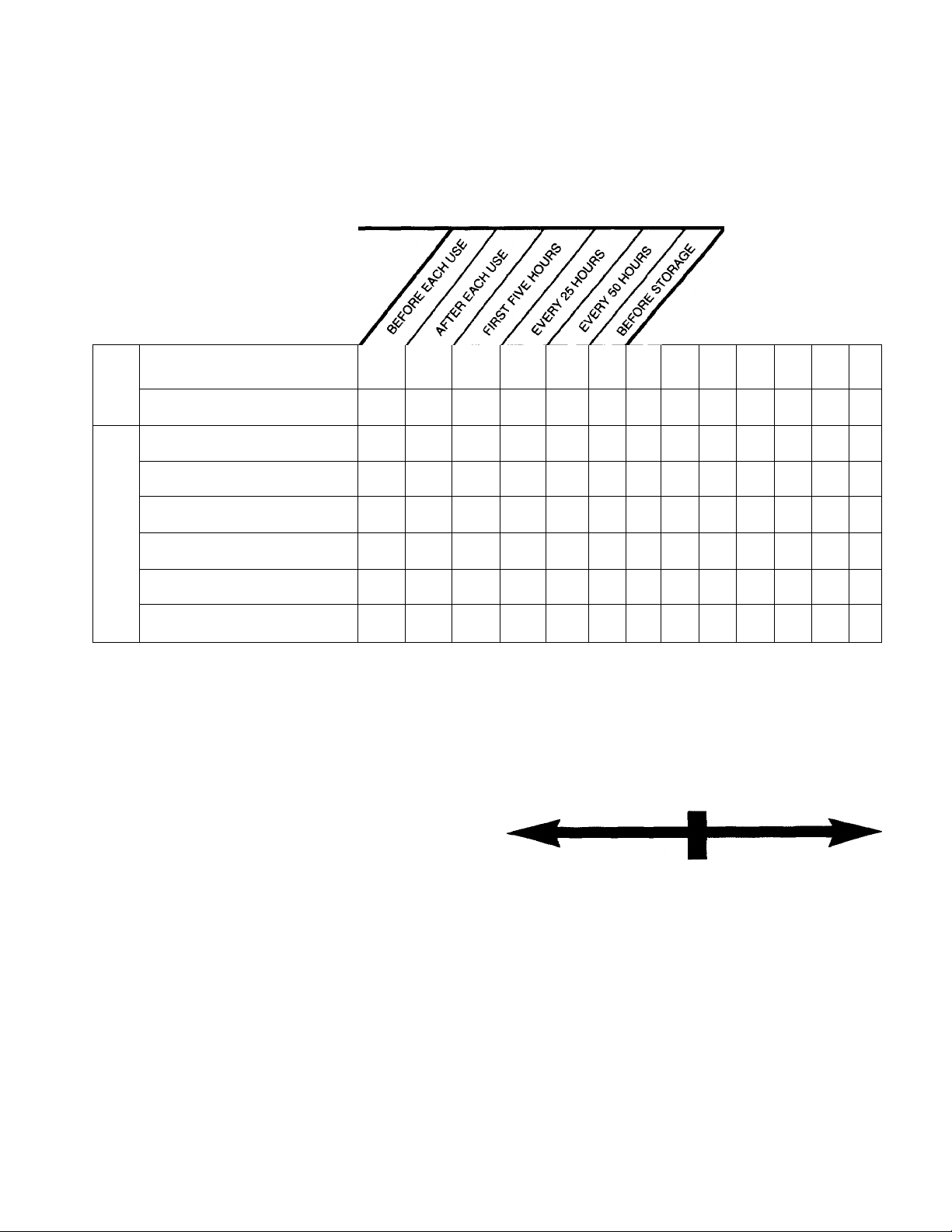
MAINTENANCE SCHEDULE
FILL IN DATES
AS YOU COMPLETE
REGULAR SERVICE
h—
o
Oil Pivot Points
=)
o
o
tc
Clean Shredder
a.
Check Engine Oil
Change Engine Oil
V
t
Disconnect spark plug wire and move away from
spark plug to prevent accidental starting while
equipment is unattended.
SERVICE DATES
V
V
V
UJ
Service Air Cleaner
z
o
z
Clean Engine Cylinder
ai
Spark Plug
Muffler
V CHECK
GENERAL RECOMMENDATIONS
WARNING: ALWAYS STOP THE ENGINE
AND DISCONNECT THE SPARK PLUG
A
• Periodically check all fasteners and be sure they
are tight.
• Follow the Maintenance Schedule above.
WIRE BEFORE PERFORMING ANY
MAINTENANCE OR ADJUSTMENTS.
CHIPPER-SHREDDER
LUBRICATION
Lubricate the pivot points on the release handle, hop
per assembly, chute deflector and chipper chute once
a season using a light oil.
CLEANING
• The chipper-shredder may be cleaned by running
water from a hose through the hopper assembly
and chipper chute with the engine running. Allow
the chipper-shredder to dry thoroughly.
• Wash the bag periodically with water. Allow to dry
thoroughly in the shade. Do not use heat.
V
V
V
V
V
ENGINE
ENGINE OIL
Only use high quality detergent oil rated with API ser
vice classification SG. Select the oil’s viscosity grade
according to your expected operating temperature.
Colder ------------------------ 32°F
5W30
NOTE: Although multi-viscosity oils (SE30, 10W30,
etc.) improve starting in cold weather, these multi- vis
cosity oils will result in increased oil consumption
when used above 32°F. Check your oil level more fre
quently to avoid possible engine damage from run
ning low on oil.
Your four-cycle engine will normally consume some
oil—therefore, check engine oil level regularly approx
imately every five hours of operation and before each
usage. Stop engine and wait several minutes before
checking oil level. With engine level, the oil must be to
FULL mark on dipstick (refer to figure 10). Change
engine oil after the first five hours of operation, and
every twenty-five hours thereafter.
-----------------
SAE30
► Wanner
10
Page 11
To Drain Oil:
• Drain oil while engine is warm.
a. Remove oil drain cap. Refer to figure 10. Catch
oil in a suitable container.
b. When engine is drained of all oil, replace drain
cap securely.
• Refill with fresh oil. Refer to GAS AND OIL FILL
UP section.
• Replace dipstick.
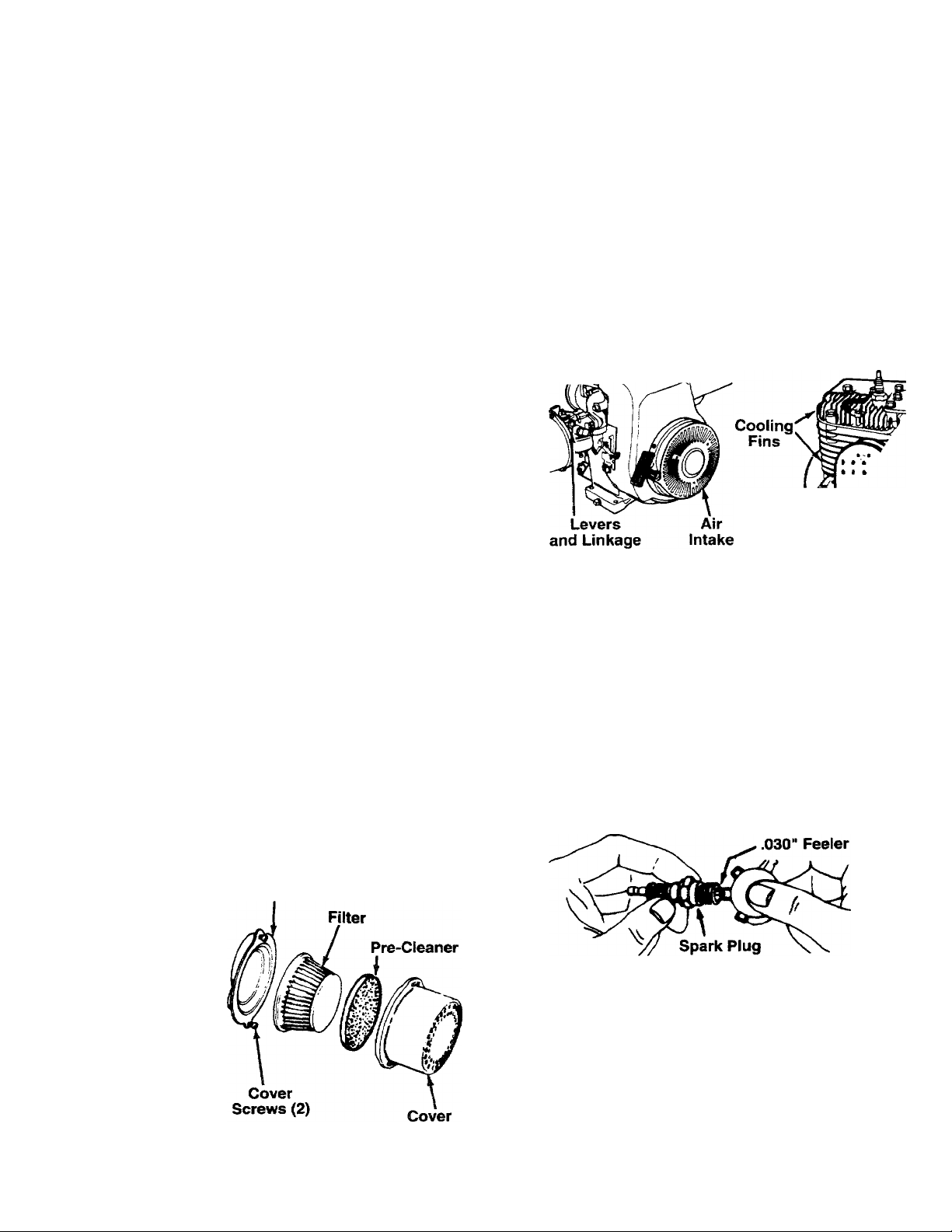
AIR CLEANER
The air cleaner prevents damaging dirt, dust, etc.,
from entering the carburetor and being forced into the
engine and is important to engine life and per
formance.
Never run your engine without air cleaner com
pletely assembled.
To Service Air Cleaner:
Service pre-cleaner after every 25 hours of use, or at
least once a season. Service cartridge every 100 hours
of use, or at least once a season. Sen/ice pre-cleaner
and cartridge more often under dusty conditions.
• Loosen (do not remove) the two screws which
secure the cover.
• Turn the cover counterclockwise and remove it
from the base.
• Carefully remove pre-cleaner and cartridge.
• Clean the inside of base and cover thoroughly.
• Clean cartridge by tapping gently on a flat surface.
If very dirty, replace cartridge and pre-cleaner or
clean as follows;
Wash in a low or non-sudsing detergent and warm
water solution. CAUTION: Do not use petroleum
solvents such as kerosene to clean cartridge.
Rinse thoroughly with flowing water from inside out
until water is clear.
Allow cartridge to stand and air dry thoroughly
before using. DO NOT OIL CARTRIDGE OR PRE
CLEANER. DO NOT USE PRESSURIZED AIR TO
CLEAN OR DRY CARTRIDGE.
• Reassemble cover to engine. Tighten the two
screws securely.
CLEAN ENGINE
Clean engine periodically, Remove dirt and debris
with a cloth or brush. Cleaning with a forceful spray of
water is not recommended as water could contami
nate the fuel system.
Yearly or every 25 hours, whichever occurs first,
remove the blower housing and clean the areas
shown in figure 15 to avoid overspeeding, overheating
and engine damage, Clean more often if necessary.
WARNING: PERIODICALLY CLEAN MUF
FLER AREA TO REMOVE ALL GRASS,
A
DIRT AND COMBUSTIBLE DEBRIS.
FIGURE 15.
SPARK PLUG
The spark plug should be cleaned and the gap reset
to .030" at least once a season or every 50 hours of
operation. See figure 16. Spark plug replacement is
recommended at the start of each season. Refer to
engine parts list for correct spark plug type.
NOTE: Do not sandblast spark plug. Spark plug
should be cleaned by scraping or wire brushing and
washing with a commercial solvent.
FIGURE 14.
Base
FIGURE 16.
MUFFLER
Do not operate the chipper-shredder without a muffler
or tamper with the exhaust system. Damaged mufflers
or spark arresters could create a fire hazard. Inspect
periodically, and replace if necessary. If your engine
is equipped with a spark arrester screen assembly,
remove every 50 hours for cleaning and inspection.
Replace if damaged.
11
Page 12

STORAGE
Prepare your chipper-shredder for storage at the end
of the season or if the unit will not be used for 30 days
or more.
WARNING; NEVER STORE MACHINE
WITH FUEL IN THE FUEL TANK INSIDE
A
NOTE: A yearly check-up by your local Sears Service
Center is a good way to make certain your chippershredder will provide maximum performance for the
next season.
OF BUILDING WHERE FUMES MAY
REACH AN OPEN FLAME OR SPARK, OR
WHERE IGNITION SOURCES ARE
PRESENT SUCH AS HOT WATER AND
SPACE HEATERS, FURNACES, CLOTHES
DRYERS, STOVES, ELECTRIC MOTORS,
ETC.
CHIPPER-SHREDDER
• Clean the chipper-shredder thoroughly.
• Wipe unit with an oiled rag to prevent rust (use a
light oil or silicone).
ENGINE
IMPORTANT: IT IS IMPORTANT TO PREVENT
GUM DEPOSITS FROM FORMING IN ESSENTIAL
FUEL SYSTEM PARTS SUCH AS CARBURETOR,
FUEL FILTER, FUEL HOSE, OR TANK DURING
STORAGE. ALSO, EXPERIENCE INDICATES THAT
ALCOHOL BLENDED FUELS (CALLED GASOHOL
OR USING ETHANOL OR METHANOL) CAN
ATTRACT MOISTURE WHICH LEADS TO SEPARA
TION AND FORMATION OF ACIDS DURING STOR
AGE. ACIDIC GAS CAN DAMAGE THE FUEL SYS
TEM OF AN ENGINE WHILE IN STORAGE.
• Drain the fuel tank.
• Start the engine and let it run until the fuel lines and
carburetor are empty.
• Never use engine or carburetor cleaner products in
the fuel tank or permanent damage may occur.
• Use fresh fuel next season.
NOTE: Fuel stabilizer is an acceptable alternative in
minimizing the formation of fuel gum deposits during
storage. Add stabilizer to gasoline in fuel tank or stor
age container. Always follow the mix ratio found on
stabilizer container. Run engine at least 10 minutes
after adding stabilizer to allow the stabilizer to reach
the carburetor. Do not drain the gas tank and carbure
tor if using fuel stabilizer.
• Drain all the oil from the crankcase (this should be
done after the engine has been operated and is still
warm) and refill the crankcase with fresh oil.
• If you have drained the fuel tank, protect the inside
of the engine as follows. Remove spark plug, pour
approximately 1/2 ounce (approximately one table
spoon) of engine oil into cylinder and crank slowly
to distribute oil. Replace spark plug.
OTHER
• Do not store gasoline from one season to another.
• Replace your gasoline can if your can starts to rust.
Rust and/or dirt in your gasoline will cause problems.
• Store unit in a clean, dry area. Do not store next to
corrosive materials, such as fertilizer.
NOTE: If storing in an unventilated or metal storage
shed, be certain to rustproof the equipment by coating
with a light oil or silicone.
SERVICE & ADJUSTMENT
WARNING; ALWAYS STOP ENGINE AND
DISCONNECT SPARK PLUG WIRE AND
A
REMOVING THE FLAIL SCREEN
If the discharge area becomes clogged, remove the
flail screen and clean area as follows.
• Stop the engine, make certain the chipper-shredder
has come to a complete stop and disconnect spark
plug wire from the spark plug before unclogging the
chute.
MOVE IT AWAY FROM SPARK PLUG
BEFORE PERFORMING ANY ADJUST
MENTS OR REPAIRS.
• Loosen the two hand knobs on each side of the
chute deflector. Lift the chute deflector up, and tie it
out of the way.
• Remove two hairpin clips from the clevis pins which
extend through the housing. Remove the clevis
pins. Lift the flail screen from inside the housing.
See figure 17.
• Clean the screen by scraping or washing with
water. Reinstall the screen.
NOTE: Be certain to reassemble the flail screen with
the curved side down as shown in figure 17.
12
Page 13

Chute Deflector
Hand Knobs
FIGURE 17.
SHARPENING OR REPLACING THE BLADES
CHIPPER BLADES
• Disconnect spark plug wire and move it away from
spark plug.
• Remove the flail screen as instructed in previous
section.
• Remove the chipper chute by removing three hex
nuts and washers. A 1/2" wrench is required. See
figure 17.
NOTE: When reassembling, the cupped washer goes
on the bottom of the chipper chute with the cupped
side against the chute.
• Rotate the impelier assembly by hand until you
locate one of the chipper blades in the chipper
chute opening. Remove the blade, using a 3/16"
alien wrench on the outside of the blade and 1/2"
wrench on the impeller assembly (inside the hous
ing). See figure 18.
• Remove the other blade in the same manner.
Replace or sharpen blades. If sharpening, make cer
tain to remove an equal amount from each blade.
Reassemble in reverse order.
Make certain blades are reassembled with the sharp
edge facing the direction shown in figure 18 (sharp
edge is assembled toward the slotted opening in the
impeller assembly).
SHREDDING BLADE
The shredding blade may be removed for sharpening
or replacement as follows.
• Disconnect spark plug wire and move it away from
spark plug.
• Lower the hopper assembly. Block up the housing.
See figure 19.
• Remove the six hex lock nuts and lock washers
from the housing weld bolts using a 1/2“ wrench.
Separate the chipper-shredder into two halves.
• Remove the back-up plate.
NOTE: When reassembling, make certain the open
ing on the back-up plate is toward the bottom of the
unit. The back-up plate may be reversed to provide a
new cutting edge.
Allen
Screws
FIGURE 18.
Torque
Wrench
FIGURE 19.
Loosen the two hand knobs and cupped washers
which secure the chute deflector, and raise the
chute deflector.
Insert a 1/2" or 3/4" diameter pipe through the flail
screen into the impeller to keep it from turning, or
remove the flail screen and insert a piece of wood
(2 X 4) into the chute opening.
Remove the two outside screws on the blade,
using a 3/16" alien wrench and a 1/2" wrench.
Remove the blade by removing the center bolt, lock
washer and flat washer.
13
Page 14

NOTE: Use caution when removing the blade to avoid
contacting the weld bolts on the housing.
• When sharpening the blade, follow the original
angle of grind as a guide. It is extremely important
that each cutting edge receives an equal amount of
grinding to prevent an unbalanced blade. An unbal
anced blade will cause excessive vibration when
rotating at high speeds and may cause damage to
the unit.
• The blade can be tested for balance by balancing it
on a round shaft screwdriver or nail. Remove metal
from the heavy side until it is balanced evenly. See
figure 20.
CARBURETOR ADJUSTMENT
WARNING: IF ANY ADJUSTMENTS ARE
MADE TO THE ENGINE WHILE THE
A
The carburetor has been pre-set at the factory and
should not require adjustment. However, if your
engine does not operate properly due to suspected
carburetor problems, take your shredder to your near
est SEARS Service Center.
ENGINE IS RUNNING (E.G. CARBURE
TOR), KEEP CLEAR OF ALL MOVING
PARTS. BE CAREFUL OF HEATED SUR
FACES AND MUFFLER.
ENGINE SPEED
Your engine speed has been factory set. Do not
attempt to increase engine speed or it may result in
personal injury. If you believe the engine is running
too fast or too slow, take your chipper-shredder to the
nearest SEARS Service Center for repair and adjust
ment.
• When reassembling the blade, tighten to between
550 and 650 inch pounds, or lacking torque
wrench, tighten securely.
FLAILS
The flails, located inside the housing, may be
reversed when they become dull. It is suggested that
this procedure be performed by your nearest Sears
Service Department.
14
Page 15

TROUBLE SHOOTING
PROBLEM
Engine fails to start • Fuel tank empty, or stale fuel.
Loss of power;
operation erratic
Engine overheats • Carburetor not adjusted
Too much vibration
Unit does not
discharge
Rate of discharge
slows considerably or
composition of
discharged material
changes
POSSIBLE CAUSE(S)
• Spark plug wire disconnected.
• Faulty spark plug.
• Spark plug wire loose.
• Unit running on CHOKE.
• Blocked fuel line or stale fuel.
• Water or dirt in fuel system.
• Carburetor out of adjustment.
• Dirty air cleaner.
properly.
• Engine oil level low.
• Loose parts or damaged
impeller.
• Discharge chute clogged.
• Foreign object lodged in impeller.
• Shredding blade and/or chipper
blades dull.
CORRECTIVE ACTION
• Fill tank with clean, fresh fuel.
• Connect wire to spark plug.
• Clean, adjust gap or replace.
• Connect and tighten spark plug wire.
• Move choke lever to OFF position.
• Clean fuel line; fill tank with clean
fresh gasoline.
• Disconnect fuel line at carburetor to drain fuel
tank. Refill with fresh fuel.
• Adjust carburetor or contact your SEARS
Senrice Center.
• Service air cleaner. See Customer Responsibilities
section of this manual.
• Contact your SEARS Service Center.
• Fill crankcase with proper oil.
• Stop engine immediately and disconnect
spark plug wire. Tighten all bolts and nuts.
Make all necessary repairs. If vibration continues,
have unit serviced by a SEARS Sevice Center.
• Stop engine immediately and disconnect
spark plug wire. Clean flail screen and inside
of blower housing. See Service/Adjustments
section of this manual.
• Stop engine immediately and disconnect
spark plug wire. Remove lodged object.
• Sharpen or replace shredding and chipper
blades.
NOTE; For repairs beyond the minor adjustments listed above, please contact your nearest SEARS Service Center.
HOW TO ORDER REPLACEMENT PARTS
Each chipper-shredder has its own model number.
Each engine has its own model number.
The model number for your chipper-shredder will be
found on a label attached to the frame.
The model number for the engine will be found on !he
blower housing of the engine.
All parts listed herein may be ordered through Sears,
Roebuck and Co. Service Centers and most Retail
Stores.
WHEN ORDERING REPAIR PARTS, ALWAYS GIVE
THE FOLLOWING INFORMATION:
‘PRODUCT - “5 H.P. Chipper-Shredder”
‘MODEL NUMBER - 247.795940
‘ENGINE MODEL NO. - HS50-67344G
‘PART NUMBER
‘PART DESCRIPTION
Your Sears merchandise has added value when you
consider that Sears has service units nationwide
staffed with Sears trained technicians...professional
technicians specifically trained on Sears products,
having the parts, tools and the equipment to insure
that we meet our pledge to you...“we service what we
sell.”
15
Page 16

SEARS CRAFTSMAN 5 H.P. CHIPPER-SHREDDER MODEL NO. 247.795940
Repair Parts
16
Page 17

SEARS CRAFTSMAN 5 H.R CHIPPER-SHREDDER MODEL NO. 247.795940
Repair Parts
KEY
NO.
PART
NO.
1 742-0571
710-1254
2
DESCRIPTION
KEY
NO.
Blade 36 781-051OA
Hex Patch Bolt 3/8-24 x 37 710-0157
2.25" Lg.
4 736-0217 L-Wash. 3/8" I.D. H.D.
736-0247
5
FI-Wash. .406" I.D. X 1.25" (Gr. 5)
O.D. Hdn.
11459B Flail 41
6
7 711-0564
711-0833A
8
711-0834
9
715-0249 Spring Roll Pin 1.12" Lg.
10
Flail Spacer 42 781-0474A Flail Housing Ass’y.—R.H.
Clevis Pin .496" Dia. 43
Flail Spacer w/. 160” Dia. Hole
11 736-0192 FI-Wash. .531” I.D. x .94" O.D. 47
681-0030
12
781-0490
13
710-1054
14
712-0411 Hex Top L-Nut 5/16-24 (Gr. 5)
15
736-0119
16
17 710-0825
736-0142
18
750-0793 Ohute Hinge Spacer 1.66" Lg. 57
19
20 711-0835
21 731-1427
712-0291 Hex Ctr. L-Nut 1/4-20 Thd.
22
23 714-3010
781-0457
24
714-0149B
25
781-0480
26
27 712-3010
736-0242
28
29 720-0170
747-0744A Chipper Door Rod
30
732-0542
31
Impeller Ass’y- Comp.f
Chipper Blade
Flat Hd. Scr. 5/16-24 x .75" Lg.
L-Wash. 5/16" I.D.*
Hex Bolt 1/4-20 x 3.75" Lg.* 55 749-0932
FI-Wash. .281" I.D. x .50" O.D. 56 781-0574
Clevis Pin .5" Dia. x 4.62" Lg. 58 781-0561
Rotating Hopper
Cotter Pin
Shredder Screen
Internal Cotter Pin 3/8" Dia. 64 720-0232
Chute Deflector Ass’y. 65
Hex Nut 5/16-18 Thd. (Gr. 5)
Bell-Wash. .345" I.D. x .88"
Hand Knob 67
Torsion Spring 1.14" Lg.
32 781-0489 Chipper Door
781-0475
33
Chipper Chute Ass'y.
34 736-0170 Spec. L-Wash. 5/16" I.D.
35
712-3010
Hex Nut 5/16-18 Thd. (Gr. 5)
tincl. Ref. 1, 6, 7, 8, 9, 10, 11, 12, 13, 14
‘Common Hardware—May Be Purchased Locally.
PART
NO.
DESCRIPTION
Shredder Frame
Hex Bolt 5/16-24 X.75" Lg.
38 736-0119
L-Wash. 5/16" I.D.*
39 710-3008 Hex Bolt 5/16-18 X .75" Lg.
40 710-0442 Hex Bolt 5/16-18 X 1.5" Lg.*
681-0004
735-0639
44
HS50-67344G
Flail Housing Ass’y.—L.H.
Spark Plug Boot
Engine—^Tecumseh
HS50-67344G
712-0429 Elastic Lock Nut 5/16-18 Thd.
48
731-1428 Hopper Mtg. Collar
49 781-0568
736-0264
50
Locking Pin
Fl-Wash. 5/16" I.D.
53 732-0730 Spring 1.5" Lg.
54
736-0117 Fl-Wash. .385" I.D. x .62" O.D.
Handle
Back-Up Plate
781-0562
Lower Locking Brkt.
Upper Locking Brkt.
726-0214
59
Push Cap 5/8" Dia. Rod
61 750-0786 Spacer .64" I.D. x .38“ Lg.
62
738-0814 Shredder Axle
63
734-1600 Wheel Ass’y. Comp.
Knob
710-0376 Hex Bolt 5/16-18 x 1“ Lg. (Gr. 5)
66 710-1267
Curved Carr. Bolt 5/16-18 x
1.25" Lg.
736-0451 Saddle Wash. .32" I.D.
68
710-0451
69
781-0515 Front Support Brkt.
—
764-0199A
—
723-0400 Safety Glasses (Not Shown)
—
770-8474H
Carr. Bolt 5/16-18 x .75" Lg.
Bag (Not Shown)
Owner’s Manual
NOTE: Specifications subject to change without
notice or obligation.
TECUMSEH 5 H.P. ENGINE MODEL NO. HS50-67344G
Repair Parts
KEY
NO.
1
2
3 590615
4
5
6
7 590617
8
9
10 590620 Cover, Spring
11
12
13 590452
—
17
PARTS LIST FOR REWIND STARTER
PART
NO.
590599A
590600
Pin, Spring (Incl. No. 4)
Washer
DESCRIPTION
Retainer
590601
590598
Washer
Spring, Brake
590616 Dog, Starter
Spring, Dog
590618 Pulley
590619 Spring, Rewind
590687 Housing Ass’y., Starter (40° Grommet)
590535 Rope, Starter (Length 98“ & 9/64" Dia.)
Handle, Starter
590688
Starter, Rewind
Page 18

TECUMSEH 5 H.P. ENGINE MODEL NO. HS50-67344G
Repair Parts
MODEL and SERIAL
NUMBERS HERE
18
Page 19

TECUMSEH 5 Н.Р. ENGINE MODEL NO. HS50-67344G
Repair Parts
KEY
NO.
1 33674B
2
4
5
14
15
16
17 31335
18
19
20 32600 Seal, Oil
25
26
30
40
40
40
41 33562B
41
41
42
42
42
43 20381
45 32875
46
48
49
50
60
64
64A 8345
65
69
70
75
80
81
82
83
86
89
90
92
93
100
101
PART
NO.
Cylinder Ass’y. (Incl. Nos. 2 & 20)
26727 Pin, Dowel
34171 Oil Drain Extension
30969
28277 Washer, Flat
31334
31510
650548
31426
t33342
650561
36421
34535
34536
34537 Piston, Pin & Ring Ass’y.
33563B
33564B
33567 Ring Set, Piston (Std.)
33568
33569 Ring Set, Piston (.020 Oversize)
3261OA
27241 Lifter, Valve
32654
33158
29745
30063
650128
*27677A
34674C
27897 Seal, Oil
30574A
30590A
30591
30588A Spool. Governor
650488
610961 Key, Flywheel
611080
650815
650816
34443A Solid State Ass’y.
610118
Oil Drain Cap
Rod, Governor
Lever, Governor
Clamp, Governor Lever
Screw, Hex Washer Hd. 8-32 x 5/16
Spring, Extension
Baffle, Blower Housing
Screw, Hex Washer Hd. Duriok,
Crankshaft Ass’yPiston, Pin & Ring Ass’y. (Std.)
Piston, Pin & Ring Ass’y.
Piston & Pin Ass’y. (Std.) (Incl.
Piston & Pin Ass’y. (.010 Oversize)
Piston & Pin Ass’y. (.020 Oversize)
Ring Set, Piston (.010 Oversize)
Ring, Piston Pin Retaining
Rod Ass’y., Connecting (Incl. Nos.
Bolt, Connecting Rod
Dipper, Oil
Camshaft (Compression Release)
Extension, Blower Housing
Screw, Torx T-30 Hex Washer. Hd.
Washer, Flat
Screw, Hex Hd. Sems, 10-24 x 1/2
Gasket, Cylinder Cover
Cover, Cylinder (Incl. Nos. 75, 80,
Shaft, Mechanical Governor
Washer, Flat
Gear, Governor (Incl. No. 81)
Screw, Hex Hd. Sems, 1/4-20 x 1-1/4
Flywheel
Washer, Belleville
Nut, Flywheel
Cover, Spark Plug
DESCRIPTION
1/4-20x5/8
(Incl. Nos. 41,42 & 43)
(.010 Oversize) (Incl. Nos. 41,
42 & 43)
(.020 Oversize) (Incl. Nos. 41,
42 & 43)
No. 43)
(Incl. No. 43)
(Incl. No. 43)
46 & 49)
Sems, 1/4-20 X 1/2
311 &312)
KEY
NO.
102 650872
103
110
118 35515
119
120 33016A
125
125 29315C
126 32644A
126
127 650691
129
130 6021A
131
135 33636
137 29752
150 31672
151 31673
169
170 27666 Body, Valve Cover
171
172 34146
173 35350
174
178 29752
181
182
184
185 33666
186 32698
200 t33858A
203 31342
204
206
209
209A
215 32410 Control Knob
223
224
238
239 *27272A Gasket, Air Cleaner
242
243 28820
245 30727
246 35974
250 31715
260
261
267
268 30200 Screw, Hex Washer Hd. Self-Tap
274 *33670A Gasket, Exhaust
275
PART
NO.
Stud, Solid State Mounting
650814
35182
*33554A Gasket, Cylinder Head
29313C
32645A Valve, Intake (1/32" Oversize)
650818
650694A
*27234A Gasket, Breather
31410
650128
6201
650870
*26756
650549
610973
1650139
t30322
30646
*33673A
650152 Screw, Fil. Hd., 8-32 x 3/8
31914 Bracket, Air Cleaner
35657 Housing, Blower
29212
34212 Bracket, Hold Down
35771 Muffler
Screw, Torx T-15 Hex Washer Hd.
Sems, 10-24 x 1
Ground Wire
Rope Guard
Head, Cylinder (Incl. No. 131)
Valve, Exhaust (Std.) (Incl. No. 151)
Valve, Exhaust (1/32" Oversize)
(Incl. No. 151)
Valve, Intake (Std.) (Incl. No. 151)
(Incl. No. 151)
Washer, Flat
Screw, Special Hex Hd., 5/16-18 x
1-1/2
Screw, Hex Flange Hd., 5/16-18 x
1-1/2
Screw, Hex Flange Hd., 5/16-18 x 2
Resistor Spark Plug
Nut & Lock Washer, 1/4-28
Spring, Valve
Cap, Valve Spring
Element, Breather
Cover, Breather
Tube, Breather
Screw, Hex Hd. Sems, 10-24 x 1/2
Nut & Lock Washer, 1/4-28
Screw, Hex Hd., 1/4-28 x 7/8
Screw, Hex Hd., 1/4-28 x 1-11/16
Gasket, Carburetor
Pipe, Intake
Link, Governor to Throttle
Control Ass’y., Bracket (Incl. Nos. 203
& 204, 206, 209 & 209A)
Spring, Compression
Screw, Fil. Hd., 5-40 x 7/16
Terminal Ass’y.
Screw, Fil. Hd. Sems, 8-32 x 1/2
Lock Nut, Hex ‘‘Keps,’’ 8-32
Screw, Fil. Hd. Sems, 1/4-20 x 1-3/8
Gasket, Intake to Cylinder
Screw, Fil. Hd. Sems, 10-32 x 1/2
Filter, Air Cleaner (Paper)
Pre-Air Filter
Cover, Air Cleaner
Screw, Hex Hd. Sems, 1/4-28 x 7/16
Sems, 10-24x9/16
DESCRIPTION
19
Page 20

TECUMSEH 5 H.P. ENGINE MODEL NO. HS50-67344G
Repair Parts
KEY
NO.
277
PART
NO.
650327
DESCRIPTION
Screw, Hex Hd., 1/4-20 x 2-3/8
285 34694 Cup, Starter
287
650926 Screw, Hex Washer Hd., 8-32 x
21/64"
290
292 26460
30962
Line, Fuel
Clamp, Fuel Line
298 650665 Screw, Hex Washer Hd. Thread
Cutting, 1/4-15 X 7/8
300 35591
Tank Ass’y.. Fuel (Incl. Nos. 292 &
301)
301
305
307
308
35355
35554
35499
Cap Ass’y., Fuel
Oil Fill Tube
“0”-Ring
35539 Fill Tube Clip
* Indicates Parts Included in Gasket Set, Ref. No. 400.
t In original production the speed control assembly is rivet
ed to the blower housing baffle. Replacement speed con
trol assembly includes screws and nuts for mounting.
Replacement baffle has threaded holes.
26
24
11
25
O
12
13
KEY
NO.
310 35556
PART
NO.
DESCRIPTION
Dipstick
313 34080 Spacer, Flywheel Key
327 35392
Plug, Starter
340 35230 Plate, Fuel Tank Mounting
342
650751 Screw, Hex Washer Hd. Durlok,
1/4-20x7/16
352 35883 Extension, Baffle
353
370 36261
370A 35344
650926 Screw, Hex Washer Hd., 8-32 x 21/64"
Decal, Instruction
Decal, Throttle
380 631923 Carburetor (Incl. No. 184)
390 590688
400
33683B Gasket Set (Incl. Items Marked*)
420 730225
Starter, Rewind
Oil, 4-Cycle SAE 30 (Quart)
In original production, the starter is riveted to the blower
housing. Replacement housing has threaded studs.
Order four nuts (29752) when remounting starter.
MUFFLER SPARK ARRESTER KIT
Part No. 35983 (Optional Equipment)
PARTS LIST FOR CARBURETOR
KEY
NO.
1
PART
NO.
631615
2 631767
3
4
5
631036 Shutter, Throttle
650506 Screw, Throttle & Choke Shutter
630766 Spring, Idle Regulating Screw
—
DESCRIPTION
Shaft & Lever Ass’y., Throttle
Spring, Throttle Return
6 650417 Screw, Idle Regulating
7
8
9 31837
631919
Shaft & Lever Ass’y., Choke
630735 Spring, Choke Stop
Shutter, Choke
10 *630748 Plug, Welch
11
12 *631021
16
13
14
*631027 Plug, Welch
Inlet Needle, Seat & Clip Ass’y.
(Incl. No. 13)
631022 Clip, Inlet Needle
632019
Float, Carburetor
15 *631024 Shaft, Float
16 631867 Bowl, Float
17
18
21
22
632042 Spring
631183 Washer, Felt
27110
*31839 Adjustment Screw Ass’y., Main
Gasket, Bowl-to-Body
(Incl. Nos. 21,23, 30&31)
23 *630740
24
25
*631078 Screw, Idle Adjustment
*631028 Gasket, Bowl-to-Body
26 631807
27
631184
O-Ring, Adjustment Screw
Fitting, Fuel Inlet
Washer
29 631971 Seal, Dust
30
31
32
—
630738
630739
31840
Spring, Main Adjustment Screw
Washer, Flat
Repair Kit (Incl. Items Marked *)
631923 Carburetor Comp.
20
Page 21

mmi DEL
ROPIETARIO
NUMERO DE
MODELO
247.795940
CRflFTSMRN®
5 CABALLOS DE FUERZA
3 ETAPAS DE CORTE
Precaución:
Lea y observe
todas las reglas
e instrucciones
de seguridad antes
de operar este
equipo
SEARS, ROEBUCK AND CO., Hoffman Estates, IL 60195 U.S.A.
CUBRIDOR DE PAJA Y EMBOLSADOR
PICADORA-DESMENUZADORA
Armado
Operación
Responsabilidades del Cliente
Servicio y Ajuste
Piezas de Reparación
preso en U.S.A.
770-8474H 3/93
Page 22

A
REGLAS DE SEGURIDAD
ADVERTENCIA: PARA REDUCIR EL POTENCIAL DE CUALQUIER LESION CUMPLA CON LAS
INSTRUCCIONES DE SEGURIDAD SIGUIENTES. LA FALLA EN CUMPLIR CON LAS INSTRUC
CIONES PUEDE RESULTAR EN LESIONES PERSONALES.
ENTRENAMIENTO
• Lea este manual del propietario cuidadosamente por completo
antes de tratar de armar u operar esta máquina. Esté
completamente familiarizado con los controles y el uso adecua
do de esta máquina antes de operarla. Guarde este manual en
un lugar seguro para referencia futura y regular y para ordenar
piezas de reemplazo.
• Nunca se debe permitir que los niños operen este equipo.
• Nadie debería operar esta unidad mientras esté intoxicado o
esté tomando medicamentos que menoscaban los sentidos o
reacciones.
• Nunca debería operarse este equipo en la vecindad de niños,
cachorros u otras personas.
• Nunca haga funcionar su máquina en un área cerrada ya que el
escape del motor contiene monóxido de carbono, el cual es un
gas inodoro, insípido y mortalmente venenoso.
• Nunca coloque sus manos o cualquier parte de su cuerpo o
ropas dentro de la cámara de alimentación, canaleta de descar
ga, o cerca de cualquier pieza móvil mientras la máquina o
motor esté funcionando.
• Si por cualquier razón es necesario inspeccionar o reparar la
cámara de alimentación o cualquier parte de la máquina donde
una parte móvil puede entrar en contacto con su cuerpo o ropas,
apague la máquina, permita que se enfríe, desconecte el cable
de la bujía de la bujía y aléjelo de la misma antes de intentar tal
inspección o reparación.
PREPARACION
• Use los lentes de seguridad provistos con su unidad mientras
opere la picadora-desmenuzadora para evitar lesiones por
cualquier material que pueda ser expelido por las aberturas.
• Use ropas apropiadas. Evite usar ropas sueltas. Use guantes
cuando maneje el material.
• MANEJE CON CUIDADO LA GASOLINA ya que es un com
bustible extremadamente inflamable.
• Revise el combustible antes de encender el motor. No llene el
tanque de combustible bajo techo, mientras el motor esté
funcionando, o mientras el motor esté todavía caliente. Apague
la unidad y permita que el motor se enfríe antes de cargar
combustible.
• Cargue combustible a su picadora-desmenuzadora en un área
limpia. No fume mientras carga combustible.
• La tapa del tanque de nafta debe estar asegurada en todo
momento excepto durante la carga de combustible.
• Evite derramar gasolina o aceite. Limpie la unidad de cualquier
combustible o aceite derramado.
• Almacene combustible y aceite en contenedores aprobados,
lejos del calor o llamas, y fuera del alcance de los niños.
• Esta máquina debería operarse sólo al nivel de la superficie
• Asegúrese de que todos los tomillos, tuercas y pernos y otros
sujetadores estén adecuadamente asegurados.
OPERACION
• Cuando alimente material desmenuzadle dentro de este equipo,
sea extremadamente cuidadoso de que no incluya piezas de
metal, rocas, botellas, latas u otras objetos extraños. Podría
resultar en lesiones personales o daños a la máquina.
• Si el mecanismo de corte entra en contacto con cualquier objeto
extraño o si su máquina comenzara a emitir un ruido inusual o
vibración, apague inmediatamente el motor, desconecte el cable
de la bujía y aléjelo de la misma. Permita que la máquina se
detenga y efectúe las siguientes etapas:
Inspeccione por daño.
Reemplace o repare cualquier pieza dañada.
Revise por piezas sueltas y ajuste para asegurar una operación
continuada segura.
• Debe mantenerse a la máquina libre de desechos y otras
acumulaciones.
• No permita que se acumule una acumulación de material proce
sado en el área de descarga ya que esto evitará la descarga
adecuada y puede resultar en una reacción de la abertura de ali
mentación.
• Nunca coloque sus manos o cualquier parte de su cuerpo o
ropas dentro de la cámara de alimentación, canaleta de descar
ga, o cerca de cualquier pieza móvil mientras la máquina o
motor esté funcionando.
• Mantenga todas las guardas y deflectores en su lugar y en bue
nas condiciones de trabajo para asegurar una operación contin
uada segura.
• Cuando opere esta máquina manténgase siempre alejado del
área de descarga.
• Mantenga su cara y cuerpo detrás de la abertura de ali
mentación para evitar el rebote accidental de cualquier material.
• No se incline. Mantenga el equilibrio y posición de los pies
adecuadamente en todo momento.
• Los ajustes del regulador del motor en su máquina no deben
alterarse, cambiarse, o manipularse. El regulador controla las
velocidades máximas seguras y protege al motor y a todas las
piezas móviles contra el daño causado por la sobrevelocidad.
• No transporte la máquina mientras el motor esté funcionando.
• No opere el motor si se ha quitado el filtro de aire o la cubierta
directamente sobre la toma de aire del carburador, excepto para
ajustar. La extracción de tales piezas podría causar un riesgo de
incendio.
MANTENIMIENTO Y ALMACENAMIENTO
• Cuando este equipo se detiene para servicio, inspección,
almacenamiento o para cambiar un accesorio, asegúrese de
que el cable de la bujía esté desconectado de la bujía y alejado
de la misma. Se debería permitir que la máquina se enfríe antes
de efectuar tal inspección, ajustes, servicio, etc. Mantenga su
máquina con cuidado y manténgala limpia para la operación
mejor y más continuada.
• No use soluciones inflamables para limpiar el filtro de aire.
• Cuando no está en uso, su máquina debería almacenarse fuera
del alcance de los niños. Guárdela donde los vapores de la
gasolina no puedan alcanzar una llama o chispa. Refiérase a la
sección de “Almacenamiento” de este manual para períodos lar
gos de almacenamiento.
A
¡¡¡BUSQUE ESTE SIMBOLO PARA INDICAR
PRECAUCIONES IMPORTANTES DE SEGURI
DAD. SIGNIFICA-ATENCION!!! ¡¡¡ESTE
ALERTA!!!SU SEGURIDAD ESTA INVOLU
CRADA.
Page 23

FELICITACIONES por su compra de una Picadora-
Desmenuzadora Craftsman de Sears. Ha sido diseñada,
planeada y fabricada par proporcionarle la confiabllidad y
rendimiento mejor posible. Si tuviera algún problema que
no se pudiera remediar fácilmente, llame a su Centro/
Departamento de Servicio Sears más cercano en los
Estados Unidos. Tenemos técnicos competentes, bien
entrenados y las herramientas adecuadas para servir o
reparar esta unidad. Por favor lea y guarde este manual.
Las instrucciones le permitirán armar y mantener su picadora-desmenuzadora adecuadamente. Siempre observe las
“REGLAS DE SEGURIDAD”
NUMERO DE
MODELO
NUMERO DE
SERIE
______
FECHA DE
COMPRA
LOS NUMEROS DE MODELO Y SERIE SE HAL
LARAN EN UN ROTULO PEGADO AL MARCO DE
LA PICADORA-DESMENUZADORA
USTED DEBERIA REGISTRAR AMBOS, EL NUMERO
DE SERIE Y LA FECHA DE COMPRA Y GUARDAR EN
UN LUGAR SEGURO PARA REFERENCIA FUTURA.
247,795940
RESPONSABILIDADES DEL CLIENTE
• Lea y observe las reglas de seguridad.
• Siga un programa regular en mantener, cuidar y
usar su picadora-desmenuzadora.
• Siga las instrucciones en las secciones de
“Responsabilidades del Cliente” y “Almacena
miento” de este Manual del Propietario.
ESPECIFICACIONES DEL PRODUCTO
Caballos de fuerza:
Desplazamiento:
Capacidad de combustible:
Bujías (Distancia: .030 pul.): Champion
Distancia de aire del encendido
12.00 pul.cub
1 -7/8 Cuartos
(Sin plomo)
equivalente)
5.0
J-8C (o
.0125 pul.
ACUERDO DE MANTENIMIENTO
Un Acuerdo de Mantenimiento de Sears está
disponible para este producto. Llame a su tienda más
cercana de Sears para detalles.
ADVERTENCIA: Esta unidad está equipada con un motor
de combustión intema y no debería usarse en o cerca de
cualquier terreno cubierto por bosques no mejorados,
cubierto por matorrales o grama a menos que el sistema de
escape del motor esté equipado con un retenedor de chis
pas que cumpla con las leyes aplicables locales o del
Estado {de haberlas). Si se usa un retenedor de chispas,
debería mantenerse en una condición efectiva de trabajo
por el operador.
El Estado de California lo anterior se requiere por ley
(Sección 4442 del Código de Recursos Públicos de
California). Otros Estados pueden tener leyes similares. Las
leyes federales se aplican en los terrenos federales. Un
retenedor de chispas para el silenciador está disponible a
través de su Centro de Servicio Autorizado de Sears (Vea
la sección de PIEZAS DE REPARACION de este manual.)
GARANTIA
UN ANO DE GARANTIA LIMITADA PARA LA PICADORA-DESMENUZADORA A GASOLINA CRAFTSMAN
A partir de un año de la fecha de compra, cuando esta Picadora-Desmenuzadora Craftsman sea mantenida,
lubricada y puesta a punto de acuerdo con las instrucciones en el manual del propietario, Sears reparará,
gratis, cualquier defecto en materiales y confección.
Si esta Picadora-Desmenuzadora Craftsman se usa para fines comerciales o de alquiler, esta garantía se apli
ca por sólo 30 días desde la fecha de compra.
Esta garantía no cubre:
• Artículos descartables que se desgastan durante el uso normal, tales como cuchillas, cuchillas picadoras,
desgranadoras, filtros de aire, bujías y bolsas colectoras.
• Reparaciones necesarias a causa de abuso o negligencia del operador, incluyendo cigüeñales doblados y la
falla de mantener el equipo de acuerdo con las instrucciones contenidas en el manual del propietario.
EL SERVICIO DE GARANTIA ESTA DISPONIBLE RETORNANDO LA PICADORA-DESMENUZADORA
CRAFTSMAN AL CENTRO/DEPARTAMENTO DE SERVICIO MAS CERCANO DE SEARS EN LOS ESTA
DOS UNIDOS. ESTA GARANTIA SE APLICA SOLAMENTE MIENTRAS EL PRODUCTO ESTA EN USO EN
LOS ESTADOS UNIDOS.
Esta garantía le proporciona derechos legales específicos, y usted puede tener también otros derechos que
pueden variar de Estado a Estado.
SEARS, ROEBUCK AND CO., D/817WA, Hoffman Estates, IL 60195
Page 24

TABLA DE MATERIAS
REGLAS DE SEGURIDAD................................................2
ESPECIFICACIONES DEL PRODUCTO
ACUERDO DE MANTENIMIENTO
RESPONABILIDADES DEL CLIENTE..............................3
GARANTIA.........................................................................3
ACCESORIOS....................................................................4
INSTRUCCIONES DE ARMADO
..........................
....................................
......................................
3
3
5
OPERACION.................................................................6-10
RESPONABILIDADES DEL CUENTE
ALMACENAMIENTO..................................................12, 13
SERVICIO Y AJUSTE.................................................13-15
LOCALIZACION DE FALLAS
COMO ORDENAR PIEZAS DE REPUESTO
.........................................
.......................
....................
10-12
16
16
ACCESORIOS PARA LA PICADORA-DESMUNEZADORA
Estos accesorios estaban disponibles cuando se compró la picadora. También están a su disposición en la
mayoría de las tiendas al detalle y los centros de catálogo y de servicio de Sears. La mayoría de las tiendas
Sears pueden hacer sus pedidos por piezas de repuesto, cuando usted les indique el número del modelo de su
picadora-desmenuzadora.
Bujía
Filtro de
aire
Silen
ciador
MOTOR
Aceite
para
motor
Recipiente para
gasolina
Esta
bilizador
PICADORA-DESMENUZADORA
:
i
Page 25

INSTRUCCIONES DE ARMADO
IMPORTANTE: Esta unidad se envía SIN GASOLINA
O ACEITE. Después del armado, vea la sección de
operación de este manual para las recomendaciones
del combustible y aceite del motor adecuados.
NOTA: Para determinar los lados de mano derecha e
izquierda de su picadora-desmenuzadora, párese
detrás y enfrente la tolva (ei motor está al frente de la
unidad).
Su picadora-desmenuzadora ha sido completamente
armada en la fábrica, excepto por deflector de la
canaleta y la bolsa colectora. Se incluyen también en
la caja los lentes de seguridad.
Separadores
(Bisagra,
interior)’
Contratuerca'
hexagonal
Perilla de mano
FIGURAI.
Perno hexagonai
Deflector
de ia tolva
PARA EXTRAER LA PICADORA-DESMENUZADORA DE LA CAJA
Corte las esquinas de la caja. Extraiga todos las
inserciones de empaque. Ruede la picadora-des
menuzadora fuera de la caja. Asegúrese de que
todas las piezas y literatura se hayan sacado antes
de disponer de la caja.
HERRAMIENTAS REQUERIDAS PARA EL ARMADO
(2) Llaves de 7/16" o ajustables
COMO PREPARAR SU PICADORADESMENUZADORA
ASEGURESE DE QUE EL CABLE DE LA
BUJIA ESTE DESCONECTADO Y ALEJA
A
-SUJETANDO EL DEFLECTOR DE LA CANALETA
• Quite las perillas de mano y arandela acopadas de
cada lado de la abertura de descarga en el lado
izquierdo de la picadora-desmenuzadora.
• Quite la contratuerca hexagonal, dos separadores
y perno hexagonal de adentro de la bisagra en la
parte superior de la abertura de descarga. No
extraiga un separador del perno hexagonal.
• Coloque el deflector de la canaleta en posición en
la abertura de descarga. Inserte el perno hexago
nal y separador en la bisagra en el deflector y
cubierta de la canaleta (el separador calza dentro
de la bisagra). Vea la figura 1.
• Coloque el segundo separador sobre el perno
hexagonal, dentro de otra parte de la bisagra.
Asegure con la contratuerca hexagonal. Ajuste
firmemente.
• Asegure ambos lados del deflector de la canaleta a
la cubierta usando las perillas de mano y arandelas
acopadas (el lado acopado de las arandelas está
ubicado contra el deflector de la canaleta).
SUJETANDO LA BOLSA COLECTORA
Su picadora-desmenuzadora está equipada con una
bolsa colectora para colectar el material desmenuza
do.
-• Para sujetar ia bolsa, coloque la abertura de la
misma sobre el deflector de la canaleta de tal
manera de cubrir completamente la abertura de la
misma. Oprima el vástago sobre la cuerda de
extracción, y tire de la misma hasta que la bolsa
esté ajustada alrededor de la abertura de la
canaleta. Libere el vástago para fijarlo en posición.
Vea la figura 2.
DO DE LA MISMA ANTES DE ARMAR LA
PICADORA-DESMENUZADORA
Page 26

OPERACION
CONOZCA SU PiCADORA-DESMENUZADORA
LEA ESTE MANUAL DEL PROPIETARIO Y LAS REGLAS DE SEGURIDAD ANTES DE OPERAR SU PICADO
RA-DESMENUZADORA Compare las ilustraciones con su picadora-desmenuzadora para familiarizarse con la
ubicación de varios controles y ajustes. Guarde este manual para referencia futura.
Conjunto de
ia tolva
Palanca de
desenganche
Varilla para
medir la
profundidad
de llenado
de aceite
Palanca del
regulador
de aire
Canaleta de la
picadora
Control del
acelerador
FIGURA 4.
Bolsa
colectora
Manija del
encendido
FIGURA 3.
CUMPLE CON LAS NORMAS DE SEGURIDAD ANSI
Las picadoras-desmenuzadoras de Sears están en conformidad con la norma de seguridad B71.6-1982 del
instituto Americano de Normas Nacionales.
CONTROLES DE OPERACION
(Vea la figura 3 y 4)
PALANCA DEL REGULADOR DE AIRE - Usada
para enriquecer la mezcla de combustible en el car
burador cuando se arranque un motor en frío.
MANIJA DEL ENCENDIDO-Usada para encender
manualmente el motor.
ANTES DE USAR SU PICADORA-DESMENUZADORA, REFIERASE NUEVAMENTE A LAS “REGLAS DE
SEGURIDAD” INDICADAS EN LA PAGINA 2 DE ESTE MANUAL. SIEMPRE SEA CUIDADOSO,
CONTROL DEL ACELERADOR - Controla la veloci
dad del motor y detiene el motor.
PALANCA DE DESENGANCHE - Usada para desen
ganchar la tolva cuando se baje al suelo.
La operación de cualquier picadora-desmenuzadora puede resultar en que haya objetos
extraños proyectados contra los ojos, lo que puede resultar en daños graves a los ojos.
Siempre use los lentes de seguridad que están provistos con la picadora-desmenuzadora o
protectores de los ojos antes de picar o desmenuzar, o mientras efectuando cualquier ajuste o
reparación. Recomendamos la máscara de seguridad Wide Vision para usar sobre los anteojos
o lentes normales, disponible en las tiendas al por menor o de catálogo de Sears.
Page 27

PARA APAGAR EL MOTOR
• Mueva la palanca de control del acelerador a la
posición OFF (APAGADO). Vea la figura 4.
• Desconecte el cable de la bujía y aléjelo de la
misma para evitar un arranque accidental mientras
el equipo no esté atendido.
COMO USAR SU PICADORA-
DESMENUZADORA
No trate de picar o desmenuzar cualquier material
diferente de vegetación que se encuentra en
cualquier patio normal (por ej., ramas, hojas, ramitas,
etc.).
ADVERTENCIA: LA PICADORA-DES*
MENUZADORA DESCARGA MATERI
A
ALES A UNA VELOCIDAD CONSIDER
ABLE. MANTENGASE ALEJADO DEL
AREA ALREDEDOR DEL DEFLECTOR
DE LA CANALETA. SIEMPRE APAGUE
EL MOTOR Y DESCONECTE EL CABLE
DE LA BUJIA CUANDO ESTE EN PRO
CESO DE SACAR O SUJETAR LA
BOLSA CUANDO CAMBIE LOS CON
TENEDORES O CUANDO EXTRAIGA EL
MATERIAL DESMENUZADO. USE
LENTES DE SEGURIDAD Y GUANTES
SIEMPRE QUE USE SU PiCADORA-DESMENUZADORA.
Más pequeño que 1/2“
de diámetro
(Recomendado)
o 1" de diámetro
(Máximo)
Conjunto de
ia tolva
FIGURA 5.
• Pueden rastrillarse hojas y ramitas pequeñas cuan
do el conjunto de la tolva se baja al nivel del suelo.
Vea la figura 6. Ramas pequeñas de hasta 1/2“ de
diámetro (recomendado) o de 1" de diámetro (máx
imo) pueden también alimentarse al conjunto de la
tolva en esta posición. Vea la figura 7.
La picadora-desmenuzadora está diseñada para tres
métodos diferentes de operación.
• Hojas y ramas pequeñas de hasta 1/2" de diámetro
(recomendado) o 1" de diámetro (máximo) pueden
alimentarse en el conjunto de la tolva cuando está
en la posición elevada. Vea la figura 5. Si fuera
necesario empujar el material dentro de la
picadora-desmenuzadora use un palo de diámetro
pequeño - NO SUS MANOS. El palo debería ser
suficientemente pequeño para ser molido si
quedara atrapado en el conjunto propulsor.
ADVERTENCIA: NO PONGA MATERIAL
MAS GRANDE QUE 1/2" DE DIAMETRO
A
(RECOMENDADO) O 1" DE DIAMETRO
(MAXIMO) DENTRO DEL CONJUNTO DE
LA TOLVA. PUEDE ALIMENTARSE A LA
CANALETA DE PICADO CON MATERI
ALES DE HASTA UN MAXIMO DE 3" DE
DIAMETRO. NO TRATE DE PICAR O
DESMENUZAR CUALQUIER MATERIAL
MAS GRANDE QUE 3" DE DIAMETRO.
PODRIA RESULTAR EN LESIONES PER
SONALES O DAÑOS A LA MAQUINA.
FIGURA 6.
Page 28

• Para bajar la tolva aisuelo, agarre con una mano
la parte superior del conjunto de la tolva. Presione
hacia abajo ia palanca de desenganche, y tire de la
tolva hacia la derecha. Vea la figura 8.
picar. Si cambia la composición del material que está
siendo descargado (se convierte en tipo encordado,
etc.) o disminuye considerablemente la velocidad a la
cual se descarga el material, es posible que la
cuchilla de desmenuzar y/o las cuchillas de picar
estén desafiladas y tengan que ser afiladas o reem
plazadas. Refiérase a la sección de Servicio y Ajuste.
LLENADO DE GAS Y ACEITE
ACEITE
Sólo use aceite detergente de alta calidad clasificado
con la clasificación de servicio SG de API. Seleccione
el grado de viscosidad del aceite de acuerdo con su
temperatura esperada de operación.
Más frío ----------------------32*F
------------
► Más caliente
FIGURA 8.
• Material voluminosos, tal como tallos o ramas
pesadas de hasta 3“ de diámetro debería ser ali
mentado a la canaleta de la picadora. Vea la figura
9.
ADVERTENCIA: ASEGURESE DE QUE
LA PUERTA DE LA CANALETA DE LA
A
PICADORA ESTE CERRADA CUANDO
NO SE USA.
5W30
SAE 30
NOTA: A pesar de que los aceites de viscosidad
múltiple (5W30, 10W30, etc) mejoran el arranque en
tiempo frío, los mismos resultarán en un consumo
mayor de aceite cuando se usen a una temperatura
mayor de 32®F. Revise su nivel de aceite más fre
cuentemente para evitar daño posible al motor a
causa de funcionar con un nivel bajo de aceite.
• Llene el motor con aceite como sigue. Extraiga la
varilla para medir la profundidad de llenado de
aceite. Vea la figura 10. Con el nivel de la plcado-
ra-desmenuzadora use un embudo para llenar de
aceite el motor hasta la marca FULL (LLENO) en la
varilla. La capacidad es de 1-1/4 pintas aproxi
madamente. Sea cuidadoso de no sobrellenar.
Incline la picadora-desmenuzadora hacia la
izquierda (desde atrás de la tolva), y coloque nue
vamente a nivel. Revise el nivel de aceite. Llene
nuevamente a la marca FULL (LLENO) de la varil
la si fuera necesario. Vuelva a colocar la varilla y
ajuste.
FIGURA 9.
IMPORTANTE: Existe una criba de desgranado ubi
cada dentro de la cubierta en el área de descarga. Si
la criba de desgranado se tapona, sáquela y limpíela
como se instruye en la Sección de Servicio y Ajustes.
Para el mejor rendimiento es importante mantener afi
ladas la cuchilla de desmenuzar y las cuchillas de
Page 29

GAS
Quite la tapa de combustible y llene el tanque con
aproximadamente 1-7/8 cuartos de gasolina de
automóvil, limpia, fresca, sin plomo, de alto grado.
NO USE Etilo o gasolina de alto octano. Asegúrese
de que el contenedor esté limpio y libre de óxido o
partículas extrañas. Nunca use gasolina que esté
rancia por haberse almacenado por un período
largo en el contenedor. Vuelva a colocar la tapa de
combustible.
ADVERTENCIA; NO LLENE POR ENCIMA
DE 1/2 PULGADA DE DISTANCIA DE LA
A
Revise periódicamente el nivel para evitar quedarse
sin gasolina cuando esté operando la picadora-desmenuzadora. Si la unidad se queda sin gas mientras
está desmenuzando o picando, puede ser necesario
desatancar la unidad antes de que pueda encenderse
nuevamente. Refiérase a “Extracción del Tamiz de
Desgranar" EN LA SECCION DE SERVICIO Y
AJUSTE.
ADVERTENCIA: LA EXPERIENCIA INDICA QUE
LOS COMBUSTIBLES MEZCLADOS CON ALCO
HOL (LLAMADO GASOHOL O USANDO ETANOL
O METANOL) PUEDE ATRAER HUMEDAD LO QUE
CONDUCE A LA SEPARACION Y FORMACION DE
ACIDOS DURANTE EL ALMACENAMIENTO. EL
GAS ACIDOGENO PUEDE DAÑAR EL SISTEMA
DE COMBUSTIBLE DE UN MOTOR MIENTRAS
ESTA EN ALMACENAMIENTO. PARA EVITAR
PROBLEMAS DEL MOTOR, EL SISTEMA DE COM
BUSTIBLE DEBE VACIARSE O TRATARSE CON
UN ESTABILIZADOR DE COMBUSTIBLE POR 30
DIAS O MAS ANTES DE ALMACENAR. LA PROXI
MA TEMPORADA USE COMBUSTIBLE FRESCO.
VEA LA SECCION DE “ALMACENAMIENTO”
PARA INFORMACION ADICIONAL.
NUNCA USE PRODUCTOS DE LIMPIEZA DE
MOTOR O CARBURADOR EN EL TANQUE DE
COMBUSTIBLE O PUEDE OCURRIR DAÑO PER
MANENTE.
PARTE SUPERIOR DEL TANQUE DE
COMBUSTIBLE PARA EVITAR DER
RAMES Y PARA PERMITIR LA EXPAN
SION DEL COMBUSTIBLE. SI SE DER
RAMA GASOLINA ACCIDENTALMENTE,
RETIRE LA PICADORA-DESNMENUZADORA DEL LUGAR DEL DERRAME.
EVITE CREAR CUALQUIER FUENTE DE
ENCENDIDO HASTA QUE HAYAN DESA
PARECIDO LOS VAPORES DE LA
GASOLINA.
Varilla para medir
la profundidad
de llenado de aceite
Silenci:
Bujía,
cable y funda
FIGURA 11.
PARA ENCENDER EL MOTOR
ADVERTENCIA: ASEGURESE DE QUE
NADIE MAS QUE EL OPERADOR ESTE
A
• Si fuera necesario una el cable de la bujía y la
funda de goma a la bujía. Vea la figura 11.
• Coloque la palanca de control del acelerador en la
posición FAST (LIGERO). Vea la figura 12.
FIGURA 12.
PARADO CERCA DE LA PICADORA-DESMENUZADORA MIENTRAS SE ESTE
ENCENDIENDO U OPERANDO. NO
OPERE ESTA PICADORA-DESMENUZADORA A MENOS QUE EL DEFLECTOR
DE LA CANALETA HAYA SIDO INSTALA
DO ADECUADAMENTE Y ESTE ASEGU
RADO CON LAS PERILLAS DE MANO.
Tanque de
combustible
Page 30

• Mueva la palanca del regulador de aire a la posi
ción CHOKE (REGULADOR).
• Tome la manija del encendido (vea la figura 14) y
tire de la cuerda lentamente hasta que el motor
llegue al comienzo del ciclo de compresión (en
este punto deberá tirarse de la cuerda un poco
más fuerte). Deje que la cuerda se enrolle lenta
mente.
NOTA: Se escuchará un ruido cuando se encuentre
el comienzo del ciclo de compresión. Este ruido es
causado por las desgranadoras y dedos, que son
parte del mecanismo de desmenuzamiento, que
están colocándose en posición, y debería anticiparse.
Además, las desgranadoras y dedos harán ruido
después que se encienda el motor, hasta que el
impulsor alcance la velocidad máxima.
• Tire de la cuerda con un movimiento del brazo
rápido, continuo y pleno. Sujete firmemente la
manija de encendido. Permita que la cuerda se
enrolle lentamente. No permita que la manija de
encendido salte hacia atrás contra el encendido.
• Repita las dos Instrucciones anteriores hasta que
el motor dispare. Cuando el motor se enciende,
mueva la palanca del regulador de aire a mitad de
recorrido entre CHOKE (REGULADOR) y RUN
(FUNCIONAR).
NOTA: Si el motor no dispara después de tres inten
tos, mueva la palanca del regulador de aire a mitad
de recorrido entre la posición de CHOKE y RUN y
trate nuevamente. Vea la figura 14.
• Mueva el control del acelerador a la posición IDLE
(VACIO) para calentar por unos pocos minutos.
Mueva la palanca del regulador a la posición RUN
(FUNCIONAR) a medida que el motor se calienta.
NOTA: Para funcionar con suavidad en la posición de
vacío, un motor nuevo puede requerir de 3 a 5 minu
tos de funcionamiento por encima de la velocidad
lenta de vacío. La velocidad de vacío ha sido ajusta
da para que sea correcta después de este período
inicial.
FIGURA 13.
PARA APAGAR EL MOTOR
• Mueva la palanca de control del acelerador a la
posición OFF (APAGADO). Vea la figura 13.
• Desconecte el cable de la bujía y aléjelo de la
misma para evitar un arranque accidental mientras
el equipo no esté atendido.
RESPONSABILIDADES DEL CLIENTE
Page 31

RECOMENDACIONES GENERALES
ADVERTENCIA: SIEMPRE APAGUE EL
MOTOR Y DESCONECTE EL CABLE DE
A
• Revise periódicamente todos los remaches y
asegúrese de que estén bien ajustados.
• Siga el programa de Mantenimiento de arriba.
LA BUJIA ANTES DE EFECTUAR
CUALQUIER MANTENIMIENTO O
AJUSTES.
PICADORA-DESMENUZADORA
LUBRICACION
Lubrique los puntos de pivote de la barra de desen
ganche, conjunto de la tolva, deflector de la canaleta
y canaleta de la picadora una vez por temporada
usando aceite liviano.
LIMPIEZA
• La picadora-desmenuzadora puede limpiarse
haciendo correr agua de una manguera a través
de! conjunto de la tolva y canaleta de la picadora
con el motor funcionando. Permita que la picadoradesmenuzadora se seque completamente.
• Lave periódicamente la bolsa con agua. Permita
que se seque completamente a la sombra. No use
calor.
MOTOR
ACEITE DEL MOTOR
Sólo use aceite detergente de alta calidad clasificado
con la clasificación de servicio SG de API. Seleccione
el grado de viscosidad del aceite de acuerdo con su
temperatura esperada de operación.
Más frío
NOTA: A pesar de que los aceites de viscosidad
múltiple {5W30, 10W30, etc) mejoran el arranque en
tiempo frío, los mismos resultarán en un consumo
mayor de aceite cuando se usen a una temperatura
mayor de 32^F. Revise su nivel de aceite más fre
cuentemente para evitar daño posible al motor a
causa de funcionar con un nivel bajo de aceite.
Su motor de cuatro ciclos consumirá normalmente
algo de aceite-por consiguiente, verifique el nivel de
aceite regularmente cada cinco horas de operación y
antes de cada uso. Apague el motor y espere varios
minutos antes de revisar el nivel de aceite.Con el
nivel de la picadora-desmenuzadora el aceite debe
llegar hasta la marca FULL (LLENO) en la varilla para
medir la profundidad de llenado de aceite (Refiérase
a la figura 10). Cambie el aceite del motor después
de las primeras cinco horas de operación, y cada
veinticinco horas subsecuentemente.
----------------------
5W30
32®F
-----------
SAE 30
►Más caliente
Para drenar el aceite:
• Drene mientras el motor está caliente.
a. Quite el tapón de drenaje de aceite. Refiérase a
la figura 10. Recoja el aceite en un contenedor
apropiado.
b. Cuando se haya drenado el aceite del motor,
reemplace seguramente el tapón de drenaje.
• Vuelva a llenar con aceite fresco. Refiérase a la
sección de LLENADO DE GAS Y ACEITE.
• Vuelva a colocar la varilla.
FILTRO DE AIRE
El filtro de aire evita que suciedad, polvo, etc. dañinos
penetren en el carburador y sean forzados dentro del
motor y es importante para la duración y rendimiento
del motor.
Nunca haga funcionar sin el filtro de aire comple
tamente armado.
Para servir el filtro de aire:
Sirva el prefiltro después de cada 25 horas de uso, o
por lo menos una vez por temporada. Sirva el cartu
cho cada 100 horas de uso, o por lo menos una vez
por temporada. Sirva el prefiltro y el cartucho más a
menudo bajo condiciones de polvo.
• Aflojar (no soltar) los dos tomillos de la cubierta.
• Gire la cubierta en sentido contrario a las agujas
dez reloj y separe esta de la base.
• Extraiga con precaución el prefiltro y el cartucho.
• Limpie el interior de la base y la cubierta a fondo.
• Limpie el cartucho, sacudiendio suavemente sobre
una superficie plana. Si esta muy sucio sustituya el
cartucho y el prefiltro o limpie los de la manera
siguiente:
Lávelo en un detergente no espunoso y en agua
templada. Precaución: No use solventes de
petróleo como el kerosene para limpiar el cartucho.
Aclárelo a fondo hasta que el agua este limpia.
Deje secar el cartucho a fondo antes de usar. NO
ACEITE EL CARTUCHO O EL PREFILTRO. NO
USE AIRE A PRESION PARA LIMPIAR O SECAR
EL CARTUCHO.
• Instale la cubierta al motor. Apriete seguramente
los tomillos.
Base
FIGURA 14.
11
Page 32

LIMPIEZA DEL MOTOR
Limpie periódicamente el motor. Quite la suciedad y
restos con un trapo o cepillo. No se recomienda
limpiar con un rociado enérgico de agua ya que el
agua podría contaminar el sistema de combustible.
Anualmente o cada 25 horas, cualquiera que ocurra
primero, quite la caja del ventilador y limpie las áreas
que se muestran en la figura 15, para evitar sobrevel
ocidad, sobrecalentamiento y daño del motor. Si fuera
necesario limpie más a menudo.
ADVERTENCIA: LIMPIE PERIODICA
MENTE EL AREA DEL SILENCIADOR
A
Mueladores
y acoplador
FIGURAIS.
PARA QUITAR TODA LA GRAMA,
SUCIEDAD Y RESTOS COMBUSTIBLES.
Aletas de
refrigeración
Entrada
de aire
BUJIA
La bujía debería limpiarse y la distancia fijada nueva
mente a .030" por lo menos una vez en la temporada
o cada 50 horas de operación. Vea la figura 16. Se
recomienda el reemplazo de la bujía al comienzo de
cada temporada. Refiérase a la lista de piezas del
motor para el tipo correcto de bujía.
NOTA: No limpie a chorrro de arena la bujía. La bujía
debería limpiarse raspándola con un cepillo de alam
bre o lavándola con un solvente comercial.
FIGURA 16.
SILENCIADOR
No opere la picadora-desmenuzadora sin un silenci
ador o manipules el sistema de escape. Los silenci
adores dañados o retenedores de chispas podrían
crear un riesgo de incendio. Inspeccione periódica
mente y reemplaza si fuera necesario. Si su motor
está equipado con un conjunto de filtro de retenedor
de chispas, quítelo cada 50 horas para limpieza e
inspección. Reemplázalo si estuviera dañado.
ALMACENAMIENTO
Prepare su picadora-desmenuzadora para almace
namiento al final de la temporada o si no se usará la
unidad por 30 o más días.
ADVERTENCIA: NUNCA ALMACENE LA
MAQUINA CON COMBUSTIBLE EN EL
A
NOTA: Una buena manera de asegurar que su
picadora-desmenuzadora proveerá un rendimiento
máximo la temporada próxima es una revisación
anual en su Centro de Servicio Sears.
PICADORA-DESMENUZADORA
• Limpie completamente la picadora-desmenuzadora.
• Frote la unidad con un trapo aceitado para evitar la
TANQUE DE COMBUSTIBLE DENTRO DE
UN EDIFICIO DONDE LOS VAPORES
PUEDEN ALCANZAR A UNA LLAMA O
CHISPA, O DONDE ESTEN PRESENTES
FUENTES DE ENCENDIDO TALES COMO
CALENTADORES DE AGUA CALIENTE Y
ESPACIO, HORNOS, SECADORES DE
ROPA, COCINAS, MOTORES ELECTRI
COS, ETC.
oxidación (use un aceite liviano o siliconas).
MOTOR
IMPORTANTE: ES IMPORTANTE EVITAR QUE SE
FORMEN DEPOSITOS DE GOMA SOBRE LAS
PARTES ESENCIALES DEL SISTEMA DE COM
BUSTIBLES TALES COMO CARBURADOR, FILTRO
DE COMBUSTIBLE, MANGUERA DE COM
BUSTIBLE, O TANQUE DURANTE EL ALMACE
NAMIENTO. LA EXPERIENCIA TAMBIEN INDICA
QUE QUE LOS COMBUSTIBLES MEZCLADOS
CON ALCOHOL (LLAMADO GASOHOL O USANDO
ETANOL O METANOL) PUEDE ATRAER HUMEDAD
LO QUE CONDUCE A LA SEPARACION Y FORMA
CION DE ACIDOS DURANTE EL ALMACENAMIEN
TO. EL GAS ACIDOGENO PUEDE DAÑAR EL SIS
TEMA DE COMBUSTIBLE DE UN MOTOR MIEN
TRAS ESTA EN ALMACENAMIENTO.
• Drene el tanque de combustible.
• Encienda el motor y déjelo funcionar hasta vaciar
las líneas de combustible y del carburador.
• Nunca use productos limpiadores de motor o car
burador en el tanque de combustible ya que puede
ocurrir un daño permanente. La próxima tempora
da use combustible fresco.
12
Page 33

NOTA: Un estabilizador de combustible es una alter
nativa aceptable para minimizar la formación de
depósitos de goma durante el almacenamiento.
Agregue estabilizador a la gasolina en el tanque de
combustible o en el contenedor de almacenamiento.
Siga siempre la proporción de mezcla indicada en el
contenedor del estabilizador. Haga funcionar el motor
por 10 minutos por lo menos después de agregar el
estabilizador para permitir que el estabilizador llegu al
carburador. Si usa el estabilizador de combustible no
drene el tanque de gas y el carburador.
• Drene todo el aceite del cárter (esto debería hac
erse después que el motor ha funcionado y está
todavía caliente) y llene nuevamente el cárter con
aceite fresco.
• Proteja el interior del motor como sigue si ha
drenado el tanque de combustible. Quite la bujía,
vierta 1/2 onza aproximadamente (una cucharada
SERVICIO Y AJUSTE
de té aproximadamente) de aceite de motor lenta
mente dentro del cilindro y cigüeñal para distribuir
el aceite. Vuelva a colocar la bujía.
OTROS
• No almacene gasolina de una temporada para
otra.
• Reemplace su lata de gasolina si su lata comienza
a oxidarse. Oxido y/o suciedad en su gasolina
causará problemas.
• Almacene la unidad en un área limpia, seca. No
almacene cerca de materiales corrosivos tales
como fertilizantes.
NOTA: Si almacena en un galpón de almacenamien
to no ventilado o de metal, asegúrese de proteger el
equipo contra la oxidación recubriéndolo con un
aceite liviano o siliconas.
ADVERTENCIA: SIEMPRE APAGUE EL
MOTOR Y DESCONECTE EL CABLE DE
A
LA BUJIA Y ALEJELO DE LA BUJIA
ANTES DE EFECTUAR CUALQUIER
MANTENIMIENTO O AJUSTES.
EXTRAYENDO EL TAMIZ DE LA DESGRANADORA
Extraiga el tamiz de la desgranadora y limpie el área
si el área de descarga se tapona.
• Apague el motor, asegúrese de que la picadoradesmenuzadora se ha detenido por completo y
desconecte el cable de la bujía de la misma antes
de desatancar la canaleta.
• Afloje las dos perillas de mano a cada lado del
deflector de la canaleta. Eleve el deflector, y amár
relo fuera del paso.
• Saque dos broches de horquilla de los pernos de
horquilla los cuales se extienden a través de la
cubierta. Quite los pernos de horquilla. Levante el
tamiz de la desgranadora desde el interior de la
cubierta. Vea la figura 17.
• Limpie el tamiz raspándolo o lavándolo con agua.
Vuelva a colocar el tamiz.
NOTA: Asegúrese de rearmar el tamiz de la des
granadora con el lado curvo hacia abajo como se
muestra en la figura 17.
Deflector
de la canaleta
Tuercas,
arandelas
hexagonales
Xanaleta de la^
picadora
Perillas de
mano
FIGURA 17.
AFILANDD 0 REEMPLAZANDO LAS CUCHILLAS
CUCHILLAS DE LA PICADORA
• Desconecte el cable de la bujía y aléjelo de la
misma.
• Quite el tamiz de la desgranadora como indicado
en la sección anterior.
• Quite la canaleta de la picadora sacando tres tuer
cas y arandelas hexagonales. Se requiere una
llave de 1/2". Vea la figura 17.
13
Page 34

NOTA: La arandela acopada está en el fondo de la
canaleta de la picadora con la parte acopada contra
la canaleta.
• Rote a mano el conjunto del impulsor hasta que
ubique una de las cuchillas de la picadora en la
abertura de la canaleta de la picadora. Quite la
cuchilla, usando una llave Alien de 3/16" en el
exterior de la cuchilla y una llave de 1/2" en el con
junto del impulsor (dentro de la cubierta). Vea la
figura 18.
• Quite la otra cuchilla de la misma manera.
NOTA: Asegúrese, cuando esté rearmando, de que
la abertura en la plancha de respaldo enfrente el
fondo de la unidad. Puede invertirse la plancha de
respaldo para proveer un nuevo borde de corte.
de torsión
FIGURAIS.
FIGURA 18.
Reemplace o afile las cuchillas. En el caso de afilar
asegúrese de quitar una cantidad igual de ambas.
Rearme en orden inverso.
Asegúrese de que ciertas cuchillas sean colocadas
nuevamente en posición con el borde afilado
enfrentando la dirección mostrada en la figura 19 (el
borde afilado se arma hacia la abertura ranurada en
el conjunto del impulsor).
CUCHILLA DE DESMENUZAR
Puede retirarse la cuchilla de desmenuzar como
sigue.
• Desconecte el cable de la bujía y aléjelo de la
misma.
• Baje el conjunto de la tolva. Tapone la cubierta.
Vea la figura 19.
• Quite las seis contratuercas y arandelas de seguri
dad hexagonales de los pernos soldados de la
cubierta usando una llave de 1/2". Separe la
picadora-desmenuzadora en dos mitades.
• Quite la plancha de respaldo
• Afloje las dos perillas de mano y las arandelas aco
padas que aseguran el deflector de la canaleta, y
levante el mismo.
• Inserte un caño de 1/2" o 3/4" de diámetro a través
del tamiz de la desgranadora, dentro del impulsor
para evitar que gire, o retire el tamiz de la des
granadora e inserte un trozo de madera (2x4) en la
abertura de la canaleta.
• Quite los dos tornillos exteriores de la cuchilla
usando una llave Alien de 3/16" y una llave de 1/2".
• Retire la cuchilla sacando el perno central, aran
dela de seguridad y arandela plana.
NOTA: Use precaución cuando retire la cuchilla para
evitar contacto con los pernos soldados de la cubier
ta.
• Cuando esté afilando la cuchilla, siga el ángulo
original de esmerilado como guía. Es extremada
mente importante que cada borde de corte reciba
una cantidad igual de esmerilado para evitar una
cuchilla desequilibrada, una cuchilla desequilibrada
causará una vibración excesiva cuando gire a alta
velocidad y puede causar daño a la unidad.
• Puede probarse la cuchilla para equilibrio equili
brándola sobre un destornillador redondo de eje o
uña. Quite metal del lado pesado hasta que esté
equilibrada igualmente. Vea la figura 20.
14
Page 35

Uña«
® ;X) ^ ®
T
Cuchilla
FIGURA 20.
• Ajuste entre 550 y 650 pulgadas libras, cuando
rearme la cuchilla, o ajuste seguramente si no
tuviera una llave indicadora de torsión.
DESGRANADORAS
Las desgranadoras ubicadas dentro de la cubierta,
pueden ser invertidas cuando pierdan el filo. Se
recomienda que este procedimiento sea efectuado
por su Departamento de Servicio de Sears más cer
cano.
AJUSTE DEL CARBURADOR
ADVERTENCIA: SI SE EFECTUAN
AJUSTES AL MOTOR MIENTRAS ESTA
A
FUNCIONANDO (EJ.: CARBURADOR),
MANTENGASE ALEJADO DE TODAS
LAS PIEZAS MOVILES. TENGA CUIDA
DO CON LAS SUPERFICIES CALIENTES
Y EL SILENCIADOR.
VELOCIDAD DEL MDTOR
la velocidad de su motor ha sido fijada en fábrica. No
trate de aumentar la velocidad del motor ya puede
resultar en lesiones personales. Si usted cree que el
motor está funcionando demasiado rápido o demasia
do lento, lleve su picadora-desmenuzadora al Centro
de Servicio Sears más cercano para reparar y ajustar.
El carburador ha sido programado en la fábrica y no
debe repuerir ajustes. De cualquier manera, si su
motor no funciona correctamente puede deberse a
problemas del carburador, lleve su picadora des-
menuzadora a su centro de servicio Sears mas próxi
mo.
15
Page 36

LOCALIZACION DE FALLAS
PROBLEMA
El motor no se enciendet
Pérdida de potencia;
operación irregular
El motor sobrecalienta • El carburador no está ajustado
Demasiada vibración
dañado
La unidad no descarga
La velocidad de
descarga disminuye
considerablemente o
cambia la composición
del material descargado
CAUSA(S) POSIBLE ACCION CORRECTIVA
• El tanque de combustible está vacío,
o combustible rancio.
• El cable de la bujía está desconectado.
• Bujía defectuosa.
• El cable de la bujía está flojo.
• La unidad está funcionando en CHOKE.
• La línea de combustible está bloqueada
o combustible rancio.
• Agua 0 suciedad en el sistema de
combustible.
• El carburador está desajustado.
• Filtro de aire sucio.
adecuadamente.
• Nivel bajo de aceite.
• Piezas sueltas o impulsor. • Apague inmediatamente el motor y desconecte el
• La canaleta de descarga está
taponada.
• Objeto extraño alojado en el impulsor.
• La cuchilla de desmenuzar y/o las
cuchillas de picar están desafiladas.
• Llene el tanque con combustible limpio, fresco.
• Conecte el cable a la bujía.
• Limpie, ajuste el espacio o reemplace.
• Conecte y ajuste el cable de la bujía.
• Mueva la palanca del regulador a la posición OFF.
• Limpie la línea de combustible; llene el tanque
con gasolina limpia, fresca.
• Desconecte la línea de combustible en el
carburador para drenar el tanque de combustible.
Llene con gasolina fresca.
• Ajuste el carburador o llame a su Centro de
Servicio Sears.
• Sirva el filtro de aire. Vea la sección de
Responsabilidades del Cliente de este manual.
• Llame a su Centro de Servicio Sears.
• Llene el cárter con aceite adecuado.
cable de la bujía. Ajuste todos los pernos y tuer
cas. Efectúe todas las reparaciones necesarias.
Haga que sirvan la unidad en un Centro de
Servicio Sears si la vibración continúa.
• Apague inmediatamente el motor y desconecte el
cable de la bujía. Limpie el tamiz de la des
granadora y el interior de la cubierta del soplador.
Vea la sección de Servicio/Ajustes de este
manual.
• Apague inmediatamente el motor y desconecte el
cable de la bujía. Retire el objeto alojado.
• Afile y reemplace las cuchillas de desmenuzar
y picar.
NOTA: Para reparaciones diferentes a los ajustes menores listados arriba, por favor llame a su Centro de Servicio Sears más
cercano.
COMO ORDENAR PIEZAS DE REPUESTO
Cada picadora-desmenuzadora tiene su número propio de
modelo. Cada motor tiene su número propio de modelo.
El número de modelo para su picadora-desmenuzadora se
encuentra en un rótulo pegado al marco.
El número de modelo del motor se encuentra en la cubierta
del soplador del motor.
Todas las piezas listadas aquí pueden ordenarse de los
Centros de Servicio de Sears Roebuck and Co. y en la
mayoría de las tiendas al por menor.
CUANDO ORDENE PIEZAS DE REPUESTO SIEMPRE
PROPORCIONE LA INFORMACION SIGUIENTE:
• PRODUCTO - “PICADORA-DESMENUZADORA DE 5
H.P.”
• NUMERO DE MODELO -247.795940
• NUMERO DE MODELO DEL MOTOR - HS50-67344G
• NUMERO DE PIEZA
• DESCRIPCION DE LA PIEZA
Su mercadería de Sears tiene un valor agregado cuando
usted considera que Sears tiene unidades de servicio en
todo el país con personal técnico entrenado de Sears...téc
nicos profesionales entrenados específicamente en los pro
ductos de Sears, teniendo las piezas, herramientas y el
equipo para asegurar que cumplamos con nuestra promesa
a usted..” servimos lo que vendemos.”
Para las piezas de repuesto, vea el reverso del manual. Las
listas de las piezas comienzan en la página 16.
16
 Loading...