

Page 1
OWNER’S
MANUAL
MODEL NO.
247.795850
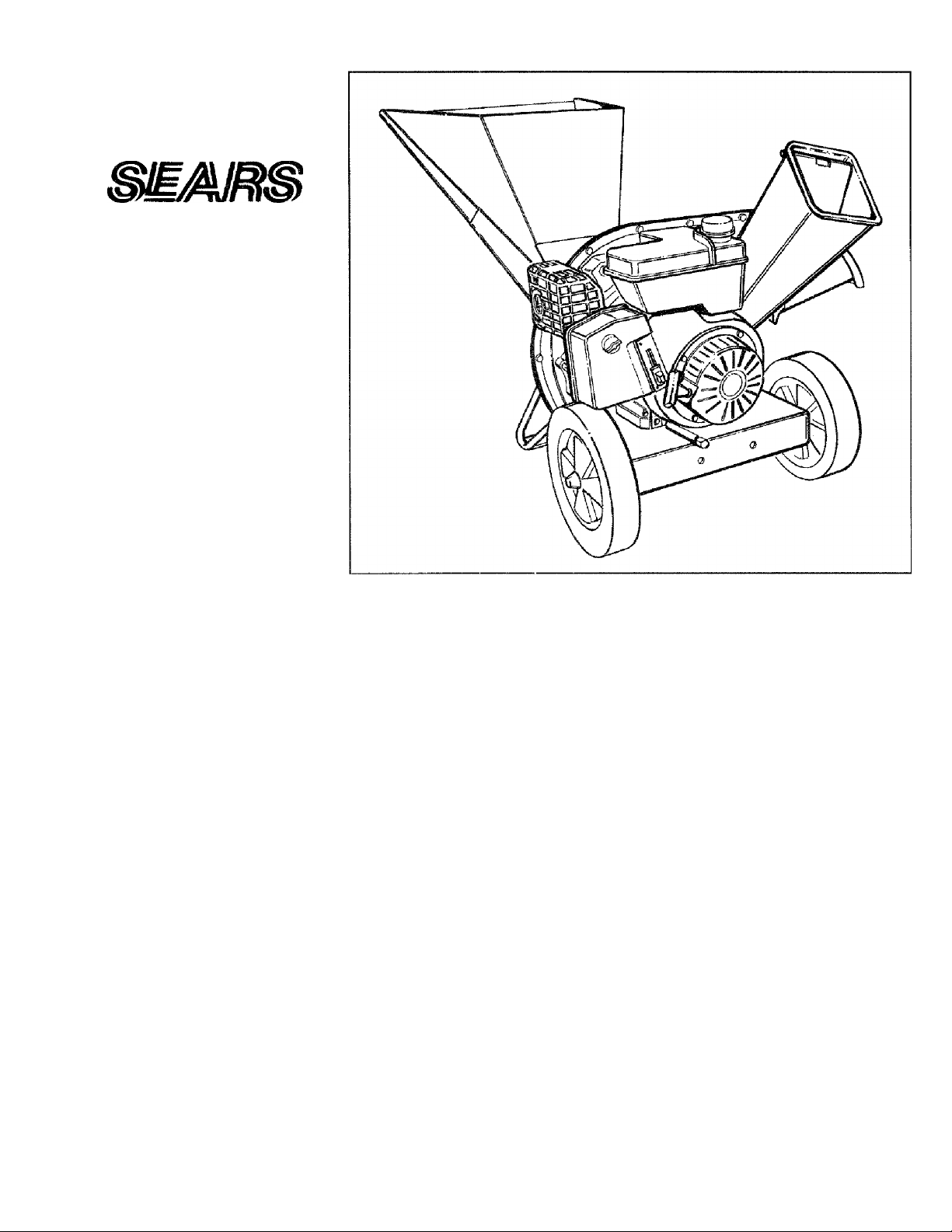
CRAFTSMAN
5 HORSEPOWER
3 CUTTING STAGE
Caution:
Read and Follow
All Safety Rules
and instructions
Before Operating
This Equipment
SEARS, ROEBUCK AND CO., Hoffman Estates, IL 60179 U.S.A.
fVlULCHING AND BAGGING
CHIPPER-SHREDDER
Assembly
Operation
Customer Responsibilities
Service and Adjustment
Repair Parts
tinted in U.S.A.
770-8901L 8/95
Page 2

IMPORTANT
THIS SYMBOL POIMTS OUT IMPORTANT SAFETY INSTRUCTIONS WHICH, IF NOT FOLLOWED, COULD ENDANGER THE PERSON
AL SAFETY AND/OR PROPERTY OF YOURSELF AND OTHERS. READ AND FOLLOW ALL INSTRUCTIONS IN THIS MANUAL
A
A
BEFORE ATTEMPTING TO OPERATE YOUR CHIPPER-SHREDDER. FAILURE TO COMPLY WITH THESE INSTRUCTIONS MAY
RESULT IN PERSONAL INJURY. WHEN YOU SEE THIS SYMBOL; ^ HEED ITS WARNING.
Your chipper-shredder was built to be operated according to the rules for safe operation in this manual.
DANGER:
As with any type of power equipment, carelessness or error on the part of the operator can result in
serious injury. This chipper-shredder is capable of amputating lingers and hands and throwing objects.
Failure to observe the following safety instructions could result in serious injury or death.
SAFE OPERATION PRACTICES
. I. GENERAL OPERATION
llr 1. Read this owner’s guide carefully in its entirety before attempt
ing to assemble this machine. Read, understand, and follow all
instructions on the machine and in the manual(s) before opera
tion. Be completely familiar with the controls and the proper
use of the machine before operating it. Keep this manual in a
safe place for future and regular reference and for ordering
replacement parts.
2. Your chipper-shredder is a powerful tool, not a plaything.
Therefore, exercise extreme caution at all times. Your unit has
been designed to perform two jobs; to chip and shred vegeta
tion found in a normal yard. Do not use it for any other pur
pose.
3. Never allow children under age 16 to operate the unit. Children
16 years and older should only operate the unit under close
parental supervision. Only responsible individuals who are
familiar with these rules of safe operation should be allowed to
use your unit.
4. Keep the area of operation clear of all persons, particularly
small children and pets. Stop the engine when they are in the
vicinity of the unit. Keep work area clean and clear of branches
or obstacies which could cause you to stumble or fall,
5. When feeding material into this equipment, be extremely care
ful that pieces of metal, rocks, bottles, cans or other foreign
objects are not included. Personal injury or damage to the
machine could result.
6. Always wear safety glasses or safety goggles, during operation
and while performing an adjustment or repair, to protect eyes
from foreign objects that may be throv^n from the machine.
7. Wear sturdy, rough-soled work shoes and close fitting slacks
and shirt. Shirt and slacks that cover the arms and legs and
steel-toed shoes are recommended. Do not wear loose fitting
clothes or Jewelry and secure hair so it is above shoulder
length. They can be caught in moving parts. Never operate a
unit in bare feet, sandals or sneakers. Wear gloves when feed
ing material in the chipper chute or shredder hopper,
8. Never place your hands, feet, or any part of your body into the
shredder hopper, chipper chute, discharge opening, or near
any moving part while the engine is running. Keep clear of the
discharge opening at all times. If it becomes necessary to
push material into the chipper chute or shredder hopper, use a
small diameter stick, NOT YOUR HANDS.
9. If it is necessary for any reason to unclog the feed intake or
discharge openings or to inspect or repair any part of the
machine where a moving part can come in contact with your
body or clothing, stop the machine, allow it to cool, disconnect
the spark plug wire from the spark plug and move it avi?ay from
the spark plug before attempting to unclog, inspect or repair,
10, Do not operate unit while under the influence of alcohol or
drugs.
11. The machine should only be operated on a level surface. Never
operate your unit on a slippery, wet, muddy or icy surface.
Keep your work area clean and clear of branches or obstacles
which could cause you to stumble and fall. Do not overreach,
Maintaining proper footing and balance is essential to prevent
ing accidents.
12. Do not allow an accumulation of processed material to build
up in the discharge area as this will prevent proper discharge
and can result in kick-back from the chipper chute.
13. Keep your face and body back from chipper chute to avoid
accidental bounce back of any material.
14. Do not transport machine while engine is running.
15. If the cutting mechanism strikes a foreign object or if your
machine should start making an unusual noise or vibration,
immediately stop the engine and allow the machine to come to
a complete stop. Disconnect the spark plug wire and move it
away from the spark plug, Take the following steps.
• Inspect for damage.
• Repair or replace any damaged parts.
• Check for any loose parts and tighten to assure continued
safe operation.
16. Never attempt to attach or remove catcher bag when engine is
running. Shut the engine off and wait for the impeller to come
to a complete stop. The impeller continues to rotate for a few
seconds after the engine is shut off. Never place any part of
the body in the impeller area until you are sure the impeller has
stopped rotating.
17. Muffler and engine become hot and can cause a burn. Do not
touch,
18. Do not allow leaves or other debris to build-up on engine’s
muffler. The debris could ignite and cause a fire.
19. Do not attempt to shred or chip material larger than specified
in this manual. Personal injury or damage to the machine
could result.
20. Do not operate engine if air cleaner or cover over carburetor
air-intake is removed, except for adjustment. Removal of such
parts could create a fire hazard.
21. Only use accessories approved for this machine by the manu
facturer. Read, understand, and follow all Instructions provid
ed with the approved accessory.
22. If situations occur which are not covered by this manual, use
care and good judgment. Contact your dealer for assistance.
23. Keep discharge chute deflector, chipper chute door, and all
other guards and safety devices in place and operating proper
ly.
24. Only operate unit in good daylight. Do not operate unit at night
or in dark areas where your vision may be impaired.
II. CHILDREN
^Tragic accidents can occur if the operator is not alert to the pres
ence of small children. Children are often attracted to the chipper
shredder and the chipping and shredding activity. Never assume
that children will remain where you last saw them.
1. Keep children out of the work area and under the watchful eye
of a responsible adult other than the operator.
2. Be alert and turn the unit off if a child enters the area.
3. Never allow children under the age of 16 to operate the chip
per-shredder.
Page 3
III. SERVICE
k 1, Use extreme care in handling gasoline and other fuels. They
are extremely flammabie and the vapors are explosive.
a. Store fuel and oil in approved containers, away from heat
and open flame, and out of the reach of children. Check
and add fuel before starting the engine. Never remove gas
cap or add fuel while the engine is running. Allow engine
to cool at least two minutes before refueling.
b. Replace gasoline cap securely and wipe off any spilled
gasoline before starting the engine as it may cause a fire
or explosion.
c. Extinguish all cigarettes, cigars, pipes and other sources
of ignition.
d. Never refuel unit indoors because flammable vapors will
accumulate in the area.
e. Never store the machine or fuel container inside where
there is an open flame or spark such as a gas hot water
heater, space heater, clothes dryer or furnace.
2. Never run your machine in an enclosed area as the exhaust
from the engine contains carbon monoxide, which is an odor
less, tasteless and deadly poisonous gas.
3. To reduce fire hazard, keep engine and muffler free of leaves,
grass, and other debris build-up. Clean up fuel and oil spillage.
Allow unit to cool at least 5 minutes before storing.
4. Before cleaning, repairing, or inspecting, make certain the
impeller and ali moving parts have stopped. Disconnect the
spark plug wire and keep wire away from spark plug to prevent
accidental starting, Do not use flammable solutions to clean
air filter.
5. Check the blade and engine mounting screws at frequent inter
vals for proper tightness. Also visually inspect blades for wear
and/or damage (e.g., bent, cracked). Replace with biades
which meet original equipment specifications.
6. Keep all nuts, bolts, and screws tight to be sure the equipment
is in safe working condition.
7. Never tamper v;ith safety devices. Check their proper opera
tion regularly.
8. After striking a foreign object, Immediately stop the engine,
disconnect the spark plug wire from the spark plug, and thor
oughly inspect the unit for any damage. Repair damage before
starting and operating unit.
9. Do not alter or tamper vdth the engine’s governor setting. The
governor controls the maximum safe operating speed of the
engine. Over-speeding the engine is dangerous and will cause
damage to the engine and to other moving parts of the
machine.
OWNER’S
MANUAL
SAFETY LABEL
WARNING — YOUR RESPONsmiuTY
A
Restrict the use of this power machine to persons who read,
understand and follow the warnings and instructions in this
manual and on the machine.
Page 4

CONGRATULATIONS on your purchase of a Sears
Craftsman Chipper-Shredder. If has been designed, engi
neered and manufactured to give you the best possible
dependability and performance.
Should you experience any problem you cannot easily
remedy, please contact your nearest Sears Service Center/
Department in the United States. We have competent, welltrained technicians and the proper tools to service or repair
this unit.
Please read and retain this manual. The instructions will
enable you to assemble and maintain your chipper-shredder
properly. Always observe the “SAFETY RULES.”
MODEL
NUMBER 247.795850
SERIAL
NUMBER
DATE OF
PURCHASE.
THE MODEL AND SERIAL NUMBERS WILL BE FOUND
ON A LABEL ATTACHED TO THE FRAME OF THE
CHIPPER-SHREDDER.
YOU SHOULD RECORD BOTH SERIAL NUMBER AND
DATE OF PURCHASE AND KEEP IN A SAFE PLACE
FOR FUTURE REFERENCE.
CUSTOMER RESPONSIBILITIES
Read and observe the safety rules.
Follow a regular schedule in maintaining, caring for
and using your chipper-shredder.
Follow the instructions under “Customer Respons
ibilities” and “Storage” sections of this Owner’s
Manual.
PRODUCT SPECIFICATIONS
Horsepower;
Engine Oil: SAE 30
API Classification SF, SG or SH (21 ounces)
Fuel Capacity:
(Unleaded)
Spark Plug (Gap .030 in.): Champion N4C
(or Equivalent)
5.0
3 Quarts
MAINTENANCE AGREEMENT
A Sears Maintenance Agreement is available on this
product. Contact your nearest Sears store for details.
WARNING: This unit is equipped with an internal combus
tion engine and should not be used on or near any unim
proved forest-covered, brush-covered or grass-covered land
unless the engine’s exhaust system is equipped with a
spark arrester meeting applicable local or state laws (if any).
If a spark arrester Is used, it should be maintained in effec
tive working order by the operator.
In the State of California the above is required by law
(Section 4442 of the California Public Resources Code).
Other states may have similar laws. Federal laws apply on
federal lands. A spark arrester for the muffler is available
through your nearest Sears Authorized Service Center (See
the REPAIR PARTS section of this manual.)
WARRANTY
FULL ONE YEAR WARRANTY ON CRAFTSMAN GAS CHIPPER-SHREDDER
For one year from the date of purchase, when this Craftsman chipper-shredder is maintained, lubricated, and
tuned up according to the operating and maintenance instructions in the operator’s manual, Sears will repair,
free of charge, any defect in material or workmanship.
This warranty excludes the blades, chipper blades, flails, air cleaners, spark plugs, catcher bags and tires,
which are expendable parts and become worn during normal use.
If this chipper-shredder is used for commercial or rental purposes, this warranty applies for only 30 days from
the date of purchase.
WARRANTY SERVICE IS AVAILABLE BY CONTACTING THE NEAREST SEARS SERVICE CENTER IN THE
UNITED STATES. THIS WARRANTY APPLIES ONLY WHILE THIS PRODUCT IS IN USE IN THE UNITED
STATES.
This warranty gives you specific legal rights, and you may also have other rights which vary from state to state.
SEARS ROEBUCK AND CO., DEPT. 817WA. HOFFMAN ESTATES. IL 60179
Page 5

TABLE OF CONTENTS
SAFETY RULES............................................................................2
PRODUCT SPECIFICATIONS
WARRANTY...................................................................................4
INDEX.......................................................................................... 5
ACCESSORIES.............................................................................5
ASSEMBLY.................................................................................6-8
OPERATION............................................................................8-11
....................................................
INDEX
.
Accessories...............................
Adjustments:
Carburetor
Engine Speed
Throttle..................................
Assembly Instructions:
Catcher Bag
Chute Deflector
Hopper Assembly
Catcher Bag
Catcher Bag
Controls
Customer Responsibilities
Engine:
Maintenance
Starting
Stopping
Storage.................................
Fuel............................................
Lubrication
............................
......................
.........................
...................
................
.........................
..............................
.....................................
........................
.................................
...............................
................................
C
E
F
L
...............................
.............................
.............................
.............................
................................
................................
................................
...........................7, 8
...........................7, 8
................................8
.................4, 12, 13
......................
..............................
.........................
..........................
..............................
..............................
12, 13
.....9
...14
16
16
16
11
10
12
CUSTOMER RESPONSIBILITIES......................................12, 13
4
5
7
7
7
STORAGE....................................................................................14
SERVICE AND ADJUSTMENT............................................14-16
TROUBLE SHOOTING
PARTS ORDERING/SERVICE..................................................17
REPAIR PARTS—CHIPPER-SHREDDER........................18, 19
REPAIR PARTS—ENGINE..................................................20-24
Maintenance:
Agreement
Schedule
Engine
Chipper-Shredder ...
Oil..........................................
Operating Tips
Primer...................................
Repair/Replacement Parts
Responsibilities, Customer.....
Safety Rules.........................
Sharpening...........................
Service Recommendations
Spark Plug............................
Specifications.......................
Storage
Table of Contents
Trouble Shooting
Unclogging
Unpacking
Warranty ..............................
.....................
.........................
.............................
.....................
.................................
...........................
............................
..............................................................17
M
...............................4
........................
.
....................
............................
0
............................
...............................9
P
............................
R
.............................
.......................
S
............................
T
................
.................
u
w
.....................18-24
.................4, 12-14
..............................
....................
............................
.............................
...............................4
.............................
...............................
.............................
.....................
...............................
...............................
...12
12, 13
15, 16
14, 15
12
10
11
2
12
13
14
5
17
6
4
ACCESSORIES
These accessories were available when the chipper-shredder was purchased. They are also available at most
Sears retail outlets, catalog and service centers. Most Sears stores can order repair parts for you, when you pro
vide the model number of your chipper-shredder.
ENGINE CHIPPER-SHREDDER
Spark
Plug
Air
Filter
Muffler Engine
Oil
Gas Can
Stabilizer
i
Page 6
ASSEMBLY INSTRUCTIONS
Flat-H
Washer
5/16 " I.D.
- Hex Lock
Nut 5/16-18
Hex Bolt
5/16-18 X 8-3/8" Long
Thread
IMPORTANT: This unit is shipped WITHOUT GASO
LINE or OIL in the engine. After assembly, see opera
tion section of this manual for proper fuel and engine
oil recommendations.
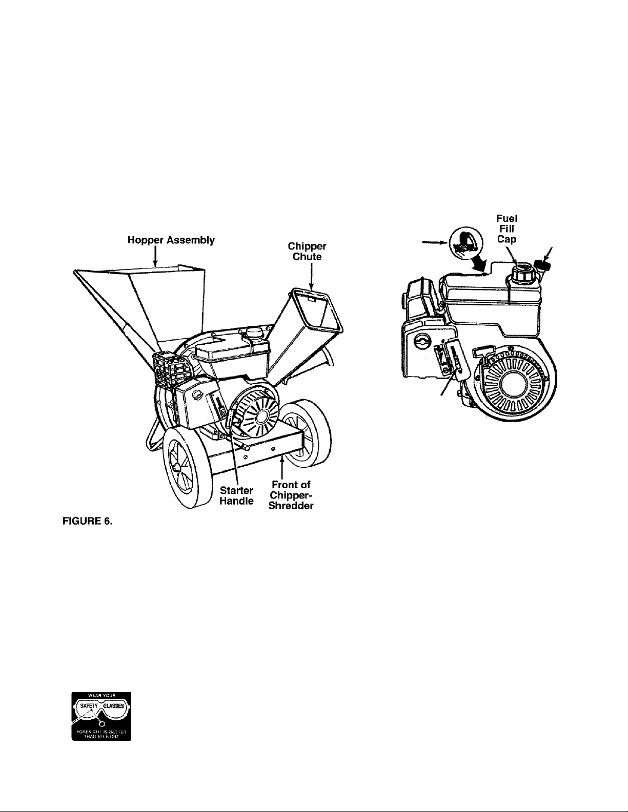
NOTE: To determine right and left hand sides of your
chipper-shredder, stand behind the unit with the
engine the farthest away from you. See figure 6.
Your chipper-shredder has been completely assem
bled at the factory, except for the hopper assembly
(hopper hood and upper leaf ramp section have been
sub-assembled), upper guide assembly, chute
deflector and the catcher bag. The hardware pack
safety glasses and a bottle of oil are also included in
the carton.
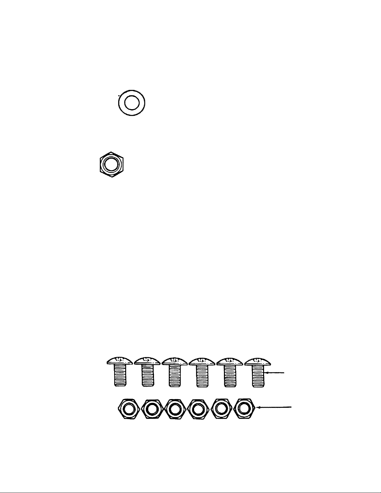
The hardware pack contains the parts shown in figure
1 (shown full size).
TO REMOVE CHIPPER-SHREDDER FROM CARTON
Cut the corners of the carton. Remove all packing
inserts. Roll chipper-shredder out of the carton. Make
certain all parts and literature have been removed
before the carton is discarded.
TOOLS REQUIRED FOR ASSEMBLY
(1) Phillips Screwdriver
(2) 1/2" or Adjustable Wrenches
(2) 7/16" or Adjustable Wrenches
(1) Funnel
Truss Machine Screws
1/4-20 X 1/2" Long
Hex Lock Nuts
1/4-20 Thread
FIGURE 1.
Page 7
Spacers
(Inside
Ujinge)
Hand
Knob
FIGURE 2
Hopper
I tawH ti*R
Releasi
Bar
FIGURE 4.
FIGURE 5.
Release Assembly
Hex Bolt
8-3/8" Long
Inlet
^3 Uide
Flat Washer
Hex Lock Nut
Hopper Pivot Hopper Assembly
Door /V t~
Truss Screws
and Nuts
Upper Screw and Nut
Guide (Assemble
Assembly ' pj^st)
Housing
Assembly
Hex Bolt
Chute
Deflector
\
Upper
Guide
Upper
Leaf Ramp
Section
Remove Truss
HOW TO SET-UP YOUR CHIPPER-SHREDDER
MAKE CERTAIN THE SPARK PLUG
WIRE IS DISCONNECTED AND MOVED
A
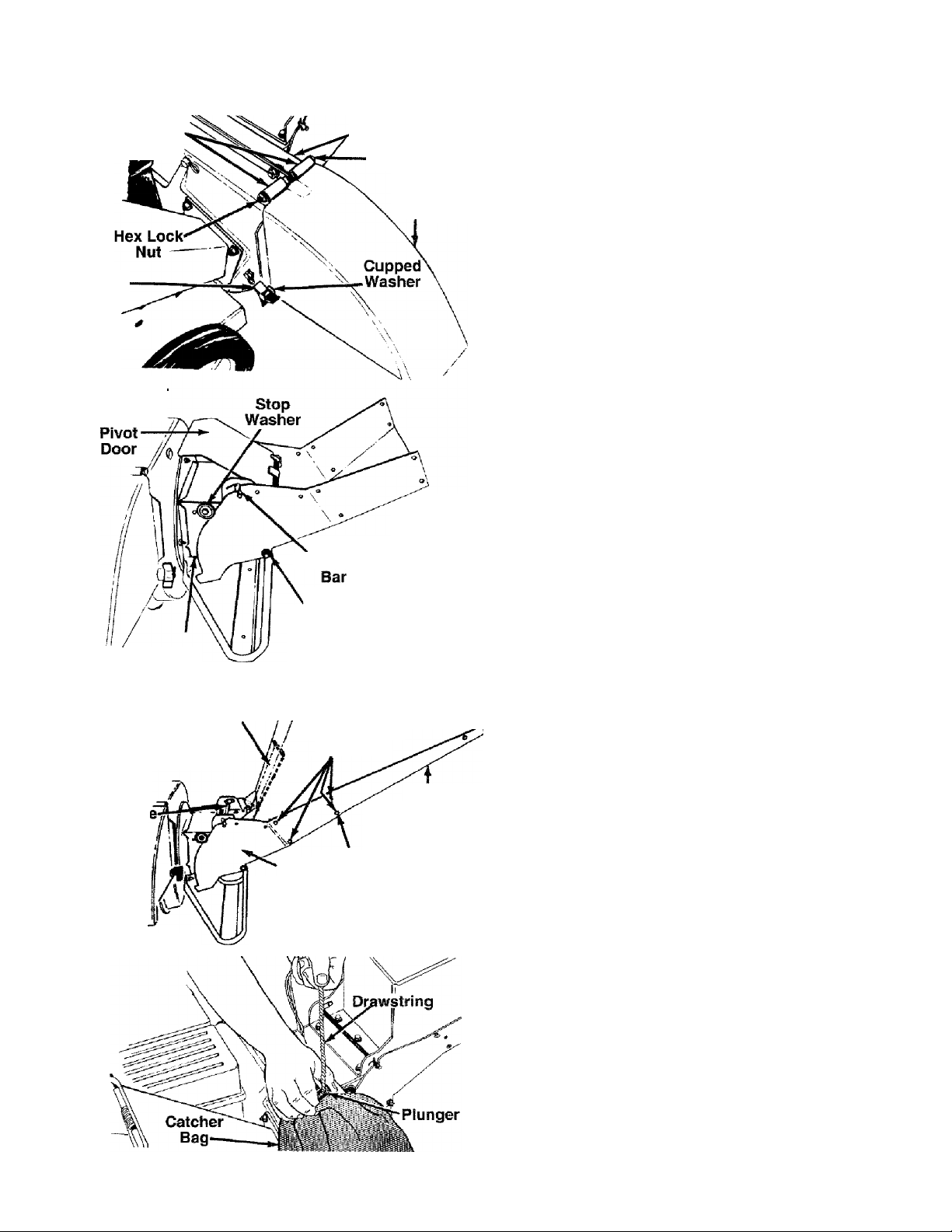
-ATTACHING THE CHUTE DEFLECTOR
• Remove the hand knobs and cupped washers from
each side of the discharge opening on the left side
of the chipper-shredder.
• Remove hex lock nut, two spacers and hex bolt
using two 7/16" wrenches from inside the hinge on
top of the housing assembly. Do not remove one
spacer from the hex bolt.
• Place the chute deflector in position on the dis
charge opening. Insert hex bolt and spacer through
hinge on chute deflector and housing (spacer fits
inside of hinge). See figure 2.
• Place second spacer over hex bolt, inside other
part of hinge. Secure with hex lock nut. Tighten
securely.
• Secure both sides of chute deflector to housing
using hand knobs and cupped washers (cupped side
of washers go against chute deflector),
-ATTACHING THE UPPER GUIDE ASSEMBLY
Grasp the upper guide assembiy from the sides and
squeeze in and slide it over the inlet guide so the
edges are under the stop washers. Adjust so the
holes in the upper guide assembly are aligned with
the holes in the inlet guide. Insert the hex toll 8-3/8"
long through the upper guide assembly and the inlet
guide. Secure with flat washer and lock nut.
NOTE: Make certain the upper guide assembly can
pivot by lifting it up until it locks in the raised position.
If it does not pivot freely, loosen the hex lock nut a
turn or two and test.
-ATTACHING THE HOPPER ASSEMBLY
Your chipper-shredder has been shipped with the
upper leaf ramp section attached to the hopper
assembly. See figure 4. Attach the hopper assembly
to the upper guide assembly as follows. Be certain to
place heads of all truss machine screws inside of
hopper assembly.
• Remove one truss machine screw and nut from
each side of hopper assembly as shown in figure 4.
Push hopper pivot door down inside lower part
of hopper as you place hopper assembiy (both
pieces) inside upper guide assembly. Replace
truss screws and nuts just removed, using the hole
shown in figure 4, one on each side. Tighten finger
tight only.
NOTE: You may have to squeeze in the sides of the
hopper to start the screws. If you have difficulty align
ing the holes, loosen the two screws on the upper end
of the hopper assembly.
• Place the six truss machine screws and nuts found
in hardware pack in the remaining holes of hopper
assembiy, alternating sides of the unit and tighten
ing finger tight only.
• After assembling all eight screws, tighten them
sscuroly
-ATTACHING THE CATCHER BAG
Your chipper-shredder is equipped with a catcher bag
to catch the shredded material.
AWAY FROM THE SPARK PLUG
BEFORE ASSEMBLING THE CHIPPER
SHREDDER. REFER TO FIGURE 13,
PAGE 11.
Page 8
• To attach the bag, place the opening of the bag
over the chute deflector so it completely covers the
chute opening. Depress the plunger on the draw
string, and pull on the drawstring until the bag is
tight around the chute opening. Release plunger to
lock it into position. See figure 5.
OPERATION
KNOW YOUR CHIPPER-SHREDDER
READ THIS OWNER’S MANUAL AND SAFETY RULES BEFORE OPERATING YOUR CHIPPER-SHREDDER.
Compare the illustrations with your chipper-shredder to familiarize yourself with the location of various controls
and adjustments. Save this manual for future reference.
Spark Plug,
Wire and
Boot
Throttie
Control
Oil Fill and
Dipstick
MEETS ANSI SAFETY STANDARDS
Sears chipper-shredders conform to the safety standard B71.6-1982 of the American National Standards Institute.
OPERATING CONTROLS
RELEASE BAR—Used to release the hopper when
raising or lowering. See figure 10.
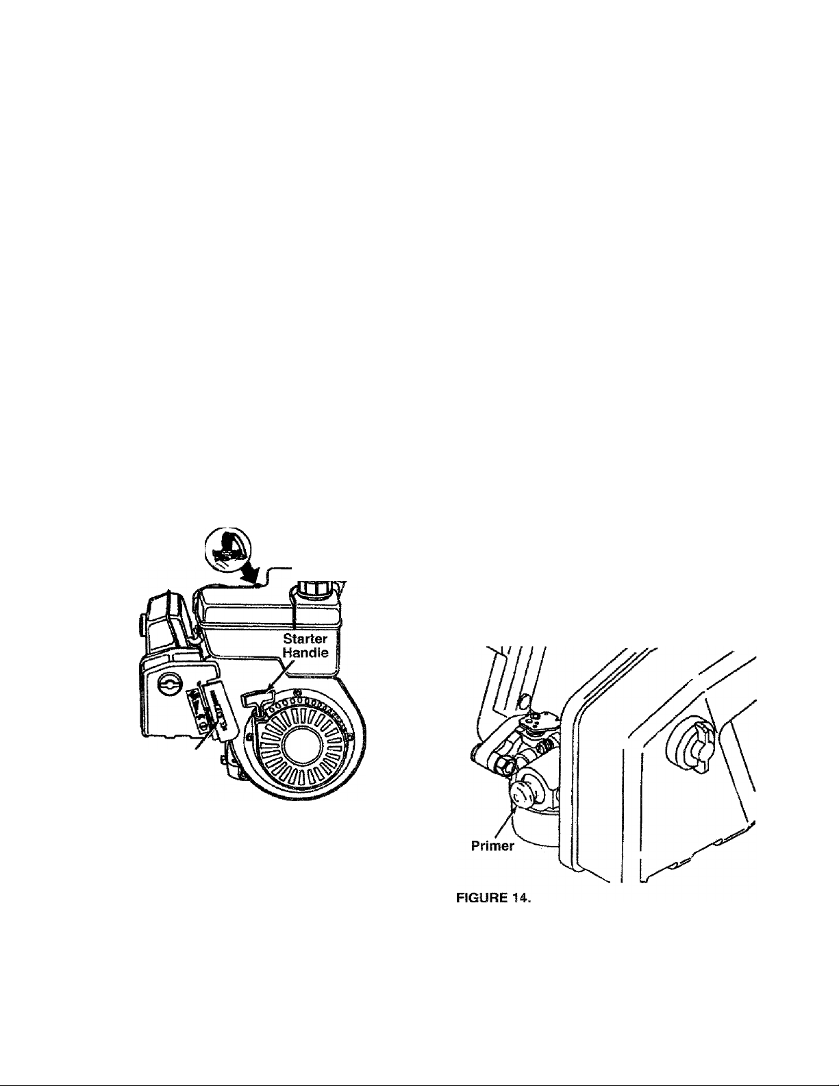
PRIMER—Pumps additional fuel from the carburetor
to the cylinder for use when starting a cold engine.
See figure 14.
BEFORE USING YOUR CHIPPER-SHREDDER, AGAIN REFER TO THE “SAFETY RULES” AS SHOWN ON
PAGE 2 OF THIS MANUAL. ALWAYS BE CAREFUL.
The operation of any chipper-shredder can result in foreign objects being thrown into the eyes, which can
result in severe eye damage. Always wear the safety glasses provided with the chipper-shredder or eye
shields before chipping or shredding, or while performing any adjustments or repairs. We recommend
Wide Vision Safety Mask for over spectacles or standard glasses available at Sears Retail or Catalog
Stores.
STARTER HANDLE—Used to manually start the
engine. See figure 6.
THROTTLE CONTROL—Permits selection of fast or
slow engine speed, and is used to stop the engine.
See figure 6.
Page 9
TO STOP ENGINE
• Move throttle control lever to STOP position. See
figure 6.
• Disconnect spark plug wire and move away from
spark plug to prevent accidental starting while
equipment is unattended. See figure 6.
HOW TO USE YOUR CHIPPER-SHREDDER
Do not attempt to shred or chip any material other
than vegetation found in a normal yard (i.e., branches,
leaves, twigs, etc.).
No Larger Than
1/2" Diameter
(Recommended)
Or 1" Diameter
(Maximum)
Hopper
Assembly
WARNING: THE CHIPPER-SHREDDER
DISCHARGES MATERIALS WITH CON
A
SIDERABLE VELOCITY. KEEP AWAY
FROM THE AREA AROUND THE CHUTE
DEFLECTOR. ALWAYS STOP THE
ENGINE AND DISCONNECT THE SPARK
PLUG WIRE WHEN REMOVING OR
ATTACHING THE BAG WHEN CHANGING
CONTAINERS OR WHEN REMOVING THE
SHREDDED MATERIAL. WEAR SAFETY
GLASSES AND GLOVES WHENEVER
USING YOUR CHIPPER-SHREDDER.
The chipper-shredder is designed for three different
methods of operation.
• Leaves and small branches up to 1/2“ diameter
(recommended) or 1" diameter (maximum) can be
fed into the hopper assembly when it is in the
raised position. See figure 7. If it becomes neces
sary to push material into the chipper-shredder,
use a small diameter stick—NOT YOUR HANDS.
The stick should be small enough that it will be
ground up if gets into the impeller assembly.
FIGURE 7.
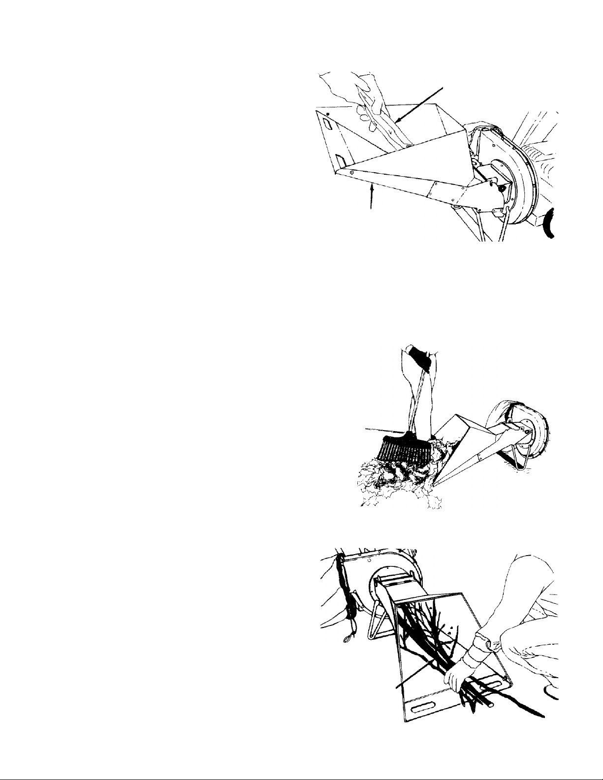
• Leaves and small twigs can be raked into the hop
per assembly when the hopper assembly is low
ered to the ground. See figure 8. Small branches
up to 1/2" diameter (recommended) or 1" diam
eter (maximum) can also be fed into the hopper
assembly in this position. See figure 9.
FIGURE 8.
WARNING: DO NOT PUT MATERIAL
LARGER THAN 1/2" IN DIAMETER (REC
A
OMMENDED) or 1" DIAMETER (MAXI
MUM) INTO THE HOPPER ASSEMBLY.
MATERIAL UP TO A MAXIMUM OF 3" IN
DIAMETER MAY BE FED INTO THE
CHIPPER CHUTE. DO NOT ATTEMPT TO
SHRED OR CHIP ANY MATERIAL LARG
ER THAN 3” IN DIAMETER. PERSONAL
INJURY OR DAMAGE TO THE MACHINE
COULD RESULT.
No Larger Than
1/2" Diameter
(Recommended)'
Or 1" Diameter
(Maximum)
FIGURE 9.
Page 10
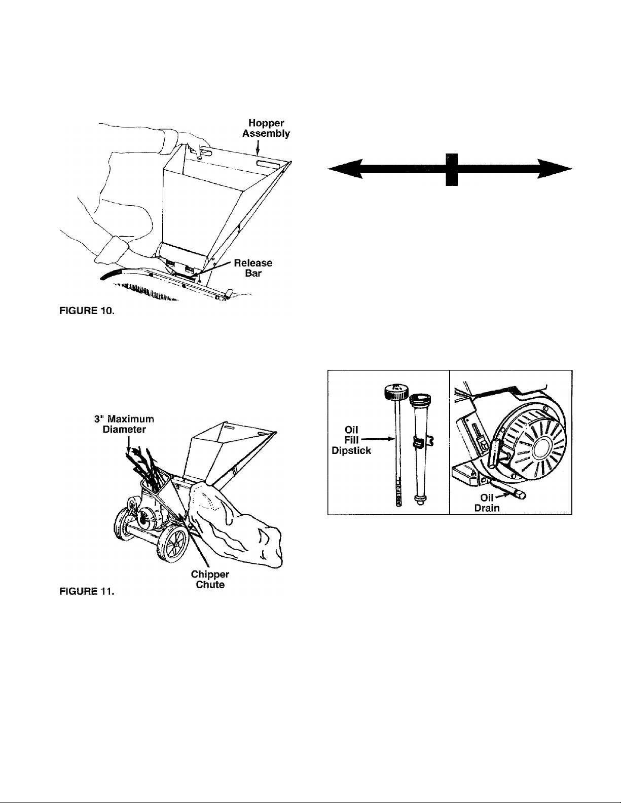
• To lower the hopper assembly, use one hand to
grasp the handle at the top of the hopper assembly
and lift slightly. Pull up on the release bar, and
lower the hopper assembly to the ground. Release
the bar. See figure 10.
GAS AND OIL FILL-UP
OIL (Packed with Unit)
Only use high quality detergent oil rated with API
service classification SF, SG or SFI. Select the oil’s
viscosity grade according to your expected operating
temperature.
Colder ->•- 32“F Warmer
• Bulky material, such as stalks or heavy branches,
up to 3" in diameter, should be fed into the chipper
chute. See figure 11.
WARNING: MAKE CERTAIN THE CHIP
PER CHUTE DOOR IS CLOSED WHEN
A
NOT IN USE.
5W30
NOTE: Although multi-viscosity oils (5W30, 10W30,
etc.) improve starting in cold weather, these multi
viscosity oils will result in increased oil consumption
when used above 32°F. Check your oil level more fre
quently to avoid possible engine damage from run
ning low on oil.
• Fill engine with oil as follows. Remove oil fill dip
stick. See figure 12. With chipper-shredder level,
use a funnel to fill engine with oil to FULL mark on
dipstick. Capacity is approximately 21 ounces. Be
careful not to overfill. Tilt chipper-shredder toward
the left (from behind the hopper), then re-level.
Check oil level. Refill to FULL mark on dipstick if
necessary. Replace dipstick and tighten.
SAE 30
IMPORTANT: There is a flail screen located inside
the housing in the discharge area. If the flail screen
becomes clogged, remove and clean as instructed in
the Service and Adjustments section. For best per
formance, it is important to keep the shredding blade
and the chipper blades sharp. If the composition of
the material being discharged changes (becomes
stringy, etc.) or if the rate at which the material Is dis
charged slows down considerably, it is likely that the
shredding blade and/or chipper blades are dull and
need to be sharpened or replaced. Refer to Service
and Adjustments section.
FIGURE 12.
GAS
• Remove fuel cap and fill fuel tank with about 3
quarts of clean, fresh, lead-free grade automotive
gasoline. DO NOT use Ethyl or high octane gaso
line. Be certain container is clean and free from
rust or foreign particles. Never use gasoline that
may be stale from long periods of storage in the
container. Replace fuel cap.
WARNING: DO NOT FILL CLOSER THAN
1/2 INCH OF TOP OF FUEL TANK TO
A
PREVENT SPILLS AND TO ALLOW FOR
FUEL EXPANSION. IF GASOLINE IS
ACCIDENTLY SPILLED, MOVE CHIPPER
SHREDDER AWAY FROM AREA OF
SPILL. AVOID CREATING ANY SOURCE
OF IGNITION UNTIL GASOLINE VAPORS
HAVE DISAPPEARED.
10
Page 11
Check the fuel level periodically to avoid running out
of gasoline while operating the chipper-shredder, if the
unit runs out of gas as it is shredding or chipping, it
may be necessary to unclog the unit before it can be
restarted. Refer to “Removing the Flail Screen” in
SERVICE AND ADJUSTMENT section.
WARNING: EXPERIENCE INDICATES THAT ALCO
HOL BLENDED FUELS (CALLED GASOHOL OR
USING ETHANOL OR METHANOL) CAN ATTRACT
MOISTURE WHICH LEADS TO SEPARATION AND
FORMATION OF ACIDS DURING STORAGE.
ACIDIC GAS CAN DAMAGE THE FUEL SYSTEM
OF AN ENGINE WHILE IN STORAGE. TO AVOID
ENGINE PROBLEMS, THE FUEL SYSTEM
SHOULD BE EMPTIED OR TREATED WITH FUEL
STABILIZER BEFORE STORAGE FOR 30 DAYS
OR LONGER. USE FRESH FUEL NEXT SEASON.
SEE “STORAGE” SECTION FOR ADDITIONAL
INFORMATION.
NEVER USE ENGINE OR CARBURETOR CLEAN
ER PRODUCTS IN THE FUEL TANK OR PERMA
NENT DAMAGE MAY OCCUR.
Oil Fill and
Spark Plug,
Wire and-
Boot
Fuel Dipstick
Fill Cap
• Attach spark plug wire and rubber boot to spark
plug. See figure 13.
• Place the throttle control lever in FAST position
(UP).
• Push primer two or three times prior to starter oper
ation. See figure 14. Use sharp pushes and wait
about two seconds between each push. In cold
weather (50°F or below), push primer five times.
NOTE: Primer may be needed to restart a warm
engine after a short shut-down.
• Grasp starter handle (see figure 13) and pull rope
out slowly until engine reaches start of compres
sion cycle (rope will pull slightly harder at this
point). Let the rope rewind slowly.
NOTE: A noise will be heard when finding the start of
the compression cycle. This noise is caused by the
flails and fingers which are part of the shredding mech
anism falling into place, and should be expected. In
addition, the flails and fingers will be noisy after the
engine is started, until the impeller reaches full speed.
• Pull rope with a rapid, continuous, full arm stroke.
Keep a firm grip on starter handle. Let rope rewind
slowly. Do not let starter handle snap back against
starter.
NOTE: To prevent the unit from sliding, place your
foot against the tire.
• Repeat preceding two instructions until engine
fires.
NOTE: If engine does not start after three attempts,
push primer two times and pull starter rope again.
Throttle
Control
TO START ENGINE
WARNING: BE SURE NO ONE OTHER
THAN THE OPERATOR IS STANDING
A
NEAR THE CHIPPER-SHREDDER WHILE
STARTING OR OPERATING. DO NOT
OPERATE THIS CHIPPER-SHREDDER
UNLESS THE CHUTE DEFLECTOR HAS
BEEN PROPERLY INSTALLED AND IS
SECURED WITH THE HAND KNOBS.
TO STOP ENGINE
• Move throttle control lever to STOP position (DOWN).
• Disconnect spark plug wire and move away from
spark plug to prevent accidental starting while
equipment is unattended.
11
Page 12
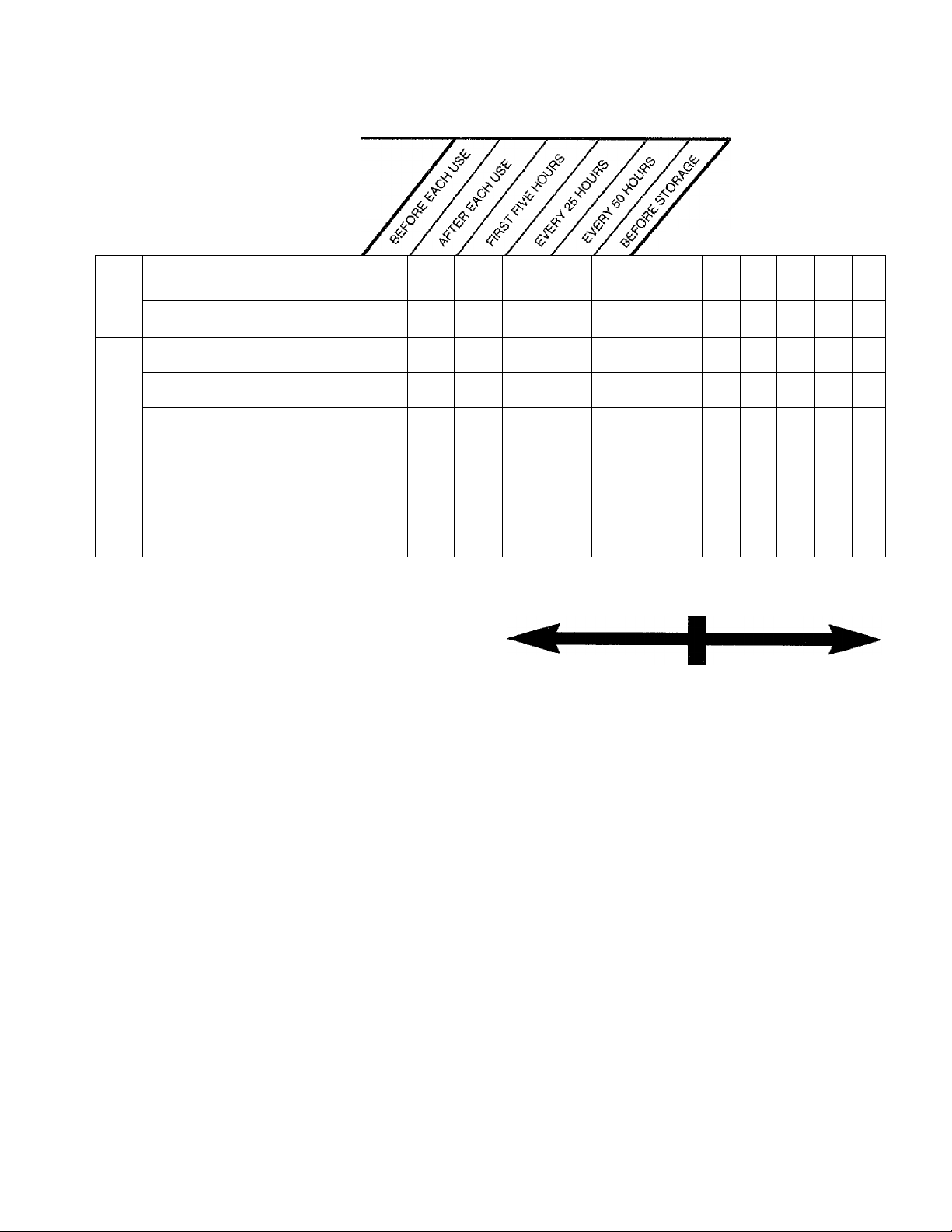
MAINTENANCE SCHEDULE
FILL IN DATES
AS YOU COMPLETE
REGULAR SERVICE
H"
o
Oil Pivot Points
o
o
cr
Clean Shredder
Q.
CUSTOMER RESPONSIBILITIES
SERVICE DATES
V
V
Check Engine Oil
Change Engine Oil
u
Service Air Cleaner
z
o
z
Clean Engine Cylinder
LU
Spark Plug
Muffler
V
V CHECK
GENERAL RECOMMENDATIONS
WARNING: ALWAYS STOP THE ENGINE
AND DISCONNECT THE SPARK PLUG
A.
WIRE BEFORE PERFORMING ANY
MAINTENANCE OR ADJUSTMENTS.
• Periodically check all fasteners and be sure they
are tight.
• Follow the Maintenance Schedule above.
CHIPPER-SHREDDER
LUBRICATION
Lubricate the pivot points on the release bar, hopper
assembly, chute deflector and chipper chute once a
season using a light oil.
CLEANING
• The chipper-shredder may be cleaned by running
water from a hose through the hopper assembly
and chipper chute with the engine running. Allow
the chipper-shredder to dry thoroughly.
• Wash the bag periodically with water. Allow to dry
thoroughly in the shade. Do not use heat.
ENGINE
ENGINE OIL
Only use high quality detergent oil rated with API
service classification SF, SG or SH. Select the oil’s
viscosity grade according to your expected operating
temperature.
V V
V
V
V
Colder
v
5W30
32“F
SAE30
NOTE: Although multi-viscosity oils (SE30, 10W30,
etc.) improve starting in cold weather, these multi- vis
cosity oils will result in increased oil consumption
when used above 32“F. Check your oil level more fre
quently to avoid possible engine damage from run
ning low on oil.
Your four-cycle engine will normally consume some
oil—therefore, check engine oil level regularly approx
imately every five hours of operation and before each
usage. Stop engine and wait several minutes before
checking oil level. With engine level, the oil must be to
FULL mark on dipstick (refer to figure 12). Change
engine oil after the first five hours of operation, and
every twenty-five hours thereafter.
To Drain Oil:
• Drain oil while engine is warm.
a. Remove oil drain plug. Refer to figure 12. Catch
oil in a suitable container.
b. When engine is drained of all oil, replace drain
plug securely.
• Refill with fresh oil. Refer to GAS AND OIL FILL
UP section.
• Replace dipstick.
Warmer
12
Page 13
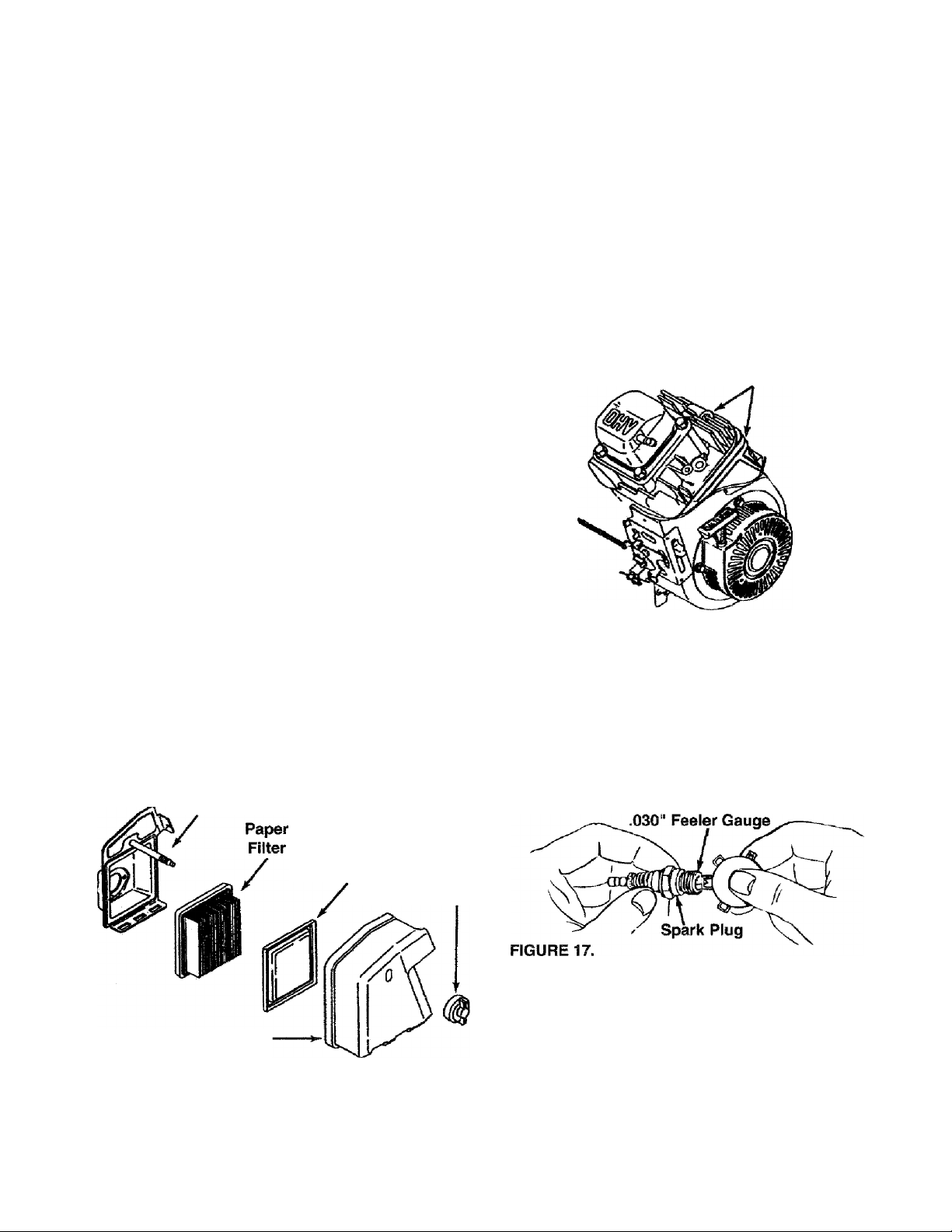
AIR CLEANER
The air cleaner prevents damaging dirt, dust, etc.,
from entering the carburetor and being forced into the
engine and is important to engine life and per
formance.
Never run your engine without air cleaner com
pletely assembled.
To Service Air Cleaner:
Service foam filter after every 25 hours of use, or at
least once a season. Service paper filter every 100
hours of use, or at least once a season. Service foam
filter and paper filter more often under dusty conditions.
• Remove wing nut and cover. Remove paper filter.
See figure 15.
• Remove and inspect filters for discoloration or dirt
accumulation. If necessary, service as follows.
• Foam filter: Clean and re-oil every three months or
every 25 operating hours. Clean and re-oil daily if
used in extremely dusty conditions.
• Wash in water and detergent solution. Squeeze
(don’t twist) until all dirt is removed.
• Rinse thoroughly in clear water.
• Wrap in a clean cloth and squeeze (don’t twist)
until completely dry.
• Saturate with engine oil. Squeeze (don’t twist) to
distribute oil and remove excess oil.
• Paper filter: Replace once a year or every 100
operating hours, or more often if used in extremely
dusty conditions.
• Clean inside of base and cover thoroughly.
• Replace paper and foam filters, making sure the
screen side is toward the paper filter. Replace cover
and wing nut. Tighten securely.
Base
CLEAN ENGINE
Clean engine periodically. Remove dirt and debris
with a cloth or brush. Cleaning with a forceful spray of
water is not recommended as water could contami
nate the fuel system.
Yearly or every 25 hours, whichever occurs first,
remove the blower housing and clean the areas
shown In figure 16 to avoid overspeeding, overheating
and engine damage. Clean more often if necessary.
WARNING: PERIODICALLY CLEAN MUF
FLER AREA TO REMOVE ALL GRASS,
A
FIGURE 16.
SPARK PLUG
The spark plug should be cleaned and the gap reset
to .030" at least once a season or every 50 hours of
operation. See figure 17. Spark plug replacement is
recommended at the start of each season. Refer to
engine parts list for correct spark plug type.
NOTE: Do not sandblast spark plug. Spark plug
should be cleaned by scraping or wire brushing and
washing with a commercial solvent
DIRT AND COMBUSTIBLE DEBRIS.
Cooling Fins
FIGURE 15.
Cover.
Foam Filter Wing
Nut
MUFFLER
Do not operate the chipper-shredder without a muffler
or tamper with the exhaust system. Damaged mufflers
or spark arresters could create a fire hazard. Inspect
periodically, and replace If necessary. If your engine
is equipped with a spark arrester screen assembly,
remove every 50 hours for cleaning and inspection.
Replace if damaged.
13
Page 14

STORAGE
Prepare your chipper-shredder for storage at the end
of the season or if the unit will not be used for 30 days
or more.
WARNING: NEVER STORE MACHINE
WITH FUEL IN THE FUEL TANK INSIDE
A
NOTE: A yearly check-up by your local Sears Service
Center is a good way to make certain your chipper
shredder will provide maximum performance for the
next season.
OF BUILDING WHERE FUMES MAY
REACH AN OPEN FLAME OR SPARK, OR
WHERE IGNITION SOURCES ARE
PRESENT SUCH AS HOT WATER AND
SPACE HEATERS, FURNACES, CLOTHES
DRYERS, STOVES, ELECTRIC MOTORS,
ETC.
CHIPPER-SHREDDER
• Clean the chipper-shredder thoroughly.
• Wipe unit with an oiled rag to prevent rust (use a
light oil or silicone).
ENGINE
IMPORTANT: IT IS IMPORTANT TO PREVENT
GUM DEPOSITS FROM FORMING IN ESSENTIAL
FUEL SYSTEM PARTS SUCH AS CARBURETOR,
FUEL FILTER, FUEL HOSE, OR TANK DURING
STORAGE. ALSO, EXPERIENCE INDICATES THAT
ALCOHOL BLENDED FUELS (CALLED GASOHOL
OR USING ETHANOL OR METHANOL) CAN
ATTRACT MOISTURE WHICH LEADS TO SEPARA
TION AND FORMATION OF ACIDS DURING STOR
AGE. ACIDIC GAS CAN DAMAGE THE FUEL SYS
TEM OF AN ENGINE WHILE IN STORAGE.
• Drain the fuel tank.
• Start the engine and let it run until the fuel lines and
carburetor are empty.
• Never use engine or carburetor cleaner products in
the fuel tank or permanent damage may occur.
• Use fresh fuel next season.
NOTE: Fuel stabilizer is an acceptable alternative in
minimizing the formation of fuel gum deposits during
storage. Add stabilizer to gasoline in fuel tank or stor
age container. Always follow the mix ratio found on
stabilizer container. Run engine at least 10 minutes
after adding stabilizer to allow the stabilizer to reach
the carburetor. Do not drain the gas tank and carbure
tor if using fuel stabilizer.
• Drain all the oil from the crankcase (this should be
done after the engine has been operated and is still
warm) and refill the crankcase with fresh oil.
• If you have drained the fuel tank, protect the inside
of the engine as follows. Remove spark plug, pour
approximately 1/2 ounce (approximately one table
spoon) of engine oil into cylinder and crank slowly
to distribute oil. Replace spark plug.
OTHER
• Do not store gasoline from one season to another.
• Replace your gasoline can if your can starts to rust.
Rust and^r dirt in your gasoline will cause problems.
• Store unit in a clean, dry area. Do not store next to
corrosive materials, such as fertilizer.
NOTE: If storing in an unventilated or metal storage
shed, be certain to rustproof the equipment by coating
with a light oil or silicone.
SERVICE & ADJUSTMENT
WARNING: ALWAYS STOP ENGINE AND
DISCONNECT SPARK PLUG WIRE AND
A
REMOVING THE FLAIL SCREEN
If the discharge area becomes clogged, remove the
flail screen and clean area as follows.
• Stop the engine, make certain the chipper-shredder
has come to a complete stop and disconnect spark
plug wire from the spark plug before unclogging the
chute.
MOVE IT AWAY FROM SPARK PLUG
BEFORE PERFORMING ANY ADJUST
MENTS OR REPAIRS.
Loosen the two hand knobs on each side of the
chute deflector. Lift the chute deflector up, and tie It
out of the way.
Remove two hairpin clips from the clevis pins which
extend through the housing. Remove the clevis
pins. Lift the fiaii screen from inside the housing.
See figure 18.
Clean the screen by scraping or washing with
water. Reinstall the screen.
NOTE: Be certain to reassemble the flail screen with
the curved side down as shown in figure 18.
14
Page 15

Chute Deflector
Hand Knobs
FIGURE 18.
SHARPENING OR REPLACING THE BLADES
CHIPPER BLADES
• Disconnect spark plug wire and move it away from
spark piug.
• Remove the fiail screen as instructed in previous
section.
• Remove the chipper chute by removing three hex
nuts and washers. A 1/2" wrench is required. See
figure 18.
NOTE: When reassembling, the cupped washer goes
on the bottom of the chipper chute with the cupped
side against the chute.
• Rotate the impeller assembly by hand until you
locate one of the chipper blades in the chipper
chute opening. Remove the blade, using a 3/16"
alien wrench on the outside of the blade and 1/2"
wrench on the impeller assembly (inside the hous
ing). See figure 19.
• Remove the other blade in the same manner.
Replace or sharpen blades. If sharpening, make cer
tain to remove an equal amount from each blade.
Reassemble in reverse order.
Make certain blades are reassembled with the sharp
edge facing the direction shown in figure 18 (sharp
edge is assembled toward the slotted opening in the
impeller assembly). Torque bolts and nuts to 250-350
inch pounds.
SHREDDING BLADE
The shredding blade may be removed for sharpening
or replacement as follows.
• Disconnect spark plug wire and move it away from
spark plug.
• Lower the hopper assembly. Block up the housing.
See figure 20.
• Remove the six hex lock nuts and lock washers
from the housing weld bolts using a 1/2" wrench.
Separate the chipper-shredder into two halves.
• Remove the back-up plate.
NOTE: When reassembling, make certain the open
ing on the back-up plate is toward the bottom of the
unit. The back-up plate may be reversed to provide a
new cutting edge.
FIGURE 19.
FIGURE 20.
Loosen the two hand knobs and cupped washers
which secure the chute deflector, and raise the
chute deflector.
Insert a 1/2" or 3/4" diameter pipe through the flail
screen into the impeller to keep it from turning, or
remove the flail screen and insert a piece of wood
(2 X 4) into the chute opening.
Remove the two outside screws on the blade,
using a 3/16" alien wrench and a 1/2" wrench.
Remove the blade by removing the center bolt, lock
washer and flat washer.
Wrench
15
Page 16

NOTE: Use caution when removing the blade to avoid
contacting the weid boits on the housing.
• When sharpening the blade, follow the original
angle of grind as a guide. It is extremely important
that each cutting edge receives an equal amount of
grinding to prevent an unbalanced blade. An unbal
anced blade will cause excessive vibration when
rotating at high speeds and may cause damage to
the unit.
• The blade can be tested for balance by balancing it
on a round shaft screwdriver or nail. Remove metal
from the heavy side until it is balanced evenly. See
figure 21.
CARBURETOR ADJUSTMENT
WARNING: IF ANY ADJUSTMENTS ARE
MADE TO THE ENGINE WHILE THE
A
The carburetor has been pre-set at the factory and
should not require adjustment. However, if your
engine does not operate properly due to suspected
carburetor problems, take your chipper-shredder to
your nearest SEARS Service Center.
ENGINE IS RUNNING (E.G. CARBURE
TOR), KEEP CLEAR OF ALL MOVING
PARTS. BE CAREFUL OF HEATED SUR
FACES AND MUFFLER.
ENGINE SPEED
Your engine speed has been factory set. Do not
attempt to increase engine speed or it may result in
personal injury. If you believe the engine is running
too fast or too slow, take your chipper-shredder to the
nearest SEARS Service Center for repair and adjust
ment.
• When reassembling the blade, tighten to between
550 and 650 inch pounds, or lacking torque
wrench, tighten securely.
FLAILS
The flails, located inside the housing, may be
reversed when they become dull. It is suggested that
this procedure be performed by your nearest Sears
Service Department.
16
Page 17

TROUBLE SHOOTING
PROBLEM
Engine fails to start • Fuel tank empty, or stale fuel.
Loss of power;
operation erratic
Engine overheats
Too much vibration
Unit does not
discharge
Rate of discharge
slows considerably or
composition of
discharged material
changes
POSSIBLE CAUSE(S) CORRECTIVE ACTION
• Spark plug wire disconnected.
• Engine not primed correctly.
• Throttle control not in correct
starting position,
• Faulty spark plug.
• Spark plug wire loose.
• Blocked fuel line or staie fuel.
• Water or dirt in fuel system.
• Carburetor out of adjustment.
• Dirty air cleaner.
• Carburetor not adjusted
properly.
• Engine oil level low.
* Loose parts or damaged
Impeller.
• Discharge chute clogged.
• Foreign object lodged in impeller.
• Shredding blade and/or chipper
blades dull.
• Fill tank with clean, fresh fuel.
• Connect wire to spark plug.
• Follow priming instructions In operation section.
• Move throttle control to FAST position.
• Clean, adjust gap or replace.
• Connect and tighten spark plug wire.
• Clean fuel line; fill tank with clean fresh gasoline.
® Disconnect fuel line at carburetor to drain fuel
tank. Refill with fresh fuel.
• Adjust carburetor or contact your SEARS
Service Center.
• Service air cleaner. See Customer Responsibilities
section of this manual.
* Contact your SEARS Service Center.
• Fill crankcase with proper oil.
• Stop engine immediately and disconnect
spark plug wire. Tighten all bolts and nuts.
Make all necessary repairs. If vibration continues,
have unit serviced by a SEARS Service Center.
• Stop engine immediately and disconnect
spark plug wire. Clean flail screen and inside
of blower housing. See Service/Adjustments
section of this manual,
• Stop engine immediately and disconnect
spark plug wire. Remove lodged object.
• Sharpen or replace shredding and chipper
blades.
NOTE: For repairs beyond the minor adjustments listed above, please contact your nearest SEARS Service Center.
^ HOW TO ORDER REPLACEMENT PARTS
Each chipper-shredder has its own model number.
Each engine has its own model number.
The model number for your chipper-shredder will be
found on a label attached to the frame.
The model number for the engine will be found on the
blower housing of the engine.
All parts listed herein may be ordered through Sears,
Roebuck and Co. Service Centers and most Retail
Stores.
WHEN ORDERING REPAIR PARTS, ALWAYS GIVE
THE FOLLOWING INFORMATION:
‘PRODUCT - “5 H.P. Chipper-Shredder”
‘MODEL NUMBER - 247.795850
‘ENGINE MODEL NO. - 143.955003
‘PART NUMBER
‘PART DESCRIPTION
Your Sears merchandise has added value when you
consider that Sears has service units nationwide
staffed with Sears trained technicians...professional
technicians specifically trained on Sears products,
having the parts, tools and the equipment to insure
that we meet our pledge to you...“we service what we
sell.”
IF YOU NEED
SERVICE OR PARTS:
REPAIR SERVICE
1-800-4-REPAIR
(1-800-473-7247)
ORDERING PARTS
1-800-FON-PART
(1-800-366-7278)
17
Page 18

SEARS CRAFTSMAN 5 H.P. CHIPPER-SHREDDER MODEL NO. 247.795850
R6p8ir Psrts
18
Page 19

SEARS CRAFTSMAN 5 H.P. CHIPPER-SHREDDER MODEL NO. 247.795850
Repair Parts
KEY
NO.
10 715-0249
11
12 681-0030
13
14 710-1054
15
16 736-0119
17 710-0825
18
19 750-0793
20
22 712-0291
23 714-3010
24
25
26
27 712-3010 Hex Nut 5/16-18 Thd. (Gr. 5)
28 73G“0242
29 720-0170 Hand Knob 75 732-0629 Torsion Spring
30
31
32 781 -0489
33 781-0475
34 736-0170
35 712-3010
36
37 710-0157 Hex Bolt 5/16-24 x .75" Lg.
PART
NO.
1 742-0571 Blade
2 710-1254
736-0217 L-Wash. 3/8" I.D. H.D. 40
4
5 736-0247
6 11459B Flail 43
7 711-0564 Flail Spacer
711-0833B Clevis Pin .496" Dia. 45
8
711-0834A Flail Spacer W/.160" Dia. Hole 46 732-0546 Torsion Spring 1.06" Lg.
9
736-0192 FI-Wash. ,531" I.D. x.94" O.D. 48 710-0601 Hex Wash. Hd. Seif-Tap Scr.
781-0490
712-0411
736-0142 FI-Wash. ,281"I.D.x.50" O.D.
711-0835
781-0457 Shredder Screen 58 11461B Upper Leaf Ramp Section
714-0149B
781-0480
747-0744A Chipper Door Rod 76 747-0747 Hopper Door Rod
732-0542 Torsion Spring 1.14“ Lg. 77 781-0492 Hopper—Pivot Door
781-051OA
Hex Patch Bolt 3/8-24 x 39 710-3008 Hex Bolt 5/16-18 X.75" Lg.
2.25" Lg. (Gr. 8) (Gr. 5)
FI-Wash. .406" I.D. X 1.25"
Spring Roll Pin 1.12" Lg. 47 712-0429 Elastic Lock Nut 5/16-18 Thd.
impeller Ass’y- Comp.f
Chipper Blade 49 11480 Stop Washer
Fiat Hd. Scr. 5/16-24 x ,75" Lg. 50
Hex Top L-Nut 5/16-24 (Gr. 5)
L-Wash. 5/16“ I.D.*
Hex Bolt 1/4-20x3.75" Lg.* 53
Chute Hinge Spacer 1.66" Lg. 55
Clevis Pin .5" Dia. x 4.62" Lg. 56 710-0286 Truss Mach. Scr. 1/4-20 x .5"
Hex Ctr. L-Nut 1/4-20 Thd.
Cotter Pin
Internal Cotter Pin 3/8" Dia. 59 726-0214
Chute Deflector Ass’y.
Bell-Wash. .345" I.D. x .88"
Chipper Door 78 781-0493 Hopper Lockout Brkt.
Chipper Chute Assy. 79 726-0106
Spec. L-Wash. 5/16" I.D.
Hex Nut 5/16-18 Thd. (Gr. 5)
Shredder Frame
DESCRIPTION
O.D. Hdn. 42 781-0474A Flail Housing Ass’y.—R.H.
KEY
NO.
38 736-0119 L-Wash. 5/16" I.D.*
41 681-0004
44
51
52 781-0487B
54 781-0494 Pivot-Hopper Hood
57 712-0107
61 750-0786
62 738-0814 Shredder Axle
63 734-1600 Wheel Ass'y. Comp,
—
—
—
PART
NO.
710-0442
735-0639 Spark Plug Boot
143.955003 Engine—Model 143.955003
747-0531A
736-0264
710-0542
16522B
16524B
764-0199A
723-0400
770-8901L Owner’s Manual
Hex Bolt 5/16-18x1.5" Lg.*
Flail Housing Ass’y.—L.H,
Release Bar
FI-Wash. 5/16" I.D.
Hex Bolt 5/16-18x8.38” Lg.
Back-Up Plate
Inlet Guide Ass’y,
Upper Guide Ass’y.
Hex L-Nut 1/4-20 Thd.
Push Cap 5/8" Dia. Rod
Spacer .64" I.D. x .38" Lg.
Cap Speed Nut 1/4" Rod
Bag (Not Shown)
Safety Glasses (Not Shown)
description
5/16-18 x.75" Lg.
Lg.
find. Ref. 1,6, 7, 8, 9, 10, 11, 12, 13, 14
*Common Hardware—May Be Purchased Locally.
NOTE: Specifications subject to change without
notice or obligation.
19
Page 20

SEARS CRAFTSMAN 5 H.P. ENGINE MODEL NO. 143.955003
Ropdir Psrts
@ l6iA r
20
Page 21

SEARS CRAFTSMAN 5 H.R ENGINE MODEL NO. 143.955003
Repair Parts
21
Page 22

SEARS CRAFTSMAN 5 H.P. ENGINE MODEL NO. 143.955003
Repair Parts
KEY
NO.
1 36617 Cylinder (Incl. 2, 20 & 72) 119 36626
2
4
5 30969 Extension Cap
14 28277 Washer 126
15 30589
16 36618
17 29916
18
19 36639
20 32600
25
25A
26
28
30 36619
35 29826
36
37 29216
38
40 35544A
40 35545A
40 35546
41 35541
41 35542
41 35543
42
42 35548A
42 35549
43 20381
45
46
48
49 36611
50 36676
60 36623
64 650833
65 30200
69
70 36625
72 27642
75 27897 Oil Seal
80
81
82 30591 Governor Gear Ass’y. (Incl. 81)
83 36057 Governor Spool
86
89 610961
90
92 650815 Belleville Washer
93
100
101
103
110
PART
NO.
20727
31857 Oil Drain Extension (1/4-18 x
650548 Screw, 8-32 x 5/16"
36621 Air Baffle (Left) 151
36622 Air Baffle (Right) 153 36649
30200 Screw, 10-24x9.16"
30322 Lock Nut, 8-32
29918
29642 Retaining Ring
35547A Ring Set (Std.)
32875A Connecting Rod Ass’y-
3261OA
35616 Valve Lifter
36624 Cylinder Cover Gasket
30574A Governor Shaft
30590A Washer
650488
611205 Flywheel
650816 Flywheel Nut
34443A Solid State ignition
610118 Spark Plug Cover
651007 Screw, Torx T-15, 10-24 x 15/16"
34231 Ground Wire
Dowel Pin
Governor Rod 126 29315C Intake Valve (1/32" O.S.)
Governor Lever (Incl. 151)
Governor Lever Ciamp 130 650912 Screw, 5/16-18 X 1-1/2"
Extension Spring 135 34645 Resistor Spark Plug (N4C)
Oil Seal
Crankshaft
Screw, 10-32x3/4"
Lock Washer 159 35626
Lock Nut, 10-32 160 36630
Piston, Pin & Ring Set (Std.)
Piston, Pin & Ring Set. 173
Piston, Pin & Ring Set. 182 650451
Piston & Pin Ass’y. (Std.) (Incl. 43)
Piston & Pin Ass’y. (.010" O.S.)
Piston & Pin Ass’y. (.020" O.S.) 207 36632
Ring SetCOlO" O.S.) 223
Ring Set (.020" O.S.)
Piston Pin Retaining Ring 238 38820
Connecting Rod Bolt 245
on Dipper 250
Camshaft
Blower Housing Extension
Screw, 1/4-20 X 1-3/16"
Screw, 10-24x9/16"
Cylinder Cover (Incl. 75 thru 83)
Oil Drain Plug
Screw, 1/4-20 X 1-1/4"
Flywheel Key
description
4-1/2") 125
(.010" O.S.)
(.020" O.S.)
(Incl. 43)
(Incl. 43)
(Incl. 46 & 49)
KEY
NO.
120 36628
125
130A 650999 Screw, 5/16-18x2-41/64”
150 31672 Valve Spring
154
155
157
158
161 651008
161A 651012 Stud
178
184 26756
185 36631
200
206 620973 Terminal
209 650821 Screw, 10-32x1/2"
215 36638 Control Knob
224
239
240 36633
245A
251
252 650821
260
261
261A 650821
262 651008
275
277 651009
278
279
280
285
287
290 30705
292 26460 Fuel Line Clamp
300 36643
301
305
307
308 36651
309 651011
PART
NO.
36471 Exhaust Valve (Std.) (Incl. 151)
36472 Exhaust Valve (1/32“ O.S.)
29314B
31673 Valve Spring Cap
650913
35624A Rocker Arm
650914
36629
36675
650852 Nut, 1/4-20
36637 Control Bracket (Incl. 206 & 215)
650451 Screw, 1/4-20 x 1"
36581
27272A Air Cleaner Gasket
36046
36634 Air Cleaner Filter
36635
650886
36636
651008
36641
36674
650852
36642 Heat Shield
35985B Starter Cup
36246 Fuel Cap
35554 Oil Fill Tube
35499
D ESCRIPTIO N
Cylinder Head Gasket
Cylinder Head
(Ind. 151)
Intake Valve (Std.) (Incl. 151)
Push Rod Guide
Rocker Arm Stud
Nut, 1/4-28
Push Rod
Rocker Arm Cover Gasket
Rocker Arm Cover
Screw, 1/4-20 x 31/64"
Breather Tube
Screw, 1/4-20 x 1"
Carburetor to Intake Pipe Gasket
Intake Pipe
Throttle Link
Intake Pipe Gasket
Screw, 10-32 X 1/2"
Air Cleaner Body (Incl. 239)
Air Cleaner Filter
Air Cleaner Cover
Wing Nut
Screw, 10-32 X 1/2"
Blower Housing
Screw, 1/4-20 x 31/64"
Screw, 10-32 X 1/2"
Screw, 1/4-20 x 31/64"
Muffler
Screw, Torx T-30, 1/4-20 x 2-9/32"
Spacer
Nut and Lock Washer
—
Rivet (Can be purchased locally)
Fuel Line
Fuel Tank (Incl. 301)
“0” Ring
Fill Tube Clip
Screw. 10-32x5/16"
22
Page 23

SEARS CRAFTSMAN 5 H.P. ENGINE MODEL NO. 143.955003
Repair Parts
KEY
NO.
310
313
325
327
341
342
370A 36261
370B
380
RPM Setting;
High Speed: 3450 to 3750
Low Speed; 2000 to 2300
PART
NO.
36640
34080
29443
35392
36644
651010
33107
640004
DESCRIPTION
Dipstick 390
Spacer
Wire Clip
Starter Plug
Fuel Tank Bracket
Screw, 1/4-20 x 7/8"
Lubrication Decal
Speed Control Decal
Carburetor (incl. 184)
KEY
NO.
590736
400
416
417 650760
PART
NO.
36627
36085
DESCRIPTION
Rewind Starter
Gasket Set (Incl. Items Marked PK
in Notes)
Incl. (1) each of 26756, 27272A,
29673,35626, 36526, 36581,
36624,36626
Spark Arrestor Kit (Incl. 417)
(Optional)
Screw, 8-32 x 3/8"
PARTS LIST FOR RECOIL STARTER
KEY
NO.
. . .
11 590705
12 590535
13 590701
PART
NO.
590736
590599A
1
2 590600
590696
3
4 590601
590697
5
6 590698
7 590699
590700
8
Rewind Starter
Spring Pin (incl. 4)
Washer
Retainer
Washer
Brake Spring
Starter Dog
Dog Spring
Pulley & Rewind Spring Ass’yStarter Housing Ass’y.
Starter Rope (98“ x 9/64" Dia.)
Starter Handle
DESCRIPTION
-11
23
Page 24

SEARS CRAFTSMAN 5 H.P. ENGINE MODEL NO. 143.955003
Repair Parts
PARTS LIST FOR CARBURETOR
KEY
NO.
— 640004
16
17 650417
18
25
27
28 632019 Float
29 631028 Float Bowl “O” Ring
30 631021
31 631022
35 36045
36 640007
37 632547
40 640008
44
47
48 631027
PART
NO.
1
631615
2 631767
4 631184
5
631183 Dust Seal (Throttle)
6 640009 Throttle Shutter
7
650506 Shutter Screw
632164
630766 Tension Spring
631867
631024 Float Shaft
27110 Bowl Nut Washer
630748
DESCRIPTION
Carburetor (Incl. 184 of Engine
Parts List)
Throttle Shaft & Lever Assembly
Throttle Return Spring
Dust Seal Washer
Fuel Fitting
Throttle Crack Screw/ldle Speed
Screw
Float Bowl
Inlet Needle, Seat, and Clip
(Incl. 31)
Spring Clip
Primer Bulb/Retainer Ring
Main Nozzle Tube
“0” Ring, Main Nozzle Tube
High Speed Bowl Nut
Welch Plug, Idle Mixture Well
Welch Plug, Atmospheric Vent
24
Page 25

/lANUAL DEL
PROPIETARIO
NUMERO DE
MODELO
247.795850
CRAFTSMAN
5 CABALLOS DE FUERZA
3 ETAPAS DE CORTE
Precaución:
Lea y observe
todas las reglas
y instrucciones
de seguridad antes
de operar este
equipo
SEARS, ROEBUCK AND CO., Hoffman Estates, IL 60179 U.SA
ireso en U.S.A.
CUBRIDOR DE PAJA Y EMBOLSADOR
PfCADORA-DESMENUZADORA
Armado
Operación
Responsabilidades del Cliente
Servicio y Ajuste
Piezas de Reparación
770-8901L 8/95
Page 26

IMPORTANTE “ REGLAS DE SEGURIDAD
ESTE SIMBOLO INDICA INSTRUCCIONES IMPORTANTES PARA SU SEGURIDAD. DEBEN SEGUIRSE RIGUROSAMENTE PARA
evitar peligros PARA EL OPERADOR Y OTROS. LEA LAS SIGUIENTES INSTRUCCIONES DE ESTE MANUAL ANTES DE INSTA
LAR EL EQUIPO DE ILUMINACION. FALTA DE OBEDECER ESTAS INSTRUCCIONES PUEDE RESULTAR EN DAÑO PERSONAL.
A
CUANDO VEA ESTE SIMBOLO^PRESTE ATENCION A SU ADVERTENCIA.
A
PELIGRO' cualquier máquina, error o falta de cuidado por parte del operador puede resultar en lesiones
Su picadora-desmenuzadora fue diseñado para que se opere según las reglas de este manual. Al igual
A
I. OPERACION
Lea este manual del propietario antes de tratar de ensamblar
esta máquina. Lea, comprenda y siga todas las instrucciones de
la máquina y de! manual antes de la operación. Es necesario
familiarizarse con los controles y el uso correcto de la máquina
antes de ponerla en funcionamiento. Mantenga este manual en
un lugar seguro para poder consultarlo como sea necesario y
para hacer el pedido de repuestos.
• Su picadora-desmenuzadora es una herramienta muy potente,
no un juguete. Por lo tanto, es sumamente importante manejar
lo siempre con mucha precaución. Su unidad ha sido diseñada
para cumplir dos funciones; para picar y triturar vegetación
común de jardines. No la utilice para ninguna otra función.
• No permita que los niños menores de 16 años utilicen la
máquina. Niños mayores de 16 años deben operarla solamente
bajo la supervisión de un adulto. Solamente personas respons
ables que saben estas reglas de seguridad deben usar su
unidad.
• Mantenga el área de operaciones libre de personas, sobretodo
niños pequeños y animales domésticos. Apague el motor cuan
do se encuentren cerca de la unidad. Mantenga el área de traba
jo limpia y libre de ramas u obstáculos que pueden hacer que
usted se tropiece o caiga.
• Al alimentar el material a la máquina, tenga mucho cuidado y
asegúrese de que no vayan incluidos pedazos de metales, rocas,
botellas, latas u otros objetos. Lo contrario puede causar
lesiones ai operario o daños a la máquina.
• Utilice siempre anteojos de seguridad durante la operación y
siempre que efectúe un ajuste o reparación, para proteger los
ojos de objetos que pueden ser arrojados por la máquina
• Use zapatos de suela gruesa y pantalones y camisa ajustados
que cubran por completo el cuerpo. Es recomendable usar
botas o zapatos con puntera de acero. No use ropa suelta ni
alhajas y fije el cabello de manera que quede arriba de los hom
bros ya que se pueden atorar en el aparato. Nunca opere la
máquina descalzo, con sandalias o en tenis. Use guantes al ali
mentar el material al canal del picador o a la tolva del triturador.
• Nunca meta las manos, los pies o cualquier parte del cuerpo en
la tolva del triturador, en el canai del picador, en !a abertura de
descarga o cerca a cualquier pieza en movimiento mientras que
el motor este encendido. Manténgase siempre lejos de la aber
tura de descarga. Si necesita empujar el material en la tolva del
triturador o en el canal del picador, use un palo de diámetro
pequeño, NO SUS MANOS.
• Si por algún motivo necesita desatrancar el bocatoma de
alimentación o las aberturas de descarga, o si necesita inspec
cionar o reparar cualquier parte de la máquina en donde una
pieza en movimiento puede entrar en contacto con el cuerpo o la
ropa, detenga la máquina, permita que se enfríe, desconecte el
cable de bujía de la bujía y aléjelo de ésta antes de tratar de
desatrancar, inspeccionar o reparar la unidad.
• No opere esta unidad bajo la influencia del alcohol o drogas.
_____________
' serias. El picadora-desmenuzadora es capaz de cortar dedos, manos y de arrojar objetos. La falta de
atención a las siguientes inslrucciones tie seguridad puede resultar en lesiones serias o causar la muerte.
• La máquina debe usarse solamente en terreno plano. Nunca
utilice su unidad en una superficie resbalosa, húmeda, lodosa o
congelada. Mantenga su área de trabajo limpia sin ramas u
obstáculos que lo pueden tropezar o hacer caer. No trate de
alcanzar algo desde lejos. Es esencial mantener el equilibrio y
los pies firmes para evitar accidentes.
• No permita que se acumule material procesado en la sección de
descarga porque puede prevenir la descarga adecuada y puede
recular por el canal del picador.
• Mantenga su rostro y cuerpo atrás del canal del picador para
evitar el rebote accidental de cualquier material.
• No transporte la máquina mientras el motor este encendido.
• Si el mecanismo de corte golpea un objeto o si su máquina
empieza a hacer ruidos o vibraciones extrañas, apague inmedi
atamente el motor y permita que la máquina se detenga comple
tamente. Desconecte el cable de bujía y aléjelo de la bujía. Siga
los siguientes pasos:
• Inspeccione para ver si hay daños.
• Repare o reemplace cualquier pieza dañada.
• Revise que no hayan piezas sueltas y si las hay apriételas para
asegurar una operación segura.
• Nunca trate de enganchar o de remover la bolsa de recolección
mientras el motor este encendido. Apague el motor y espere a
que el impulsor pare por completo. El impulsor sigue girando
por unos segundos después de apagar el motor. Nunca coloque
ninguna parte del cuerpo en el área del impulsor hasta que este
seguro de que éste se haya detenido.
« El silenciador y el motor se callentan y pueden causar
quemaduras. No los toque.
• No permita que se acumulen hojas u otros objetos en el
silenciador del motor. Los escombros pueden prenderse y
causar un incendio.
® No trate de picar o triturar material más grande de! especificado
en este manual, de lo contrario el operario puede sufrir lesiones
o la máquina se puede dañar.
• No opere el motor si el depurador de aire o la tapa sobre el toma
de aire del carburador esta quitada, excepto para hacer ajustes.
La remoción de tales piezas puede crear un peligro de incendio.
• Use solamente accesorios aprobados por el fabricante para esta
máquina. Lea, comprenda y siga ¡as Instrucciones
proporcionadas con el accesorio aprobado.
• Si ocurren situaciones que no están mencionadas en este manu
al, tenga mucho cuidado y use su sentido común. Para recibir
asistencia, llame a su distribuidor.
« Mantenga el desviador del canal de descarga, la puerta del canal
de descarga y todos los otros seguros y accesorios de seguridad
en su lugar y en buen funcionamiento.
• Opere la unidad solamente en buena luz del día. No la use
durante la noche o en áreas oscuras donde su visión no es ade
cuada.
Page 27

II. NIÑOS
i
Accidentes trágicos pueden suceder si el operador no está alerto a
la presencia de niños pequeños. Los niños a menudo son atraídos
por el picadora-desmenuzadora y por la actividad que ejecutan.
Nunca suponga que los niños permanecerán en e! mismo sitio
donde Ud. los vio hace poco.
• Mantenga a los niños lejos del área de trabajo y bajo la super
visión de un adulto además del operador de la máquina.
• Este alerta y apague la unidad si algún niño se acerca al área.
• Nunca permita que niños menores de 16 años utilicen el
picadora-desmenuzadora.
IV. MANTENIMIENTO
i
• Tenga mucho cuidado con la gasolina y otros tipos de com
bustibles. Son extremadamente inflamables y los gases son
explosivos.
• Almacene el combustible y el aceite en contenedores adecua
dos, lejos de fuentes de calor y llamas y lejos del alcance de
los niños. Revise y añada el combustible necesario antes de
encender el motor. Nunca quite el tapón del tanque o añada
combustible mientras de que la máquina se encuentra en fun
cionamiento. Permita que enfríe el motor por lo menos por
dos minutos antes de llenar el tanque.
• Vuelva a colocar el tapón del tanque de gasolina y limpie la
gasolina chorreada antes de encender de nuevo el motor ya
que puede causar fuego o una explosión,
• Apague todos los cigarrillos, puros, pipas y otras fuentes de
ignición.
• Nunca llene el tanque bajo techo porque los gases inflam
ables se acumularán en el área.
• Nunca guarde la máquina o el contenedor de combustible
bajo techo donde hayan llamas, chispas, calentadores,
secadora u horno.
Nunca use la máquina en un sitio cerrado ya que el escape del
motor contiene monóxido de carbono, el cual es un gas
venenoso mortal que no tiene olor ni sabor.
Para reducir el peligro de incendio, mantenga el motor y el silen
ciador limpio, sin hojas, zacate y otros tipos de residuos. Limpie
los derrames de combustible y de aceite. Permita que la unidad
enfríe por lo menos por cinco minutos antes de almacenarla.
Antes de limpiar, reparar o inspeccionar la máquina, asegúrese
de que e! impulsor y todas las piezas movibles se hayan
detenido. Desconecte el cable de bujía y muévalo lejos de la
bujía para evitar el arranque accidental, No utilice soluciones
inflamables para limpiar el filtro de aire.
Revise con frecuencia los tornillos de la cuchilla y del motor
para asegurarse de que estén bien apretados. También inspec
cione la cuchilla para asegurarse de que no esté dañada o des
gastada (ex: torcida, rota). Reemplácelas con cuchillas que
cumplan con las especificaciones originales de la unidad.
Mantenga todas las tuercas, pernos y tomillos apretados para
asegurar de que el equipo este en buen estado de funcionamien
to.
Nunca descomponga los aparatos de seguridad. Revise el fun
cionamiento adecuado regularmente.
Si golpea algún objeto con la máquina, apague inmediatamente
e! motor, desconecte el cable de bujía e inspeccione completa
mente la unidad para ver si se ha dañado. Repare el daño antes
de encender y utilizar la unidad.
No cambie ni altere la programación del regulador del motor. El
regulador controla la velocidad máxima de operación segura del
motor. Un aumento de velocidad es peligroso y causará daños
al motor y a otras piezas de la máquina en movimiento.
▲
AQVEñlEUClk — SU RESPONSABILIDAD
Limite el uso de esta unidad a personas que leen, comprenden y siguen las
advertencias e instrucciones de este manual y de la máquina.
Page 28

FELICITACIONES por su compra de una Picadora-
Desmenuzadora Craftsman de Sears. Ha sido diseñada,
planeada y fabricada par proporcionarle la confiabilidad y
rendimiento mejor posible. Si tuviera algún problema que
no se pudiera remediar fácilmente, llame a su Centro/
Departamento de Servicio Sears más cercano en los
Estados Unidos. Tenemos técnicos competentes, bien
entrenados y las herramientas adecuadas para servir o
reparar esta unidad. Por favor lea y guarde este manual.
Las instrucciones le permitirán armar y mantener su picadora-desmenuzadora adecuadamente. Siempre observe las
“REGLAS DE SEGURIDAD"
NUMERO DE
MODELO 247.795850
NUMERO DE
SERIE
FECHA DE
COMPRA
LOS NUMEROS DE MODELO Y SERIE SE HAL
LARAN EN UN ROTULO PEGADO AL MARCO DE
LA PICADORA-DESMENUZADORA
USTED DEBERIA REGISTRAR AMBOS. EL NUMERO
DE SERIE Y LA FECHA DE COMPRA Y GUARDAR EN
UN LUGAR SEGURO PARA REFERENCIA FUTURA.
_____________________________________
RESPONSABILIDADES DEL CLIENTE
• Lea y observe las reglas de seguridad.
• Siga un programa regular en mantener, cuidar y
usar su picadora-desmenuzadora.
• Siga las instrucciones en las secciones de
“Responsabilidades del Cliente” y “Almacena
miento” de este Manual del Propietario.
ESPECIFICACIONES DEL PRODUCTO
Caballos de fuerza:
Aceite: SAE 30
Clasificación SF, SG o SH de AP
Capacidad de combustible:
Bujías (Distancia: .030 pul.): Champion J19LM
ACUERDO DE MANTENIMIENTO
Un Acuerdo de Mantenimiento de Sears está
disponible para este producto. Llame a su tienda más
cercana de Sears para detalles.
ADVERTENCIA; Esta unidad está equipada con un motor
de combustión interna y no debería usarse en o cerca de
cualquier terreno cubierto por bosques no mejorados,
cubierto por matorrales o grama a menos que el sistema de
escape del motor esté equipado con un retenedor de chis
pas que cumpla con las leyes aplicables locales o del
Estado (de haberlas). Si se usa un retenedor de chispas,
debería mantenerse en una condición efectiva de trabajo
por el operador.
El Estado de California lo anterior se requiere por ley
(Sección 4442 del Código de Recursos Públicos de
California). Otros Estados pueden tener leyes similares. Las
leyes federales se aplican en los terrenos federales. Un
retenedor de chispas para el silenciador está disponible a
través de su Centro de Servicio Autorizado de Sears (Vea
ia sección de PIEZAS DE REPARACION de este manual.)
5.0
21 onzas
3 Cuartos
(Sin plomo)
(o equivalente)
GARANTIA
GARANTIA COMPLETA DE UN AÑO PARA LA PICADORA-DESMENUZADORA A GASOLINA CRAFTSMAN
A partir de un año de la fecha de compra, cuando esta Picadora-Desmenuzadora Craftsman sea mantenida,
lubricada y puesta a punto de acuerdo con las instrucciones en el manual del propietario, Sears reparará,
gratis, cualquier defecto en materiales y confección.
Esta garantía no incluye cuchillas, cuchillas trituradoras, desgranadoras, filtro de aire, bujías, bolsas
recolectoras y neumáticos, ya que son artículos descartabies que se desgastan durante uso normal.
Si esta Picadora-Desmenuzadora Craftsman se usa para fines comerciales o de alquiler, esta garantía se
aplica por sólo 30 días desde la fecha de compra.
ESTA DISPONIBLE EL SERVICIO DE GARANTIA CONSULTANDO CON ELCENTRO/DEPARTAMENTO DE
SERVICIO MAS CERCANO DE SEARS EN LOS ESTADOS UNIDOS. ESTA GARANTIA SE APLICA
SOLAMENTE MIENTRAS EL PRODUCTO ESTA EN USO EN LOS ESTADOS UNIDOS.
Esta garantía le proporciona derechos legales específicos, y usted puede tener también otros derechos que
pueden variar de Estado a Estado.
SEARS, ROEBUCK AND CO., D/817WA, Hoffman Estates, IL 60179
Page 29

Arandela
plana ( ( ) \
5/16" de diámetro J
interno \w
Contratuerca
hexagonal
de rosca de
Perno
hexagonal
S/16-18 X 8-3/8"
— de longitud
Tornillos de máquina
de refuerzo
1/4-20 X m"
de largo
5/16-18
TABLA DE MATERIAS
REGLAS DE SEGURIDAD...........................................................2
ESPECIFICACIONES DEL pRODUCTO....................................4
ACUERDO DE MANTENIMIENTO..............................................4
RESPONABILIDADES DEL CLIENTE........................................4
GARANTIA.....................................................................................4
ACCESORIOS...............................................................................5
INSTRUCCIONES DE ARMADO.............................................6, 7
OPERACION............................................................................8-12
RESPONABILIDADES DEL CLIENTE
ALMACENAMIENTO
SERVICIO Y AJUSTE
LOCALIZACION DE FALLAS
COMO ORDENAR PIEZAS DE REPUESTO............................18
...............................................................
.........................................................
....................................................
........................
.......
12-14
.15
16, 17
18
ACCESORIOS
Estos accesorios estaban disponibles cuando la
picadora-desmenuzadora se compró. Están también
disponibles en la mayoría de las tiendas minoristas,
por catálogo y en los centros de servicio de Sears. La
mayoría de las tiendas Sears pueden ordenar esos
artículos para usted si informa el número de modelo
de su picadora-desmenuzadora.
MOTOR
FIGURAI.
Contratuerca hexagonal
de rosca de 1/4-20
Bujía Filtro
de aire
i
Silen
ciador
PICADORA-DESMENUZADORA
Conjunto de Enganche
Aceite
de motor
para Remolque
Lata
de gasolina
Estab
ilizador
Page 30

INSTRUCCIONES DE
ARMADO
¡MPORTANTE: Esta unidad se envía SIN GASOLINA
O ACEITE. Después del armado, vea la sección de
operación de este manual para las recomendaciones
del combustible y aceite del motor adecuados.
NOTA: Para determinar los lados de mano derecha e
izquierda de su picadora-desmenuzadora, colóquese
detrás de la máquina con el motor alejado de usted.
Ver la figura 6.
HERRAMIENTAS REQUERIDAS PARA EL ARMADO
(1) Destornillador Phillips
(2) Llaves de 1/2" o ajustabies
(2) Llaves de 7/16" o ajustabies
(1) Embudo
Separadores
(Bisagra
interioré
Perno hexagonal
Deflector
de la tolva
Contratuerca
hexagonal
Perilla de
mano
FIGURA 2.
Su picadora-desmenuzadora ha sido completamente
armada en la fábrica, excepto por el armado de la tolva
{la capucha de la tolva y la sección superior de la
rampa de hojas han sido subarmadas), conjunto de la
guía superior, deflector de la canaleta y la bolsa colec
tora. Se incluyen también en la caja el paquete de fer
retería, los lentes de seguridad y una botella de aceite.
El paquete de ferretería contiene las partes que se
muestran en la figura 1 (mostradas en tamaño real).
PARA EXTRAER LA PICADORA-
DESMENUZADORA DE LA CAJA
Corte las esquinas de la caja. Extraiga todos las
inserciones de empaque. Ruede la picadora-des
menuzadora fuera de la caja. Asegúrese de que
todas las piezas y literatura se hayan sacado antes
de disponer de la caja.
COMO PREPARAR SU PICADORA-
DESMENUZADORA
ASEGURESE DE QUE EL CABLE DE LA
BUJIA ESTE DESCONECTADO Y ALEJA
A
SUJETANDO EL DEFLECTOR DE LA CANALETA
• Quite las perillas de mano y arandela acopadas de
cada lado de la abertura de descarga en el lado
izquierdo de la picadora-desmenuzadora.
• Quite la contratuerca hexagonal, dos separadores
y perno hexagonal de adentro de la bisagra en la
parte superior de ia abertura de descarga. No
extraiga un separador del perno hexagonal.
• Coloque el deflector de ia canaleta en posición en
la abertura de descarga. Inserte el perno hexago
nal y separador en la bisagra en el deflector y
cubierta de la canaleta (el separador calza dentro
— de la bisagra). Vea la figura 2.
• Coloque el segundo separador sobre el perno
hexagonal, dentro de otra parte de la bisagra.
Asegure con la contratuerca hexagonal. Ajuste
firmemente.
• Asegure ambos lados del deflector de la canaleta a
la cubierta usando las perillas de mano y arandelas
acopadas (el lado acopado de las arandelas está
ubicado contra el deflector de la canaleta).
■SUJETANDO EL CONJUNTO DE GUIA SUPERIOR
Sujete el conjunto de guía superior por los lados, pre
sione un poco y deslícelo sobre ia guía de entrada de
manera que los bordes estén debajo de las arandelas
de tope. Ajuste de manera que los hoyos del conjunto
de guía superior queden alineados con los de ia guía
de entrada. Inserte el perno hexagonal de 8-3/8" de
largo a través del conjunto de la guía superior y la
guía de entrada. Asegure con ia arandela plana y la
contratuerca hexagonal.
NOTA: Asegúrese de que el conjunto de guía superi
or pueda pivotear - levante hasta que quede sujetado
en posición elevada. En caso de que no pueda
pivotear libremente, afloje el perno hexagonal dando
una o dos vueltas.
DO DE LA MISMA ANTES DE ARMAR LA
PICADORA-DESMENUZADORA. VEA LA
FIGURAIS.
Page 31

Puerta pivote de
la tolva
ARME PRIMERO ESTE
TORNILLO DE REFUERZO
YTUERCA
Barra de“’
/\
isenganche
Conjunto
superior
FIGURA 4.
Conjunto
de la tolva
^Tornillos de
retuerzo y
tuercas
Quite el tornillo
de refuerzo y la
de la
guía
±
Sección superior
de la rampa de
tuerca
hojas
SUJETANDO EL CONJUNTO DE LA TOLVA
Su picadora-desmenuzadora ha sido enviada con la
sección superior de ia rampa de hojas sujeta al con-
“junto de la tolva. Vea la figura 4. Sujete el conjunto de
la tolva al conjunto de la guía superior como sigue.
Asegúrese de colocar las cabezas de todos los tornil
los de máquina de refuerzo dentro del conjunto de la
tolva.
• Saque un tornillo de máquina de refuerzo y tuerca
de cada lado del conjunto de la tolva como se
muestra en la figura 4. Empuje hacia abajo la puer
ta pivoteada de ia tolva dentro de la parte inferior
de la tolva a medida que coloca el conjunto de la
tolva (ambas piezas) dentro del conjunto de la guía
superior. Vuelva a colocar los tornillos de refuerzo
y tuercas recién quitados, usando el orificio que se
muestra en la figura 4, uno en cada lado. Ajuste
con los dedos solamente.
NOTA: Es posible que tenga que presionar los lados
de la tolva para poder empezar los tornillos. Si tiene
dificultades alineando el hoyo, afloje los dos tornillos
en la parte superior de la tolva.
• Coloque los seis tornillos de máquina de refuerzo y
tuercas que están en el paquete de ferretería en
los orificios restantes del conjunto de ia tolva, alter
nando lados de la unidad y ajustando con los
dedos solamente.
• Después de colocar todos los ocho tornillos,
ajústelos seguramente.
SUJETANDO LA BOLSA COLECTORA
Su picadora-desmenuzadora está equipada con una
bolsa colectora para colectar el material desmenuza
do.
• Para sujetar la bolsa, coloque la abertura de la
misma sobre el deflector de la canaleta de tal
manera de cubrir completamente la abertura de la
misma. Oprima el vástago sobre la cuerda de
extracción, y tire de la misma hasta que la bolsa
esté ajustada alrededor de la abertura de la
canaleta. Libere el vástago para fijarlo en posición.
’—Vea la figura 5.
Page 32

OPERACION
CONOZCA SU PICADORA-DESMENUZADORA
LEA ESTE MANUAL DEL PROPIETARIO Y LAS REGLAS DE SEGURIDAD ANTES DE OPERAR SU PICADO
RA-DESMENUZADORA Compare las ilustraciones con su picadora-desmenuzadora para familiarizarse con la
ubicación de varios controles y ajustes. Guarde este manual para referencia futura.
Conjunto de
la tolva
Canaleta de la
picadora
Bujía,
cable y funda
Control de!
acelerador
Tanque de
combustible
Varilla para
medir la
profundidad
de llenado
de aceite
Manija del
encendido
Parte delantera
dei picadora-
desmenuzadora
FIGURA 6.
CUMPLE CON LAS NORMAS DE SEGURIDAD ANSI
Las picadoras-desmenuzadoras de Sears están en conformidad con la norma de seguridad B71.6-1982 del
instituto Americano de Normas Nacionales.
COiTROLES DE OPERACION
BAFlñA DE DESENGANCHE - Usada para desengan
char la tolva cuando se baje o sube. Vea !a figura 6.
CEBADOR - Bombea una cantidad de combustible
adicional del carburador hacia el cilindro, para ser
usado cuando se arranca un motor frió. Vea la figura
14.
ANTES DE USAR SU PICADORA-DESMENUZADORA, REFIERASE NUEVAMENTE A LAS “REGLAS DE
SEGURIDAD” INDICADAS EN LA PAGINA 2 DE ESTE MANUAL. SIEMPRE SEA CUIDADOSO.
La operación de cualquier picadora-desmenuzadora puede resultar en que haya objetos
extraños proyectados contra los ojos, lo que puede resultar en daños graves a los ojos.
Siempre use los lentes de seguridad que están provistos con la picadora-desmenuzadora o
protectores de los ojos antes de picar o desmenuzar, o mientras efectuando cualquier ajuste o
reparación. Recomendamos la máscara de seguridad Wide Vision para usar sobre los anteojos
o lentes normales, disponible en las tiendas al por menor o de catálogo de Sears.
MANIJA DEL ENCENDIDO - Usada para encender
manualmente el motor. Vea la figura 6.
ACELERADOR - Permite la regulación de velocidad
dei motor entre rápido y lento, y usado para detener
el motor. Vea las figuras 6 y 13.
8
Page 33

PARA APAGAR EL MOTOR
• Mueva el acelerador a la posición STOP, Vea la
figura 6.
• Desconecte el cable de la bujía y aléjelo de la
misma para evitar un arranque accidental mientras
el equipo no esté atendido. Vea la figura 6.
GOMO USAR SU PiCADORA-
DESMENUZADORA
No trate de picar o desmenuzar cualquier material
diferente de vegetación que se encuentra en
cualquier patio normal (por ej., ramas, hojas, ramitas,
etc.).
ADVERTENCIA: LA PICADORA-DES-
MENUZADORA DESCARGA MATERI
A
ALES A UNA VELOCIDAD CONSIDER
ABLE. MANTENGASE ALEJADO DEL
AREA ALREDEDOR DEL DEFLECTOR
DE LA CANALETA. SIEMPRE APAGUE
EL MOTOR Y DESCONECTE EL CABLE
DE LA BUJIA CUANDO ESTE EN PRO
CESO DE SACAR O SUJETAR LA
BOLSA CUANDO CAMBIE LOS CON
TENEDORES O CUANDO EXTRAIGA EL
MATERIAL DESMENUZADO. USE
LENTES DE SEGURIDAD Y GUANTES
SIEMPRE QUE USE SU PICADORA-DESMENUZADORA.
• Pueden rastrillarse hojas y ramitas pequeñas cuan
do el conjunto de la tolva se baja al nivel del suelo.
Vea la figura 8. Ramas pequeñas de hasta 1/2" de
diámetro (recomendado) o de 1" de diámetro (máx
imo) pueden también alimentarse al conjunto de la
tolva en esta posición. Vea la figura 9.
La picadora-desmenuzadora está diseñada para tres
métodos diferentes de operación.
• Hojas y ramas pequeñas de hasta 1/2“ de diámetro
(recomendado) o 1" de diámetro (máximo) pueden
alimentarse en el conjunto de la tolva cuando está
en la posición elevada. Vea la figura 7. Si fuera
necesario empujar e! material dentro de la
picadora-desmenuzadora use un palo de diámetro
pequeño - NO SUS MANOS. El palo debería ser
suficientemente pequeño para ser molido si
quedara atrapado en el conjunto propulsor.
ADVERTENCIA: NO PONGA MATERIAL
MAS GRANDE QUE 1/2" DE DIAMETRO
A
(RECOMENDADO) O 1" DE DIAMETRO
(MAXIMO) DENTRO DEL CONJUNTO DE
LA TOLVA. PUEDE ALIMENTARSE A LA
CANALETA DE PICADO CON MATERI
ALES DE HASTA UN MAXIMO DE 3" DE
DIAMETRO. NO TRATE DE PICAR O
DESMENUZAR CUALQUIER MATERIAL
MAS GRANDE QUE 3" DE DIAMETRO.
PODRIA RESULTAR EN LESIONES PER
SONALES O DAÑOS A LA MAQUINA.
FIGURA 8.
Más pequeño que
1/2" de diámetro
(Recomendado)
o 1" de diámetro
(Máximo)
FIGURA 9.
Page 34

Para bajar el conjunto de la tolva, use una mano
para asir al manija en la parte superior del conjunto
de la tolva y levántela ligeramente. Tire de al barra
de desenganche, y baje el conjunto de la tolva al
suelo. Suelte la barra. Vea la figura 10.
cual se descarga el material, es posible que la
cuchilla de desmenuzar y/o las cuchillas de picar
estén desafiladas y tengan que ser afiladas o reem
plazadas. Refiérase a la sección de Servicio y Ajuste.
LLENADO DE GAS Y ACEITE
ACEITE (INCLUIDO)
Sólo use aceite detergente de alta calidad clasificado
con la clasificación de servicio SF, SG o SH de API.
Seleccione el grado de viscosidad del aceite de
acuerdo con su temperatura esperada de operación.
Material voluminosos, tal como tallos o ramas
pesadas de hasta 3" de diámetro debería ser alimen
tado a la canaleta de la picadora. Vea la figura 11.
ADVERTENCIA: ASEGURESE DE QUE
LA PUERTA DE LA CANALETA DE LA
A
1^1^5C3^E^5T"E ^1^X13^^ ^3U^V^f^5^3
NO SE USA.
Más frío 32^F
5W30
SAE30
Más caliente
NOTA: A pesar de que los aceites de viscosidad
múltiple (5W30, 10W30, etc) mejoran el arranque en
tiempo frío, los mismos resultarán en un consumo
mayor de aceite cuando se usen a una temperatura
mayor de 32^F. Revise su nivel de aceite más fre
cuentemente para evitar daño posible al motor a
causa de funcionar con un nivel bajo de aceite.
* Llene el motor con aceite como sigue. Extraiga la
varilla para medir la profundidad de llenado de
aceite. Vea la figura 12. Con el nivel de la picadora-desmenuzadora use un embudo para llenar de
aceite el motor hasta la marca FULL (LLENO) en la
varilla. La capacidad es de 21 onzas aproximada
mente. Sea cuidadoso de no sobrellenar. Incline la
picadora-desmenuzadora hacia la izquierda (desde
atrás de la tolva), y coloque nuevamente a nivel.
Revise el nivel de aceite. Llene nuevamente a la
marca FULL (LLENO) de la varilla si fuera
necesario. Vuelva a colocar la varilla y ajuste.
FIGURA 11.
IMPORTANTE: Existe una criba de desgranado ubi
cada dentro de la cubierta en el área de descarga. Si
la criba de desgranado se tapona, sáquela y límpiela
como se instruye en la Sección de Servicio y Ajustes.
Para el mejor rendimiento es importante mantener afi
ladas la cuchilla de desmenuzar y las cuchillas de
picar. Si cambia la composición del material que está
siendo descargado (se convierte en tipo encordado,
etc.) o disminuye considerablemente la velocidad a la
Varilla para
medir la
profundidad-
de llenado
de aceite
FIGURA 12.
10
Page 35

GAS
Quite la tapa de combustible y llene el tanque con
aproximadamente 4 cuartos de gasolina de
automóvil, limpia, fresca, sin plomo, de alto grado.
NO USE Etilo o gasolina de alto octano. Asegúrese
de que el contenedor esté limpio y libre de óxido o
partículas extrañas. Nunca use gasolina que esté
rancia por haberse almacenado por un período
largo en el contenedor. Vuelva a colocar la tapa de
combustible.
ADVERTENCIA: NO LLENE POR ENCIMA
DE 1/2 PULGADA DE DISTANCIA DE LA
A
PARTE SUPERIOR DEL TANQUE DE
COMBUSTIBLE PARA EVITAR DER
RAMES Y PARA PERMITIR LA EXPAN
SION DEL COMBUSTIBLE. SI SE DER
RAMA GASOLINA ACCIDENTALMENTE,
RETIRE LA PICADORA-DESNMENUZADORA DEL LUGAR DEL DERRAME.
EVITE CREAR CUALQUIER FUENTE DE
ENCENDIDO HASTA QUE HAYAN DESA
PARECIDO LOS VAPORES DE LA
GASOLINA.
Revise periódicamente el nivel para evitar
quedarse sin gasolina cuando esté operando la
picadora-desmenuzadora. Si la unidad se queda sin
gas mientras está desmenuzando o picando, puede
ser necesario desatancar la unidad antes de que
pueda encenderse
nuevamente. Refiérase a “Extracción del Tamiz de
Desgranar” EN LA SECCION DE SERVICIO Y
AJUSTE.
ADVERTENCIA: LA EXPERIENCIA INDICA QUE
LOS COMBUSTIBLES MEZCLADOS CON ALCO
HOL (LLAMADO GASOHOL O USANDO ETANOL
O METANOL) PUEDE ATRAER HUMEDAD LO QUE
CONDUCE A LA SEPARACION Y FORMACION DE
ACIDOS DURANTE EL ALMACENAMIENTO. EL
GAS ACIDOGENO PUEDE DAÑAR EL SISTEMA
DE COMBUSTIBLE DE UN MOTOR MIENTRAS
ESTA EN ALMACENAMIENTO. PARA EVITAR
PROBLEMAS DEL MOTOR, EL SISTEMA DE COM
BUSTIBLE DEBE VACIARSE O TRATARSE CON
UN ESTABILIZADOR DE COMBUSTIBLE POR 30
DIAS O MAS ANTES DE ALMACENAR. LA PROXI
MA TEMPORADA USE COMBUSTIBLE FRESCO.
VEA LA SECCION DE “ALMACENAMIENTO”
PARA INFORMACION ADICIONAL.
NUNCA USE PRODUCTOS DE LIMPIEZA DE
MOTOR O CARBURADOR EN EL TANQUE DE
COMBUSTIBLE O PUEDE OCURRIR DAÑO PER
MANENTE.
Bu ja
cable y funda
Control del
acelerador
FIGURA 13.
PARA ENCENDER EL MOTOR
ADVERTENCIA: ASEGURESE DE QUE
NADIE MAS QUE EL OPERADOR ESTE
A
• Si fuera necesario una el cable de la bujía y la
• Mueva el acelerador a la posición RÁPIDO (hacia
• Presione el botón del cebador dos o tres veces
NOTA: Puede ser necesario tener que aplicar el
cebado para volver a encender un motor caliente
después de haberlo apagado por un corto período.
• Tome la manija del encendido (vea la figura 13) y
NOTA: Se escuchará un ruido cuando se encuentre
el comienzo del ciclo de compresión, Este ruido es
causado por las desgranadoras y dedos, que son
parte del mecanismo de desmenuzamiento, que
están colocándose en posición, y debería anticiparse.
Además, las desgranadoras y dedos harán ruido
después que se encienda el motor, hasta que el
impulsor alcance la velocidad máxima.
11
PARADO CERCA DE LA PICADORA-DESMENUZADORA MIENTRAS SE ESTE
ENCENDIENDO U OPERANDO. NO
OPERE ESTA PICADORA-DESMENUZADORA A MENOS QUE EL DEFLECTOR
DE LA CANALETA HAYA SIDO INSTALA
DO ADECUADAMENTE Y ESTE ASEGU
RADO CON LAS PERILLAS DE MANO.
funda de goma a la bujía. Vea la figura 13.
arriba).
antes de la operación de arrancar. Vea la figura 14.
Use una presión firme cada vez, espere un poco
después de cada presión. En tiempo frío, presione
el botón del cebador cinco veces.
tire de la cuerda lentamente hasta que el motor
llegue al comienzo del ciclo de compresión (en
este punto deberá tirarse de la cuerda un poco
más fuerte). Deje que la cuerda se enrolle lenta
mente.
Varilla para
medir
la profundidad
de llenado de
aceite
Page 36

• Tíre de ía cuerda con un movimiento del brazo
rápido, continuo y pleno. Sujete firmemente la
manija de encendido. Permita que la cuerda se
enrolíe lentamente. No permita que la manija de
encendido salte hacia atrás contra eí encendido.
NOTA; Para prevenir que la máquina se deslice,
coloque su pie contra el neumático.
• Repita ias dos instrucciones anteriores hasta que
el motor dispare.
NOTA: Si el motor no dispara después de tres inten
tos, presione el botón del cebador dos veces y tire de
la cuerda otra vez.
PARA APAGAR EL MOTOR
• Posicione el acelerador en STOP. (Hacia abajo)
• Desconecte el cable de ia bujía y aléjelo de la
misma para evitar un arranque accidental mientras
ei equipo no esté atendido.
RESPONSABILIDADES DEL CLIENTE
PROGRAMA DE MANTENIMIENTO
ANOTE LAS FECHAS A
MEDIDA QUE COMPLETA
EL SERVICIO REGULAR
O
h
O
Aceitar los puntos de pivote
a
o
ex:
Limpiar la desmenuzadora
a.
Verificar el aceite del motor
Cambiar ei aceite del motor
cc
Servicio al filtro de aire
o
o
s
Limpiar el cilindro del motor
Bujía
Silenciador
DE SERVICIO
V
V
V
i
V
V
V
V
V REVISAR
12
Page 37

RECOMENDACIONES GENERALES
ADVERTENCIA: SIEMPRE APAGUE EL
MOTOR Y DESCONECTE EL CABLE DE
A
LA BUJIA ANTES DE EFECTUAR
CUALQUIER MANTENIMIENTO O
AJUSTES.
• Revise periódicamente todos los remaches y
asegúrese de que estén bien ajustados.
• Siga el programa de Mantenimiento de arriba.
PICADORA-DESMENUZADORA
LUBRICACION
Lubrique los puntos de pivote de la barra de desen
ganche, conjunto de la tolva, deflector de la canaleta
y canaleta de la picadora una vez por temporada
usando aceite liviano.
LIMPIEZA
• La picadora-desmenuzadora puede limpiarse
haciendo correr agua de una manguera a través
del conjunto de la tolva y canaleta de la picadora
con el motor funcionando. Permita que la picadoradesmenuzadora se seque completamente.
• Lave periódicamente la bolsa con agua. Permita
que se seque completamente a la sombra. No use
calor.
MOTOR
ACEITE DEL MOTOR
Sólo use aceite detergente de alta calidad clasificado
con la clasificación de servicio SF, SG o SH de API.
Seleccione el grado de viscosidad del aceite de
acuerdo con su temperatura esperada de operación.
Más frío
5W30
NOTA: A pesar de que los aceites de viscosidad
múltiple (5W30, 10W30, etc) mejoran el arranque en
tiempo frío, los mismos resultarán en un consumo
mayor de aceite cuando se usen a una temperatura
mayor de 32-F. Revise su nivel de aceite más fre
cuentemente para evitar daño posible al motor a
causa de funcionar con un nivel bajo de aceite.
Su motor de cuatro ciclos consumirá normalmente
algo de aceite-por consiguiente, verifique ei nivel de
aceite regularmente cada cinco horas de operación y
antes de cada uso. Apague el motor y espere varios
32^F -►Más callente
SAE30
minutos antes de revisar el nivel de aceite.Con el
nivel de la picadora-desmenuzadora el aceite debe
llegar hasta la marca FULL (LLENO) en la varilla para
medir la profundidad de llenado de aceite (Refiérase
a la figura 12). Cambie el aceite del motor después
de las primeras cinco horas de operación, y cada
veinticinco horas subsecuentemente.
Para drenar el aceite:
• Drene mientras el motor está caliente.
a. Quite el tapón de drenaje de aceite. Refiérase a
la figura 12. Recoja el aceite en un contenedor
apropiado.
b. Cuando se haya drenado el aceite del motor,
reemplace seguramente el tapón de drenaje.
• Vuelva a llenar con aceite fresco. Refiérase a la
sección de LLENADO DE GAS Y ACEITE.
• Vuelva a colocar !a varilla.
FILTRO DE AIRE
El filtro de aire evita que suciedad, polvo, etc. dañinos
penetren en el carburador y sean forzados dentro del
motor y es importante para la duración y rendimiento
del motor.
Nunca haga funcionar sin el filtro de aire comple
tamente armado.
Para servir el filtro de aire:
De mantenimiento al filtro de espuma después de
cada 25 horas de uso o por lo menos una vez durante
la estación. De mantenimiento al filtro de espuma y al
filtro de papel más a menudo bajo condiciones
polvorientas.
• Quite la tuerca mariposa y la tapa. Remueva ei
filtro de papel. Véa figura 15.
• Remueva e inspeccione a ver si los filtros están
descoloridos o sucios. Si es necesario, prosiga del
siguiente modo.
• Filtro de Espuma: Limpie y lubrique con aceite
cada tres meses o cada 25 horas de operación.
Limpie y lubrique diariamente si se utiliza bajo
condiciones demasiado polvorientas.
® Lávelo en una solución de agua con detergente.
Apriete (no tuerza) hasta que no salga más
tierra.
• Enjuague bien en agua limpia.
• Enróllelo en un trapo limpio y escurra (no tuerza)
hasta que quede completamente seco.
• Satúrelo con aceite de motor. Apriete (no tuerza)
para distribuir y remover el exceso de aceite.
• Filtro de Papel; Reemplácelo una vez por año o
cada 100 horas de operación, o más a menudo si
se utiliza bajo condiciones demasiado polvorientas.
• Limpie bien por dentro la base y la tapa.
• Reemplace los filtros de espuma y de papel,
asegurándose que el lado del cedazo se encuentre
hacia el filtro de papel. Reemplace la tapa y la
tuerca mariposa. Apriete bien.
13
Page 38

Base
Tuerca de
mariposa
BUJÍA
La bujía debería limpiarse y la distancia fijada nueva
mente a .030" por lo menos una vez en la temporada
o cada 50 horas de operación. Vea la figura 17. Se
recomienda el reemplazo de la bujía al comienzo de
cada temporada. Refiérase a la lista de piezas del
motor para el tipo correcto de bujía.
NOTA: No limpie a chorrro de arena la bujía. La bujía
debería limpiarse raspándola con un cepillo de alam
bre o lavándola con un solvente comercial.
Cubierta
FIGURA 15.
LIMPIEZA DEL MOTOR
Limpie periódicamente el motor. Quite ia suciedad y
restos con un trapo o cepillo. No se recomienda
limpiar con un rociado enérgico de agua ya que el
agua podría contaminar el sistema de combustible.
Anualmente o cada 25 horas, cualquiera que ocurra
primero, quite la caja del ventilador y limpie las áreas
que se muestran en la figura 16, para evitar sobrevel
ocidad, sobrecalentamiento y daño del motor. Si fuera
necesario limpie más a menudo.
ADVERTENCiA: LIMPÍE PERiODICA
MENTE EL AREA DEL SiLENCIADOR
A
PARA QUITAR TODA LA GRAMA,
SUCIEDAD Y RESTOS COMBUSTIBLES.
Limpie de paja
desmenuzada
y suciedad
Lámina caíibradora de
SILENCIADOR
No opere la picadora-desmenuzadora sin un silenci
ador o manipuleo el sistema de escape. Los silenci
adores dañados o retenedores de chispas podrían
crear un riesgo de incendio. Inspeccione periódica
mente y reemplaza si fuera necesario. Si su motor
está equipado con un conjunto de filtro de retenedor
de chispas, quítelo cada 50 horas para limpieza e
inspección. Reemplázalo si estuviera dañado.
FIGURAIS.
14
Page 39

ALMACENAMIENTO
Prepare su picadora-desmenuzadora para almace
namiento al final de la temporada o si no se usará la
unidad por 30 o más días.
ADVERTENCIA: NUNCA ALMACENE LA
MAQUINA CON COMBUSTIBLE EN EL
A
TANQUE DE COMBUSTIBLE DENTRO DE
UN EDIFICIO DONDE LOS VAPORES
PUEDEN ALCANZAR A UNA LLAMA O
CHISPA, O DONDE ESTEN PRESENTES
FUENTES DE ENCENDIDO TALES COMO
CALENTADORES DE AGUA CALIENTE Y
ESPACIO, HORNOS, SECADORES DE
ROPA, COCINAS, MOTORES ELECTRI
COS, ETC.
NOTA: Una buena manera de asegurar que su
picadora-desmenuzadora proveerá un rendimiento
máximo la temporada próxima es una revisación
anual en su Centro de Servicio Sears.
PICADORA-DESMENUZADORA
• Limpie completamente la picadora-desmenuzadora.
• Frote la unidad con un trapo aceitado para evitar la
oxidación (use un aceite liviano o siliconas).
MOTOR
IMPORTANTE: ES IMPORTANTE EVITAR QUE SE
FORMEN DEPOSITOS DE GOMA SOBRE LAS
PARTES ESENCIALES DEL SISTEMA DE COM
BUSTIBLES TALES COMO CARBURADOR, FILTRO
DE COMBUSTIBLE, MANGUERA DE COM
BUSTIBLE, O TANQUE DURANTE EL ALMACE
NAMIENTO. LA EXPERIENCIA TAMBIEN INDICA
QUE QUE LOS COMBUSTIBLES MEZCLADOS
CON ALCOHOL (LLAMADO GASOHOL O USANDO
ETANOL O METANOL) PUEDE ATRAER HUMEDAD
LO QUE CONDUCE A LA SEPARACION Y FORMA
CION DE ACIDOS DURANTE EL ALMACENAMIEN
TO. EL GAS ACIDOGENO PUEDE DAÑAR EL SIS
TEMA DE COMBUSTIBLE DE UN MOTOR MIEN
TRAS ESTA EN ALMACENAMIENTO.
• Drene el tanque de combustible.
• Encienda el motor y déjelo funcionar hasta vaciar
las líneas de combustible y del carburador.
• Nunca use productos limpiadores de motor o car
burador en el tanque de combustible ya que puede
ocurrir un daño permanente. La próxima tempora
da use combustible fresco.
NOTA: Un estabilizador de combustible es una alter
nativa aceptable para minimizar la formación de
depósitos de goma durante el almacenamiento.
Agregue estabilizador a la gasolina en el tanque de
combustible o en el contenedor de almacenamiento.
Siga siempre la proporción de mezcla indicada en el
contenedor del estabilizador. Haga funcionar el motor
por 10 minutos por lo menos después de agregar el
estabilizador para permitir que el estabilizador llegu al
carburador. Si usa el estabilizador de combustible no
drene el tanque de gas y el carburador.
• Drene todo el aceite del cárter (esto debería hac
erse después que el motor ha funcionado y está
todavía caliente) y llene nuevamente el cárter con
aceite fresco.
• Proteja el interior de! motor como sigue si ha
drenado el tanque de combustible. Quite la bujía,
vierta 1/2 onza aproximadamente (una cucharada
de té aproximadamente) de aceite de motor lenta
mente dentro del cilindro y cigüeñal para distribuir
el aceite. Vuelva a colocar la bujía.
OTROS
• No almacene gasolina de una temporada para
otra.
• Reemplace su lata de gasolina si su lata comienza
a oxidarse. Oxido y/o suciedad en su gasolina
causará problemas.
• Almacene la unidad en un área limpia, seca. No
almacene cerca de materiales corrosivos tales
como fertilizantes.
NOTA: Si almacena en un galpón de almacenamien
to no ventilado o de metal, asegúrese de proteger ei
equipo contra la oxidación recubriéndolo con un
aceite liviano o siliconas.
15
Page 40

SERVICIO Y AJUSTE
ADVERTENCIA: SIEMPRE APAGUE EL
MOTOR Y DESCONECTE EL CABLE DE
A
LA BUJIA Y ALEJELO DE LA BUJIA
ANTES DE EFECTUAR CUALQUIER
MANTENIMIENTO O AJUSTES.
EXTRAYENDO a TAWnZ DE LA
DESGRANADORA
Extraiga ei tamiz de la desgranadora y limpie el área
si el área de descarga se tapona.
® Apague el motor, asegúrese de que la picadora-
desmenuzadora se ha detenido por completo y
desconecte el cable de la bujía de la misma antes
de desatancar la canaleta.
® Afloje las dos perillas de mano a cada lado dei
deflector de la canaleta. Eleve el deflector, y amár
relo fuera del paso.
® Saque dos broches de horquilla de los pernos de
horquilla los cuales se extienden a través de la
cubierta. Quite los pernos de horquilla. Levante el
tamiz de la desgranadora desde el interior de la
cubierta. Vea la figura 18.
® Limpie el tamiz raspándolo o lavándolo con agua.
Vuelva a colocar el tamiz.
NOTA: Asegúrese de rearmar el tamiz de la des
granadora con el lado curvo hacia abajo como se
muestra en la figura 18.
AFILANDO 0 REEMPLAZANDO LAS
CUCHILLAS
CUCHILLAS DE LA PICADORA
• Desconecte el cable de la bujía y aléjelo de la
misma.
• Quite el tamiz de la desgranadora como indicado
en la sección anterior.
• Quite la canaleta de la picadora sacando tres tuer
cas y arandelas hexagonales. Se requiere una
llave de 1/2". Vea la figura 18.
NOTA: La arandela acopada está en el fondo de la
canaleta de la picadora con la parte acopada contra
la canaleta.
• Rote a mano el conjunto del impulsor hasta que
ubique una de las cuchillas de la picadora en la
abertura de la canaleta de la picadora. Quite la
cuchilla, usando una llave Alien de 3/16" en el
exterior de la cuchilla y una llave de 1/2" en el con
junto del impulsor (dentro de la cubierta). Vea la
figura 19.
• Quite la otra cuchilla de la misma manera.
FIGURAIS.
FIGURAIS.
Reemplace o afile las cuchillas. En el caso de afilar
asegúrese de quitar una cantidad igual de ambas.
Rearme en orden inverso.
Asegúrese de que ciertas cuchillas sean colocadas
nuevamente en posición con el borde afilado
enfrentando la dirección mostrada en la figura 19 (el
borde afilado se arma hacia la abertura ranurada en
el conjunto del impulsor).
16
Page 41

CUCHILLA DE DESMENUZAR
Puede retirarse la cuchilla de desmenuzar como
sigue.
• Desconecte el cable de !a bujía y aléjelo de la
misma.
• Baje el conjunto de la tolva. Tapone la cubierta.
Vea la figura 20.
• Quite las seis contratuercas y arandelas de seguri
dad hexagonales de los pernos soldados de la
cubierta usando una llave de 1/2". Separe la
picadora-desmenuzadora en dos mitades.
• Quite la plancha de respaldo
NOTA: Asegúrese, cuando esté rearmando, de que
la abertura en la plancha de respaldo enfrente el
fondo de la unidad. Puede invertirse la plancha de
respaldo para proveer un nuevo borde de corte.
• Cuando esté afilando la cuchilla, siga el ángulo
original de esmerilado como guía. Es extremada
mente importante que cada borde de corte reciba
una cantidad igual de esmerilado para evitar una
cuchilla desequilibrada, una cuchilla desequilibrada
causará una vibración excesiva cuando gire a alta
velocidad y puede causar daño a la unidad.
• Puede probarse la cuchilla para equilibrio equili
brándola sobre un destornillador redondo de eje o
uña. Quite metal del lado pesado hasta que esté
equilibrada igualmente. Vea la figura 21. %
Uña
Cuchilla
FIGURA 21.
• Ajuste entre 550 y 650 pulgadas libras, cuando
rearme la cuchilla, o ajuste seguramente si no
tuviera una llave indicadora de torsión.
de torsión
FIGURA 20.
• Afloje las dos perillas de mano y las arandelas aco
padas que aseguran el deflector de la canaleta, y
levante el mismo.
• Inserte un caño de 1/2" o 3/4” de diámetro a través
del tamiz de la desgranadora, dentro del impulsor
para evitar que gire, o retire el tamiz de la des
granadora e inserte un trozo de madera (2x4) en la
abertura de la canaleta.
• Quite los dos tornillos exteriores de la cuchilla
usando una llave Alien de 3/16" y una llave de 1/2".
• Retire la cuchilla sacando el perno central, aran
dela de seguridad y arandela plana.
NOTA: Use precaución cuando retire la cuchilla para
evitar contacto con los pernos soldados de la cubierta.
DESGRANADORAS
Las desgranadoras ubicadas dentro de la cubierta,
pueden ser invertidas cuando pierdan el filo. Se
recomienda que este procedimiento sea efectuado
por su Departamento de Servicio de Sears más cer
cano.
AJUSTE DEL CARBURADOR
ADVERTENCIA: SI SE EFECTUAN
AJUSTES AL MOTOR MIENTRAS ESTA
A
FUNCIONANDO (EJ.: CARBURADOR),
MANTENGASE ALEJADO DE TODAS
LAS PIEZAS MOVILES. TENGA CUIDA
DO CON LAS SUPERFICIES CALIENTES
Y EL SILENCIADOR.
VELOCIDAD DEL MOTOR
La velocidad de su motor ha sido fijada en fábrica. No
trate de aumentar la velocidad del motor ya puede
resultar en lesiones personales. Si usted cree que el
motor está funcionando demasiado rápido o demasia
do lento, lleve su picadora-desmenuzadora al Centro
de Servicio Sears más cercano para reparar y ajustar.
17
Page 42

LOCALIZACION DE FALLAS
PROBLEMA
El motor no se enciendet
Pérdida de potencia:
operación irregular
El motor sobrecalienta • El carburador no está ajustado
Demasiada vibración
dañado
La unidad no descarga • La canaleta de descarga está
La velocidad de
descarga disminuye
considerablemente o
cambia la composición
del material descargado
NOTA; Para reparaciones diferentes a los ajustes menores listados arriba, por favor llame a su Centro de Servicio Sears más
cercano.
CAUSA(S) POSIBLE
• El tanque de combustible está vacío,
0 combustible rancio.
• El cable de la bujía está desconectado.
• El motor no ha sido cebado
adecuadamente.
• El control del regulador no se encuentra
en la posición de arranque adecuada.
• Bujía defectuosa.
• El cable de la bujía está flojo.
• La línea de combustible está bloqueada
0 combustible rancio.
• Agua o suciedad en el sistema de
combustible.
• El carburador está desajustado.
• Filtro de aire sucio.
adecuadamente.
• Nivel bajo de aceite.
• Piezas sueltas o impulsor.
taponada.
• Objeto extraño alojado en el impulsor.
• La cuchilla de desmenuzar y/o las
cuchillas de picar están desafiladas.
ACCION CORRECTIVA
• Llene el tanque con combustible limpio, fresco.
• Conecte el cable a la bujía.
• Siga las instrucciones para cebar en la sección
de operación.
• Mueva el control del regulador a la posición FAST.
• Limpie, ajuste el espacio o reemplace.
• Conecte y ajuste el cable de la bujía.
• Limpie la línea de combustible; llene el tanque
con gasolina limpia, fresca.
• Desconecte la línea de combustible en el
carburador para drenar el tanque de combustible.
Llene con gasolina fresca.
• Ajuste el carburador o llame a su Centro de
Servicio Sears.
• Sirva eí filtro de aire. Vea la sección de
Responsabilidades del Cliente de este manual.
• Llame a su Centro de Servicio Sears.
• Llene el cárter con aceite adecuado.
• Apague inmediatamente el motor y desconecte el
cable de la bujía. Ajuste todos los pernos y tuer
cas. Efectúe todas las reparaciones necesarias.
Haga que sirvan la unidad en un Centro de
Servicio Sears si la vibración continúa.
• Apague inmediatamente el motor y desconecte el
cable de la bujía. Limpie el tamiz de la des
granadora y el interior de la cubierta del soplador.
Vea la sección de Servicio/Ajustes de este
manual.
• Apague inmediatamente el motor y desconecte el
cable de la bujía. Retire el objeto alojado.
• Afile y reemplace las cuchillas de desmenuzar
y picar.
COMO ORDENAR PIEZAS DE REPUESTO
Cada picadora-desmenuzadora tiene su número propio de
modelo. Cada motor tiene su número propio de modelo.
El número de modelo para su picadora-desmenuzadora se
encuentra en un rótulo pegado al marco.
El número de modelo del motor se encuentra en la cubierta
del soplador del motor.
Todas las piezas listadas aquí pueden ordenarse de los
Centros de Servicio de Sears Roebuck and Co. y en la
mayoría de las tiendas al por menor.
CUANDO ORDENE PIEZAS DE REPUESTO SIEMPRE
PROPORCIONE LA INFORMACION SIGUIENTE:
• PRODUCTO - “PICADORA-DESMENUZADORA DE 5
H.P.”
• NUMERO DE MODELO -247.795850
• NUMERO DE MODELO DEL MOTOR - 143.955003
• NUMERO DE PIEZA
• DESCRIPCION DE LA PIEZA
Su mercadería de Sears tiene un valor agregado cuando
usted considera que Sears tiene unidades de servicio en
todo el país con personal técnico entrenado de Sears...técnicos profesionales entrenados específicamente en los pro
ductos de Sears, teniendo las piezas, herramientas y el
equipo para asegurar que cumplamos con nuestra promesa
a usted..” servimos lo que vendemos."
Para las piezas de repuesto, vea el reverso del manual. Las
listas de las piezas comienzan en la página 18.
SI NECESITA SERVICIO DE REPARACIÓN O PARTES:
SERVICIO DE REPARACIÓN
1-800-4-REPAIR
1-800-473-7247
PARA ORDENAR PARTES
1-800-FON PART
1-800-366-7278
18
 Loading...