

Page 1

Operator's Manual
CRRFrSM ®
675 Series
LOG SPLITTER
Model No. 247.77640
CAUTION: Before using
this product, read this
manual and follow all
safety rules and operating
instructions.
Sears, Roebuck and Co., Hoffman Estates, IL 60179, U.S.A.
Visit our web site: www.sears.com/craftsman FORMNO.769-03989A
o SAFETY
ASSEMBLY
OPERATION
MAINTENANCE
PARTS LIST
Spanish
2/4/2009
Page 2
WarrantyStatement..................................Pac
RepairProtectionAgreement...................Pac
SafeOperationPractices..........................Pac
SafetyLabels............................................Pac
Assembly..................................................Pac
Operation..................................................Pac
Service&Adjustments.............................Pac
Limited Warranty on Craftsman Log Splitter
Forone(1)yearfromthedateofpurchase,ifthisCraftsmanEquipmentismaintained,lubricated,andtuned upaccordingto theinstructionsto
theoperator'smanual,Searswillrepairor replacefreeof chargeany partsfoundto bedefectiveinmaterMor workmanship.Warrantyserviceis
availablefreeofchargebyreturningCraftsmanequipmenttoyournearestSearsServiceCenter.In-homewarrantyserviceisavailablebuta trip
chargewillapply.ThisWarrantyappliesonly whilethisproductisintheUnitedStates.
This warranty does not cover:
• Expendableitemswhichbecomewornduringnormaluse,suchassparkplugs,aircleaners,belts,andoilfilters.
• Tire replacementor repaircausedbypuncturesfromoutsideobjects,suchasnails,thorns,stumps,orglass.
• Repairsnecessarybecauseof operatorabuse,includingbutnot limitedto,damagecausedbyobjects,suchasstonesor metaldebris,
oversizedstock,impactingobjectsthatbendthe frameor crankshaft,orover-speedingtheengine.
• Repairsnecessarybecauseof operatornegligence,includingbutnotlimitedto,electricalandmechanicaldamagecausedbyimproper
storage,failureto usethe propergradeandamountofengineoil, or failureto maintaintheequipmentaccordingtotheinstructionscontained
intheoperator'smanual.
• Engine(fuelsystem)cleaningorrepairscausedbyfueldeterminetobecontaminatedor oxidized(stale).Ingeneral,fuelshouldbeused
within30 daysof itspurchasedate.
• Equipmentusedforcommercialorrentalpurposes.
WARRANTYSERVICEISAVAILABLEBYRETURNINGTHECRAFTSMANSNOWTHROWERTOTHENEAREST
SEARSPARTS& REPAIRCENTERINTHEUNITEDSTATES.
Thiswarrantyappliesonlywhilethisproductisin use intheUnitedStates.
TOLOCATETHENEARESTSEARSPARTS&REPAIRCENTERORTOSCHEDULESERVICE,
SIMPLYCONTACTSEARSAT1-800-4-MY-HOME®.
Thiswarrantygivesyouspecificlegalrightsand youmayalso haveotherrightswhichmayvaryfromstateto state.
SEARS,ROEBUCKANDCO.,D/817WA,HOFFMANESTATES,IL60179
e2
e3
es4-6
e7
es8-9
es10-13
es14-15
Maintenance.............................................Pages16-18
OffSeasonStorage..................................Page19
Troubleshooting........................................Page20-22
PartsList...................................................Page24-31
Espa_ol.....................................................Page34
ServiceNumbers......................................BackCover
Engine Series: 126T02-0523
Engine Oil: SAE 30
Engine Oil Capacity: 20 Ounces
Fuel Capacity: 1.5 Quarts
Spark Plug (.030" Gap): Champion® RJ19LM
Hydraulic Fluid/Capacity: Dexron® Ill/3.0 gal.
Model Number .............................................................
Serial Number ..............................................................
Date of Purchase ..........................................................
Record the model number, serial number
and date of purchase above
2
Page 3
Congratulationson makingasmartpurchase.YournewCraftsman@
productisdesignedandmanufacturedforyearsofdependableopera-
tion.Butlikeall products,itmayrequirerepairfromtimeto time.That's
whenhavinga RepairProtectionAgreementcansaveyoumoneyand
aggravation.
Here'swhattheRepairProtectionAgreement*includes:
* Expert service byour 10,000professionalrepairspecialists
o Unlimitedserviceandno chargeforpartsand laboron all
coveredrepairs
o Product replacementupto$1500if yourcoveredproductcan'tbe
fixed
• Discountof 10%from regularpriceofserviceandrelatedinstalled
partsnotcoveredby theagreement;also,10%off regularpriceof
preventivemaintenancecheck
• Fast help byphone- wecall itRapidResolution- phonesupport
froma Searsrepresentative.Thinkof usasa"talkingowner's
manual."
Onceyoupurchasethe Agreement,a simplephonecall isall thatit
takesfor youto scheduleservice.Youcan callanytimedayor night,or
schedulea serviceappointmentonline.
TheRepairProtectionAgreementisa risk-freepurchase.Ifyoucancel
forany reasonduringtheproductwarrantyperiod,wewill provideafull
refund.Or,a proratedrefundanytimeafterthe productwarrantyperiod
expires.PurchaseyourRepairProtectionAgreementtoday!
Somelimitationsandexclusionsapply. Forpricesand additional
informationin the U.S.A.call 1-800-827-6655.
*CoverageinCanadavaries on some items.Forfull details call
SearsCanadaat 1-800-361-6665.
SearsInstallation Service
ForSearsprofessionalinstallationofhomeappliances,garagedoor
openers,waterheaters,andothermajorhomeitems,in theU.S.A.or
Canadacall1-800-4-MY-HOME®.
3
Page 4
instructions which, if not followed, could
This symbol points out important safety
endanger the personal safety and/or property of
yourself and others. Read and follow all
instructions in this manual before attempting to
operate this machine. Failure to comply with
these instructions may result in personal injury.
When you see this symbol, HEED ITS WARNING!
This machine was built to be operated according to the
safe operation practices in this manual. As with any type of
power equipment, carelessness or error on the part of the
operator can result in serious injury. This machine is capable
of amputating fingers, hands, toes and feet and throwing
debris. Failure to observe the following safety instructions
could result in serious injury or death.
CALIFORNIA PROPOSITION 65
Engine Exhaust, some of its constituents, and certain vehicle
components contain or emit chemicals known to State
Your Responsibility--Restrict the use of this power
machine to persons who read, understand and follow
the warnings and instructions in this manual and on the
machine.
of California to cause cancer and birth defects or other
reproductive harm.
Training lO.
1. Read, understand, and follow all instructions on the machine
and in the manual before attempting to assemble and
operate. Keep this manual in a safe place for future and regular
reference and for ordering replacement parts.
2. Read the Operator's Manual and follow all warnings and safety
instructions. Failure to do so can result in serious injury to the
operator and/or bystanders. For questions call, 1-800-659-5917.
3. Be familiar with all controls and their proper operation. Know
how to stop the machine and disengage them quickly.
4. Never allow children under 16 years of age to operate this
machine. Children 16 and over should read and understand the
instructions and safe operation practices in this manual and on
the machine and be trained and supervised by an adult.
5. Never allow adults to operate this machine without proper
instruction.
6.
Many accidents occur when more than one person operates
the machine. Ira helper is assisting in stacking logs, never
activate the control until the helper is a minimum of 10 feet
from the machine.
7. Keep bystanders, pets, and child ren at least 20 feet from the
machine while it is in operation.
8. Never allow anyone to ride on this machine.
9. Never transport cargo on this machine.
10. Leaks can be detected by passing cardboard or wood,
11. If injured by escaping fluid, see a doctor immediately. Serious
12. Keep the operator zone and adjacent area clear for safe, secure
13. If your machine is equipped with an internal combustion
14. This machine should be used for splitting wood only, do not
15. Follow the instructions in the manual(s) provided with any
SAVETHESEINSTRUCTIONS!
Hydraulic log splitters develop high fluid pressures during
operation. Fluid escaping through a pin hole opening can
penetrate your skin and cause blood poisoning, gangrene, or
death. Give attention to the following instructions at all times:
a. Do not check for leaks with your hand.
b. Do not operate machine with frayed, kinked, cracked, or
damaged hoses, fittings, or tubing.
c. Stop the engine and relieve hydraulic system pressure
before changing or adjusting fittings, hoses, tubing, or
other system components.
d. Do not adjust the pressure settings of the pump or
valve.
while wearing protective gloves and safety glasses, over the
suspected area. Look for discoloration of cardboard or wood.
infection or reaction can develop if proper medical treatment
is not administered immediately.
footing.
engine and is intended for use near any unimproved forest,
brush, or grass covered land, the engine exhaust should be
equipped with a spark arrester. Make sure you comply with
applicable local, state, and federal codes. Take appropriate
firefighting equipment with you.
use it for any other purpose.
attachment(s) for this machine.
4
Page 5
Preparation Operation
1. Always wear safety shoes or heavy boots.
2. Always wear safety glasses or safety goggles when operating
this machine.
3. Never wear jewelry or loose clothing that might become
entangled in moving or rotating parts of the machine.
4. Make sure machine is on a level surface before operating.
5. Always block wheels to prevent unintended movement, and
lock beam in either the horizontal or vertical position.
6. Always operate this machine from the operator zone(s)
specified in the manual.
7. Logs should be cut with square ends prior to splitting.
8. Use log splitter in daylight or under good artificial light.
SafeHandling ofGasoline
To avoid personal injury or property damage use extreme care in
handling gasoline. Gasoline is extremely flammable and the vapors
are explosive. Serious personal injury can occur when gasoline is
spilled on yourself or your clothes which can ignite. Wash your skin
and change clothes immediately.
a. Use only an approved gasoline container.
b. Extinguish all cigarettes, cigars, pipes, and other sources
of ignition.
c. Never fuel machine indoors.
d. Never remove gas cap or add fuel while the engine is
hot or running.
e. Allow engine to cool at least two minutes before
refueling.
fl Never overfill the fuel tank. Fill tank to no more than 1/2
inch below bottom of filler neck to provide space for
fuel expansion.
g. Replace gasoline cap and tighten securely.
h. If gasoline is spilled, wipe it off the engine and
equipment and move machine to another area. Wait five
(5) minutes before starting the engine.
i. Never store the machine or fuel container inside where
there is an open flame, spark or pilot light as on a water
heater, space heater, furnace, clothes dryer or other gas
appliances.
j. Allow machine to cool at least five (5) minutes before
storing.
1. Before starting this machine, review the "Safety Instructions".
Failure to follow these rules may result in serious injury to the
operator or bystanders.
2. Never leave this machine unattended with the engine running.
3. Do not operate machine while under the influence of alcohol,
drugs, or medication.
4. Never allow anyone to operate this machine without proper
instruction.
5.
Always operate this machine with all safety equipment in place
and working. Make sure all controls are properly adjusted for
safe operation.
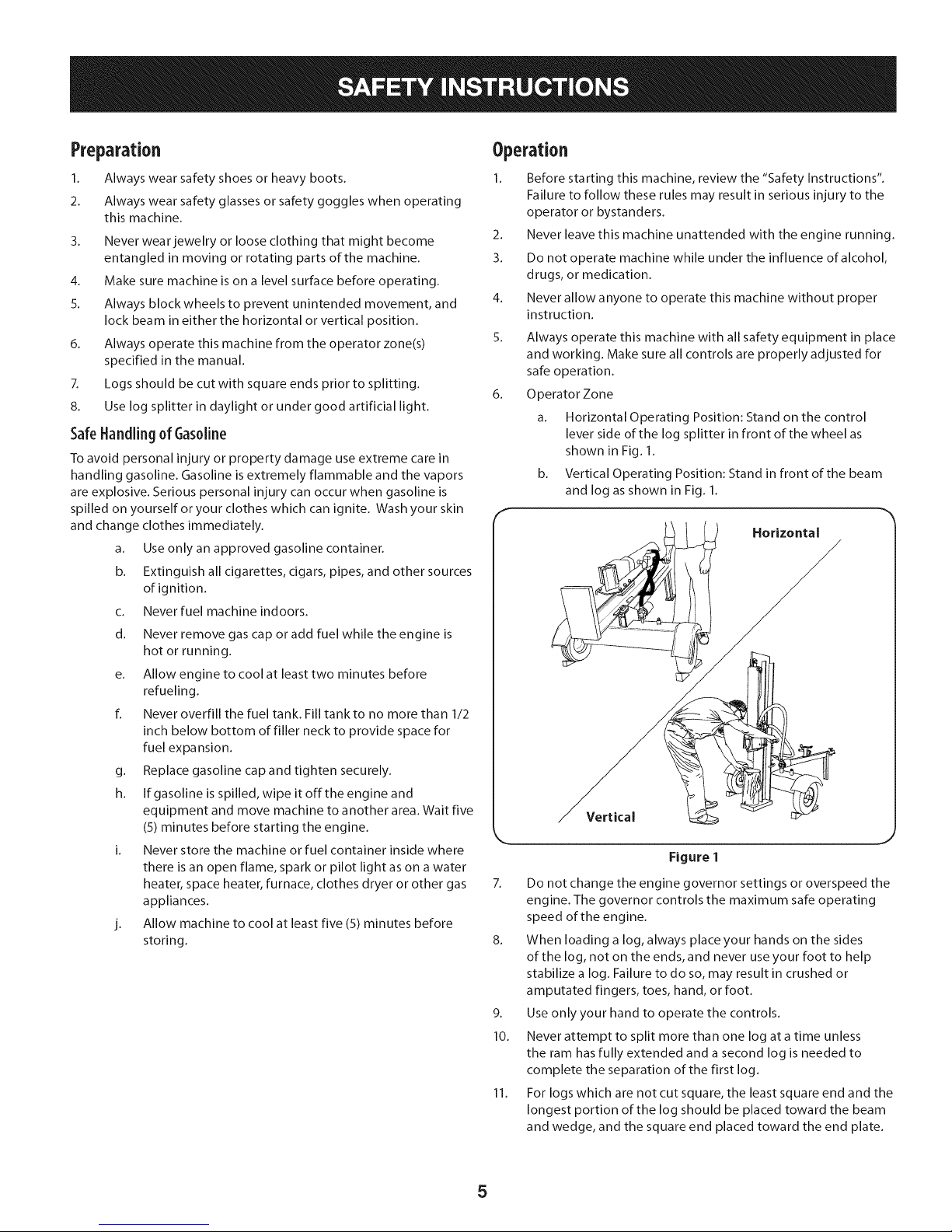
Operator Zone
a. Horizontal Operating Position: Stand on the control
b. Vertical Operating Position: Stand in front of the beam
7. Do not change the engine governor settings or overspeed the
engine. The governor controls the maximum safe operating
speed of the engine.
8. When loading a log, always place your hands on the sides
of the log, not on the ends, and never use your foot to help
stabilize a log. Failure to do so, may result in crushed or
amputated fingers, toes, hand, or foot.
9. Use only your hand to operate the controls.
10. Never attempt to split more than one log at a time unless
the ram has fully extended and a second log is needed to
complete the separation of the first log.
11. For logs which are not cut square, the least square end and the
longest portion of the log should be placed toward the beam
and wedge, and the square end placed toward the end plate.
lever side of the log splitter in front of the wheel as
shown in Fig. 1.
and log as shown in Fig. 1.
Horizontal
Vertical
Figure 1
Page 6
12.
Whensplittingintheverticalposition,stabilizethelogbefore
movingthecontrol.Splitasfollows:
a. Placelogontheendplateandturnuntilitleansagainst
thebeamandisstable.
b. Whensplittingextralargeorunevenlogs,thelogmust
bestabilizedwithwoodenshimsorsplitwoodbetween
thelogandendplateorground.
12. Alwayskeepfingersawayfromanycracksthatopeninthelog
whilesplitting.Theycanquicklycloseandpinchoramputate
yourfingers.
13. Keepyourworkareaclean.Immediatelyremovesplitwood
aroundthemachinesoyoudonotstumbleoverit.
14. Nevermovethismachinewhiletheengineisrunning.
15. Thismachineshouldnotbetowedonanystreet,highwayor
publicroadwithoutcheckingtheexistingfederal,state,or
localvehiclerequirements.Anylicensingormodificationssuch
astaillights,etc.,neededtocomply,isthesoleresponsibility
ofthepurchaser.Ifa"StatementofOrigin"isrequiredinyour
state,seeyourlocaldealer.
16. Donottowmachineover45mph.
17. SeeTransportingtheLogSplittersectioninthismanualfor
propertowinginstructionsonceallfederal,local,orstate
requirementsaremet.
MaintenanceandStorage
This machine is equipped with an internal combustion engine and
should not be used on or near any unimproved forest-covered,
brush-covered or grass-covered land unless the engine's exhaust
system is equipped with a spark arrester meeting applicable local
or state laws (if any)
1. Stop the engine, disconnect the spark plug and ground it
against the engine before cleaning, or inspecting the machine.
2. Stop the engine and relieve hydraulic system pressure before
repairing or adjusting fittings, hoses, tubing, or other system
components.
3. To prevent fires, clean debris and chaff from the engine
and muffler areas. If the engine is equipped with a spark
attester muffler, clean and inspect it regularly according to
manufacturers instructions. Replace if damaged.
4. Periodically check that all nuts and bolts, hose clamps, and
hydraulic fittings are tight to be sure equipment is in safe
working condition.
5. Check all safety guards and shields to be sure they are in the
proper position. Never operate with safety guards, shields, or
other protective features removed.
6_
The pressure relief valve is preset at the factory. Do not adjust
the valve.
7.
Never attempt to move this machine over hilly or uneven
terrain without atow vehicle or adequate help.
8.
For your safety, replace all damaged or worn parts immediately
with original equipment manufacturer's (O.E.M.) parts only.
"Use of parts which do not meet the original equipment
specifications may lead to improper performance and
compromise safety!"
9_
Do not alter this machine in any manner, alterations such as
attaching a rope or extension to the control handle, or adding
to the width or height of the wedge may result in personal
injury.
10.
According to the Consumer Products Safety Commission
(CPSC) and the U.S. Environmental Protection Agency (EPA),
this product has an Average Useful Life of seven (7) years, or
130 hours of operation. At the end of the Average Useful Life
have the machine inspected annually by an authorized service
dealer to ensure that all mechanical and safety systems are
working properly and not worn excessively. Failure to do so
can result in accidents, injuries or death.
SparkArrestor
Ira spark arrester is used, it should be maintained in effective
working order by the operator. In the State of California the above
is required by law (Section 4442 of the California Public Resources
Code). Other states may have similar laws. Federal laws apply on
federal lands.
A spark attester for the muffler is available through your nearest
Sears Parts and Repair Service Center.
6
Page 7
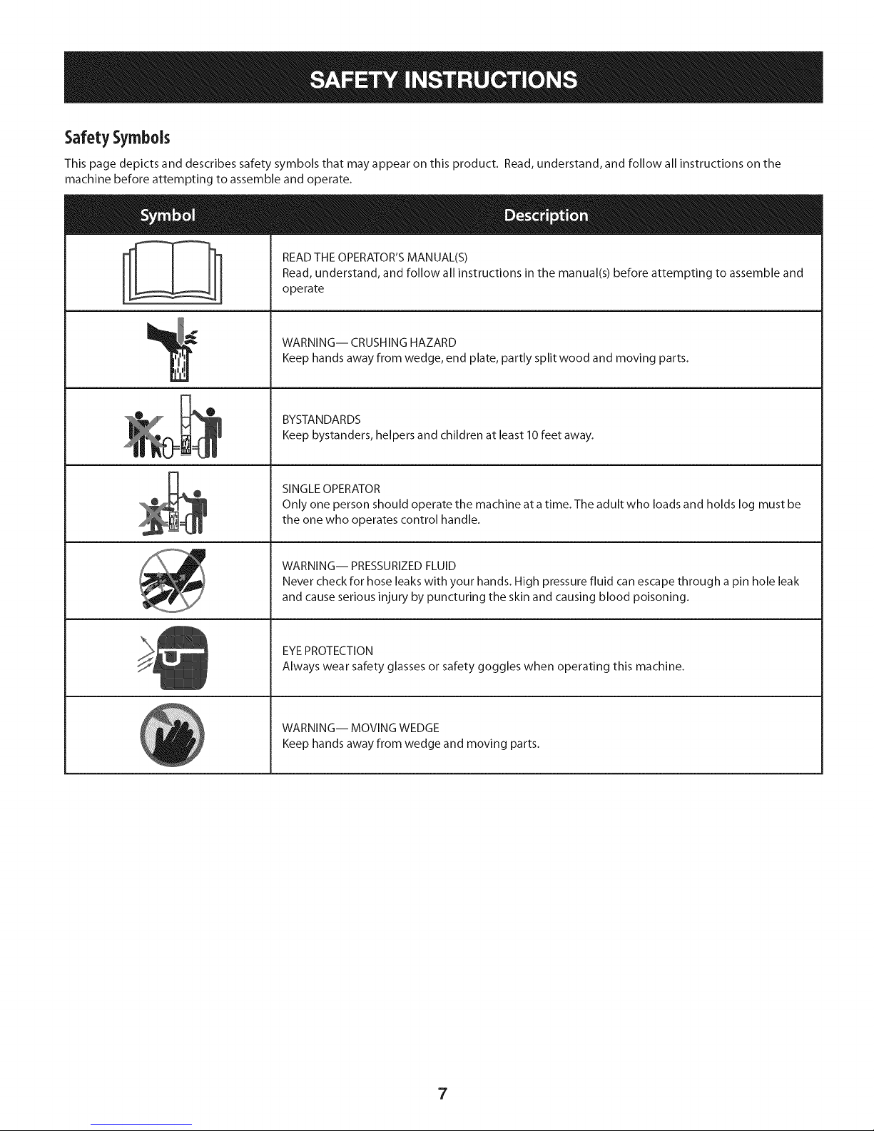
SafetySymbols
This page depicts and describes safety symbols that may appear on this product. Read, understand, and follow all instructions on the
machine before attempting to assemble and operate.
A
READ THE OPERATOR'S MANUAL(S)
Read, understand, and follow all instructions in the manual(s) before attempting to assemble and
operate
WARNING-- CRUSHING HAZARD
Keep hands away from wedge, end plate, partly split wood and moving parts.
BYSTANDARDS
Keep bystanders, helpers and children at least 10feet away.
SINGLE OPERATOR
Only one person should operate the machine at a time. The adult who loads and holds log must be
the one who operates control handle.
WARNING-- PRESSURIZED FLUID
Never check for hose leaks with your hands. High pressure fluid can escape through a pin hole leak
and cause serious injury by puncturing the skin and causing blood poisoning.
EYEPROTECTION
Always wear safety glasses or safety goggles when operating this machine.
WARNING-- MOVING WEDGE
Keep hands away from wedge and moving parts.
7
Page 8
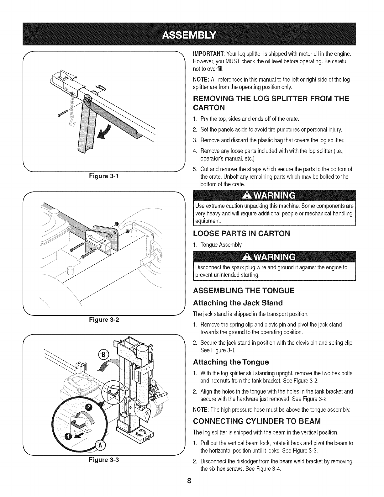
Figure 3=1
IMPORTANT:Yourlogsplitterisshippedwithmotoroil intheengine.
However,you MUSTchecktheoil levelbeforeoperating.Becareful
notto overfill.
NOTE:All referencesinthis manualtotheleftor rightsideof thelog
splitterarefromthe operatingpositiononly.
REMOVING THE LOG SPLITTER FROM THE
CARTON
1. Prythe top,sidesandendsoffofthecrate.
2. Setthe panelsasidetoavoidtirepuncturesorpersonalinjury.
3. Removeanddiscardtheplasticbagthatcoversthelogsplitter.
4. Removeanyloosepartsincludedwithwiththelogsplitter(i.e.,
operator'smanual,etc.)
_J
5. Cutand removethestrapswhichsecurethepartsto thebottomof
thecrate.Unboltanyremainingpartswhichmaybe boltedtothe
bottomof thecrate.
Useextremecautionunpackingthismachine.Somecomponentsare
veryheavyandwill requireadditionalpeopleor mechanicalhandling
equipment.
LOOSE PARTS IN CARTON
\
... j
Figure 3=2
1. TongueAssembly
Disconnectthe sparkplugwireandgroundit againsttheengineto
preventunintendedstarting.
ASSEMBLING THE TONGUE
Attaching the Jack Stand
Thejackstandisshippedinthetransportposition.
1. Removethespringclipandclevispinandpivotthejackstand
towardsthegroundtothe operatingposition.
2. Securethejackstandinpositionwiththeclevispinandspringclip.
See Figure3-1.
Attaching the Tongue
1. Withthelogsplitterstill standingupright,removethe twohexbolts
and hexnutsfromthe tankbracket.SeeFigure3-2.
2. Aligntheholesinthetonguewiththeholesinthetankbracketand
securewiththehardwarejustremoved.See Figure3-2.
NOTE:Thehighpressurehosemustbe abovethetongueassembly.
CONNECTING CYLINDER TO BEAM
Figure 3=3
Thelogsplitterisshippedwiththebeamin theverticalposition.
1. Pulloutthe verticalbeamlock,rotateit backandpivotthebeamto
thehorizontalpositionuntilitlocks.SeeFigure3-3.
2. Disconnectthedislodgerfromthebeamweldbracketby removing
thesix hexscrews.SeeFigure3-4.
8
Page 9
.
Disconnectthelogcradlefromthebeamonthesideofthe control
valve.SeeFigure3-5.
.
Liftand slidethe cylinderup tothe topof beamandintotheweld
brackets.
5. Attachthedislodgeroverthewedgeassemblyandsecureit to the
weldbracketswiththe previouslyremovedhardware.
NOTE:Oncethesixhex screwsaretightened,theremaybeaslight
gapbetweenthe dislodgerandtheweldbrackets.Thisgapisnormal.
6. Reattachthelogcradletothe sideof thebeamwiththecontrol
valve,aligningtheendsof thecradlewiththebeamflanges.
7. Rollthelog splitteroffthebottomcrate.
PREPARING THE LOG SPLITTER
1. Lubricatethebeamarea(wherethesplittingwedgewillslide)with
engineoil.Do notuse grease.
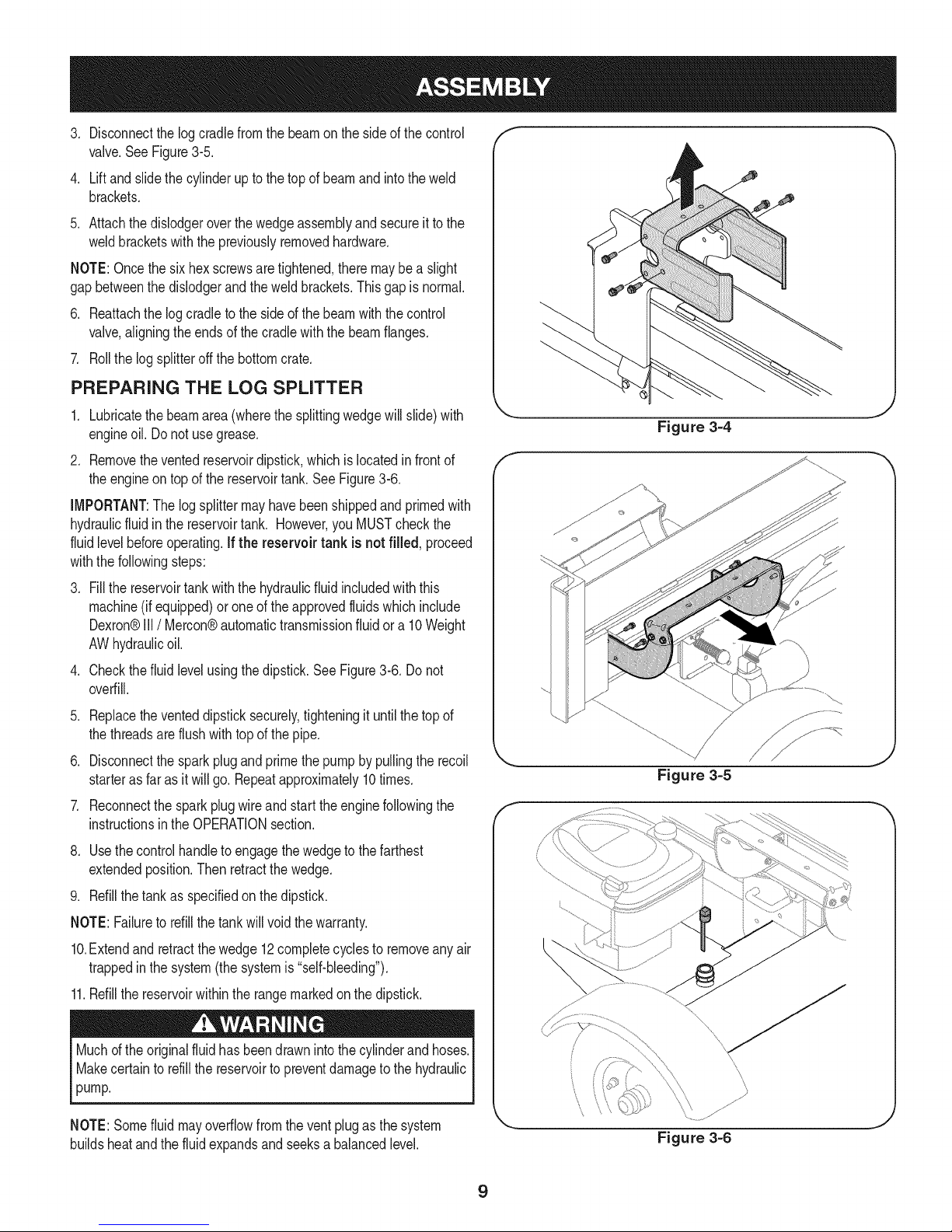
2. Removetheventedreservoirdipstick,whichis locatedinfrontof
theengineontop ofthe reservoirtank.SeeFigure3-6.
IMPORTANT:Thelogsplittermayhavebeenshippedandprimedwith
hydraulicfluidin the reservoirtank. However,youMUSTcheckthe
fluidlevelbeforeoperating.Ifthe reservoir tank is not filled, proceed
withthefollowingsteps:
.
Fillthe reservoirtankwiththehydraulicfluidincludedwiththis
machine(if equipped)oroneof theapprovedfluidswhichinclude
Dexron®III/ Mercon®automatictransmissionfluidora 10Weight
AWhydraulicoil.
.
Checkthefluidlevelusingthedipstick.SeeFigure3-6.Do not
overfill.
.
Replacetheventeddipsticksecurely,tighteningit untilthetopof
thethreadsareflushwithtop ofthe pipe.
6. Disconnectthesparkplugandprimethepumpby pullingthe recoil
starteras faras itwill go.Repeatapproximately10times.
7. Reconnectthesparkplugwireandstartthe enginefollowingthe
instructionsin theOPERATIONsection.
8. Usethecontrolhandleto engagethewedgetothe farthest
extendedposition.Thenretractthewedge.
9. Refillthetankas specifiedonthedipstick.
NOTE:Failuretorefillthetankwill voidthe warranty.
10.Extendand retractthewedge12completecyclesto removeanyair
trappedinthe system(thesystemis"self-bleeding").
11.Refillthereservoirwithintherangemarkedonthedipstick.
Muchd theoriginalfluidhasbeendrawnintothecylinderandhoses.
Makecertainto refillthereservoirtopreventdamageto thehydraulic
pump.
Figure 3=4
Figure 3=5
\\\
"x
,J
\
\
NOTE:Somefluidmayoverflowfromtheventplugasthesystem
buildsheatandthefluidexpandsandseeksa balancedlevel.
Figure 3=6
9
Page 10
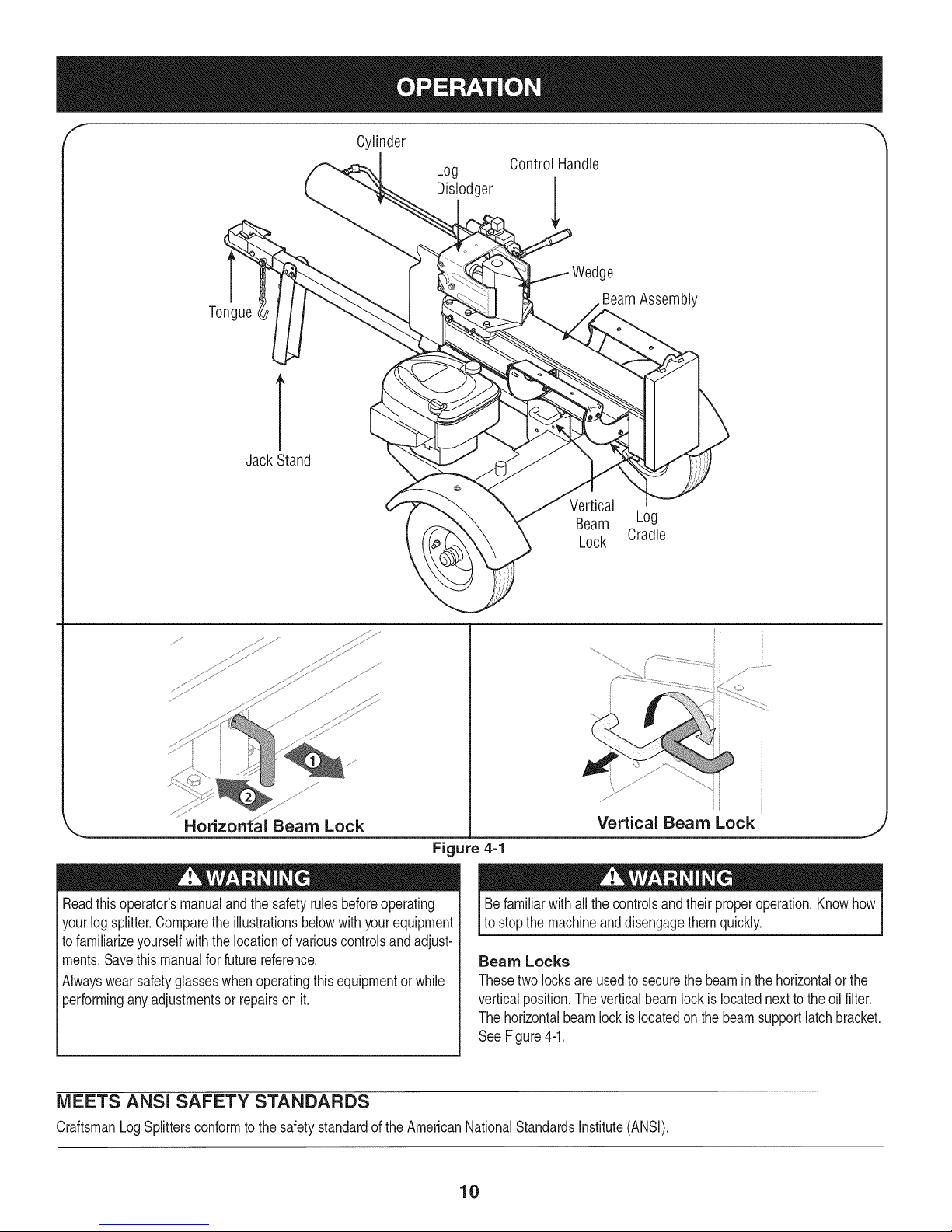
Cylinder
Log
Dislodger
Control Handle
e
Tongue
BeamAssembly
1
JackStand
Vertical
Beam Log
Lock Cradle
,_ Horizontai Beam Lock
Readthisoperator'smanualandthesafetyrulesbeforeoperating
yourlogsplitter.Comparetheillustrationsbelowwithyourequipment
tofamiliarizeyourselfwiththelocationofvariouscontrolsandadjust-
ments.Savethismanualforfuturereference.
Alwayswearsafetyglasseswhenoperatingthisequipmentorwhile
performinganyadjustmentsor repairson it.
MEETS ANSI SAFETY STANDARDS
CraftsmanLogSplittersconformtothesafetystandardoftheAmericanNationalStandardsInstitute(ANSI).
Vertical Beam Lock
Figure 4=1
Befamiliarwithallthecontrolsandtheirproperoperation.Knowhow
tostopthe machineanddisengagethemquickly.
Beam Locks
Thesetwo locksareusedto securethebeamin thehorizontalor the
verticalposition.Theverticalbeamlockis locatednexttotheoil filter.
Thehorizontalbeamlockislocatedonthe beamsupportlatchbracket.
See Figure4-1.
10
J
Page 11
ENGINE CONTROLS
Stop Switch
Pushthe switchtoON priortochokingfor theenginestart;pushto
OFFto shutthe enginedown.
Choke Control
Thechokecontrolis usedto chokeoff thecarburetorandassistin
startingtheengine.
Starter Handle
Thestarterhandleis locatedonthe engine.Pullthe starterhandleto
startengine.
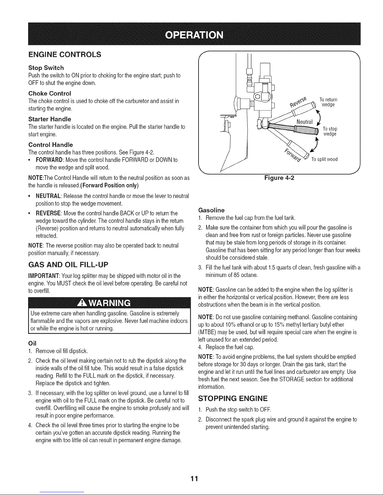
Control Handle
Thecontrolhandlehasthreepositions.SeeFigure4-2.
• FORWARD:MovethecontrolhandleFORWARDor DOWNto
movethewedgeand splitwood.
NOTE:TheControlHandlewillreturntotheneutralpositionassoonas
thehandleisreleased.(ForwardPosition only)
NEUTRAL:Releasethecontrolhandleor movethelevertoneutral
positiontostopthewedgemovement.
REVERSE:MovethecontrolhandleBACKorUPto returnthe
wedgetowardthecylinder.Thecontrolhandlestaysinthe return
(Reverse)positionand returnsto neutralautomaticallywhenfully
retracted.
NOTE:The reversepositionmayalsobeoperatedbacktoneutral
positionmanually,ifnecessary.
GAS AND OiL FILL-UP
iMPORTANT:Yourlog splittermaybeshippedwithmotoroil inthe
engine.YouMUSTcheckthe oillevelbeforeoperating.Becarefulnot
tooverfill.
Useextremecarewhenhandlinggasoline.Gasolineisextremely
flammableandthe vaporsareexplosive.Neverfuelmachineindoors
or whilethe engineishotor running.
Oil
1. Removeoilfill dipstick.
2. Checktheoil levelmakingcertainnottorubthedipstickalongthe
insidewallsoftheoil fill tube.Thiswouldresultina falsedipstick
reading.Refillto theFULLmarkon thedipstick,if necessary.
Replacethedipstickandtighten.
3. If necessary,withthelogsplitteronlevelground,usea funnelto fill
enginewithoiltothe FULLmarkonthedipstick.Becarefulnotto
overfill.Overfillingwillcausetheenginetosmokeprofuselyandwill
resultinpoorengineperformance.
4. Checktheoil levelthreetimespriortostartingtheengineto be
certainyou'vegottenan accuratedipstickreading.Runningthe
enginewithtoolittleoilcan resultinpermanentenginedamage.
To return
wedge
Tostop
wedge
2
To split wood
Figure 4=2
Gasoline
1. Removethefuelcapfromthefuel tank.
2. Makesurethe containerfromwhichyouwill pourthegasolineis
cleanandfree fromrustorforeignparticles.Neverusegasoline
thatmaybe stalefromlongperiodsof storageinitscontainer.
Gasolinethathasbeensittingforany periodlongerthanfourweeks
shouldbeconsideredstale.
3. Fillthe fueltankwithabout 1.5quartsof clean,freshgasolinewitha
minimumof85octane.
NOTE:Gasolinecan beaddedtotheenginewhenthelog splitteris
ineitherthe horizontalorverticalposition.However,thereareless
obstructionswhenthe beamisintheverticalposition.
NOTE:Donotusegasolinecontainingmethanol.Gasolinecontaining
uptoabout10%ethanolor upto 15%methyltertiarybutylether
(MTBE)maybe used,butwill requirespecialcarewhentheengineis
Idt unusedforanextendedperiod.
4. Replacethefuelcap.
NOTE:Toavoidengineproblems,thefuel systemshouldbe emptied
beforestoragefor30 daysor longer.Drainthegas tank,startthe
engineand letit rununtilthe fuellinesandcarburetorareempty.Use
freshfuelthe nextseason.Seethe STORAGEsectionforadditional
information.
STOPPING ENGINE
1. PushthestopswitchtoOFE
2. Disconnectthesparkplugwireandgroundit againsttheengineto
preventunintendedstarting.
11
Page 12
STARTING ENGINE
1. Attachthe sparkplugwiretothesparkplug.Makecertainthemetal
capon the endofthe sparkplugisfastenedsecurelyoverthemetal
tiponthe sparkplug.
2. Pushthe stopswitchtoON.
3. Movethechokecontrolto theCHOKEposition.
4. Graspthe starterhandleandpullthe ropeoutslowlyuntilthe
enginereachesitsstartof compressioncycle (ropewillpullslightly
harderatthispoint).
5. Pulltheropewitha rapid,continuous,fullarmstroke.Keepafirm
griponthestarterhandle.Lettheroperewindslowly.
6. Repeat,if necessary,untiltheenginestarts.Slowlyadjustthe
choketowardtheRUNposition.Waituntiltheenginerunssmoothly
beforeeachchokeadjustment.
7. Iftheenginefalters,movethecontrolleverto theCHOKEposition,
thenslowlybacktothe RUNposition.
8. Ifweatheriscold, runthewedgeupor downthebeam6 to8 times
tocirculatethe
Whenstartinga warmengine,the mufflerandsurroundingareasare
hotandcan causea burn.Donottouchtheseareas.
USING THE LOG SPLITTER
.
Placethe logsplitterondry,levelground.
2.
Placethe beamineitherthehorizontalorverticalpositionandlock
itin placewiththeappropriatelockingrod.
.
Blockthefrontandbackof bothwheels.
4.
Placethe logagainsttheend plateandonlysplitwoodin the
directionofthegrain.
5. Tostabilizethelog,placeyour handonlyonthesidesofthelog.
Neverplaceyour handon the endbetweenthe logandthe
splittingwedge.
6. Onlyoneadultshouldstabilizethelogandoperatethecontrol
handle,sotheoperatorhasfull controloverthe logand thesplitting
wedge.
Control Handle
1. MovethecontrolhandleFORWARDor DOWNtosplitwood.
2. Releasethecontrolhandletostopthewedgemovement.
3. MovethecontrolhandleBACKor UPto returnthewedge.
Log Dislodger
Thelogdislodgerisdesignedto removeanypartiallysplitwoodfrom
thewedge.Thismayoccurwhilesplittinglargediameterwoodor
freshlycutwood.
Neverremovepartiallysplitwoodfromthewedgewithyourhands.
Fingersmaybecometrappedbetweenthesplitwood.
1. Toremovepartiallysplitwoodfromthewedge,movethecontrol
handletothe REVERSEpositionuntilthewedgeisfullyretractedto
allowthe splitwoodportiontocontactthe logdislodger.
2. Onceremovedfromthewedgewiththe logdislodger,splitthe
woodfromthe oppositeendorin anotherlocation.
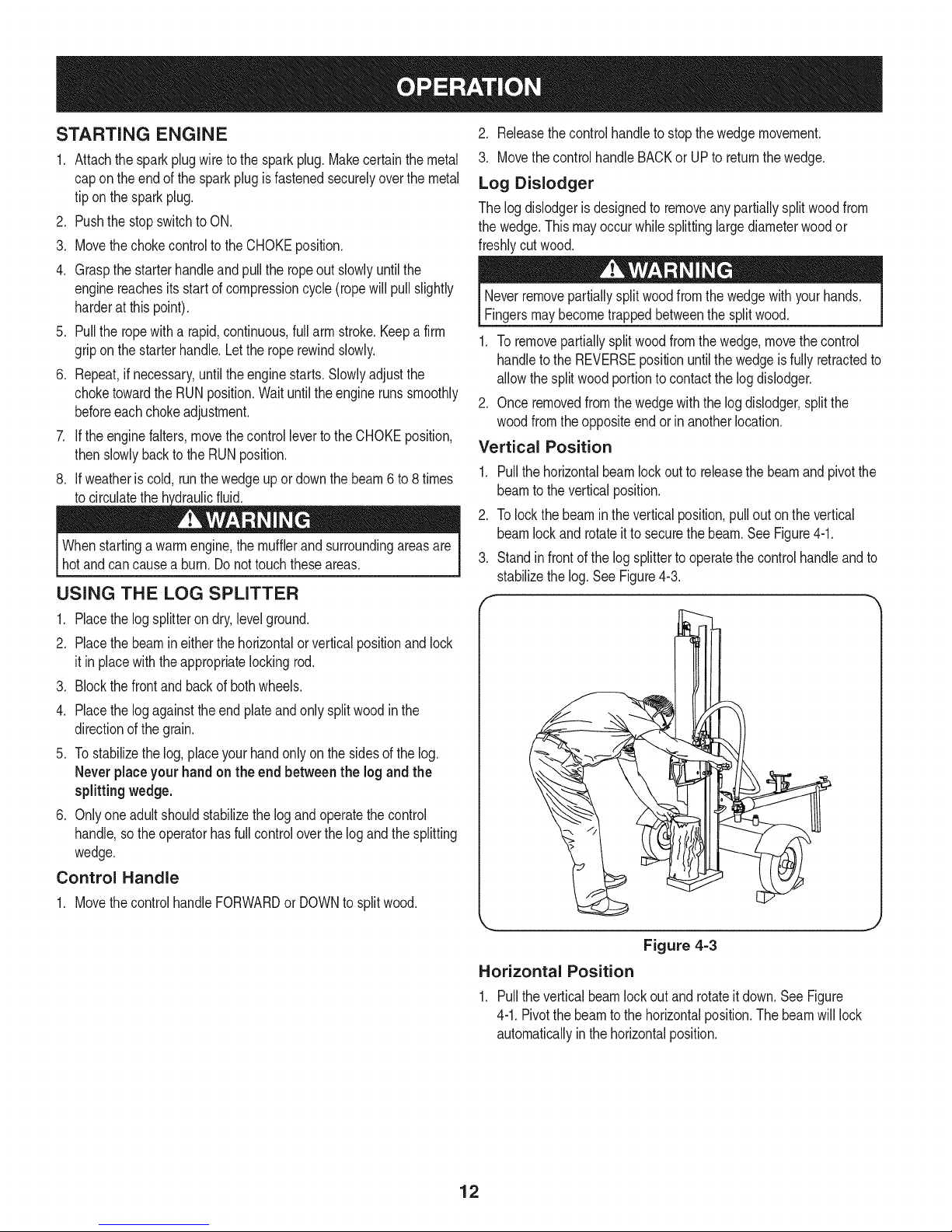
Vertical Position
1. Pullthehorizontalbeamlockoutto releasethebeamandpivotthe
beamto theverticalposition.
2. Tolockthebeamintheverticalposition,pulloutonthe vertical
beamlockand rotateit tosecurethe beam.See Figure4-1.
3. Standin frontof thelogsplittertooperatethecontrolhandleandto
stabilizethelog.SeeFigure4-3.
Figure 4=3
Horizontal Position
1. Pulltheverticalbeamlockout androtateitdown.SeeFigure
4-1.Pivotthe beamto thehorizontalposition.Thebeamwilllock
automaticallyinthehorizontalposition.
12
Page 13
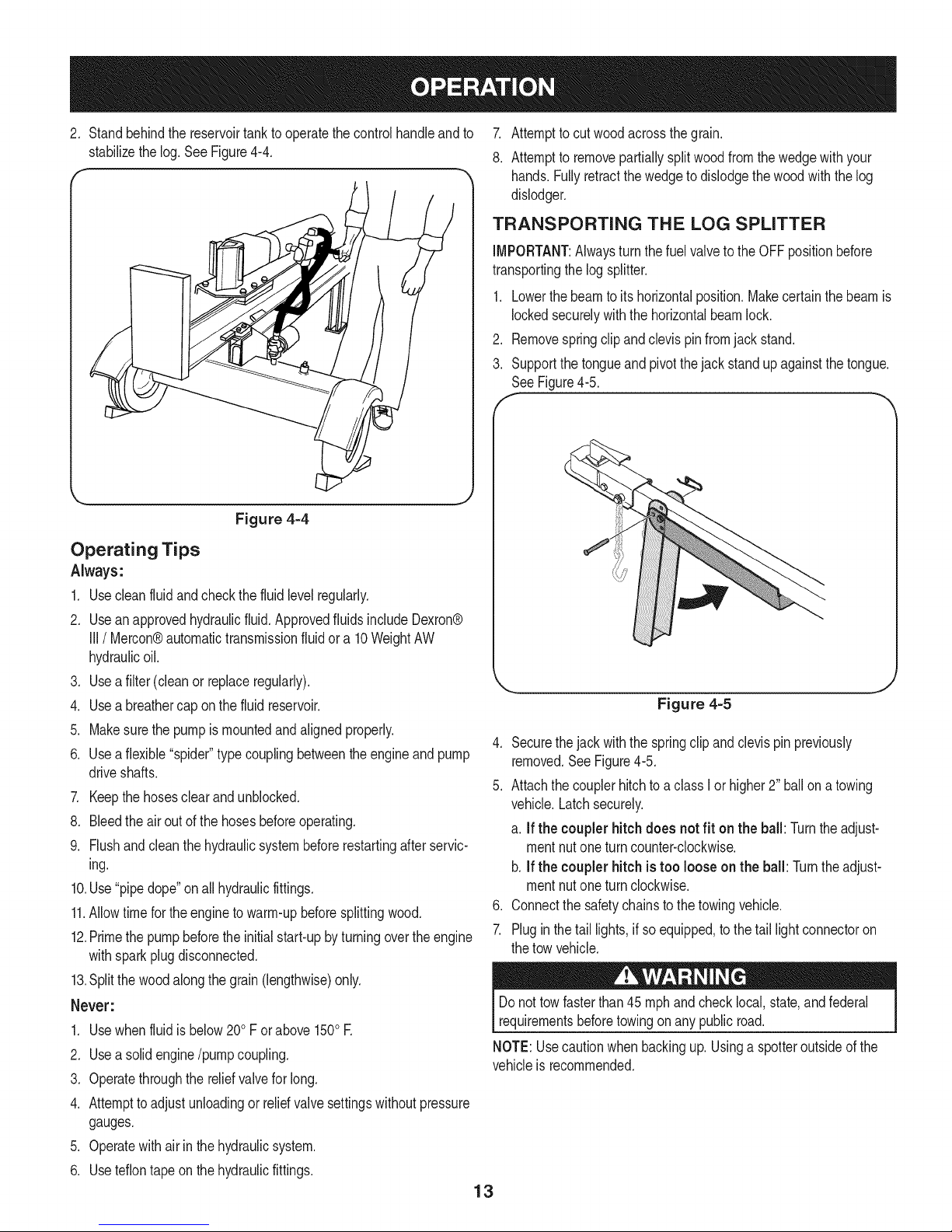
2, Standbehindthe reservoirtanktooperatethecontrolhandleandto 7.
stabilizethelog,See Figure4-4, 8,
TRANSPORTING THE LOG SPLITTER
transportingthelogsplitter.
2. Removespringclipandclevispinfromjackstand.
3. Supportthetongueandpivotthejack standup againstthetongue.
Figure 4=4
Operating Tips
Always:
1. Usecleanfluidandcheckthefluidlevelregularly.
2. Useanapprovedhydraulicfluid.ApprovedfluidsincludeDexron®
III/ Mercon®automatictransmissionfluidora 10WeightAW
hydraulicoil.
3. Useafilter(cleanor replaceregularly).
4. Usea breathercaponthefluid reservoir.
5. Makesurethe pumpis mountedandalignedproperly.
6. Useaflexible"spider"typecouplingbetweentheengineandpump
driveshafts.
7. Keepthehosesclear andunblocked.
8. Bleedtheairout ofthehosesbeforeoperating.
9. Flushandcleanthe hydraulicsystembeforerestartingafterservic-
ing.
10.Use"pipedope"onallhydraulicfittings.
11.Allowtimefortheenginetowarm-upbeforesplittingwood.
12.Primethe pumpbeforetheinitialstart-upbyturningovertheengine
withsparkplugdisconnected.
13.Splitthewoodalongthe grain(lengthwise)only.
Never:
1. Usewhenfluidis below200Forabove1500E
2. Usea solidengine/pumpcoupling.
3. Operatethroughthereliefvalveforlong.
4. Attempttoadjustunloadingorrelid valvesettingswithoutpressure
gauges.
5. Operatewithairin thehydraulicsystem.
6. Useteflontapeon thehydraulicfittings.
4. Securethejack withthe springclipandclevispinpreviously
5. Attachthe couplerhitchtoa classIor higher2" ballona towing
6. Connectthe safetychainstothetowingvehicle.
vehicleis recommended.
13
Attempttocutwoodacrossthe grain.
Attemptto removepartiallysplitwoodfromthewedgewithyour
hands.Fullyretractthewedgeto dislodgethewoodwiththe log
dislodger.
IMPORTANT:Alwaysturnthe fuelvalveto theOFFpositionbefore
1. Lowerthebeamto itshorizontalposition.Makecertainthe beamis
lockedsecurelywiththe horizontalbeamlock.
SeeFigure4-5.
Figure 4=5
removed.SeeFigure4-5.
vehicle.Latchsecurely.
a. If the couplerhitchdoes notfit on the ball: Turntheadjust-
mentnutone turncounter-clockwise.
b.If thecouplerhitch is too loose onthe ball: Turntheadjust-
mentnutone turnclockwise.
7. Plugin thetail lights,if soequipped,tothe taillight connectoron
thetowvehicle.
Donot towfasterthan45mphandchecklocal,state,andfederal
requirementsbeforetowingonanypublicroad.
NOTE:Usecautionwhenbackingup.Usinga spotteroutsideofthe
Page 14
f
Adjustment
Bolt
.Gib
Jam Nut
Lock Nut
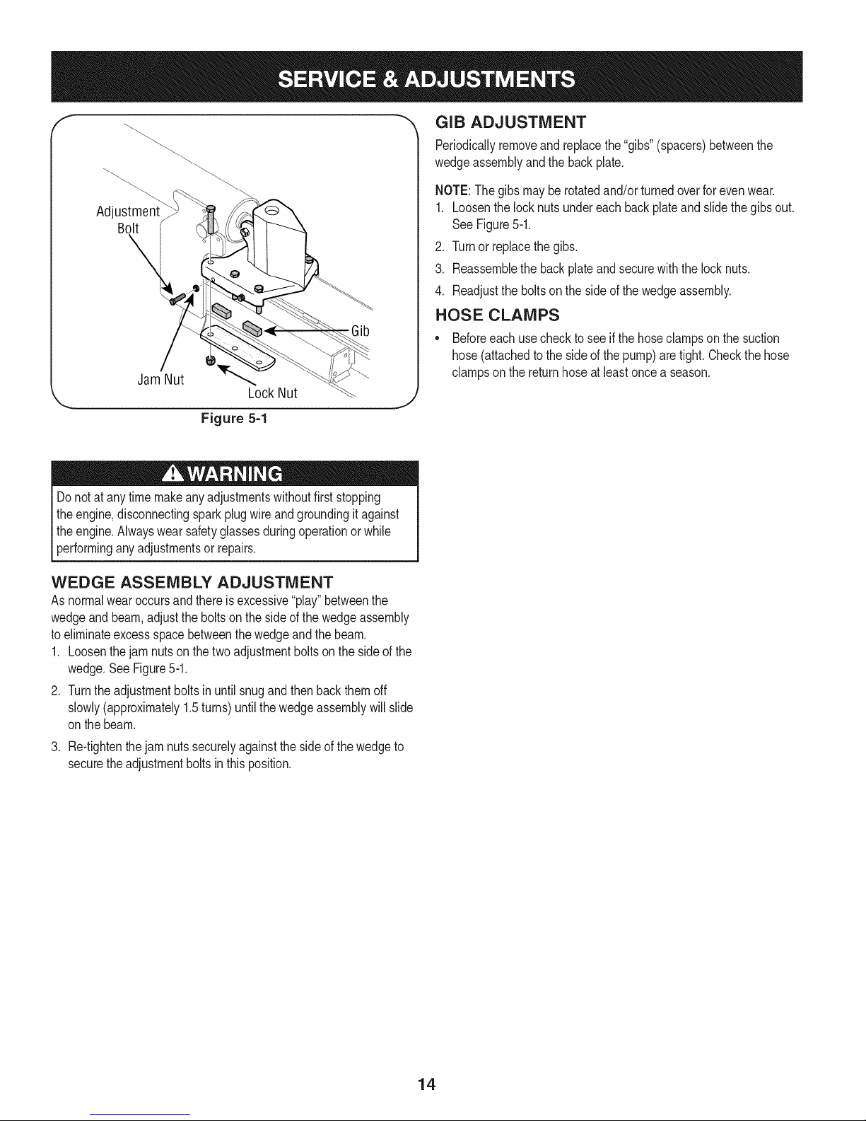
Figure 5=1
Donotatany timemakeanyadjustmentswithoutfirststopping
theengine,disconnectingsparkplugwireandgroundingit against
theengine.Alwayswearsafetyglassesduringoperationor while
[performng anyadjustmentsor repars.
"_ GIB ADJUSTMENT
Periodicallyremoveandreplacethe"gibs"(spacers)betweenthe
wedgeassemblyandthe backplate,
NOTE:The gibsmaybe rotatedand/orturnedoverforevenwear.
1. Loosenthelocknutsundereachbackplateandslidethe gibsout.
See Figure5-1.
2. Turnor replacethegibs.
3. Reassemblethe backplateandsecurewiththelocknuts.
4. Readjusttheboltsonthe sideofthewedgeassembly.
HOSE CLAMPS
• Beforeeachusechecktoseeif thehoseclampsonthe suction
hose(attachedtothe sideof thepump)aretight.Checkthehose
clampsonthe returnhoseatleastoncea season.
WEDGE ASSEMBLY ADJUSTMENT
Asnormalwearoccursandthereis excessive"play"betweenthe
wedgeandbeam,adjustthe boltsonthesideofthe wedgeassembly
toeliminateexcessspacebetweenthewedgeandthebeam.
1. Loosenthejam nutsonthe twoadjustmentboltson thesideofthe
wedge.SeeFigure5-1.
2. Turntheadjustmentboltsinuntilsnugandthenbackthemoff
slowly(approximately1.5turns)untilthewedgeassemblywillslide
onthebeam.
.
Re-tightenthejam nutssecurelyagainstthesideofthewedgeto
securetheadjustmentboltsinthisposition.
14
Page 15
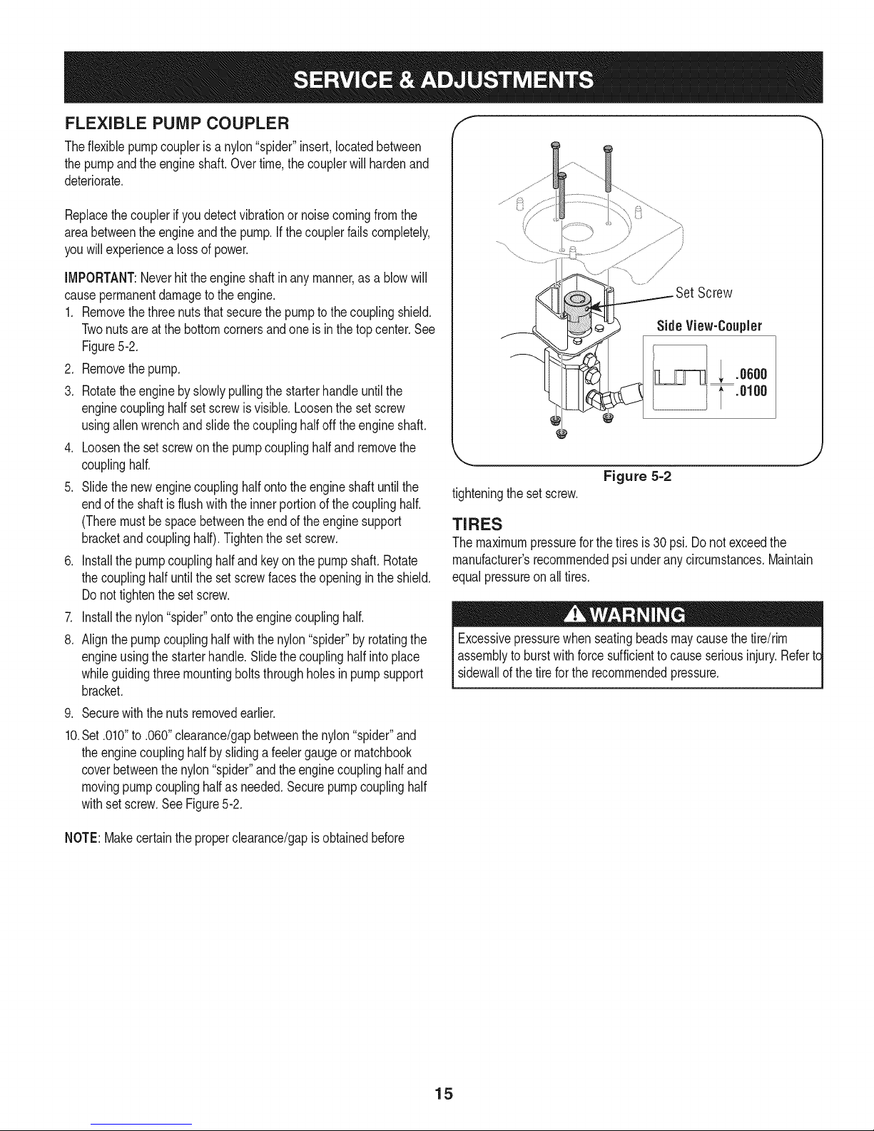
FLEXIBLE PUMP COUPLER
Theflexiblepumpcoupleris a nylon"spider"insert,locatedbetween
thepumpandtheengineshaft.Overtime,the couplerwillhardenand
deteriorate.
Replacethecouplerifyou detectvibrationornoisecomingfromthe
areabetweenthe engineandthepump.Ifthecouplerfailscompletely,
youwill experiencea lossofpower.
]i!ill
iMPORTANT:Neverhittheengineshaftin anymanner,asa blowwill
causepermanentdamagetothe engine.
1. Removethethreenutsthatsecurethepumptothecouplingshield.
Twonutsareatthe bottomcornersandoneis inthetop center.See
Figure5-2.
2. Removethepump.
3. Rotatetheenginebyslowlypullingthestarterhandleuntilthe
enginecouplinghalfsetscrewis visible.Loosenthesetscrew
usingallenwrenchandslidethecouplinghalfoff the engineshaft.
4. Loosenthesetscrewonthe pumpcouplinghalfandremovethe
couplinghalf.
5. Slidethenewenginecouplinghalfontotheengineshaftuntil the
endofthe shaftis flushwiththeinnerportionofthe couplinghalf.
(Theremustbespacebetweenthe endoftheenginesupport
bracketandcouplinghalf).Tightenthesetscrew.
6. Installthe pumpcouplinghalfandkeyonthepumpshaft.Rotate
thecouplinghalfuntilthesetscrewfacestheopeningin theshield.
Donottightentheset screw.
7. Installthe nylon"spider"ontotheenginecouplinghalf.
8. Alignthepumpcouplinghalfwiththenylon"spider"byrotatingthe
engineusingthe starterhandle.Slidethecouplinghalfinto place
whileguidingthreemountingboltsthroughholesinpumpsupport
bracket.
9. Securewiththe nutsremovedearlier.
10.Set.010"to .060"clearance/gapbetweenthenylon"spider"and
theenginecouplinghalfbyslidinga feelergaugeor matchbook
coverbetweenthenylon"spider"andtheenginecouplinghalfand
movingpumpcouplinghalfas needed.Securepumpcouplinghalf
withsetscrew.SeeFigure5-2.
/
Screw
Side View-Coupler
; .oooo
.0100
J
Figure 5=2
tighteningthe set screw.
TIRES
Themaximumpressureforthetiresis30psi.Donotexceedthe
manufacturer'srecommendedpsiunderany circumstances.Maintain
equalpressureonall tires.
Excessivepressurewhenseatingbeadsmaycausethetire/rim
assemblyto burstwithforcesufficienttocauseseriousinjury.Refertc
sidewallofthe tirefor therecommendedpressure.
NOTE:Makecertainthe properclearance/gapisobtainedbefore
15
Page 16
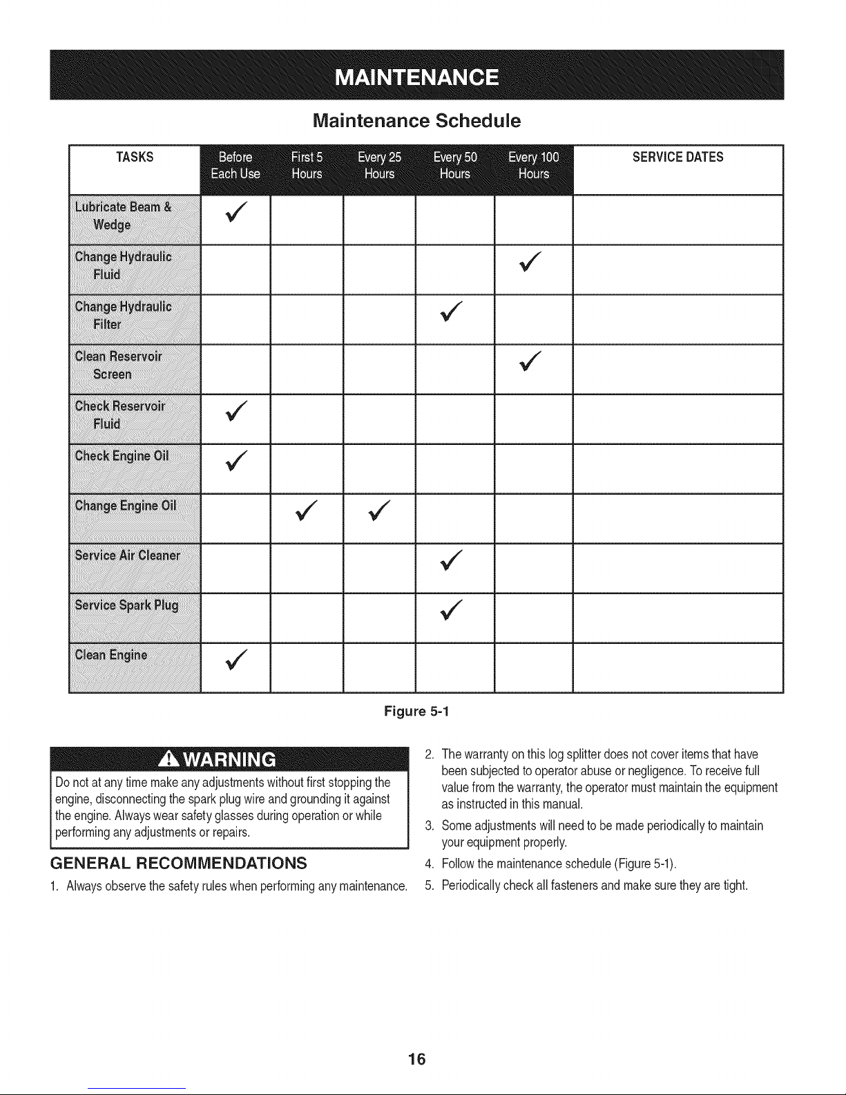
Maintenance Schedule
TASKS
SERVICEDATES
v
Figure 5=1
Donotatany timemakeanyadjustmentswithoutfirststoppingthe
engine,disconnectingthesparkplugwireandgroundingit against
theengine.Alwayswearsafetyglassesduringoperationor while
performinganyadjustmentsor repairs.
GENERAL RECOMMENDATIONS
1. Alwaysobservethesafetyruleswhenperforminganymaintenance.
.
Thewarrantyonthis logsplitterdoesnotcoveritemsthathave
beensubjectedtooperatorabuseor negligence.Toreceivefull
valuefromthe warranty,the operatormustmaintaintheequipment
asinstructedinthis manual.
3. Someadjustmentswillneedto bemadeperiodicallytomaintain
yourequipmentproperly.
4. Followthemaintenanceschedule(Figure5-1).
5. Periodicallycheckallfastenersandmakesuretheyaretight.
16
Page 17
HYDRAULIC FLUID AND iNLET FILTER
Checkthehydraulicfluid levelinthelogsplitterreservoirtank
beforeeachuse.Maintainthe fluidlevelwithintherangespecified
onthedipstickat all times.
Changethehydraulicfluid inthereservoirevery100hoursof
operation.Followthe stepsbelow:
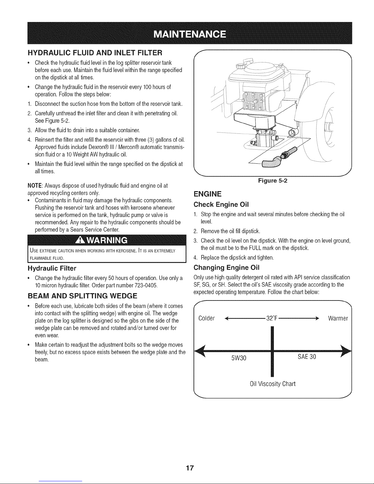
Disconnectthesuctionhosefromthe bottomofthereservoirtank.
2. Carefullyunthreadthe inletfilterandclean itwithpenetratingoil.
SeeFigure5-2.
3. Allowthefluidto drainintoa suitablecontainer.
4. Reinsertthefilterandrefillthe reservoirwiththree(3) gallonsofoil.
ApprovedfluidsincludeDexron®III/Mercon® automatictransmis-
sionfluid ora 10WeightAWhydraulicoil.
• Maintainthefluidlevelwithintherangespecifiedon thedipstickat
alltimes.
NOTE:Alwaysdisposeofusedhydraulicfluidandengineoilat
approvedrecyclingcentersonly.
• Contaminantsinfluidmaydamagethehydrauliccomponents.
Flushingthereservoirtankand hoseswithkerosenewhenever
serviceisperformedonthe tank,hydraulicpumporvalveis
recommended.Anyrepairtothehydrauliccomponentsshouldbe
performedbya SearsServiceCenter.
USE EXTREME CAUTIONWHEN WORKING WITH KEROSENE. IT IS AN EXTREMELY
FLAMMABLEFLUID.
Hydraulic Filter
• Changethehydraulicfilterevery50 hoursof operation.Useonlya
10micronhydraulicfilter.Orderpartnumber723-0405.
BEAM AND SPLITTING WEDGE
Beforeeachuse,lubricatebothsidesof thebeam(whereit comes
intocontactwiththesplittingwedge)withengineoil.Thewedge
plateonthe log splitterisdesignedsothegibs onthesideof the
wedgeplatecanbe removedandrotatedand/orturnedoverfor
evenwear.
• Makecertainto readjusttheadjustmentboltssothewedgemoves
freely,butnoexcessspaceexistsbetweenthe wedgeplateandthe
beam.
/
Figure 5=2
ENGINE
Check Engine Oil
1. Stoptheengineandwait severalminutesbeforecheckingtheoil
level.
2. Removetheoilfilldipstick.
3. Checktheoillevelon the dipstick.Withthe engineon levelground,
theoil mustbetothe FULLmarkon thedipstick.
4. Replacethedipstickandtighten.
Changing Engine Oil
Onlyusehighqualitydetergentoil ratedwithAPIserviceclassification
SF,SG,or SH.Selecttheoil'sSAEviscositygradeaccordingto the
expectedoperatingtemperature.Followthechartbelow:
Warmer
5W30
SAE 30
0il Viscosity Chart
17
Page 18

NOTE:Althoughmulti-viscosityoils(5W30,10W30,etc.)improve
startingincold weather,theywillresultinincreasedoilconsumption
whenusedabove32°RCheckyourengineoillevelmorefrequentlyto
avoidpossibleenginedamagefromrunninglow onoil.
Changetheengineoilafterthefirst fivehoursof operation,andevery
50 hoursthereafter.Changetheoilevery25hoursofoperationifthe
engineisoperatedunderheavyloadorin highambienttemperatures.
To Drain Oil
Drainthe oilwhilethe engineiswarm.Followtheinstructionsgiven
below.
.
Removethedrainplugontheengineanddraintheoilintoa
suitablecontainer.
2.
Whentheengineisdrainedof alloil, replacethedrainplugand
refillwithapproximately20oz.offreshoil. RefertoGasAnd Oil
Fill-upinthe OPERATIONsection.
Service Air Cleaner
Theair cleanerpreventsdamagingdirt, dust,etc.,fromenteringthe
carburetorandbeingforcedintotheengineandisimportanttoengine
lifeand performance.
Neverruntheenginewithoutan aircleanercompletelyassembled.
Servicethecartridgeevery25operatinghoursor everyseason.
Servicethecartridgemoreoftenunderdustyconditions.
To Service Air Filter
.
Loosentheaircleanercoverscrew,butdo notremovethescrew
fromthecover.Swingthecoverdownto removefromthehinge.
2.
Inspectthefilterfor discolorationor dirtaccumulation.Ifeitheris
present,proceedas follows:
a. Cleantheinsideof bodyandcoverthoroughlyand removethe
cartridge.
b. Reassemblethenewcartridgein thebody.Swingthecover
downandtightenthe screwloosenedearlier.
Temperatureof mufflerandnearbyareasmayexceed150°F(65°C).
Avoidtheseareas.
seasonor every50 hoursof operation.
• Cleantheareaaroundthe sparkplug.Removeandinspectthe
sparkplug.
• Replacethesparkplugif theelectrodesarepitted,burnedorthe
porcelainiscracked.
• Checktheelectrodegapwitha wire feelergaugeandresetthe gap
to .030inches.SeeFigure5-3.
NOTE:Donotsandthesparkplug.Thesparkplugshouldbecleaned
witha wirebrushanda commercialsolvent.
f
1..030 (.76 mm) Gap
2. Electrodes
3. Porcelain
J
Figure 5=3
Clean Engine
• Cleantheengineperiodically,byremovingdirtanddebriswitha
clothor brush.
NOTE:Cleaningwitha forcefulsprayof waterisnot recommendedas
watercouldcontaminatethefuelsystem.
• Toensuresmoothoperationoftheengine,keepthe governor
linkage,springsandcontrolsfreeofdebris.
• Every100hoursofoperation,removecombustiondepositsfrom
topof cylinder,head,topof pistonandaroundvalves.
Service Spark Plug
* Cleanthesparkplugandresetthegapto .030"atleastoncea
18
Page 19

Prepareyourlogsplitterforstorageattheendoftheseasonor if the
logsplitterwill notbeusedfor30daysor more.
WARNING:Neverstorethemachinewithfuel inthefueltank inside
ofbuildingwherefumesmayreachanopenflameor sparkor where
ignitionsourcesarepresentsuchashot waterandspaceheaters,
furnaces,clothesdyers,stoves,electricmotors,etc.
NOTE:Ayearlycheck-upbyyour localSearsservicecenteris a good
waytoensureyourlog splitterwillprovidethemaximumperformance
nextseason.
LOG SPLITTER
1. Cleanthe logsplitterthoroughly.
2. Wipethe logsplitterwithanoiledragtopreventrust,especiallyon
thewedgeandthebeam.
ENGINE
IMPORTANT:Itisimportanttopreventgumdepositsfromforming
intheessentialfuelsystempartssuchasthecarburetor,fuelfilter,
fuelhoseortankduringstorage.Also,alcoholblendedfuels(called
gasoholorusingethanolormethanol)canattractmoisturewhichleads
toseparationandformationof acidsduringstorage.Acidicgascan
damagethefuelsystemofanenginewhilein storage.
1. Drainthe fueltank.Alwaysdrainthefuelintoanapprovedcontainer
outdoorsawayfromopenflame.Besurethe engineiscool.Donot
smokewhilehandlingthe fuel.
2. Starttheengineandlet it rununtilthefuel linesandcarburetorare
empty.
IMPORTANT:Neveruseengineorcarburetorcleanerproductsinthe
fueltankor permanentdamagemayoccur.Usefreshfuelnextseason.
3. Removethesparkplug,pourapproximately1/2oz.of engineoilinto
cylinderandcrankitslowlytodistributetheoil.
4. Replacethesparkplug.
NOTE:Fuelstabilizerisanacceptablealternativeinminimizingthe
formationoffuelgumdepositsduringstorage.
Pleasefollowtheinstructionsbelowfor storingyourlogsplitterwith
fuelandstabilizerintheengine:
1. Addstabilizertothe gasolineinthe fueltankor storagecontainer.
Alwaysfollowthe mixratiofoundonthestabilizercontainer.
2. Runtheengineatleast10minutesafteraddingstabilizertoallow
thestabilizertoreachthecarburetor.
IMPORTANT:Donotdrainthegas tankandcarburetorifusingfuel
stabilizer.Drainalltheoil fromthecrankcase(thisshouldbedone
aftertheenginehas beenoperatedandis still warm)andrefillthe
crankcasewithfreshoil.
OTHER
• Donotstorethegasolinefromoneseasontoanother.
• Replaceyourgasolinecanif itstartsto rust.
Storethe logsplitterin a clean,dryarea.Do notstoreit nextto
anycorrosivematerials,suchasfertilizer.
• Wipetheequipmentwithan oiledragto preventrust.
19
Page 20

Problem Cause
I I section.
Remedy
Engineruns erratic
1. UnitrunningwithCHOKEapplied,ifso
equipped.
2. Sparkplugwire loose.
3. Blockedfuellineor stalefuel.
4. Waterordirtinfuelsystem.
5. Dirtyaircleaner.
6. Carburetornot adjustedproperly.
3. Carburetornotadjustedproperly.
1. Movechokeleverto RUNposition.
.
Connectandtightenspark
plugwire.
3.
Cleanfuel line;fill tankwithclean,
fresh(lessthan30daysold)
gasoline.
.
Drainfueltank.Refillwith
freshfuel.
5.
Cleanor replaceaircleaner.
6.
ContactSearsservicecenter.
3. ContactSearsservce center.
NEED MORE HELP?
Youll find d_e answer and moe or_mar_agemyl_ome corn -k'_r Iree!
Find this and all your other product manuals online.
,, Get answers from our team of home experts.
Get a personalized maintenance plan for your home.
,, Find information and tools to help with home projects.
manage _ home
NOTE:This section addressesminorservice issues.Forfurther details,contact Searsserwce informationline bycalling
1-800-4-MY-HOME
bro'_gl_t to yes by Sea_
2O
Page 21

Problem
Cylinderrod willnot
move
1. Brokendriveshaft.
2. Shippingplugsleft in hydraulichoses.
Cause
Remedy
1. Returnunitto Searsservicecenter.
2. Disconnecthydraulichoses,
removeshippingplugs,reconnect
hoses.
,
,
Setscrewsin couplingnotadjusted
properly.
4.
Looseshaftcoupling.
5. Gearsectionsdamaged.
6. Damagedreliefvalve.
7. Hydrauliclinesblocked.
8. Incorrectoil level.
Seeoperator'smanualforcorrect
adjustment.
4.
Correctengine/pumpalignmentas
necessary.
5. Returnunitto Searsservicecenter.
6. Returnunitto Searsservicecenter.
7. Flushandcleanhydraulicsystem.
8. Checkoillevel.Refillif necessary.
9. Damagedor blockeddirectionalvalve. 9. Returnunitto Searsservicecenter.
Slowcylindershaft I 1. Gearsectionsdamaged. 1.ReturnunittoSearsservicecenter.
speedwhile extendng 2 Excessivepumpinletvacuum. 2. Makecertainpumpinlethosesare
and retractng cearandunblocked.Useshort
" largediameternlethoses.
3 Returnunt to Searsservcecenter
3. Slowenginespeed.
4 Returnunt to Searsservcecenter
4. Damagedreliefvalve
5. ncorrecto' eve. 5.Checkoillevel.Ref l ifnecessary.
6. Contaminatedoil.
6 Dran o ceanreservor andref
I 7 Returnuntto Searsservcecenter
7, Directionalvalveleaking nternally.
8 Returnunitto Searsservicecenter.
8. nternay damagedcy nder.
LeakingCylinder 1. Brokenseals. 1. Returnunitto Searsservicecenter.
2. Scoredcylinder. 2. Returnunitto Searsservicecenter.
NEED MORE HELP?
You'll lind the _n wel ahd more or_ m4_r_4_()emyhome corn - Io[ IFee
o Find this and all your other product manuals online.
o Get answers from our team of home experts.
Get a personalized maintenance plan for your home.
o Find information and tools to help with home projects.
_i!!!:!i!i!!!!i!i!!i!i!!i!i!!i!i!!i!i!!i!i!!i!i!!i!i!!i!i!!i!i!!i!i!!i!i!!i!i!!i!i!!i!i!!i!i!!i!i!!i!i!!i!i!!i!i!!i!i!!i!i!!i!i!!i!i!!i!i!!i!i!!i!i!!i!i!!i!i!!i!i!!i!i!!i!i!!i!i!!i!i!!i!i!!i!i!!i!i!!i!i!!i!i!!i!i!!i!i!!i!i!!i!i!!i!i!!i!i!!i!i!!i!i!!i!i!!i!i!!i!i!!i!i!!i!i!!i!i!!i!i!!i!i!!i!i!!i!i!!i!i!!i!i!!i!i!!i!i!!i!i!!i!i!!i!i!!i!i!!i!i!_i!iiii!;¸
NOTE:This sectionaddressesminorservice issues.Forfurther details,contact Sears service informationline bycalling
1-800-4-MY-HOME.
brought to yo-g_'by Se_rs .....
_HHH_
21
Page 22

Problem
Engineruns but wood
will not split or wood
splits too slowly
1. Smallgearsectiondamaged.
2. Pumpcheckvalveleaking.
3. Excessivepumpinletvacuum.
Csuse
Remedy
1. Returnunitto Searsservicecenter.
2. Returnunitto Searsservicecenter.
3. Makecertainpumpinlethosesare
clearandunblocked.Useshort,
largediameterinlethoses.
4. Incorrectoillevel.
5. Contaminatedoil.
4. Checkoillevel.Refillif necessary.
5. Drainoil, cleanreservoir,and refill.
6. Returnunitto Searsservicecenter.
6. Directionalvalveleakinginternally.
7. Donotattemptto splitwood
againstthegrain.
8. Returnunitto Searsservicecenter.
.
Returnunitto Searsservicecenter.
2.
Donotattempttosplitwood
Enginestalls during
splitting
7. Overloadedcylinder.
8. Internallydamagedcylinder.
1. Lowhorsepower/weakengine.
2. Overloadedcylinder.
againstthegrain. Ifenginestalls
repeatedly,contactSearsservice
center.
Engine Willnotturn or Engine/pumPmisalignment. I 1: Coirect alignmentasnecessaryl
stalls under lowload Frozenorseizedpump Returnunitto Seaisservicecenter.
condtons LowhorSepOwer/weakengne J 3 Returnunt t0 searsservCecenter
Hydrauliclinesb!ocked, 4, Flushandcleanhydraulicsysteml
. 5: Blockeddirectionalvalvel. 5: Returnunitto Searsservicecenter.
Leakingpumpshaft
seal
.... Will not split logs ' 1. Reservorfud eve ow. 1. Ref WthDexron automatc
1. Brokendriveshaft.
2. Engine/pumpmisalignment.
3. Gearsectionsdamaged.
4. Poorlypositionedshaftseal.
5. Pluggedoil breather.
, . transmissionfluid.
' i 1
1. Returnunitto Searsservicecenter.
2. Correctalignmentasnecessary.
3. Returnunitto Searsservicecenter.
4. Returnunitto Searsservicecenter.
5. Makecertainreservoirisproperly
vented.
NEED MORE HELP?
Yo_/II fired tt_e answe,_" a_d more o__mar_afjemyl_ome corn -Io_ Iree!
,, Find this and all your other product manuals online.
" Get answers from our team of home experts.
,, Get a personalized maintenance plan for your home.
Find information and tools to help with home projects.
maHage _ home
NOTE:This section addressesminorservice issues.Forfurther details,contact Searsservice informationline bycalling
1-800-4-MY-HOME.
b_e_t to ye_._by Sea_s
22
Page 23

23
Page 24

A
24
Page 25

Craftsman Log Splitter Model 247.77641
718-0769A HydraulicCylinder
2. 727-04166 HydraulicTube
3. 710-1018 HexCapScrew1/2-20x2.75
4. 737-0192 90 DegreeSolidAdapter
5. 718-0481A ControlValve
6. 737-0153 ReturnElbow
7. 737-0238 NipplePipe1/2-14
8. 710-1806 HexCapScrew1/2-13x3.25
9. 719-0550A WedgeAssembly
10. 712-3058 HexLockNut,1/2-20
11. 712-0711 HexJam Nut3/8-24
12. 710-0459A HexCapScrew3/8-24x 1.5
13. 781-0351 AdjustableGib
14. 736-0116 FiatWasher.635x.93x.06
15. 712-3022 HexLockNut1/2-13
16. 681-04071A-0637 BeamAssembly
17. 710-3056 HexScrew,5/16-18x3.25
18. 710-0654A HexWasherScrew3/8-16x 1.0
19. 781-1048A-0637 DislodgerBracket
20. 781-0790-0637 BackPlate
21. 737-04093 inletFilter
22. 727-0443 ReturnHose3/4" IDx 44" Lg.
23. 726-0132 HoseClamp5/8"
24. 737-0316 FilterHousing
25. 723-0405 OilFilter
26. 734-0873 HubCap
27. 714-0162 CotterPin
28. 712-0359 SlottedNut3/4-16
29. 634-0186 WheelAssembly
30. 736-0351 FiatWasher.760IDx.500OD
31. 737-0312 Adapter3/4-14
32. 781-0526A HoseGuard
33. 737-0348A VentedDipstick
34. 711-1587 ClevisPin
35. 781-0690 LockRod
36. 714-0470 CotterPin
37. 726-0214 PushCap
38. 732-0583 CompressionSpring
39. 781-04180-0637 LogTrayBracket
40. 710-0484 HexWasherScrew,5/16-18x .750
712-04065 FlangeLockNut,3/8-16
42. 781-04179-0637 LogTray
43. 681-04040A-0637 FrameAssembly
44. 710-0521 HexBolt3/8-16x 3"
45. 719-0353 CouplingShield
46. 714-0122 SquareKey3/16"x.75
47. 710-1842 Screw,1/4-20x .38
-- 718-04392 Coupling,.500
-- 718-04395 Coupling,.875
-- 735-04103 SpiderCoupling
48. 712-04063 FlangeLockNut,5/16-18
49. 781-0097-0637 RearCouplingSupportBracket
50. 781-1024-0637 FenderMountingBracket
51. 727-04130 Hose
52. 718-04127 GearPump
53. 737-0329 45DegreeElbowFitting
54. 727-0502 HighPressureHydraulicHose
55. 781-0788-0637 TongueAssembly
56. 747-1261 LatchRod
57. 781-1045-0637 Latch
58. 732-3127 CompressionSpring
59. 736-0371 FiatWasher
60. 781-0538At HoseGuard
61. 710-3085 HexCapScrew,3/8-16x3.50
62. 736-0185 FiatWasher,.375x.738x.063
63. 747-04539 HydraulicValveControl
64. 681-04030 HitchCouplingAssembly
65. 713-0433A Chain
66. 731-2496A Fender
67. 711-0813 ClevisPin
68. 720-04088 Grip
69. 732-0194 SpringPin
70. 781-0789-0721 Jack Stand
71. 715-0120 SpiralPin
72. 710-0650 TTScrew,5/16-18x 0.875"
73. 710-0602 TTScrew,5/16-18x 1.00
74. 711-04585 ClevisPin
75. 713-04036 ValveHandleLink
76. 714-0111 CotterPin
77. 710-0376 HexScrew,5/16-18x 1.00
t NotShown
25
Page 26

5O
383_
m
51
525 i
524 _
718_
11
741
1330 REPAIR MANUAL I
306
26
Page 27

Craftsman Engine Model No. 126L02
For Log Splitter Model 247.77641
836
968
445
m
29_ 97o%
81
613
977 CARBURETOR
GASKET SET
633A ®
633 G
276
121 CARBURETOR OVERHAUL KIT
633A @
633G
365
692 I
633A®
163_
108
104
137_
276 Q
276 O
127 _
(5
°33
130 _ O
95
617
@
m
276
@
]
27
Page 28

627
930
78
304
55
347
332
497 4
455
363
23
1OO5
6s_'
58
592
601
1036 EMiSSiONS LABEL i
i
"° S 9
ssg O
456 _
597 _
J
28
i
6O
Page 29

Craftsman Engine Model No. 126L02
For Log Splitter Model 247.77641
i1329 REPLACEMENT ENGINEJ
i
615
404
616
m
505 _
29
Page 30

Ref.No. PartNo. Description
1. 697322 CylinderAssembly
2. 399269 Kit-Bushing/Seal
3. 299819S1- Seal-Oil(MagnetoSide)
4. 493279 Sump-Engine
5. 691160 Head-Cylinder
7. 6922491- Gasket-CylinderHead
8. 695250 BreatherAssembly
9. 696125 Gasket-Breather
10. 691125 Screw(BreatherAssembly)
11. 691781 Tube-Breather
12. 6922321- Gasket-Crankcase
13. 690912 Screw(CylinderHead)
15. 691680 Plug-OilDrain
16. 691455 Crankshaft
Ref.No. PartNo. Description
58. 697316 Rope-Starter(Cut toRequiredLength)
60. 281434S Grip-StarterRope
65. 690837 Screw(RewindStarter)
78. 691108 Screw(FlywheelGuard)
81. 691740 Lock-MufflerScrew
95. 691636 Screw(ThrottleValve)
97. 696565 Shaft-Throttle
104. 6912421-1- Pin-FloatHinge
108. 691182 Valve-Choke
109. 498593 Shaft-Choke
117. 498981 Jet-Main(Standard)
118. 498978 Jet-Main(HighAltitude)
121. 498260 Kit-CarburetorOverhaul
125. 792253 Carburetor
20. 3997811- Seal-Oil(PTOSide)
22. 691092 Screw(EngineSump)
23. 691992 Flywheel
24. 222698 Key-Flywheel
25. 791097 PistonAssembly(Standard)
791326 PistonAssembly(.020"Oversize)
26. 791098 RingSet-Piston(Standard)
791324 RingSet-Piston(.020"Oversize)
27. 691866 Lock-PistonPin
28. 499423 Pin-Piston
29. 499424 Rod-Connecting
32. 691664 Screw(ConnectingRod)
32A. 695759 Screw(ConnectingRod)
33. 262651S Valve-Exhaust
34. 262652S Valve-Intake
35. 691270 Spring-Valve(Intake)
36. 691270 Spring-Valve(Exhaust)
37. 694086 Guard-Flywheel
40. 692194 Retainer-Valve
43. 691997 Slinger-Governor/Oil
45. 690548 Tappet-Valve
46. 691449 Camshaft
48. 792740 Short Block
50. 794305 Manifold-Intake
51. 7943061- Gasket-intake
54. 691650 Screw(IntakeManifold)
55. 691421 Housing-RewindStarter
127. 6944681-1- Plug-Welch
130. 696564 Valve-Throttle
133. 398187 Float-Carburetor
134. 3981881-1- Valve-Needle/Seat
137. 6939811-1-* Gasket-FloatBowl
159. 691753 Bracket-AirCleanerPrimer
163. 272653St*it Gasket-AirCleaner
187. 791766 Line-Fuel(CuttoRequiredLength)
188. 693399 Screw(ControlBracket)
190. 690940 Screw(FuelTank)
202. 691829 Link-MechanicalGovernor
209. 790944 Spring-Governor
222. 692982 Bracket-Control
227. 690783 ControlLever-Governor
276. 2717161-1-* SealingWasher
287. 690940 Screw(DipstickTube)
300. 692038 Muffler
304. 493294 Housing-Blower
305. 691108 Screw(BlowerHousing)
306. 690450 Shield-Cylinder
307. 690345 Screw(CylinderShield)
332. 690662 Nut(Flywheel)
333. 802574 Armature-Magneto
334. 691061 Screw(ArmatureMagneto)
337. 802592S Plug-Spark
347. 691396 Switch-Rocker
356. 693010 Wire-Stop
30
Page 31

Craftsman Engine Model No. 126L02
For Log Splitter Model 247.77641
Ref.No. Part No. Description
358. 497316 EngineGasketSet
363. 19069 FlywheelPuller
365. 692524 Screw(Carburetor)
383. 89838S Wrench-SparkPlug
404. 690272 Washer(GovernorCrank)
425. 690670 Screw(AirCleanerCover)
443. 692523 Screw(AirCleanerPrimerBase)
445. 491588S Filter-AirCleanerCartridge
455. 791960 FlywheelCup
456. 692299 Plate-PawlFriction
459. 281505S PawI-Ratchet
497. 690664 Screw(Stopswitch)
505. 691251 Nut(GovernorControlLever)
523. 499621 Dipstick
524. 6922961- Seal-DipstickTube
525. 495265 Tube-Dipstick
529. 691923 Grommet
562. 92613 Bolt(GovernorControlLever)
584. 697734 Cover-BreatherPassage
585. 6918791- Gasket-BreatherPassage
592. 690800 Nut(RewindStarter)
597. 691696 Screw(PawlFrictionPlate)
601. 791850 Clamp-Hose
608. 497680 Starter-Rewind
613. 691340 Screw(Muffler)
615. 690340 Retainer-GovernorShaft
616. 698801 Crank-Governor
617. 2703441-'1-1- SeaI-ORing(intakeManifold)
627. 792565 Bracket-Stopswitch
633. 6913211-1-* Seal-Choke/ThrottleShaft
633A. 6938671-1-* Seal-Choke/ThrottleShaft
635. 66538 Boot-SparkPlug
668. 493823 Spacer
670. 692294 Spacer-FuelTank
Ref.No. PartNo. Description
684. 690345 Screw(BreatherPassageCover)
689. 691855 Spring-Friction
692. 690579 Spring-Detent
718. 690959 Pin-Locating
741. 790345 Gear-Timing
832. 499034 Guard-Muffler
836. 690664 Screw(MufflerGuard)
842. 6910311- SeaI-ORing(DipstickTube)
843. 691895 Sleeve-Lever
847. 692047 Assembly-Dipstick/Tube
851. 493880S Terminal-SparkPlug
868. 697338 Seal-Valve
869. _691155 Seat-Valve (intake)
870. 690380 Seat-Valve(Exhaust)
871. 262001 Bushing-Guide(Exhaust)
63709 Bushing-Guide(intake)
930. 691919 Guard-Rewind
957. 699985 Cap-FuelTank
966. 792040 Base-AirCleanerPrimer
968. 692298 Cover-AirCleaner
970. 691669 Screw(AirCleanerPrimerBracket)
972. 699374 Tank-Fuel
975. 493640 Bowl-Float
976. 694395 Primer-Carburetor
977. 498261 Set-CarburetorGasket
1005. 691346 Fan-Flywheel
1036. 697457 Label-Emission
1058. MS3260 Owner'sManual
1059. 692311 Kit-Screw/Washer
1210. 498144 Assembly-Pulley/Spring(Pulley)
1211. 498144 Assembly-Pulley/Spring(Spring)
1329. 126T02-0005 ReplacementEngine(Transfer
GovernorSpringand Flywheel)
1330. 272147 RepairManual
1-Includedin EngineGasketSet,Key.No.358
1-1-IncludedinCarburetorOverhaulKit,Key.No.121
*includedinCarburetorGasketSet,Key.No.977
31
Page 32

(Thispageapplicableinthe U.S.A.and Canadaonly.)
Sears, Roebuck and Co., U.S.A. (Sears), the California Air Resources Board (CARD)
and the United States Environmental Protection Agency (U.S. EPA)
Emission Control System Warranty Statement (Owner's Defect Warranty Rights and Obligations)
EMISSIONCONTROLWARRANTYCOVERAGEISAPPLICABLETOCERTI-
FIEDENGINESPURCHASEDINCALIFORNIAIN1995ANDTHEREAF-
TER,WHICHAREUSEDINCALIFORNIA,ANDTOCERTIFIEDMODEL
California and United States Emission
TheCaliforniaAirResourcesBoard(CARD),U.S.EPAandSearsare pleased
toexplainthe EmissionControlSystemWarrantyonyour modelyear2000and
latersmalloff-roadengine(SORE).InCalifornia,newsmall off-roadengines
mustbe designed,builtand equippedto meettheState'sstringentanti-smog
standards.ElsewhereintheUnitedStates,newnon-road,spark-ignition
enginescertifiedformodelyear1997and latermustmeetsimilarstandardsset
forthbythe U.S.EPA.Searsmustwarranttheemissioncontrolsystemonyour
YEAR1997ANDLATERENGINESWHICHAREPURCHASEDANDUSED
ELSEWHEREINTHEUNITEDSTATES(ANDAFTERJANUARY1,2001 IN
CANADA).
Control Defects Warranty Statement
enginefortheperiodsoftime listedbelow,providedtherehasbeennoabuse,
neglector impropermaintenanceofyour smalloff-roadengine.Youremis-
sioncontrolsystemincludespartssuchasthecarburetor,aircleaner,ignition
system,mufflerandcatalyticconverter.Also includedmaybeconnectorsand
otheremissionrelatedassemblies.Wherea warrantableconditionexists,Sears
will repairyoursmalloff-roadengineatnocostto youincludingdiagnosis,parts
andlabor.
Sears Emission Control Defects Warranty Coverage
Smalloff-roadenginesarewarrantedrelativeto emissioncontrolpartsdefects
fora periodofone year,subjecttoprovisionssetforthbelow.Ifanycovered
Owner's Warranty
Asthe smalloff-roadengineowner,youare responsiblefor theperformanceof
therequiredmaintenancelistedinyourOperatingand MaintenanceInstruc-
tions.Searsrecommendsthatyouretainallyourreceiptscoveringmaintenance
onyoursmalloff-roadengine,butSearscannotdenywarrantysolelyforthe
lackofreceiptsorforyourfailuretoensuretheperformanceof allscheduled
maintenance.As the smalloff-roadengineowner,youshouldhoweverbe
awarethat Searsmaydenyyouwarrantycoverageifyoursmalloff-roadengine
ora part hasfaileddueto abuse,neglect,impropermaintenanceor unap-
parton yourengineis defective,the partwillbe repairedorreplacedbySears.
Responsibilities
provedmodifications.Youareresponsiblefor presentingyour smalloff-road
engineto anAuthorizedSearsServiceDealerassoonas aproblemexists.The
undisputedwarrantyrepairsshouldbecompletedina reasonableamountof
time,notto exceed30days.Ifyouhaveanyquestionsregardingyourwarranty
rightsandresponsibilities,youshouldcontacta SearsServiceRepresentative
at 1-800-469-4663.Theemissionwarrantyisa defectswarranty.Defectsare
judgedonnormalengineperformance.Thewarrantyis notrelatedtoan in-use
emissiontest.
Sears Emission Control Defects Warranty Provisions
ThefollowingarespecificprovisionsrelativetoyourEmissionControlDefectsWarrantyCoverage.ItisinadditiontotheSearsenginewarrantyfornon-regulated
enginesfoundintheOperatingandMaintenanceInstructions.
1. WarrantedParts
Coverageunderthiswarrantyextendsonly tothe partslistedbelow(the
emissioncontrolsystemsparts)to the extentthesepartswerepresenton
the enginepurchased.
a. FuelMeteringSystem
• Cold startenrichmentsystem
• Carburetorand internalparts
• FuelPump
b. AirlnductionSystem
• Aircleaner
• Intakemanifold
c. IgnitionSystem
• Sparkplug(s)
• Magnetoignitionsystem
d. CatalystSystem
• Catalyticconverter
• Exhaustmanifold
• Air injectionsystemor pulsevalve
e. MiscellaneousItemsUsedin AboveSystems
• Vacuum,temperature,position,timesensitivevalves
andswitches
• Connectorsandassemblies
2. Lengthof Coverage
Searswarrantsto the initialownerandeachsubsequentpurchaserthat
the WarrantedPartsshallbefree fromdefectsin materialsandworkman-
shipwhich causedthefailureofthe WarrantedPartsfor a periodofone
yearfromthe datethe engineis deliveredtoa retailpurchaser.
Inthe USAandCanada,a 24hourhotline,1-800-469-4663,hasa menuofpre-recordedmessagesofferingyouenginemaintenanceinformation.
3. NoCharge
Repairorreplacementof anyWarrantedPartwillbe performedat no
chargeto the owner,includingdiagnosticlaborwhichleadstothe
determinationthata WarrantedPartisdefective,ifthediagnosticworkis
performedatanAuthorizedSearsServiceDealer.Foremissionswarranty
servicecontact yournearestAuthorizedSearsServiceDealeras listedin
the "YellowPages"under"Engines,Gasoline,""GasolineEngines,""Lawn
Mowers,"orsimilarcategory.
4. Claimsand CoverageExclusions
Warrantyclaimsshallbefiled in accordancewiththe provisionsofthe
SearsEngineWarrantyPolicy.Warrantycoverageshallbeexcludedfor
failuresof WarrantedPartswhicharenotoriginal Searspartsor because
ofabuse,neglector impropermaintenanceassetforth intheSears
EngineWarrantyPolicy.Searsisnotliableto coverfailuresof Warranted
Partscausedby theuseof add-on,non-original,ormodifiedparts.
5. Maintenance
AnyWarrantedPartwhichis notscheduledforreplacementasrequired
maintenanceor whichis scheduledonlyfor regularinspectiontothe effect
of"repairor replaceasnecessary"shallbe warrantedasto defectsforthe
warrantyperiod.AnyWarrantedPartwhichis scheduledfor replacement
asrequiredmaintenanceshallbewarrantedasto defectsonlyforthe
periodoftime uptothe firstscheduledreplacementforthat part.Any
replacementpartthat isequivalentinperformanceanddurabilitymay
beusedinthe performanceofanymaintenanceor repairs.Theowneris
responsibleforthe performanceof allrequiredmaintenance,as definedin
the SearsOperatingandMaintenanceInstructions.
6. ConsequentialCoverage
Coveragehereundershallextendto thefailureofanyenginecomponents
causedbythefailureofanyWarrantedPartstill underwarranty.
GDOC-100188Rev.A
32
Page 33

Look For Relevant Emissions Durability Period and
Air index information On Your Engine Emissions Label
Engines that are certified to meet the California Air Resources Board (CARB) Tier 2 Emission Standards must
display information regarding the Emissions Durability Period and the Air Index. Sears, Roebuck and Co., U.S.A.
makes this information available to the consumer on our emission labels.
The Emissions Durability Period describes the number of hours of actual running time for which the engine is
certified to be emissions compliant, assuming proper maintenance in accordance with the Operating & Mainte-
nance Instructions. The following categories are used:
Moderate: Engine is certified to be emission compliant for 125 hours of actual engine running time.
Intermediate: Engine is certified to be emission compliant for 250 hours of actual engine running time.
Extended: Engine is certified to be emission compliant for 500 hours of actual engine running time.
For example, a typical walk-behind lawn mower is used 20 to 25 hours per year. Therefore, the Emissions
Durability Period of an engine with an intermediate rating would equate to 10 to 12 years.
The Air Index is a calculated number describing the relative level of emissions for a specific engine family. The
lower the Air Index, the cleaner the engine. This information is displayed in graphical form on the emissions label.
After July 1,2000, Look For Emissions Compliance Period
On Engine Emissions Compliance Label
After July 1, 2000 certain Sears, Roebuck and Co., U.S.A. engines will be certified to meet the United States
Environmental Protection Agency (USEPA) Phase 2 emission standards. For Phase 2 certified engines, the Emis-
sions Compliance Period referred to on the Emissions Compliance label indicates the number of operating hours
for which the engine has been shown to meet Federal emission requirements.
For engines less than 225 cc displacement, Category C = 125 hours, B = 250 hours and A = 500 hours.
For engines of 225 cc or more, Category C = 250 hours, B = 500 hours and A = 1000 hours.
This isa generic representation of the emission label typically found on acertified engine.
FAMILYYBSXS.3192VA 274812
GDOC-100182Rev.A
33
Page 34

Garantia....................................................Page34
Protecci6n.................................................Page35
Ensamble..................................................Page40-41
Funcionamiento........................................Page42-45
Mantenimiento..........................................Page48-50
Almacenamiento.......................................Page51
GuiDeLocalizaci6ndefallas...................Page52-54
ControldeEmisi6n...................................Page55
Servicioyajustes......................................Page46-47
Garantfa limitada de la cortadora de troncos Craftsman
Searsreparar_,o reemplazar_,gratistodapiezaquese determinedefectuosaenmaterialo manode obra,a partirde un(1)a_ode lafecha
decompra,si esteequipoCraftsmansemantiene,lubricayafinadeacuerdoconlasinstruccionesenel manualdeloperador.El serviciode
garanfiaest,.disponiblegratisdevolviendoelequipoCraftsmanal centrode servicioSearsm_.scercano.Estadisponiblela garantiaen el sitio
peroseaplicauncargoporviaje.EstaGarantiaseaplica mientrasesteproductoseencuentreen losEstadosUnidossolamente.
Esta Garantia no cubre:
• Articulosconsumiblesquesedesgastanduranteel usonormal,talescomobujias,filtros,correasy filtrosparaaceite.
• Reemplazoo reparacionesde neum_.ticoscausadospotperforacionesde objetosexternostalescomoclavos,espinas,toconeso vidrio.
• Reparacionesnecesariascausadasporabusodel operador,incluyendo,perosinestarlimitadas,adaSoscausadosporobjetostalescomo
piedrasodesechosmet_Jicos,materialesdegrantamaSo,objetosimpactantesquedoblanel bastidoro el cig(JeSal,o velocidadexcesivadel
motor.
• Reparacionesnecesariascausadaspor negligenciadeloperador,incluyendo,perosin estarlimitadas,a da5osel_ctricosomec_.nicoscausa-
dospot almacenamientoinadecuado,fallaen usarel gradoycantidadcorrectosdeaceitede motor,ofallaen mantenerel equipode acuerdo
conlas instruccionescontenidasen el manualdeloperador.
• Limpiezaoreparacionesdel sistemade combustibledel motorcausadosporelcombustiblequese determineestarcontaminadouoxidado
(rancio).Engeneralel combustibledebeusarsedentrodelos30 dias desufechade compra.
• Equipousadoparafinescomercialesodealquiler.
LLAMARAL1-800-4-MY-HOMEPARALOCALIZARELCENTRODESERVICIOSEARSMASCERCANO0 PARA PROGRAMARELSERVl-
ClO.
Lagarantialeotorgaciertosderechoslegalesespecificosyustedpuedetenettambi_notrosderechos,quevariandeestadoa estado.
Serie de motor
Tipo del aceite de motor
Cap. de aceite del motor
Capacidad de combustible
Bujfa (separaci6n de .030")
Lfquido hidr,_ulico
126T02
SAE 30
20 Onzas
1.5 Cuartos
Champion RJ-19LM
Dexron III/3.0 gal
NOmero de modelo ....................................................
N0mero de serie ........................................................
Fecha de compra ......................................................
Para referencia futura registrar el nOmero de serie y la
fecha de compra y guardar en un lugar seguro.
34
Page 35

Felicitacionesporhaberrealizadounaadquisici6ninteligente.El
productoCraftsman@queha adquiridoest_dise_adoyfabricado
parabrindarrnuchosa_osde funcionarnientoconfiable.Perocorno
todoslosproductosa vecespuederequerirdereparaciones.Esen
esernornentocuandoel disponerdeunAcuerdode protecci6npara
reparacionesle puedeahorrardineroy problernas.
A continuaci6nsedetallanlospuntosincluidosenel Acuerdo:
• Servicio experto prestadopornuestros10,000especialistasen
reparacionesprofesionales
• Servicio ilirnitadosincargoparalaspiezasyla rnanodeobraen
todaslas reparacionescubiertas
• Reernplazodel productohasta1500d61aressinoesposible
repararel productocubierto
• Descuentode10%del precionormaldelservicioy delas piezas
relacionadasconel rnisrnoqueno est_ncubiertasporelacuerdo;
adern&s,10%del precionormaldelaverificaci6ndernanten-
irnientopreventivo
• Ayudar_pidapottel_fono- IoIlarnarnosResoluci6nR_pida- el
apoyotelef6nicode unCharnuscaal representante.Pienseen
nosotroscornoel manual"deundue_ohablador."
Unavezadquiridoel Acuerdo,puedeprograrnarel serviciocon
tans61orealizarunaIlarnadatelef6nica.PuedeIlarnarencualquier
mornentodeldia o dela nocheo prograrnarun servicioen linea.
ElAcuerdodeProtecci6nde Reparaci6nesunacornprasinriesgo.
Siustedanulaporalgunaraz6nduranteel periododegarantiade
producto,proporcionarernosun reernbolsoIleno.O,unreernbolso
prorrateadoencualquiermornentodespu_sdelperiodode garantia
de productoexpira,iAdquieraboysu acuerdodeprotecci6npara
reparaciones!
Seaplican deterrninadaslimitaciones y exclusiones.Paraobtener
inforrnaci6nadicional ypreciosenlos Estados UnidosIlarneal
1-800-827-6655.
El*Coverageen Canad_variaenalgunosarticulos. Paradetalles
IlenoslaIlarnadaCharnuscaCanad_en 1-800-361-6665.
Servicio de instalaci6ndeSears
Sideseasolicitarla instalaci6nprofesionalde Searsdeaparatos
dorn_sticos,dispositivosparaabrirportones,calentadoresde agua
y otrosarficulosdorn_sticosirnportantes,en losEstadosUnidoso
Canad_Ilarneal 1-800-4-MY-HOME®.
35
Page 36

_ DVERTENCIA: La presencia de este s[mbolo indica que se trata de instrucciones importantes
de seguridad que se deben respetar para evitar poner en peligro su seguridad personal y/o
material y la de otras personas. Lea y siga todas las instrucciones de este manual antes de poner
en funcionamiento esta m_quina. Si no respeta estas instrucciones puede provocar lesiones
personales. Cuando vea este s[mbolo, iTENGA EN CUENTA LAS ADVERTENCIAS!
PROPOSICION 65 de California "_
_ DVERTENCIA: El escape del motor de este producto, algunos de sus componentes y
algunos componentes del veh[culo contienen o liberan sustancias qu[micas que el estado de
California considera que pueden producir c_ncer, defectos de nacimiento u otros problemas
reproductivos.
PEUGRO: Esta m_quina est_ diser_ada para set utilizada respetando las normas de seguridad
_ ontenidas en este manual. AI igual que con cualquier tipo de equipo motorizado, un descuido o
error pot parte del operador puede producir lesiones graves. Esta m_quina es capaz de amputar
manos y pies y de arrojar objetos con gran fuerza. De no respetar las instrucciones de seguridad
siguientes se pueden producir lesiones graves o la muerte.
Capa¢itaci6n 9.
1. Lea, entienda y cumpla todas las instrucciones incluidas en la
m_quina yen el(los) manual(es) antes de intentar realizar el
montaje de la unidad y utilizarla. Guarde este manual en un
lugar seguro para consultas futuras y peri6dicas, asi como para
solicitar repuestos.
2. Familiaricese con todos los controles y con el uso adecuado
de los mismos. Sepa c6mo detener la m_quina y desactivar los
controles r_pidamente.
3. No permita nunca que los niEos menores de 16 ahos utilicen
esta m_quina. Los niEos de 16 aEos en adelante deben
leery entender las instrucciones de operaci6n y normas de
seguridad contenidas en este manual y en la m_quina y deben
ser entrenados y supervisados por un adulto.
4. Nunca permita que los adultos operen esta m_quina sin recibir 10.
antes la instrucci6n apropiada.
5. Muchos accidentes ocurren cuando m_s de una persona hace
funcionar la m_quina. Si un pe6n Io est_ ayudando a cargar los
troncos, nunca active el control hasta que el pe6n se encuentre
pot Io menosa 10 pies de distancia de la m_quina.
6. Mantenga a los transeuntes, ayudantes, mascotas y
niEos al menos a 20 pies de la m_quina mientras est_ en
funcionamiento.
7. Nunca permita que ninguna persona se desplace en la
m_quina.
8. Nunca traslade cargas en esta m_quina.
Las m_quinas rompetroncos hidr_ulicas desarrollan altas
presiones de fluido durante el funcionamiento. Si sale fluido
a trav6s de la abertura de un orificio de pasador el mismo
puede penetrar en la piel y causarle envenenamiento de la
sangre, gangrena o la muerte. Preste atenci6n a las siguientes
instrucciones en todo momento:
a.
No controle las fugas con la mano.
b.
No opere la m_quina si las mangueras, los accesorios o
los tubos est_n deshilachados, enroscados, agrietados o
dahados.
c. Detenga el motor y libere la presidn del sistema
hidr_ulico antes de cambiar o ajustar los accesorios,
mangueras, tubos u otros componentes del sistema.
d. No ajuste los valores de presi6n de la bomba o v_lvula.
Las fugas se pueden detectar pasando un cart6n o madera
sobre el _rea sospechosa, usando guantes de protecci6n y
anteojos de seguridad. Fijese si el cart6n o la madera pierden
color.
11. Sies lastimado por un escape de fluido, consulte a un m_dico
de inmediato. Si no se administra tratamiento m_dico
adecuado inmediatamente se puede producir una infecci6n o
reacci6n grave.
12. Mantenga la zona del operador y el _rea adyacente
despejadas, para poder estar parado con firmeza y seguridad.
13. Sila m_quina est_ equipada con un motor de combusti6n
interna y existe la intenci6n de usarla cerca de un terreno
agreste cubierto de bosque, arbustos o pasto, el escape de la
misma debe estar provisto de un amortiguador de chispas.
Asegurese de respetar todos los c6digos locales, estatales y
federales aplicables. Lleve el equipamiento adecuado para
combatir incendios.
14.
Esta m_quina se debe utilizar unicamente para cortar madera,
no la use con ningun otto propdsito.
J
36
Page 37

15. Siga las instrucciones del(de los) manual(es) entregado(s) con
cualquier accesorio de esta m_iquina.
Preparatives
1. Siempre use zapatos de seguridad o betas reforzadas.
2. Siempre use anteojos o antiparras de seguridad cuando hace
funcionar esta m_iquina.
3. No use nunca joyas ni vestimenta floja que pudiere quedar
atrapada en las partes m6viles o giratorias de la m_iquina.
4. Asegurese de que la m_iquina se encuentre en una superficie
nivelada antes de ponerla en funcionamiento.
5. Siempre bloquee las ruedas para evitar que se mueva
accidentalmente y trabe la vigueta ya sea en posici6n
horizontal o vertical.
6. Siempre opere la m_iquina desde la(s) zona(s) del operador que
se especifican en el manual.
7. Antes de cortar los troncos con esta m_iquina se les deben
cortar los extremes en escuadra.
8. Use la m_iquina rompetroncos a la luz del dia o con buena luz
artificial.
Fundonamiento
1. Antes de arrancar esta m_iquina, revise las "lnstrucciones de
Seguridad". Si no se respetan estas normas se pueden producir
lesiones graves tanto al operador come a los observadores.
2. Nunca deje la m_iquina en funcionamiento sin vigilancia.
3. No utilice la m_iquina bajo la influencia del alcohol, las drogas
o un medicamento.
4. Nunca permita a nadie operar esta m_iquina sin recibir antes la
instruccidn apropiada.
5. Siempre opere la m_iquina con todo el equipamiento de
seguridad en su lugar yen condiciones. Asegurese de que
todos los controles se ajusten adecuadamente para una
operacidn segura.
6. Operador de Zona
a. Posicidn de funcionamiento horizontal: Stand en la
palanca de control de parte del diario del separador
delante de la rueda tal y come se muestra en la Fig. 1.
b. Posicidn Vertical de funcionamiento: de pie delante de
la viga y de registro come se muestra en la Fig. 1.
Manej0segur0 dela gas01ina
Para evitar lesiones personales o daEos materiales sea sumamente
cuidadoso al manipular la gasolina. La gasolina es sumamente
inflamable y sus vapores pueden causar explosiones. Si se derrama
gasolina encima o sobre la ropa se puede lesionar gravemente
ya que se puede incendiar. L_ivese la piel y c_imbiese de ropa de
inmediato.
a. Utilice s61o los recipientes para gasolina autorizados.
b. Apague todos los cigarrillos, cigarros, pipas y otras
fuentes de ignici6n.
c. Nunca cargue combustible en la m_iquina en un espacio
cerrado.
d. Nunca saque la tapa del combustible niagregue
combustible mientras el motor est,1 caliente o en
marcha.
e. Deje que el motor se enfrie per Io menos dos minutes
antes de velvet a cargar combustible.
fl Nunca Ilene en exceso el tanque de combustible. Llene
el tanque no m_is de 1/2 pulgada per debajo de la base
del cuello del filtro para dejar espacio para la expansi6n
del combustible.
g. Vuelva a colocar la tapa de la gasolina y aj0stela bien.
h. Limpie el combustible que se haya derramado sobre
el motor y el equipo y mueva la m_iquina a otra _irea.
Espere cinco minutes antes de encender el motor.
i. Nunca guarde la m_iquina o el recipiente de
combustible en un espacio cerrado donde haya fuego,
chispas o luz piloto, come per ejemplo de calentadores
de agua, calefactores de ambientes, hornos, secadores
de ropa u otros aparatos a gas.
j. Deje que la m_iquina se enfrie per Io menos 5 minutes
antes de guardarla.
Horizontal
Vertical
Figure 1
7. No cambie la configuraci6n del regulador del motor ni acelere
demasiado el motor. El regulador del motor controla la
velocidad m_ixima de funcionamiento seguro del motor.
8. Cuando cargue un tronco, siempre coloque las manes a los
lades del mismo, no en los extremes, y no use nunca el pie
para estabilizar un tronco. Si no respeta estas instrucciones, se
puede producir el aplastamiento o la amputaci6n de dedos,
dedos de los pies, manes o pies.
9. Use unicamente la mane para operar los controles.
10. Nunca intente cortar m_is de un tronco per vez, a menos que el
cabezal se encuentre totalmente extendido y sea necesario un
segundo tronco para completar la separaci6n del primero.
11. En el case de troncos que no est_in cortados en escuadra, el
extreme menos cuadrado y la parte m_is larga del tronco se
deben colocar hacia la vigueta y cuba, y el extreme cuadrado
se debe ubicar hacia la placa del extreme.
12. Cuando corte en posici6n vertical, estabilice el tronco antes de
mover el control. Corte segun se indica a continuaci6n:
37
Page 38

a. Coloque el tronco en la placa del extremo y girelo hasta
que se incline contra la vigueta y quede estable.
b. Cuando corte troncos muy grandes o desparejos, el
tronco se debe estabilizar con cu_as de madera o
madera cortada entre el tronco y la placa del extremo o
el suelo.
12. Mantenga los dedos alejados de cualquier hendidura
que se abra en el tronco mientras realiza el cortado. Estas
separaciones se pueden cerrar con rapidezy atrapar o amputar
dedos.
13. Mantenga limpia el _irea de trabajo. Retire inmediatamente la
madera cortada que quede alrededor de la m_iquina para no
tropezarse con la misma.
14. Nunca mueva la m_fiquina mientras est,1 en funcionamiento.
15. Esta m_fiquina no se debe remolcar en ninguna calle, ruta o
camino p0blico sin verificar los requisitos aplicables a los
vehiculos seg0n las reglamentaciones federales, estatales o
locales que se encuentren en vigencia. Cualquier autorizaci6n
o modificaci6n que se deba realizar, pot ejemplo, en relaci6n
con luces traseras, etc., es responsabilidad exclusiva del
comprador. Si en su estado se exige una "Declaraci6n de
Origen", consulte con su distribuidor local.
16. No remolque la m_iquina pot encima de las 45 mph.
17. Vea la secci6n 'Transporte de la m_iquina rompetroncos' de
este manual para consultar las instrucciones de remolque
adecuadas despu_s de haber cumplimentado todos los
requisitos federales, locales o estatales.
Mantenimiento y alrnacenarniento
1. Detenga el motor, desconecte la bujia y haga masa contra el
motor antes de limpiar o inspeccionar la m_iquina.
2. Detenga el motor y libere la presi6n del sistema hidr_iulico
antes de reparar o ajustar los accesorios, mangueras, tubos u
otros componentes del sistema.
3. Para evitar incendios, limpie la suciedad y grasa de las _ireas
del motor y del silenciador. Si el motor est,1 equipado con
un silenciador con amortiguador de chispas, limpielo e
inspecci6nelo regularmente segun las instrucciones de los
fabricantes. Reempl_icelo si est,1 da_ado.
4. Peri6dicamente controle que todas las tuercas y pernos,
abrazaderas de mangueras y accesorios hidr_iulicos est_n
ajustados, para verificar que el equipo se encuentra en
condiciones de trabajo seguras.
5. Controle todos los protectores y escudos de seguridad para
verificar que se encuentren en posici6n adecuada. Nunca
opere la m_iquina si se han retirado los protectores o escudos
de seguridad u otros dispositivos de protecci6n.
6. La wilvula de descarga de presi6n viene preconfigurada de
f_ibrica. No la ajuste.
7. No intente nunca mover la m_iquina en terreno en pendiente o
desparejo sin un vehiculo de remolque o sin ayuda adecuada.
8. Pot su seguridad, cambie todas las piezas dahadas o
desgastadas inmediatamente utilizando unicamente equipo
del fabricante original ('OEM'). "La utilizaci6n de piezas que no
cumplen con las especificaciones de equipos originales puede
tenet como resultado un rendimiento inadecuado y puede
poner en riesgo la seguridad".
9.
No modifique esta m_iquina de ningun modo; si se realizan
modificaciones tales como agregado de una cuerda o
alargador a la manija de control, o el aumento del ancho o
la altura de la cuba, se pueden producir lesiones personales
graves.
10.
Segun la Comisi6n de Seguridad de Productos para el
Consumidor de los Estados Unidos (CPSC) y la Agencia de
Protecci6n Ambiental de los Estados Unidos (EPA), este
producto tiene una vida dtilmedia de siete (7) ahos 6 130 horas
de funcionamiento. AI finalizar la vide dtilmedia, adquiera una
m_iquina nueva o haga inspeccionar anualmente esta unidad
pot un distribuidor de servicio autorizado para cerciorarse de
que todos los sistemas mec_inicos y de seguridad funcionan
correctamente y no tienen excesivo desgaste. Si no Io hace,
pueden producirse accidentes, lesiones o la muerte.
Amortiguadordechispas
_ DVERTENCIA: Esta m_fiquina est,1equipada con un
Si se utiliza un amortiguador de chispas el operador Io debe
mantener en condiciones de uso adecuadas. En el Estado de
California las medidas anteriormente mencionadas son exigidas pot
ley (Articulo 4442 del C6digo de Recursos Publicos de California).
Es posible que existan leyes similares en otros estados. Las leyes
federales se aplican en territorios federales.
Puede conseguir el amortiguador de chispas para el silenciador a
trav_s de su distribuidor de mantenimiento de motores autorizado
m_is cercano o poni_ndose en contacto con el departamento de
servicios, Apartado Postal 361131 Cleveland, Ohio 44136-0019.
motor de combusti6n interna y no debe set utilizada en
un terreno agreste cubierto por bosque, malezas o
hierba ni cerca del mismo excepto que el sistema de
escape del motor est_ equipado con un amortiguador
de chispas que cumpla con las leyes locales o estatales
correspondientes (en caso de haber).
respeten las advertencias e instrucciones que figuran en este manual yen la m_iquina.
ADVERTENCIA: Su responsabilidad--Restrinja el uso de esta m_fiquina motorizada alas personas que lean, comprendan y
r
GUARDEESTASINSTEUCCIONES
;38
Page 39

SimbolosDeSeguridad
Esta p_gina representa y describe los simbolos de seguridad que pueden aparecer en este producto. Leido, entienda, y siga todas las
instrucciones en la m_quina antes de orocurar montar y funcionar.
° "---_'_'-_7 LEA ELMANUAL(S) DEL OPERADOR
leido, entienda, y siga todas las instrucciones en el manual(s) antes de procurar montar y funcionar
ADVERTENCIA-- MACHACAMIENTO DE PELIGRO
'11
Mantenga las manos ausentes de la cuba, placa de extremo, parta en parte las piezas de madera y
m6viles.
PERSONAS PRESENTES
Guarde alas personas presentes, a los ayudantes y a ni_os pot Io menos 10 pies lejos.
SOLOOPERADOR
Solamente una persona debe funcionar la m_quina a la vez. Eladulto que carga y el registro de los
asimientos deben serel qui6n funciona la manija de control.
ADVERTENCIA-- LfQUIDO PRESURIZADO
Nunca compruebe para saber si hay escapes de la manguera con sus manos. El liquido de alta presi6n
puede escaparse a trav6s de un perno escape del agujero y causar lesi6n seria pinchando la piel y
causando el envenenamiento de sangre.
PROTECCION DE OJO
Use siempre las galas de seguridad o los anteojos de seguridad al funcionar esta m_quina.
ADVERTENCIA-- CUNA MOVlL
Mantenga las manos ausentes de cuba y de piezas m6viles.
WARNING: Your Responsibility--Restrict the use of this power machine to persons who read, understand and
follow the warnings and instructions in this manual and on the machine.
SAVETHESEINSTRUCTIONS!
39
Page 40

Figura 3=1
IMPORTANTE:Estaunidadseenviasingasolinaoaceiteenel motor.
Antesde operarla rn&quina,asegurarsedecargargasolinay aceite
segQnindicadoenel manualseparadodel motor.
NOTA:La referenciaa la derechaoizquierdadela cortadorade
troncosse observadesdelaposici6ndeoperaci6n.
Extraccion de la unidad de la caja
1. Separarel tope,ladosyextrernosdelcaj6n.
2. Colocarlospanelesa un ladoparaevitarperforacionesde los
neurn_ticoso lesionespersonales.
3. Extraery descartarla bolsapl_sticaquecubrela unidad.
4. Extraerlaspiezassueltassiest_nincluidasconla unidad(porej.,
manualdeloperador,etc.)
5. Cortaryextraerlascintasqueaseguranlaspiezasalrondodel
_J
caj6n.Extraerlospernosde laspiezasrestantesquepuedenestar
ernpernadasalrondodel caj6n.
Se debeserrnuyprecavidoaldesernpacarestarnAquina.Algunos
cornponentessonrnuypesadosy requierenrn_spersonaso equipo
rnec_nicodernanejo.
Piezas sueltas en una caja
• Conjuntodela leng_eta.
Desconectarelcabledela bujiay conectaratierracontrael motor
paraprevenirunarranqueinesperado.
Fijaci6n del soporte del gato
Elsoportedelgatoseenviaenla posici6ndetransporte.
1. Extraerel brochea resorteyla clavijade lahorquilla,y pivotearel
\
Figura 3-2
f
soportedel gatoa la posici6nde operaci6n.
2. Asegurarelsoportedelgatoen posici6nconlaclavijadela
horquillayel brochea resorte.Vetlafigura3-1.
Fijaci6n de la lengiJeta
1. Conlacortadoradetroncostodaviaen posici6nvertical,extract
losdos pernoshexagonalesy tuercashexagonalesdelfrentedel
tanquereservorio.Verla figura3-2.
2. Alinearlosorificiosen la lengOetaconlosorificioseneltanquey
asegurarconlaferreteriaextraidapreviarnente.Verla figura3-2.
Cone×ion del cilindro a la viga
Lacortadorade troncosseenviaconla vigaen posici6nvertical.
1. Extraerlavigaverticalde traba,girarlahaciaatr_s,ypivotearla
vigaa la posici6nhorizontalhastaquesetrabe.Vetla Figura3- 3.
2. Desconecteeldislodgerdelrayosoldanelanaquelporquitando
losseistornillosde rnaleficio.Verla Figura3-4.
3. Desconectarellechodeltroncode lavigadel ladodela v_lvulade
.J
Figura 3=3
control.
4O
Page 41

4. Levantarycorrerel dlindro hastael topedelavigaydentrodelos
soportessoldados.Verla Figura3-5.
5. Fijarelimpulsorsobreel conjuntode la cuSayfijaralossoportes
soldadoscon la ferreteriapreviamenteextraida.
NOTA:Unavezquelosseistornillosde maleficiosonseaprietan,
puedehaberunhuecoleveentreel dislodgerylos anaqueles
soldar_.s.Estehuecoesaceptable.
6. Volverafijarel lechodeltroncoalladodela vigacon la v_Jvulade
control,alineandolosextremosdellechocon lasbridasde laviga.
7. Rodarlacortadoradetroncosdelrondodelcaj6n.
Preparacion de la cortadora de troncos
1. Lubricarel&teadela vigadondelacuSadecortecorre,con aceite
paramotor.(NOUSARGRASA).
2. Quitela varillade aceitededep6sitoexpresada,quees Iocalizada
delantedelmotorsobrelacimadeltanquede dep6sito.Verla
Figura3-6.
3. Lleneel tanquededep6sitodeDexronIII fluidodetransmisi6n
autom&ticoo lOWelfluidoiAH! hidrAulico.
4. Compruebeel nivelfiuidoqueusa la varilladeaceite.VetlaFigura
3-6.
NOTA:Eltanquereservoriotieneunacapacidadde 3galones.
5. Nosobrelleney sustituyala varilladeaceiteexpresadabien. La
varilladeaceitedeberiaserseaprietanantesdequela cimade los
hilossea el rubor(conlacimadeltubo.
6. Si labujfatodavianoest,.desconectada,desconectarelcablede
la mismaycebarlabomba,tirandodelarranquede retrocesopara
hacergirarel motor10vecesaproximadamente.
7. Reconectarelcablede la bujfa,arrancarelmotordeacuerdocon
ArranquedelMotorenla secci6ndeOPERACION.
8. Usarel mangodecontrolparaengancharlacubaa la posici6n
extremaextendidaya continuaci6nretraerlacuba.
9. Tanquede recambioadentrodelagamaespecificadasobrela
varilladeaceite.
10.Extendery retraerlacuba12cicloscompletosparaextraerel aire
atrapadoenel sistema(elsistemaes "autopurgante").
11.Granpartedelliquidooriginalhasidoabsorbidodentrodelcilindro
ylas mangueras.Asegurarsede Ilenarel reservorioparaprevenir
unda_oextremoala bombahidr_.ulica.Lafallaen Ilenarel tanque
cancelalagarantia.
Figura 3=4
Figura 3-5
NOTA:Algode liquidopuededesbordarsedesdeeltap6ndelventi-
laderoa medidaqueel sistemase calientayelliquidoseexpandey
buscaun nivelequilibrado.
IMPORTANTE:Nooperarlacortadorade troncossinla cantidad
adecuadadeliquidode transmisi6nenel tanquereservorio.
41
\\\
"x
Figura 3=6
\
\
Page 42

Cilindro
Liberador de Manija de control
la madera
Avance Cuba de Corte
Lengua
1
Soporte
BIoqueo de la
viga vertical
de Viga
Cuna de Tronco
Bloqueo dela viga horizontal
ADVERTENCIA:Leaestemanualdel operador y las
reglasde seguridadantesde poner enfunciona-
miento lam_quinacortadorade madera.Compare
las ilustracionesque apareeena continuaci6n
con su equipoparafamiliarizarse conla ubicaci6n
de los distintos controlesy ajustes.Guardeeste
manualparareferenciasfuturas.
AI operar la m_quinacortadorade maderaes
posibleque objetos extra6osseanarrojados a los
ojos Iocualpuede da6arlosgravemente.Utilice
siempregafasde seguridadparaoperar el equipoo
mientras Io ajusta o Io repara.
Curnple con las normas ANS! de proteccion
LacortadoradetroncosCraftsmancumplecon la normadeprotecciondel InstitutoNacionalAmericanode Normas(ANSI)
ii
ii
BIoqueode laviga vertical
Figura 4-1
_ DVERTENCIA:Familiaricesecontodos loscon-
Bloqueos de las vigas
Existendosbloqueosde posicionesparacadaposici6nde funciona-
miento.Vetla Figura4-1.
Vertical:Elbloqueodela posici6nverticalest_ubicadojuntoalfiltro
de aceite.
Horizontal:Elbloqueodelaposici6nhorizontales partede la
escuadraderetchdel sost_ndelaviga.
42
troles y suoperaei6n apropiada. Sepac6modetener
la m_quinay c6mo desengranar los controles
r_pidamente.
J
Page 43

Controles del motor
Interruptor de detenci6n
Oprirnaelbot6nparaponerloenON (encendido)antesdel cebado
paraelarranquedelmotor,pongaelbot6nen OFF(apagado)para
apagarel motor.
Control de obturaci6n
Elcontrolde obturaci6nseutilizaparacebarel carburadoryayudara
queel motorarranque.
I
Retroceso Paravolver
lacu_aasu
lugar
Manija del arrancador
La rnanijadelarrancadorest,. ubicadasobreel motor.Tirede la
rnanijadelarrancadorparaencenderelmotor.
iVlanija de control
La rnanijadecontroltienetresposicionesVerla Figura4-2.
• AVANCE:Muevala rnanijadecontrolFORWARD(avance)o
DOWN(abajo)paramoverla cuSaparacortarrnadera.
NOTA:Larnanijadecontrolvuelvea la posici6nneutralinrnedi-
atarnentedespu_sdeque lasuelte(Posici6nForward(avance)
solarnente)
NEUTRAL:Sueltelarnanijade controlocoloquela palancaenla
posici6nneutralparadetenerel rnovirnientode lacuSa.
RETROCESO:Muevala rnanijade controlBACK(atr_.s)o UP
(arriba)paravolverla cuSahaciaelcilindro.Larnanijade control
perrnaneceenla posici6nde retorno(Reverse(retroceso))y
vuelvea la posici6nneutraldeforrnaautorn_.ticacuandose la
repliegatotalrnente.
NOTA:Laposici6nde retrocesotarnbi_nsepuedeoperarnuevarnente
deforrnamanualhastalaposici6nneutral,de sernecesario.
Llenado de gasolina y aceite
IMPORTANTE:Estaunidadseenviasingasolinao aceiteen el motor.
Antesdeoperarla rn_.quina,asegurarsede cargargasolinayaceite
segOnindicadoenel manualseparadodel motor.
__ ADVERTENCIA:Set muy precavidoal manejar
Aceite
1. Extraerla varillarnedidorade aceite.
2.
Conla cortadoradetroncossobreunterrenonivelado,usarun
ernbudoparaIlenarel motorhastala rnarcaFULLdelavarilla
rnedidora,la capacidadesde27 onzasaproxirnadarnente.Ser
precavidoennoIlenarexcesivarnente.UnIlenadoexcesivocausa
unrnalrendirnientodelmotor.
.
Inspeccionarel niveldeaceiteasegur_.ndosede nofrotarla
varillacontralas paredesinterioresdeltubodeIlenadode aceite.
gasolina,lagasolinaesextremadamenteinflamable
y los vaporessonexplosivos.Nuncasedebecargar
combustiblebajotecho o mientras el motorest;_
calienteyfuncionando.
Para
detener
i la cuba
Paracortar
Avance madera
J
Figura 4-2
VolveraIlenarhastala rnarcaFULLenla varillarnedidora,sifuera
necesario.Volveracolocarlavarillarnedidorayajustar.
Antesdeponeren rnarchaelmotor,revisetresveceselnivelde
aceiteparaasegurarsedeobtenerunaindicaci6nexactaenla
varillade rnedir.Sisehacefuncionarel motorconrnuypocoaceite
puededa_arseenforrnaperrnanente.
Gasolina
1. Extraerlatapadel tanquedecombustibledelrnisrno.
2. Asegurarsequeel recipientedelcualse vaa verterelcombustible
est_lirnpioy librede 6xidoo parficulasextra,as. Nuncausar
gasolinaquepuedaestarranciaa causadeun periodoprolongado
de almacenarnientoen el recipiente.Lagasolinaquehaestado
alrnacenadaporcualquierperiodorn_.slargode cuatrosernanas
debeconsiderarserancia.
Llenareltanquecon 1.5cuartosde gasolinadegradoautornotor
lirnpia,frescay sinplorno.NOUSARgasolinaetilicao dealto
octano.
NOTA:Sepuedeagregargasolinaal motorcuandola cortadorade
troncosest,.enposici6nhorizontalovertical;sin embargo,hayrnenos
obstruccionescuandolaunidadest,.en posici6nvertical.
NOTA:Nousargasolinaquecontienernetanol.Puedeusarsegasolina
quecontengaun 10%deetanolaproxirnadarnenteo hastaun 15%
de _terterciariobutilornetilo(MTBE),perorequierecuidadoespecial
cuandoel motornose usaduranteun periodoprolongado.
4. Volveracolocarlatapade combustible.
NOTE:Paraevitarproblernascon elmotor,elsisternadecombustible
debevaciarseantesdealrnacenardurante30diaso rn_.s.Drenarel
tanquedegasolina,arrancarel motoryhacerfuncionarhastaquelas
tuberiasde combustibley elcarburadorest_nvados. Usarcom-
bustiblefrescoen lapr6xirnaternporada.Porinforrnaci6nadicional
consultarlasecci6nde ALMACENAMIENTO.
43
Page 44

Para detener el motor
1. Oprimaelinterruptordedetenci6nhastala posici6nOFF
(apagado).
2. Desconecteelcabledelabujiade labujfay col6queloamasa
contrael posteparaevitarque seenciendaaccidentalmente
mientrasnose estAprestandoatencbnalequipo.
Posiciones de la manija de control
1. ParacortarmaderamoverlamanijadecontrolFORWARDo
DOWN(AVANZAR0 BAJAR)
2. Paradetenerelmovimientode lacuba,soltarla manijadecontrol.
3. Moverlamanijadecontrola BACKo UP(RETROCEDERo
SUBJR)pararetornarlacuba.
Encendido del motor
1. Conecteelcablede labujfaalamisma.Compruebequelatapa
met_.licadelextremodelabujiaest_bienajustadasobrela punta
met_.licade labujia.
2. Oprimaelinterruptordedetenci6nhastala posici6nON(encen-
dido).
3. Pongala palancadeobturaci6nen la posici6nCHOKE(obtura-
ci6n).
4. Tomelamanijadelarrancadory saquecuerdalentamentehasta
queel motoralcanceel iniciodelcido de compresi6n(lacuerda
tirar_,un pocom_.sfuerteeneste punto).
5. Tiredelacuerdade manerar@iday continua.Aprietebienla
manijadelarrancador.Dejequela sogaseenrosquelentamente.
6. Repitaestepaso,de sernecesario,hastaqueseenciendael
motor.Ajustelentamentela obturaci6nhacialaposici6nRUN
(funcionamiento).Esperehastaqueel motorfuncionesuavemente
antesde cadaajustede laobturaci6n.
7. Sifallaelmotor,coloquela palancade controlenla posici6n
CHOKE(obturaci6n),luegolentamentede nuevohastalaposici6n
RUN(funcionamiento).
8. Siel climaesfrio,muevalacubahaciaarribaohaciaabajoentre6
y8 vecesparahacercircularelfluidohidr_.ulico.
AIarrancarunmotorcaliente,elsilenciadorylas_.reascircundantes
est_.ncalientesypuedencausarquemaduras.
Liberador de la madera
Eiliberadordernaderaest,.dise_adoparasacarde lacubalarnadera
parcialmentecortada.Estopuedesucedercuandosecorta maderade
grandi_.metroo que hasidocortadarecientemente.
ADVERTENCIA:No utilicenuncalas rnanosparasacarde lacuba la
maderaparcialmentecortada. Losdedospuedenquedaratrapados
entrela maderacortada.
1. Parasacarde lacubalamaderaparcialmentecortada,coloquela
manijadecontrolen la posici6nREVERSE(retroceso)hastaque
la cubasea replegadatotalmenteparapermitirque lapartede la
maderacortadahagacontactocon elliberadordemadera.
2. Unavezextraidadela cubamedianteel usodelliberadorde
madera,cortemaderadesdeel extremoopuestoo en otra
ubicaci6n.
Posici6n vertical
1. Colocarla trabahorizontalde laviga parasoltarla vigay pivotear
la vigaa laposici6nvertical.
2. Paratrabarlaviga en laposici6nvertical,tirarhaciaafuerade la
trabaverticalde lavigay pivotearparaasegurarla viga.Verla
Figura4-1.
3. Pararsefrentea lavigaverticalparaoperarla manijadecontroly
estabilizareltronco.Verla Figura4-3.
Uso de la cortadora de troncos
1. Colocarlacortadoradetroncossobresuelonivelado,secoy
s61ido.
2. Colocarlavigael posici6nhorizontalo verticaly trabaren su lugar
conlavarillaapropiadadetraba.
3. Bloquearla partedelanterayposteriordeambasruedas.
4. Colocareltroncocontrala placadelextremoy cortarmaderaenla
direcci6ndelgranosolamente.
5. Cuandoseanecesarioestabilizarel tronco,colocarlasmanos
sobrelos ladosdeltroncosolamente.NUNCAcolocar las manos
enel extremoentreeltronco y la cubacortadora.
6. $61ounadultodebeestabilizarel troncoyoperarla manijade
control,dernaneraqueel operadortengaplenocontrolsobrela
estabilizaci6ndeltroncoy elmovimientode lacubacortadora.
Figure 4-3
44
Page 45

Posici6n horizontal
1. Tirardelatrabaverticaldelavigaypivotearhaciaabajo.Verla
Figura4-4. Pivotearlavigaa laposicbnhorizontal.Paratrabar
la vigaen laposici6nhorizontal,tirarhaciaafueradela traba
horizontaldelavigay pivotearparaasegurarla viga.
2. Pararsedetr_.sdeltanque reservorioparaoperarla manijade
controlyestabilizareltronco.Verla Figura4-4.
Figure 4=4
Siernpre:
1.
Usarliquidolimpioe inspeccionarregularmenteelniveJdel liquido.
2. UsarIfquidodetransmisi6nautom_.ticaDexronJJJo liquido
hidrAulico10WAW.
3 .Usarunfiltro(limpiaro reemplazarregularmente).
4. Usarunatapaconventiladeroenel reservoriode liquido.
5. Asegurarseque labombaest_bienmontadayalineada.
6. Usarunacopleflexibledetipo "araSa"entrelosejesimpulsoresdel
motoryde la bomba.
7. Mantenerlasmanguerasdespejadasy sinNoqueo.
8. Antesdeoperarpurgarel airede lasmangueras.
9. Lavary limpiarelsistemahidr_.ulicoantesdearrancardespu_sde
unrealfuncionamientoo servicio.
10.UsargrasaparacaSeriasentodoslosadaptadoreshidr_.ulicos.
11.Permitiruntiempode calentamientoantesdecortarmadera.
12.Cebarlabombaantesdel arranqueinicialhaciendogirarel motor
conlabujiadesconectada.
13.Cortarmaderaconel granoen el sentidolongitudinalsolamente.
Figura 4=5
2. Usarunacoples61idode motor/bomba.
3. Operaratravesdela v_.lvuladeescapepor m_.sde varios
segundos.
4. Jntentarajustarlasgraduacionesde lav_.lvulade descargao
escapesinindicadoresde presi6n.
5. Operarconaireenel sistemahidr_.ulico.
6. Usarcintadetefbn enlosadaptadoreshidr_.ulicos.
7. Jntentarcortarmaderaa travesdelgrano.
Transporte de la cortadora de troncos
1. Bajarla vigaasuposici6nhorizontal.Asegurarseque lavigaest,.
bientrabadaconla trabahorizontaldelaviga.
2. Extraerelbrochea resortey la clavijade lahorquilladelsoporte
del gato.
3. Apoyarla lengQetay pivotearelsoportedelgatocontrala lengQeta.
Verla Figura4-5.
4. Asegurarconel brochearesortey ladavijade la horquilla
previamenteextraidos.Verla Figura4-4.
5. Fijarelenganchedelacoplea unaesferadedase Io mayor,de
2",enel vehiculode remolque,asegur_.ndosedecolocarbienel
pasador.
6. Conectarlascadenasdeseguridadalvehiculode remolque.
Noremolcaramayorvelocidadde45 mphyaveriguarlos
requerimientoslocales,estatalesy federalesantesde remolcaren
cualquierrutapQblica.
NurIcs:
1. Usarcuandoelliquidotieneunatemperaturamenorde200Fo
mayorde 1500E
NOTA:Serprecavidoalretroceder.Se recomiendausarunayudante
fueradel vehiculo.
45
Page 46

f
Pernode
ajul
Chaveta
"_ Ajuste de la placa de chavetas
Extraery reernplazarperiSdicarnentelaschavetas(separadores)entre
la placade lacubay laplacaposterior.
NOTA:Las chavetaspuedengirarsey/odarsevueltaparaun
desgasteuniforrne.
1. Afiojarlascontratuercasdebajode cadaplacaposteriorydeslizar
haciaafueralaschavetas.Verla Figura5-1.
2. Giraro reernplazarlaschavetas.
3. Volveraensarnblarlasplacasposterioresy asegurarconlas
contratuercas.
4. Reajustarlospernosdel ladodel conjuntode lacuba.
Contratuerca
.j la rnanguerade succi6n(fijadaalladode labornba)porun buen
Figura 5=1
NuncaefectuarningQnajustesinparaprirneroelmotor,desconectar
elcabledela bujiay conectarloatierra contra el motor.
Ajuste del conjunto de la cuSa
A rnedidaqueocurreundesgastenormalyexistaunjuegoexcesivo
entrela cuSayla viga,ajustarlos pernosdelladodelconjuntode la
cuSaparaelirninarelespacioexcesivoentrelacuSay la viga.
1. Ajustarlascontratuercasen losdospernosdeajustedel ladodela
cuSa.VerlaFigura5-1.
2. Girarlospernosdeajustehastaquesesientanfirrnesy despu6s
retrocederlentarnentehastaqueel conjuntode la cuSacorrasobre
laviga.
3. Ajustarbienlascontratuercascontrael ladodela cuSapara
rnantenerlospernosde ajusteenesta posici6n.
Mordazas de la manguera
* Antesde cadauso,inspeccionarlasrnordazasde la rnangueraen
ajuste.InspeccionarunavezporternporadaporIornenos,las
rnordazasdelarnangueraenla rnangueraderetorno.
Acople flexible de la bomba
Elacopleflexibledela bornbaes unainserci6ndenil6ndetipo
"araSa",ubicadoentrela bornbay el ejedelmotor.Coneltiernpo,el
acoplese endureceydeteriora.
Se necesitareernplazarsi sedetectavibraciSnoruidoproveniente
del _.reaentreel motory la bornba.Seexperirnentaunap6rdidade
potenciasiel acoplefallacornpletarnente.
46
Page 47

IMPORTANTE:Nogolpearnuncadeningunarnanerael ejedel motor,
yaqueungolpecausaundaSoperrnanenteal motor.
AIreernplazarel acopleflexibledela bornba,procedercornosigue:
1. Extraerlastrestuercasyque aseguranlabornbaalprotectordel
acople.Dostuercasest_.nenlasesquinasdel rondoyunaest,.en
el centrodeltope.Vetla Figura5-2.
2. Extraerla bornba.
3. Girarel motortirandolentarnentede larnanijadelarranquehasta
queel rnediotornillode posici6ndelacopledel motorest_en
el rondo.Aflojareltornillode posici6nusandounaIlavealleny
deslizarlarnitaddelacoplefueradelejedel motor.
4. Aflojareltornillodeposici6nen larnitaddelacoplede labornbay
extraerla rnitaddelacople.
5. Deslizarlanuevarnitaddelacopledelmotorsobreelejedel motor
hastaqueel extrernodel ejeest_al rasconla porci6ninteriorde la
rnitaddelacople.(Debehaberespacioentreel extrernodelmotor
dela rn_nsulade soportedel motoryla rnitaddelacople).Ajustar
el tornillodeposici6n.
6. Instalarlarnitaddel acopledelabornbaylachaveteraen el ejede
la bornba.Girarlarnitaddel acoplehastaqueeltornillode posici6n
est_frentea laaberturaenel protector.Noajustarel tornillode
posici6n.
7. Instalarla"ara_a"denil6nsobrelarnitaddelacopledelmotor.
8. Alinearla rnitaddelacoplede labornbaconla"ara_a"denil6ngi-
randoel motorusandolarnanijadelarranque.Deslizarlarnitaddel
acopleensu lugarrnientrasseguianlos trespernosdernontajea
travesdelos orificiosenlarn_nsulade soportede la bornba.
9. Asegurarconlastuercasextraidasantes.
10.Graduarunaseparaci6nentre .010"y.060"entrela"ara_a"de
nil6nyla rnitaddelacopledel motordeslizandounacubiertade
cajade f6sforosentrela "ara_a"denil6ny larnitaddelacople
delmotory rnoviendola rnitaddelacoplede labornbaseg_n
requerido.Asegurarlarnitaddelacoplede labornbaconel tornillo
deposici6n.Vetla Figura5-2.
, i
Tornillo de
engranajes
Vistalateral - Acoplador
; .00°0
.0100
Figura 5=2
Neumaticos
Leerla paredlateraldelneurnAticoporla presi6nrecornendada.La
presi6nm_.xirnadel neurn_.ticoentodaslascircunstanciasesde30
p.s.i.Debernantenerseunapresi6nigualentodoslos neurn_.ticos.
Unapresi6nexcesiva(mayorde30 p.s.i.)alasentarlas perlas
selladoraspuedecausarqueelconjuntodelneurn_.tico/aroexplote
consuficientefuerzacornoparacausarlesionesgraves.
NOTA:Antesdeajustarel tornillode posici6nasegurarsedeobtener
unaseparaci6nadecuada.
47
Page 48

PROGRAMA DE MANTENIMIENTO
TAREAS
FECHASDESERVlCIO
v
v
v
Siernprepararelmotorydesconectaryconectara tierraelcablede
labujiaantesdeefectuarrnantenirnientoo ajustes.
Figura 5=1
Recomendaciones Generales
.
AIefectuarrnantenirnientoobservarsiernprelasreglasde protec-
ci6n.
2.
Lagarantiadelacortadoradetroncosnocubrearficulosquehan
estadosujetosaabusoo negligenciapotpartedeloperador.Para
recibirunvalorcornpletode la garanfia,eloperadordebernantener
el equiposegQnindicadoenestemanual.
.
Pararnantenerbiensuequipo,debenefectuarseajustesperi6dica-
rnente.
4. Seguirel prograrnadernantenirniento.Vet la Figura5-1.
5. Inspeccionarperi6dicarnentetodoslosfijadoresyasegurarseque
est_nfirrnes.
48
Page 49

Lfquido hidr_ulico
• Cornpruebeel nivelhidr_ulicofluidoenel tanquededep6sitode
hendedorde troncoantesdecadaernpleo.Mantengaelnivel
fluidodentrodela garnaespecificadasobrelavarilladeaceiteen
cualquierrnornento.
• Carnbiarel liquidohidr_ulicoenel reservoriocada 100horasde
operaci6n:
1. Desconectarlarnangueradesucci6ndelrondodel tanque
reservorioydrenarel liquidodentrode un recipienteapropiado.Vet
la Figura5-2.
2. VolveraIlenarusandoliquidode transrnisi6nautorn_ticaDexronIII
o liquidohidr_ulico10WAW.
NOTA:Drenary lirnpiareltanquereservorioy lasrnanguerascon
querosensiernprequesetrabajeenel tanque,bornbahidr&ulica,
o v&lvula.Loscontarninantesen el liquidodafianloscornponentes
hidr&ulicos.Todareparaci6na loscornponenteshidr&ulicosdebeser
efectuadaporunCentrode ServicioSears.
Serrnuyprecavidoaltrabajarconquerosen.Esun liquidoextrerna-
darnenteinfiarnable.
Filtro hidr_ulico
• Carnbiarel filtrohidr_.ulicocada50horasde operacl6n.Usarun
filtrohidr_ulicode 10rnicronessolarnente.
Viga y curia cortadora
• Lubricararnbosladosde laviga(dondeentraen contactoconla
curiacortadora),antesde cadauso,conaceiteparamotor.La
placadela curiaen lacortadoradetroncosest_disefiadadetal
rnaneraquelaschavetaslateralesde la placadela curiapueden
extraerseygirarsey/odarsevueltaparaundesgasteuniforrne.
• Asegurarsede reajustarlospernosde ajusteparaquela curiase
rnuevalibrernente,perosinqueexistaunespacioexcesivoentre la
placadela curiay laviga.Vet la Secci6ndeAjuste.
J
Figura 5=2
Inspeccionar el aceite del motor
1. Extraerlavarillarnedidoradeaceite.
2. Inspeccionarel niveldeaceiteen el motor.Elniveldebeestarenla
rnarcaFULL.
3. Volveracolocarlavarillarnedidorayajustar.
Cambio del aceite del motor
Usaraceitedetergentedealta calidadclasificadoSF,SG,o SHde
servicioAPI.Seleccionarel gradode viscosidadSAEdeacuerdocon
laternperaturaesperadade operaci6n.Paralatablade viscosidad
referirseala secci6ndeoperaci6n.
Colder < 32°F _ Warmer
Mantenimiento del motor
5W30 SAE30
Carta de Viscosidad del Aceite
49
Page 50

1..030 (.76 mm) Hueco
2. Electrodos
3. Porcelana
H_.galeun servicioalcartuchocada25 horasdefuncionarniento
o todaslasternporadas.Realiceel serviciodelcartuchocon rn_.s
frecuenciasiest,.expuestoarnuchopolvo.
Servicio del filtro de aire
1. Afiojeeltornillodela cubiertadelfiltrodeaire perono saquedicho
tornillade lacubierta.Girelacubiertahaciaabajoparasacarlade
la bisagra.
2. Reviseelfiltroparadetectarla presenciade decoloraci6no de
acurnulaci6nde suciedad.Sidetectaalgunadelascondiciones
rnencionadasprocedadela siguienternanera:
a. Lirnpieexhaustivarnenteel interiordel cuerpoy de lacubiertay
saqueelcartucho.
b. Vuelvaa ensarnblarel cartuchonuevodentrodelcuerpo.Girela
cubiertahaciaabajoy ajusteeltornilloqueafioj6previarnente.
Figura 5=3
NOTA:Pararel motory esperarvariosrninutosantesdeinspeccionar
el niveldeaceite.Conel motorsobreun suelonivelado,el aceitedebe
estaren la rnarcaFULLdelavarillarnedidora.
Carnbiarel aceitedel motordespu_sde lasprirnerascincohorasde
operaci6n,y cada50horasposteriorrnente.Oarnbiarel aceitecada25
horasdeoperaci6nsiel motorse operabajounacargapesadao en
ternperaturasarnbienteelevadas.
Para drenar el aceite
Drenarelaceiternientraselmotorest,.caliente.Seguirlasinstruc-
cionesdeabajo:
1. Extraereltap6ndeldrenajedeaceitey la varillarnedidorade
aceite.Oolectarelaceiteen un recipienteapropiado.
2. Ouandoel motorsehadrenadodetodo elaceite,volvera colocar
bieneltap6nde drenaje.
3. Llenarconaceitefresco,usandoel gradorecornendado.
4. Volveracolocarla varillarnedidora.
Servicio del filtro de aire
Elfiltrode aireevitael ingresoalcarburadorde suciedad,polvo,etc.
perjudicialesy evitaquelosrnisrnosseanintroducidosdentrodelmo-
tor.Adern_.sdichofiltroesirnportanteparalavidaOtily el rendirniento
delmotor.
Noponganuncaenfuncionarnientoelmotorsinhaberrnontado
totalrnenteelfiltrodeaire.
Laternperaturadel silenciadorydelas_.reascercanaspuede
exceder150°F(65°0).Evitaresas_.reas.
Limpieza de la bujia
• Lirnpiarla bujfay regraduarla separaci6na .030" unavez por
ternporadapor Iornenoso cada50horasdeoperaci6n.Vetla
Figura5-3.
• Lirnpiarel_.reaalrededorde la bujia.Extracteinspeccionarla
bujia.
• Reernplazarsi loselectrodosest_.nrnellados,quernadoso la
porcelanaest,.agrietada.
• Inspeccionarla separaci6ndelelectrodoconuncalibrede
palpadordealarnbrey regraduarla separaci6na .030pulgadas.
NOTA:No lirnpiarlabujfacon chorrodearena.Labujfadebe
lirnpiarseraspandoocepillandoconcepillodealarnbrey lavandocon
un solventecornercial.
Limpieza del motor
• Lirnpiarperi6dicarnenteel motor,elirninandolasuciedadylos
desechosconuntrapoo cepillo.
NOTA:No serecorniendalirnpiarcon unchorrofuertedeaguayaque
el aguapuedecontarninarel sisternadecombustible.
• Paraasegurarunaoperaci6nuniforrnedelmotor,rnantenerel
acopledel regulador,resortesycontroleslibresdedesechos.
• Oada100horasdeoperaci6n,extraerlosdep6sitosdecornbusti6n
del topedelcilindro,cabezaldelcilindro,topedel pist6nyaired-
edorde lasv_.lvulas.
5O
Page 51

AIfinal de laternporadao sila cortadoradetroncosnose vaa usar
por30diaso rnAs,prepararlaparaalrnacenarniento.
Nuncaalrnacenarla rnAquinacon combustibleen el tanquede
combustibledentrodeunedificiodondeloshurnospuedenalcanzar
unallamaexpuestao chispaodondeest_npresentesfuentesde
encendidotalescornocalentadoresde aguacalientey espacio,
calderas,secadorasde ropa,cocinas,rnotoresel_ctricos,etc.
NOTA:Unabuenarnanerade asegurarquesucortadoradetroncos
proporcionarAunrendirnientornAxirnolapr6xirnaternporadaes una
revisaci6nanualporsuCentrode ServicioSearslocal.
Cortadora de troncos
1. Lirnpiarbienla cortadorade troncos.
2. Frotarla unidadconuntrapoaceitadoparaprevenirla oxidaci6n,
especialrnenteen la cubayviga.
Motor
IMPORTANTE:Esirnportanteprevenirque seforrnendep6sitosde
gornaenlaspiezasesencialesdelsisternadecombustibletalescorno
carburador,filtrodecombustible,rnangueradecombustible,otanque,
duranteelalrnacenarniento.Tarnbi_n,lasrnezclasde alcohol(llarna-
dasgasoholo elusodeetanolo rnetanol)puedeatraerhurnedadque
conducea laseparaci6nyforrnaci6ndeAcidosduranteelalrnace-
narniento.Elgasaddico puededaSarel sisternadecombustibledel
motorrnientrasestAalrnacenado.
1. Drenareltanquedecombustible.Siernpredrenarel combustible
dentrodeun recipienteaprobadoalaire libre,alejadodellamas
expuestas.Asegurarsequeel motorestAfrio. Nofurnarrnientras
sernanejaelcombustible.
2. Arrancarelmotory dejarlofuncionarhastaquelastuberiasde
combustibley elcarburadorest_nvados.
IMPORTANTE:Nuncausarproductoslirnpiadoresde motoro
carburadorenel tanquede combustibleyaque puedeocurrirundaSo
perrnanente.Usarcombustiblefrescolaternporadapr6xirna.
3. Extraerlabujfa,verter1/2oz aproxirnadarnentedeaceitepara
motordentrodel cilindroy hacergirarlentarnenteparadistribuirel
aceite.
4. Volveracolocarlabujia.
NOTE:Elestabilizadorde combustiblees unaalternativaaceptable
pararninirnizarlaforrnaci6ndedep6sitosdegornadecombustible
duranteelalrnacenarniento.
Porfavorseguirlasinstruccionesdeabajoparaalrnacenarsu
cortadoradetroncoscon combustibley estabilizadoren elmotor:
1. Agregarestabilizadora lagasolinaen eltanquedecombustible
o recipientede alrnacenarniento.Seguirsiernprela proporci6nde
rnezclaindicadaenel recipientedelestabilizador.
2. Hacerfuncionarel motorpor10rninutosporIo rnenosdespu_sde
agregarestabilizadorparaperrnitirqueel estabilizadorIlegueal
carburador.
IMPORTANTE:Nodrenareltanquedegasolinay el carburadorsi
seusa estabilizadordecombustible.DrenartodoelaceitedelcArter
(estodebehacersedespu_sde operarelmotory cuandoestAtodavia
caliente)y Ilenarelcarterconaceitefresco.
Otros
o Noalrnacenarla gasolinadeunaternporadaa la otra.
• Reernplazarel recipientedegasolinasicornienzaaoxidarse.
• Alrnacenarla unidadenun Arealirnpiay seca.Noalrnacenarcerca
de rnaterialescorrosivostalescornofertilizante.
• Frotarel equipoconuntrapoaceitadoparaprevenirlaoxidaci6n.
51
Page 52

Problema
Causa posible
Accion correctiva
Elmotorfunciona
errdtticamente.
1. Unidadfuncionandoconel regulador.
2. Cabledela bujiafiojo.
3. Tuberiadecombustiblebloqueadao
combustiblerancio.
4. Filtrode airesucio.
5. Carburadordesajustado.
4. Restricci6nen elflujo deaire:' deiabujia,moverlaarmaduradel
1. Moverla palancadelreguladorala
posici6nOFR
2. Conectaryajustarel cabledela
bujia.
3. Limpiarlatuberiadecombustible.
Llenareltanqueconcombustible
fresco.
Limpiarel filtrode airesiguiendo
lasinstruccionesenlasecci6nde
mantenimiento.
5. Consultarconel Centrode
ServicioSears.
4. Parare motordesconectarelcable
NOTA:Para reparacionesque no seanlos ajustes menoreslistados arriba,por favorconsultarcon elCentro de Servicio
Sears local.
b_tenght to ye_ #y Sea_ts
52
Page 53

Problema
Elcilindro nose mueve
Causa posJble
1. Ejerotodelimpulsor.
2. Lostaponesde enviosehandejado
enlasmanguerashidr_.ulicas.
3. Lostornillosde posici6nen el acople
nosehanajustadobien.
4. Acopleflojodeleje.
5. Seccionesdafiadasdelengranaje.
6. V_.lvuladeescapedafiada.
7. TubeWashidr_.ulicasbloqueadas.
8. Nivelde aceiteincorrecto.
9. V_.lvuladireccionaldafiadao blo-
queada 9. Devolverlaunidadal CentrodeServicioSears.
1.
Devolverlaunidadal Centrode ServicioSears.
2.
Desconectarla manguerahidr_.ulica,extraerlos
taponesdeenvioy reconectarlamanguera.
3. Referirsealasecci6ndeajustede estemanual
yajustarlosacoples.
4. Corregirlaalineaci6ndel motor/bomba.
5. Devolverlaunidadal CentrodeServicioSears.
6. Devolverlaunidadal CentrodeServicioSears.
7. Lavary limpiarelsistemahidr_.ulico.
8. Inspeccionarel nivelde aceite.Llenarsies
necesario.
correct]va
Eslenta lavelocidad II 1. Seccionesda_adasdelengranaje. I 1. DevolverlaunidadalCentrodeServicioSears,
del ejedel cilindro I 2. Vacioexcesvo deentradaala bomba_ 2. Asegurarsequelasmanguerasdeentrada
mentrasse ext endey [ [ delabombaest_nlimpiasydesbloqueadas.
retrae I [ Usarmanguerasdeentradascortasyde gran
i I di_.metro.
• d II , '
4. V_.lvuladeescapeda_ada, I[ 4. Devolverlaunidadal Centrode ServicioSears•
I 3 Veloci adleptadel motor I 3 Devover aundada CentrodeServc o Sears
. . necesano.
I . . I 6. Drenarelaceite,limpiarelreservorio,Ilenar,
I " [ asegurarseque eltuboderetornode aceteest_
I I pordebajodel niveldelaceite
I internamente [
| 8. Cilindrointernamentedafiado. 8 Devolverlaunidadal OentrodeServicioSears
, , . 5 Inspeccionarel niveldeaceite Llenarsifuera
5. Nwelde acelteincorrecto. _ • . •
6 Acete containnado
7. V_.lvuladireccionalperdiendo [ 7 Devover a undada Centrode Servc o Sears
Cilindropier@ 1. Selloroto. 1. Devolverla unidadal CentrodeServicioSears.
zNECESITA MAS AYUDA? _;
[{:n<"mVl'_l'_)b) i_!_;pu_;l_ y rn_; _!n rr_anagerr_y.com - isin cargo!
o Enlinea podr_ encontrar este rr/anualy losrnanualesdetodos losotros productos que posea. ';;:
° Sus preguntas ser_n respondidas por nuestro equipo de especialistas.
, Obtenga un plan de mar/tenimiento personalizado para su hogar, i
° Encuentre hsforrnaci6n y herramientas que Io ayudar4n con los proyectos de su hogar.
2. Cilindrorayado. . 2. Devolverla unidadalCentrodeServicioSears.
o
53
Page 54

Acci n
E motorfunc ona pero 1. Secci6ndel engranajepequeSodaSado. 1. Devolverla unidadal CentredeServicioSears.
nocorta madera0 2. Lav_lvuladecierrede labornbapierde. 2. Devolverlaunidadal CentredeServicioSears.
corta muylentamente 3. Vacioexcesivoen laentradadela bornba. 3. Asegurarseque lasrnanguerasdeentradadela bornba
4. Niveldeaceiteincorrecto, estdnlirnpiasy desbloqueadas.Usarrnanguerasde
entradascortasy degrandi_rnetro.
....... 4. Inspeccionarel niveldeaceite.Llenarsi es necesario.
b. ,_celtecontarnlnaao.
5. Drenarelaceite,lirnpiare reservorio,Ilenar,asegurarse
queeltubede retornodeaceiteeste perdebajodel
6. Wlvula direccionalperdendointerna- niveldelaceite.
I rnente
• I 6. Devolverla unldadal CentredeServlcloSears.
Elmotorse atasca al
cortar madera
1. PocosHP/rnotordebil.
2. Cilindrosobrecargado.
.
Devolverlaunidadal Centrede ServicioSears.
2.
Nointentarcortarrnaderacontraelgrano.Siel motor
seatascarepetidarnenteconsultarconel Centrede
ServicioSears.
Elmotornogiraose !: Motor!bombarna!a!ineades ! Corregir!aa!ineaci6n.
atascabajo unacarga 2:Bomba congeladao atascadal Dev01verla unidadalCentr0de ServicioSearsl
baja 3 Motord_b 3 Devover aundada centrodeServCosears
4, Tuber!ashidr&u!icasbl0queada& " Lavary !irnpiare! sisterna hidr_ulic0:
5. Devolverla unidadal CentredeServicioSears,
1. Devolverla unidadal Centrede ServicioSears.
2. Corregirlaalineaci6n.
3. Devolverla unidadal Centrede ServicioSears.
4. Devolverla unidadal Centrede ServicioSears.
5. Asegurarsequeel reservorioestebienventilado.
Elsello del eje de la
bomba pierde
5. V_,lvuladireccionalbloqueada.
1. Ejeirnpulsorrote.
2. Motor/bornbarnalalineados.
3. SeccionesdaSadasdelengranaje
4. Sellodeleje enrnalaposici6n.
5. Ventiladerode aceitetaponado.
No cortatroncos ' !: Nive!bajodelI[quidode!reservoriol -!i Llena[con liquidoautorn_ticode transmisi6n
DexronIE
LNECESITA MAS AYUDA?
_}inconV:r_r5 b i_espu_sv:_ y m_s en managemy.com isin cargo!
En linea podr_ encontrar este manual y los manuales de redes los otros productos que posea,
,, Sus preguntas ser4n respondidas per nuestro equipo de especialistas,
Obtenga un plan de mantenimiento personalizado para su hogar,
,, Encuentre information y herramientas que Io ayudar4n con los proyectos de su hogar,
manage_hom÷
NOTA:Para reparacionesque no seanlos ajustes menoreslistados arriba,por favorconsultarcon elCentro de Servicio
Sears local.
b_tenght to ye_ by 5ea_ts
54
Page 55

Sears, Roebuck and Co., U.S.A. (Sears), el Consejo de Recursos Arnbientales de California (CARB)
y la Agencia de Protecci6n Ambiental de los Estados Unidos (EPA)
Declaraci6n de garantia del sistema de control de emisiones (derechos y obligaciones de la garantia de defectos del propi=
LACOBERTURADELA GARANTJADE CONTROLDEEMISIONESES Y PARALOSMODELOSCERTIFICADOSDELANO 1997YPOSTERIORES,
APLICABLEA LOSMOTORESCERTIFICADOSCOMPRADOSENCALIFOR-
NIAEN1995YPOSTERIORMENTE,QUESEUTILIZANENCALIFORNIA,
Declaraci6n de garantJa sobre defectos en el control
ElConsejodeRecursosAmbientalesdeCalifornia(CARB),la EPA(Agencia
deProtecci6nAmbientaldelosEE.UU.)y Searstienenelgustode explicarla
garantiadelsistemadecontroldeemisionesparamotoresdela_o2000y para
elfuturocon relaci6na motorespeque_ostodoterreno(SORE).EnCalifornia,
losnuevosmotorespeque6ostodo terrenodebenestardise_ados,construidos
yequipadosparacumplirconlas rigurosasnormasanti-smogdelestado.En
el restode losEstadosUnidos,losmotoresnuevostodoterrenodeencendido
porchispacertificadosparaela_o 1997debencumplirest_ndaressimilares
establecidospot la EPA.Searsdebegarantizarel sistemadecontroldeemis-
Cobertura de la garantJa Sears para defectos en el control de ernJsiones
Losmotorestodoterrenopeque6osest_ngarantizadosen Iorelativoal control alas disposicionesquese indiquena continuaci6n.Siuna partedesumotor
deemisionesparadefectosenpiezasduranteun periododedosa_os,sujeto cubiertapot la garanfiaesdefectuosa,Searsreparar_o sustituir_dichaparte.
ResponsabJlidades del propietario en relacibn con la garantia
Comopropietariodel motortodoterrenopeque_o,Ud.es responsabledela
realizaci6ndel mantenimientorequeridoqueseincluyeenlas instrucciones
deoperaci6ny mantenimiento.Searsrecomiendaquese conserventodoslos
recibosrelativosalmantenimientodesu motortodoterrenopeque_o,pero
nopudedenegarlagarantiasimplementeporla faltadelosmismos,opor su
incumplimientodelmantenimientoprogramatic.Comopropietariodelmotor
peque_otodoterrenodebesaberque,sinembargo,Searsle puedenegar
la coberturadela garantiasi su motortodoterrenopeque6oounapiezadel
mismohanfalladodebidoa abuso,negligencia,mantenimientoindebidoo
Disposiciones de la garantJa Sears para defectos en el control de emisiones
Lassiguientessondisposicionesespecificasrelacionadasconla coberturadelagarantiaparadefectosenel controldeemisiones.Es una_adidoa lagarantiade
motorSearsparamotoresnoreguladosque seencuentraen lasinstruccionesdefuncionamientoy mantenimiento.
1. Piezascongarantia
Lacoberturade estagarantiase extiendeL]nicamentealas piezas
queaparecena continuaci6n(las partesde lossistemasdecontrolde
emisiones),siempreque dichaspiezasestuvieranyaenelmotorenel
momentodesucompra.
a. Sistemademedici6nde combustible
•Sistemade enriquecimientoparaarranqueenfrio
•Carburadory partesinternas
• Bombade combustible
b. Sistemadeinducci6nde aire
• Filtrodeaire
•Colectorde admisi6n
c. Sistemadeencendido
• Bujia(s)deencendido
•Sistemade encendidomagneto
d. Sistemadelcatalizador
•Convertidorcatalitico
•Colectorde escape
•Sistemade inyecci6ndeaire ov_lvulade impulsos
e. Elementosvariadosusadosen los sistemasanteriores
•Wlvulas de vacio,sensiblesa temperatura,posici6ny tiempo
einterruptores
•Conectoresy montajes
2. AIcancedela cobertura
Searsgarantizaal poseedorinicialya loscompradoressubsiguientes
quelaspiezascongarantianotendr_ndefectosen materialesnimano
deobraque provoquenla falladelas mismasduranteunperiodo de
dosa6osa partirdela fechaen queel motorse entregaa uncomprador
particular.
3. Sincargo
Lareparaci6no reemplazodecualquierpartecongarantiase realizar_
Enlos EstadosUnidosy Canad_hayunalineadeatenci6nde24 horas,1-800-469--4GG3,quecuentaconunmenL]conmensajespre-grabadosque contienen
(Esta p_.ginase aplica s61oen EE.UU. yCanada.).
etario)
QUESE COMPRENYUTILICENENCUALQUIERPARTEDELOS ESTADOS
UNIDOS(YA PARTIRDEL1 DEENERODE2001 ENCANADA).
de ernisiones para California y los Estados Unidos
ionesdesumotorparalosperiodosdetiempoenumeradosa continuaci6n,
siemprequenohayaabuso,negligenciao mantenimientoindebidode su
motortodoterrenopeque_o.Susistemadecontroldeemisionespuedeincluir
piezastalescomoel carburador,el filtrodeaire,elsistemadeencendido,el
silenciadoryelconversorcatalitico.Tambienpuedeincluirconectoresy otras
unidadesrelacionadasconlas emisiones.Dondeexistaunacondici6ncubierta
porla garantia,Searsreparar_supeque6omotortodoterrenosin costoalguno
incluyendodiagn6stico,piezasy manodeobra
a modificacionesno aprobadas.Ud.es responsabledepresentarsumotor
todoterrenopeque6oaundistribuidordeserviciosSearsautorizadotan pronto
comoaparezcaunproblema.Lasreparacionesde lagarantiasinconfiicto
debencompletarseen unplazodetiemporazonable,nosuperiora 30dias.Si
tienealgunapreguntarespectoasusderechosyresponsabilidadesreferen-
tesa lagarantia,debecontactarconun representantedeserviciosSearsal
1--800--469--4663.Lagarantiadeemisionesesunagarantiapordefectos.Los
defectossejuzgan deacuerdoconel funcionamientonormalde unmotor.La
garantianoest_relacionadaconunapruebadeemisionesenuso.
sin cargoalgunoparaelposeedor,incluyendotareasdediagn6sticoque
permitandeterminarsi una partecon garantiaes defectuosa,siempreque
dichodiagn6sticose realiceenun distribuidorde serviciosSearsautoriza-
do. Parael serviciode lagarantiadeemisiones,contactealdistribuidorde
serviciosSearsautorizadom_scercanoincluidoen las"P_ginasamarillas"
en lascategorias"Motores,gasolina","Motoresdegasolina","Podadoras
de cesped",o similares.
4. Reclamacionesy exclusionesa lacobertura
Lasreclamacionesde lagarantiadebenenviarsedeacuerdoconlas
disposicionesdela politicadegarantiaparamotoresSears.La cobertura
de la garantiaexcluir_defectosenpiezascongarantiaque noscan partes
originalesSears,oabuso,negligenciaomantenimientoincorrecto,tal y
comose estableceenla politicadegarantiaparamotoresSears.Searsno
esresponsablede lasfallasenpiezascongarantiaprovocadasporel uso
de partesaSadidas,que noscanoriginalesoquesehayan modificado.
5. Mantenimiento
Cualquierpartecongarantiaquenoesteprogramadaparaserreem-
plazadacomomantenimientorequerido,o que s61odeba inspeccionarse
regularmenteal efectode"inspeccioneo reemplacesegL]nsea necesario",
estar_garantizadacontradefectosduranteel periodode la garantia.Todas
laspiezasgarantizadasqueesten programadasparasu reemplazopara
cumplircon los requisitosde mantenimientoestar_ngarantizadass61o
porel periodoanterioral primerreemplazoprogramaticparadicha pieza.
Cualquierpiezade recambioquesea equivalenteenfuncionamientoy
durabilidadpuedeusarsepararealizarmantenimientoo reparaciones.El
propietarioesresponsablede realizartodoelmantenimientorequerido,tal
y comose defineenlas instruccionesdefuncionamientoy mantenimiento
Sears
6. Coberturaindirecta
Porla presente,la coberturaseextiendea lafalladecualquiercomponente
de motorprovocadapotlafallade unapiezacongarantiaqueestetodavia
en periododegarantia.
informaci6nparael mantenimientodemotores.
Page 56

Busque el periodo de duraci6n de emisiones importantes yla informaci6n de clasificaci6n de aire en
la etiqueta de emisiones de su motor
Los motores cuyo cumpiimiento con los estAndares de emisi6n Tier 2 de laComisi6n de Recursos Ambientales de California (CARB)
est6 certificado deben exhibir la informaci6n relacionada con el perJodo de duraci6n de las emisiones y la clasificaci6n de aire. Sears,
Roebuck and Co., de los Estados Unidos ponen esta informaci6n a disposici6n deJconsumidor en nuestras etiquetas de emisiones.
El Periodo de Duraci6n de las Emisiones describe el nQmero de horas de tiempo real de funcionamiento para el cual se certifica que
el motor cumple con las reglas de emisi6n, descontando el mantenimiento adecuado deJmismo segQn las instrucciones de oper-
aci6n y mantenimiento. Se utilizan las siguientes categorias:
Moderado:Se certifica que el motor cumpie con las reglas de emisi6n durante 125horas de tiempo real de funcionamiento deJmotor.
Inmediato:Se certifica que el motor cumple con las reglas de emisi6n durante 250 horas de tiempo real de funcionamiento deJ motor.
Extendido:Se certifica que el motor cumple con las reglas de emisi6n durante 500 horas de tiempo real de funcionamiento deJmotor.
Por ejemplo, una cortadora de c6sped tJpica que se empuja desde atrAs se usa entre 20 y 25 horas por afio. Por Io tanto, el Periodo
de Duraci6n de Emisiones de un motor con una clasificaci6n intermedia seria equivalente a entre 10 y 12 afios.
Laclasificaci6n de aJre es un nQmero calculado para describir eJnivel reiativo de emisiones para un grupo de motores en particular.
Cuanto menor sea Jaclasificaci6n de aire, mayor es JaJimpieza deJmotor. La informaci6n se presenta de forma gr&fica en Jaetiqueta
de emisiones.
Despu_s del 1 de julio de 2000, busque el periodo de cumplimiento de las reglas de
emisiones en la etiqueta de cumplimiento de las reglas de emisiones del motor
Despu_s deJ 1 de julio de 2000 se certificar_, que determinados motores Sears, Roebuck and Co., de los Estados Unidos
cumpien con los estAndares de emisiones de la fase 2 de la Agencia de Protecci6n Ambiental de los Estados Unidos (USE-
PA). Para los motores certificados para la etapa 2, el periodo de cumpiimiento con las reglas de emisiones al cual se hace
referencia en la etiqueta de cumpiimiento con las reglas de emisiones indica el nQmero de horas de funcionamiento para el
cuaJ se ha demostrado que el motor cumpie con los requerimientos federales de emisi6n.
Para los motores con desplazamiento inferior a 225 cc, Categoria C = 125 horas, B = 250 horas y A = 500 horas.
Para los motores con desplazamiento de 225 cc o mAs, Categoria C = 250 horas, B = 500 horas y A = 1000 horas.
El despiazamiento de los motores de la serie modelo 150112 es 249 cc.
La presente es una representaci6n gen_rica de laetiqueta de emisi6n que se encuentra generaimente en un
motor certificado.
FAMILYYBSXS.3192VA 274812
GDOC-100182Rev.A
56
Page 57

57
Page 58

58
Page 59

59
Page 60

Your Home
For expert troubleshooting and home solutions advice:
www.managemyhome.com
For repair - in your home - of all major brand appliances,
lawn and garden equipment, or heating and cooling systems,
no matter who made it, no matter who sold it!
For the replacement parts, accessories and
owner's manuals that you need to do-it-yourself.
For Sears professional installation of home appliances
and items like garage door openers and water heaters.
1-800-4-MY-HOME ® (1-800-469-4663)
Call anytime, day or night (U.S.A. and Canada)
www.sears.com www.sears.ca
Our Home
For repair of carry-in items like vacuums, lawn equipment,
and electronics, call anytime for the location of your nearest
Sears Parts & Repair Service Center
1-800-488-1222 (U.S.A.) 1-800-469-4663 (Canada)
www.sears.com www.sears.ca
To purchase a protection agreement on a product serviced by Sears:
1-800-827-6655 (U.S.A.) 1-800-361-6665 (Canada)
Para pedir servicio de reparaci6n
a domicilio, y para ordenar piezas:
1-888-SU-HOGAR ®
(1-888-784-6427)
Au Canada pour service en fran£ais:
1-800-LE-FOYER M°
(1-800-533-6937)
www.sears.ca
® Registered Trademark / TMTrademark / SM Service Mark of Sears Brands, LLC
® Marca Registrada / TMMarca de F&brica / Marca de Servicio de Sears Brands, LLC
MCMarque de commerce / MDMarque depos6e de Sears Brands, LLC © Sears Brands, LLC
SM
 Loading...